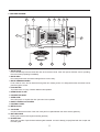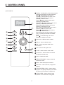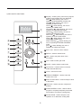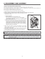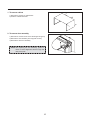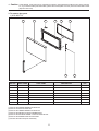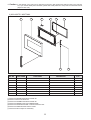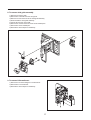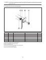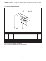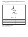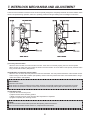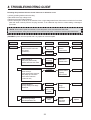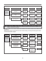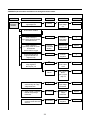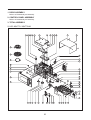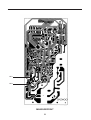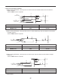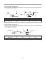
1
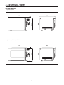
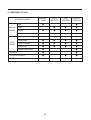
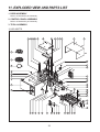
S/M No. :
OC9Q3T7S01
Service Manual
Microwave Oven
Model: KOC-9Q3T7S
KOC-9Q4T7S
KOC-9Q4T7WA9
✔ Caution
: In this Manual, some parts can be changed for improving,
their performance without notice in the parts list. So, if you
need the latest parts information, please refer to PPL(Parts
Price List) in Service Information Center (http://svc.dwe.co.kr).
Mar. 2010
PRECAUTIONS TO BE OBSERVED BEFORE AND
DURING SERVICING TO AVOID POSSIBLE
EXPOSURE TO EXCESSIVE MICROWAVE ENERGY
(a) Do not operate or allow the oven to be operated with the door open.
(b) Make the following safety checks on all ovens to be serviced before activating the magnetron or other
microwave source, and make repairs if necessary: (1) Interlock operation, (2) Proper door closing, (3)
Seal and sealing surfaces (arcing, wear, and other damage), (4) Damage to or loosening of hinges and
latches (5) Evidence of dropping or abuse.
(c) Before turning on power to the microwave oven for any service test or inspection within the microwave
generating compartments, check the magnetron, wave guide or transmission line, and cavity for proper
alignment, integrity, and connections.
(d) Any defective or misadjusted components in the interlock, monitor, door seal and microwave
generation and transmission systems shall be repaired, replaced, or adjusted by procedures described
in this manual before the oven is released to the owner.
TABLE OF CONTENTS
1. SAFETY AND PRECAUTIONS....................................................................................................................................2
2. SPECIFICATIONS ........................................................................................................................................................3
3. EXTERNAL VIEW.........................................................................................................................................................4
3-1. OUTER DIMENSION ..........................................................................................................................................4
3-2. FEATURE DIAGRAM .........................................................................................................................................5
4. INSTALLATION ............................................................................................................................................................6
5. CONTROL PANEL .......................................................................................................................................................7
6. DISASSEMBLY AND ASSEMBLY ..............................................................................................................................8
7. INTERLOCK MECHANISM AND ADJUSTMENT.....................................................................................................19
8. TROUBLE SHOOTING GUIDE ..................................................................................................................................20
9. MESUREMENT AND TEST .......................................................................................................................................25
9-1. MEASUREMENT OF THE MICROWAVE POWER OUTPUT ........................................................................25
9-2. MICROWAVE RADIATION TEST ....................................................................................................................26
9-3. COMPONENT TEST PROCEDURE................................................................................................................27
9-4. COMPONENT ACTION....................................................................................................................................28
10. WIRING DIAGRAM...................................................................................................................................................29
11. EXPLODED VIEW AND PARTS LIST ..................................................................................................................30
11-1. DOOR ASSEMBLY.........................................................................................................................................30
12-2. CONTROL PANEL ASSEMBLY.....................................................................................................................30
13-3. TOTAL ASSEMBLY ........................................................................................................................................30
12. PRINTED CIRCUIT BOARD ....................................................................................................................................31
13. P.C.B CIRCUIT DIAGRAM.......................................................................................................................................38
1
1. SAFETY AND PRECAUTIONS
1. FOR SAFE OPERATION
Damage that allows the microwave energy (that cooks or heats the food) to escape will result in poor cooking and may
cause serious bodily injury to the operator.
IF ANY OF THE FOLLOWING CONDITIONS EXIST, OPERATOR MUST NOT USE THE APPLIANCE. (Only a trained
service personnel should make repairs.)
1) A broken door hinge.
2) A broken door viewing screen.
3) A broken front panel, oven cavity.
4) A loosened door lock.
5) A broken door lock.
The door gasket plate and oven cavity surface should be kept clean.
No grease, soil or spatter should be allowed to build up on these surfaces or inside the oven.
DO NOT ATTEMPT TO OPERATE THIS APPLIANCE WITH THE DOOR OPEN.
The microwave oven has concealed switches to make sure the power is turned off when the door is opened.
Do not attempt to defeat them.
DO NOT ATTEMPT TO SERVICE THIS APPLIANCE UNTIL YOU HAVE READ THIS SERVICE MANUAL.
2. FOR SAFE SERVICE PROCEDURES.
1. If the oven is operative prior to servicing, a microwave emission check should be performed prior to servicing the
oven.
2. If any certified oven unit is found to servicing, a microwave emission check should be performed prior to servicing the
oven.
(a) inform the manufacturer, importer or assembler,
(b) repair the unit at no cost to the owner,
(c) attempt to ascertain the cause of the excessive leakage,
(d) tell the owner of the unit not to use the unit until the oven has been brought into compliance.
3. If the oven operates with the door open, the service person should tell the user not to operate the oven and contact
the manufacturer immediately.
IMPORTANT
The wire in this mains lead coloured in accordance with the following code.
Green-and-yellow : Earth
Blue
: Neutral
Brown
: Live
As the colours of the wires in the mains lead of this appliance may not correspond with the coloured markings
identifying the terminals in your plug, proceed as follows.
The wire which is coloured green-and-yellow must be connected to the terminal in the plug which is marked with the
letter ‘E’ or by earth symbol or green-and-yellow.
The wire which is coloured blue must be connected to the terminal which is marked with the letter ‘N’ or coloured
black.
The wire which is coloured brown must be connected to the terminal which is marked with the letter ‘L’ or coloured
red.
NOTE : This oven is designed for counter-top use only.
2
2. SPECIFICATIONS
MODEL
KOC-9Q3T7S
POWER SUPPLY
230V~50Hz, SINGLE PHASE WITH EARTHING
MICROWAVE
1400W
POWER
GRILL
1250W
CONSUMPTION
CONVECTION
1250W
COMBINATION
2700W
MICROWAVE ENERGY OUTPUT
900W (IEC 705)
MICROWAVE FREQUENCY
2450MHz
OUTSIDE DIMENSIONS (W X D X H)
513X382X311mm(20.2X15X12.2 in.)
CAVITY DIMENSIONS (W X D X H)
354X341X231mm(13.9X13.4X9.1 in.)
NET WEIGHT
Approx. 16.6Kg (46.6 lbs.)
TIMER
60 minutes
FUNCTION SELECTIONS
Microwave / Grill / Convection / Combination
POWER SELECTIONS
10 LEVELS
CAVITY VOLUME
0.99 Cu. Ft
* SPECIFICATION ARE SUBJECT TO CHANGE WITHOUT NOTICE.
MODEL
KOC-9Q4T7S / 9Q4T7WA9
POWER SUPPLY
230V~50Hz, SINGLE PHASE WITH EARTHING
MICROWAVE
1400W
POWER
GRILL
1250W
CONSUMPTION
CONVECTION
1250W
COMBINATION
2700W
MICROWAVE ENERGY OUTPUT
900W (IEC 705)
MICROWAVE FREQUENCY
2450MHz
OUTSIDE DIMENSIONS (W X D X H)
513X383X311mm(20.2X15.1X12.2 in.)
CAVITY DIMENSIONS (W X D X H)
354X341X231mm(13.9X13.4X9.1 in.)
NET WEIGHT
Approx. 16.6Kg (46.6 lbs.)
TIMER
60 minutes
FUNCTION SELECTIONS
Microwave / Grill / Convection / Combination
POWER SELECTIONS
10 LEVELS
CAVITY VOLUME
0.99 Cu. Ft
* SPECIFICATION ARE SUBJECT TO CHANGE WITHOUT NOTICE.
3
3. EXTERNAL VIEW
1. OUTER DIMENSION
1) KOC-9Q3T7S
382
311
513
2) KOC-9Q4T7S / 9Q4T7WA9
383
311
513
4
2. FEATURE DIAGRAM
2
3
4
5
6
7 8
1
9
13
12
11
10
11. DOOR HOOK
Hook automatically locks and holds the door when the door shuts. If the door opens while the oven is operating,
the oven will stop operating immediately.
12. DOOR SEAL
Door seal prevents the microwave leakage from the oven cavity.
13. DOOR VIEWING SCREEN
Food, inside of oven, can be observed through the door viewing screen. It is designed that the microwave cannot
pass through the screen.
14. TOP HEATER
Top heater turns on if any of heater related mode operates.
15. OVEN FRONT PLATE
16. CONVECTION INLET
17. OVEN LAMP
Oven lamp turns on anytime the door opens and oven operates.
18. SAFETY INTERLOCK SYSTEM
19. CONTROL PANEL
10. METAL RACK
11. COUPLER
Coupler located at the center of the oven cavity and it couples between the motor and the glass tray.
12. ROLLER GUIDE
Roller guide must be used anytime with the glass tray.
13. GLASS TRAY
Glass tray is made of special heat resistant glass material. It must be always properly fitted with the coupler and
the roller guide.
5
4. INSTALLATION
1. Steady, flat location
This microwave oven should be set on a steady, flat surface.
This microwave oven is designed for counter top use only.
2. Leave space behind and side
All air vents should be kept a clearance. If all vents are covered during operation, the oven may overheat and, eventually,
cause failure.
3. Away from Radio and TV sets
Poor television reception and radio interference may result if the oven is located close to a TV, Radio, antenna or feeder
and so on.
Position the oven as far from them as possible.
4. Away from heating appliances and water taps
Keep the oven away from hot air, steam or splash when choosing a place to position it, or the insulation might be
adversely affected and breakdowns occur.
5. Power supply
• Check your local power source. This microwave oven requires a current of approximately 12 amperes, 230V, 50Hz.
• Power supply cord is about 1.0 meters long.
• The voltage used must be the same as specified on this oven. Using a higher voltage may result in a fire or other
accident causing oven damage. Using low voltage will cause slow cooking. We are not responsible for damage
resulting from use of this oven with a voltage of ampere fuse other than those specified.
• This appliance is supplied with cable of special type, which, if damaged, must be repaired with cable of same type.
Such a cable can be purchased from DAEWOO and must be installed by a Qualified Person.
6. Examine the oven after unpacking for any damage such as:
A misaligned door, broken door or a dent in cavity.
If any of the above are visible, DO NOT INSTALL, and notify dealer immediately.
7. Do not operate the oven if it is colder than room temperature.
EARTHING INSTRUCTIONS
This appliance must be earthed. In the event of an electrical short circuit, earthing reduces the risk of the electric shock by
providing an escape wire for the electric current. This appliance is equipped with a cord having a earthing wire with a
earthing plug. The plug must be plugged into an outlet that is properly installed and earthed.
WARNING
Improper use of the earthing plug can result in a risk of electric shock. Consult
a qualified electrician or serviceman if the earthing instructions are not completely understood, or if doubt exists as
to whether the appliance is properly earthed, and either:
If it is necessary to use an extension cord, use only a 3-wire extension cord that has a 3-blade earthing plug, and a
3-slot receptacle that will accept the plug on the appliance.
The marked rating of the extension cord should be equal to or greater than the electrical rating of the appliance, or
Do not use an extension cord.
6
5. CONTROL PANEL
1) KOC-9Q3T7S
1
2
4
5
3
6
7
2 Auto cook : Used to cook or reheat.
q
8
9
0
1 Display : Cooking time, power level, program
indicators and present time are displayed.
MW ( ): When blinking, the oven is
operating in MICROWAVE COOK mode.
Grill ( ): When blinking, the oven is
operating in GRILL mode.
Combi ( ): When blinking, the oven is
operating in COMBI mode.
Convection ( ): When blinking, the oven is
operating in CONVECTION mode.
Defrost ( ): When blinking, the oven is
operating in DEFROST mode.
Auto-cook ( ): When blinking, the oven is
operating in AUTO COOK mode.
Warm ( ): When blinking, the oven is
operating in WARM mode.
Steam Cleaning ( ): When blinking, the
oven is operating in STEAM CLEANING
mode.
gram ( ): When blinking, the oven is
operating in weight input mode.
3 Defrost : Used to defrost foods.
4 MW : Used to set power level of the
microwave.
w
e
5 Grill : Used to select grill mode.
6 Combi : Used to select combi mode.
7 Convection : Used to select convection
mode and selected temp.
8 Clock : Used to set clock.
9 STEAM CLEANING : Used to clean the
inside of the oven
0 Warm : Used to keep the food warm.
q Dial knob : Used to set time, weight and
quantity.
w START/SPEEDY COOK : Used to start a
program or a speedy start(each press adds
30 seconds of microwave cooking time).
e STOP/CLEAR : Used to stop the oven
operation or to delete the cooking data.
7
2) KOC-9Q4T7S / 9Q4T7WA9
1
2
4
5
3
6
7
2 Auto cook : Used to cook or reheat.
q
8
9
0
1 Display : Cooking time, power level, program
indicators and present time are displayed.
MW ( ): When blinking, the oven is
operating in MICROWAVE COOK mode.
Grill ( ): When blinking, the oven is
operating in GRILL mode.
Combi ( ): When blinking, the oven is
operating in COMBI mode.
Convection ( ): When blinking, the oven is
operating in CONVECTION mode.
Defrost ( ): When blinking, the oven is
operating in DEFROST mode.
Auto-cook ( ): When blinking, the oven is
operating in AUTO COOK mode.
Warm ( ): When blinking, the oven is
operating in WARM mode.
Steam Cleaning ( ): When blinking, the
oven is operating in STEAM CLEANING
mode.
gram ( ): When blinking, the oven is
operating in weight input mode.
3 Defrost : Used to defrost foods.
4 MW : Used to set power level of the
microwave.
w
e
5 Grill : Used to select grill mode.
6 Combi : Used to select combi mode.
7 Convection : Used to select convection
mode and selected temp.
8 Clock : Used to set clock.
9 STEAM CLEANING : Used to clean the
inside of the oven.
0 Warm or Dish Warm : Used to keep the food
or dish warm.
q Dial knob : Used to set time, weight and
quantity.
w START/SPEEDY COOK : Used to start a
program or a speedy start(each press adds
30 seconds of microwave cooking time).
e STOP/CLEAR : Used to stop the oven
operation or to delete the cooking data.
8
6. DISASSEMBLY AND ASSEMBLY
- Cautions to be observed when trouble shooting.
Unlike many other appliances, the microwave oven is high-voltage, high-current equipment.
It is completely safety during normal operation. However, carelessness in servicing the oven can result in an
electric shock or possible danger from a short circuit.
You are asked to observe the following precautions carefully.
1. Always remove the power plug from the outlet before servicing.
2. Use an insulated screwdriver and ware rubber gloves when servicing the high voltage side.
3. Discharge the high voltage capacitor before touching any oven
components or wiring.
(1) Check the earthed.
Do not operate on a two-wire extension cord.
The microwave oven is designed to be used with earthed.
It is imperative, therefore, to makes sure it is earthed properly
before beginning repair work.
(2) Warning about the electric charge in the high voltage capacitor.
For about 30 seconds after the operation stopped and electric
charge remains in the high voltage capacitor. When replacing or
checking parts, short between oven chassis and the negative
high terminal of the high voltage capacitor, by using a properly
insulated screwdriver to discharge.
4. When the fuse is blown out due to the operation of the monitor
switch; replace primary interlock switch, secondary interlock switch
and interlock monitor switch.
5. After repair or replacement of parts, make sure that the screws are
properly tightened, and all electrical connections are tightened.
6. Do not operate without cabinet.
CAUTION : Service personnel should remove their watches whenever working close to or replacing the magnetron.
WARNING : When servicing the appliance, need a care of touching or replacing high potential parts because of
electrical shock or exposing microwave. These parts are as follows - HV Transformer, Magnetron,
HV Capacitor, HV Diode.
9
1. To remove cabinet
1) Remove five screws on cabinet back.
2) Push the cabinet backward.
2. To remove door assembly
1) Remove two screws which secure the stopper hinge top.
2) Remove the door assembly from top plate of cavity.
3) Reverse the above for assembly.
NOTE: After replacing the door assembly, perform a
check of correct alignment with the hinge and
cavity front plate.
10
✔ Caution : In this Manual, some parts can be changed for improving, their performance without notice in the parts list.
So, if you need the latest parts information, please refer to PPL(Parts Price List) in Service Information Center
(http://svc.dwe.co.kr).
3. To remove door parts.
1) KOC-9Q3T7S
A01
A02
A03
A04
A05
A06
A07
PART NAME
A08
REF. NO
PART CODE
DESCRIPTION
B01
3512607710
HANDLE DOOR
ABS SG-0760D, SG-175 SPRAY
1
B02
3512209640
FRAME DOOR
ABS XR-401
1
B03
3515204120
STOPPER HINGE *T AS
KOR-6L0B1A
1
B04
3516603100
DOOR-PLATE
SECC 0.5T
1
B05
7122401211
SCREW TAPPING
T2S TRS 4X12 MFZN
2
B06
3512302410
GASKET DOOR
LUPOL 2300
1
B07
3515101310
SPRING HOOK
HSW-2
1
B08
3513101900
HOOK
POM
1
(1) Remove the GASKET DOOR from DOOR AS.
(2) Remove screws from DOOR AS.
(3) Remove the HANDLE DOOR from DOOR AS.
(4) Remove the DOOR-PALTE from FRAME DOOR.
(5) Remove the STOPPER HINGE *T AS from DOOR-PLATE.
(6) Remove the SPRING HOOK and the HOOK.
(7) Reverse the above steps for reassembly.
11
Q'TY
✔ Caution : In this Manual, some parts can be changed for improving, their performance without notice in the parts list.
So, if you need the latest parts information, please refer to PPL(Parts Price List) in Service Information Center
(http://svc.dwe.co.kr).
2) KOC-9Q4T7S / 9Q4T7WA9
A01
A02
A03
A04
A05
A06
A07
PART NAME
A08
REF. NO
PART CODE
DESCRIPTION
B01
3512607710
HANDLE DOOR
ABS SG-0760D, SG-175 SPRAY
1
B02
3512209640
FRAME DOOR
ABS XR-401
1
B03
3515204120
STOPPER HINGE *T AS
KOR-6L0B1A
1
B04
3516603100
DOOR-PLATE
SECC 0.5T
1
B05
7122401211
SCREW TAPPING
T2S TRS 4X12 MFZN
2
B06
3512302410
GASKET DOOR
LUPOL 2300
1
B07
3515101310
SPRING HOOK
HSW-2
1
B08
3513101900
HOOK
POM
1
(1) Remove the GASKET DOOR from DOOR AS.
(2) Remove screws from DOOR AS.
(3) Remove the HANDLE DOOR from DOOR AS.
(4) Remove the DOOR-PALTE from FRAME DOOR.
(5) Remove the STOPPER HINGE *T AS from DOOR-PLATE.
(6) Remove the SPRING HOOK and the HOOK.
(7) Reverse the above steps for reassembly.
12
Q'TY
4. Method to reduce the gap between the door seal and the oven front surface.
(1) To reduce gap located on part ‘A’.
• Loosen two screws on stopper hinge top, and then push the door
to contact the door seal to oven front surface.
• Tighten two screws.
A
(2) To reduce gap located on part ‘B’.
• Loosen two screws on stopper hinge under, and then push the
door to contact the door seal to oven front surface.
• Tighten two screws.
B
NOTE : A small gap may be acceptable if the microwave leakage does not exceed 4mW/cm2.
13
✔ Caution : In this Manual, some parts can be changed for improving, their performance without notice in the parts list.
So, if you need the latest parts information, please refer to PPL(Parts Price List) in Service Information Center
(http://svc.dwe.co.kr).
5. To remove control panel parts.
1) KOC-9Q3T7S
B01
B02
B05
B03 B04
B06
PART NAME
DESCRIPTION
B07
REF. NO
PART CODE
B01
3513412110
KNOB DIAL
B02
3516737190
CONROL-PANEL
ABS SG-0760D, SG-175
1
B03
3516912730
BUTTON FUNCTION-A
ABS SG-0760D, SG-175
1
B04
7122401211
SCREW TAPPING
T2S TRS 4X12 MFZN
4
B05
3514332650
PCB MAIN AS
KOC-9Q4T7S
1
B06
7121301011
SCREW TAPPING
T2S PAN 3X10 MFZN
9
B07
7122401211
SCREW TAPPING
T2S TRS 4X12 MFZN
4
ABS SG-0760D, SG-175
(1) Pull out the KNOB DIAL from CONTROL-PANEL AS.
(2) Remove screws securing the PCB MAIN AS.
(3) Pull out the PCB MAIN AS.
(4) Pull out the BUTTON FUNCTION A and B.
(5) Reverse the above steps for reassembly.
14
Q'TY
1
✔ Caution : In this Manual, some parts can be changed for improving, their performance without notice in the parts list.
So, if you need the latest parts information, please refer to PPL(Parts Price List) in Service Information Center
(http://svc.dwe.co.kr).
2) KOC-9Q4T7S / 9Q4T7WA9
B01
B02
B05
B03 B04
B06
PART NAME
DESCRIPTION
B07
REF. NO
PART CODE
B01
3513412110
KNOB DIAL
ABS SG-0760D, SG-175
1
B02
3516737190
CONROL-PANEL
ABS SG-0760D, SG-175
1
B03
3516912730
BUTTON FUNCTION-A
ABS SG-0760D, SG-175
1
B04
7122401211
SCREW TAPPING
T2S TRS 4X12 MFZN
4
BO5
3514332650
PCB MAIN AS
KOC-9Q4T7S
1
KOC-9Q4T7WA9
1
B06
7121301011
SCREW TAPPING
T2S PAN 3X10 MFZN
9
B07
7122401211
SCREW TAPPING
T2S TRS 4X12 MFZN
4
3514334700
(1) Pull out the KNOB DIAL from CONTROL-PANEL AS.
(2) Remove screws securing the PCB MAIN AS.
(3) Pull out the PCB MAIN AS.
(4) Pull out the BUTTON FUNCTION A and B.
(5) Reverse the above steps for reassembly.
15
Q'TY
6. To remove high voltage capacitor.
(1) Remove a screw which secure the grounding ring
terminal of the H.V.diode and the capacitor holder.
(2) Remove the H.V. diode from the capacitor holder.
(3) Reverse the above steps for reassembly.
◆ High voltage circuit wiring
7. To remove magnetron.
(1) Remove a screw which secure the magnetron.
(2) Remove the magnetron.
(3) Reverse the above steps for reassembly.
CAUTION : Never install the magnetron without the metallic gasket plate which is packed with each magnetron to
prevent microwave leakage. Whenever repair work is carried out on magnetron, check the microwave
leakage. It shall not exceed 4mW/cm2 for a fully assembled oven with door normally closed.
Metallic
gasket
plate
Magnetron
antenna
Wave guide Magnetron antenna
Cooling fin
Filament
terminal
<MAGNETRON>
Metallic gasket plate
16
8. To remove wind guide assembly.
1) Remove a screw for earth.
2) Remove the noise filter from the wind guide.
3) Remove a screw which secure the wind guide assembly.
4) Draw forward the wind guide assembly.
5) Pull the fan from the motor shaft.
6) Remove two screws which secure the motor shaded pole.
7) Remove the motor shaded pole.
8) Reverse the above steps for reassembly.
9. To remove H.V.transformer.
1) Remove four screws holding the H.V.transformer.
2) Remove the H.V.transformer.
3) Reverse the above steps for reassembly.
17
✔ Caution : In this Manual, some parts can be changed for improving, their performance without notice in the parts list.
So, if you need the latest parts information, please refer to PPL(Parts Price List) in Service Information Center
(http://svc.dwe.co.kr).
10. To remove fan convection assembly parts.
C04 C05
C06
C01
C02
C03
REF. NO
PART CODE
PART NAME
DESCRIPTION
H08
3511801400
FAN CONVECTION AS
KOC-9Q0T7S
1
C01
3511414400
COVER FAN CONVECTION
SBHG-2 T0.6
1
C02
3963511420
MOTOR SHADED POLE
230V 50HZ MW10CA-T04
1
C03
7S432X4081
SPECIAL SCREW
TT3 TRS 4X8 SE MFZN
2
C04
3511801200
FAN CONVECTION
SBHG T0.5
1
C05
7400104011
WASHER PLAIN
PW-1-4 MFZN
1
C06
7S627W40X1
NUT HEX
NUT FLANGE M4X0.7P MFZN
1
(1) Remove four screws from the inside of cavity.
(2) Remove NUT HEX at the center of the fan.
(3) Remove WASHER PLAIN.
(4) Remove two screws from the COVER FAN CONVECTION.
(5) Pull out the MOTOR SHADED POLE.
(6) Reverse the above steps for assembly.
18
Q'TY
✔ Caution : In this Manual, some parts can be changed for improving, their performance without notice in the parts list.
So, if you need the latest parts information, please refer to PPL(Parts Price List) in Service Information Center
(http://svc.dwe.co.kr).
11. To remove top heater assembly parts.
D02
D06
D05
D03
D04
D01
REF. NO
PART CODE
PART NAME
DESCRIPTION
H44
3512807530
HEATER *T AS
KOC-9Q0T7S
1
D01
3512805800
HEATER MIRACLON
230V 800W 270MM
1
D02
3511414500
COVER HEATER *T
SA1D T0.5
1
D03
3512808200
HEATER REFLECTOR
STS430 T0.4
1
D04
7123400808
SCREW TAPPING
T2S BIN 4X8 STS
2
D05
3510611300
BRACKET COVER HEATER
SBHG T0.5
1
D06
7123400808
SCREW TAPPING
T2S BIN 4X8 STS
1
(1) Remove a screw from the BRACKET COVER HEATER.
(2) Remove the BRACKET COVER HEATER from the COVER HEATER *T.
(3) Remove the HEATER MIRACLON.
(4) Remove two screws from the HEATER REFLECTOR.
(5) Remove the HEATER REFLECTOR from the COVER HEATER *T.
(6) Reverse the above steps for reassembly.
19
Q'TY
✔ Caution : In this Manual, some parts can be changed for improving, their performance without notice in the parts list.
So, if you need the latest parts information, please refer to PPL(Parts Price List) in Service Information Center
(http://svc.dwe.co.kr).
12. To remove guide air assembly parts.
REF. NO
PART CODE
PART NAME
DESCRIPTION
H45
3512525510
GUIDE AIR AS
KOC-9Q0T7S
1
E01
3512528410
GUIDE AIR
SAID T0.5
1
E02
3512806700
HEATER *U
230V 400W TC
1
E03
3513004400
HOLDER HEATER
STS 301 T0.5
1
E04
7123400808
SCREW TAPPING
T2S BIN 4X8 STS
1
(1) Remove a screw from the GUIDE AIR.
(2) Remove the HOLDER HEATER from the GUIDE AIR.
(3) Remove the HEATER *U.
(4) Reverse the above steps for reassembly.
20
Q'TY
7. INTERLOCK MECHANISM AND ADJUSTMENT
The door lock mechanism is a device which has been specially designed to completely eliminate microwave radiation when
the door is opened during operation, and thus to perfectly prevent the danger resulting from the leakage of microwave.
(1) Primary interlock switch
When the door is closed, the hook locks the oven door. If the door is not closed properly, the oven will not operate.
When the door is closed, the hook pushes the button of the microswitch. Then the button of the primary interlock switch
bring it under ON condition. (NO position)
(2) DOM switch and interlock monitor switch
When the door is closed, the hook pushes the lock lever downward. The hook presses the button of the interlock monitor
switch to bring it under OFF condition (NO position) and the lock lever presses the button of the DOM switch to bring it
under ON condition. (NO position)
ADJUSTMENT :
Interlock monitor switch
When the door is closed, the interlock monitor switch should be opened (NO position) before other switches are closed.
When the door is opened, the interlock monitor switch should be closed (NC position) after other switches are opened.
(3) Adjustment steps
a) Loosen the one mounting screw.
b) Adjust interlock switch assembly position.
c) Make sure that lock lever moves smoothly after adjustment is completed.
d) Tighten completely two mounting screws.
NOTE :
Microwave emission test should be performed after adjusting interlock mechanism.
If the microwave emission exceed 4mW/cm 2 , readjust interlock mechanism.
21
8. TROUBLESHOOTING GUIDE
Following the procedure below to check if the oven is defective or not.
1) Check grounding before trouble checking.
2) Be careful of the high voltage circuit.
3) Discharge the high voltage capacitor.
4) When checking the continuity of the switches, fuse or high voltage transformer, disconnect one load wire from these
parts and check continuity with the AC plug removed. To do otherwise may result in a false reading or damage to
your meter.
NOTE : When electric parts are checked, be sure the power cord is not inserted the wall outlet.
Check wire harness, wiring and connection of the terminals and power cord before check the parts listed below.
(TROUBLE 1) Oven does not operate at all : any inputs can not be accepted.
CONDITION
Fuse blows.
CHECK
Check continuity of
interlock monitor switch with
door closed
(COM↔NC)
RESULT
CAUSE
Continuity
Malfunction of
Interlock
monitor switch
(COM↔NC)
REMEDY
Replace
No continuity
No
Continuity
Check continuity of
both primary and secondary
interlock switch with door closed
Malfunction of
interlock switch
Replace
Continuity
Continuity
Check continuity of
primary interlock switch contact with
door partially open until interlock
monitor switch contact close
( COM↔NC close )
Check continuity of
primary winding of low voltage
transformer
0 Ωor infinite
Approx.
530Ω ~ 1130Ω
( normal )
Fuse again
blows
Disconnect high voltage
fuse and operate the unit
22
Shorted contacts
of primary
interlock Switch
Defective low
voltage
transformer
Defective
high voltage
transformer
Replace
Replace
Replace
CONDITION
CHECK
RESULT
CAUSE
REMEDY
Outlet has
proper
voltage
fuse does not
blow?
Check continuity of
magnetron
No
continuity
Defective
magnetron.
Replace
Check continuity of noise filter
board
No
continuity
Defective line
filter board
Replace
Check continuity of
power supply cord
No
continuity
Open power
supply cord
Replace
No
continuity
Defective touch
control circuit
Replace
NOTE : All these switches must be replaced at the same time, please refer to (7.Interlock mechanism and
adjust) for adjustment instructions
(TROUBLE 2)
Display shows all figures selected, but oven does not start cooking, even though desired program and time
are set and start button is tapped.
CONDITION
CHECK
RESULT
CAUSE
REMEDY
Turn table
motor and
oven lamp
do
not turn on
Check continuity of
primary interlock switch
No
continuity
Malfunction of
primary interlock
switch
Adjust or
replace
Check continuity of
secondary interlock
and D.O.M switch
No
continuity
Malfunction of
secondary
Interlock and
D.O.M switch
Adjust or
replace
Check D.C voltage
being supplied to
RELAY(RY2) coil
0V
Defective touch
control Circuit
Replace
Approx.
12V DC
Fault contacts
of RELAY
(RY2) or open
relay coil.
Replace
23
TROUBLE 3) No microwave oscillation even though fan motor rotates.
CONDITION
CHECK
RESULT
CAUSE
REMEDY
No
microwave
oscillation
Check continuity of
high voltage fuse
No
continuity
Defective
high voltage
fuse
Replace
Check continuity of
high voltage capacitor terminals
with wires removed
Continuity
Defective
high voltage
transformer
1
Check continuity of
high voltage rectifier in forward
and backward
direction with DC megger
Continuity
in backward
direction
Defective high
voltage rectifier
Replace
No microwave oscillation
Connect megger leads to
magnetron terminal and
magnetron body
Continuity
Defective
magnetron
2
Check D.C voltage
being supplied to
RELAY (RY1) coil
0V
Defective
touch control
circuit
Replace
Approx.
12V DC
Faulty contacts of
RELAY
(RY1) or open
relay coil
Replace
Defective
high voltage
transformer
Replace
Defective high
voltage
transformer
Replace
Defective
magnetron
Replace
0
1 Check resistance of primary
or
and secondary coil of high
voltage transformer
1 Check continuity of filament
No continuity
terminal of high voltage
transformer
2 Check continuity of
magnetron heater with wires
removed
No continuity
24
(TROUBLE 4)
Grill heater (upper heater) is not heated; food will not become hot.
CONDITION
Main heater
is not heated.
CHECK
RESULT
CAUSE
REMEDY
Check continuity of
primary interlock switch
No
continuity
Malfunction of
primary Interlock
switch
Adjust or
replace
Check continuity of
DOM switch
No
continuity
Malfunction of
DOM switch
Adjust or
replace
Check continuity of
heater
No
continuity
Defective heater
Check D.C voltage
being supplied to
RELAY (RY3) coil
0V
Defective touch
control circuit
Replace
Approx.
12V DC
Faulty contacts of
RELAY
(RY3) or open
relay coil
Replace
Replace
(TROUBLE 5)
1) Convection heater is not heated; food will not become hot.
2) Convection fan motor does no rotate.
CONDITION
CHECK
RESULT
CAUSE
REMEDY
1)Sub heater
is not
heated.
2)Convection
fan and
motor does
not rotate.
Check continuity of
primary interlock switch
No
continuity
Malfunction of
primary Interlock
switch
Adjust or
replace
Check continuity of
DOM switch
No
continuity
Malfunction of
DOM switch
Adjust or
replace
Check continuity of
(heater or motor)
No
continuity
Defective heater
or motor
Replace
Check D.C voltage
being supplied to
RELAY (RY4, RY2) coil
0V
Defective touch
control circuit
Replace
Approx.
12V DC
Faulty contacts of
RELAY
(RY4, RY2) or
open relay coil
Replace
25
(TROUBLE 6)
The following visual conditions indicate a probable defective touch control Circuit or button P.C.B. assembly
1. Incomplete segments.
1) segment missing
2) partial segments missing
3) digit flickering other than normal fluorescent slight flickering
2. A distinct change in the brightness of one or more numbers exists in the
display.
3. One or more digits in the display are not on when they should be.
4. Display does not count down or up with time cooking or clock operation.
5. Oven is programmable and cooks normally but no display shows.
6. Display obviously jumps in time while counting down.
7. Display counts down noticeably too fast while cooking.
8. Display does not show the time of day when clear button is touched.
9. Oven lamp and turn table motor do not stop although cooking is finished.
Check if the RELAY(RY2) contacts close and if they are close, replace touch control circuit.
CONDITION
CHECK
Display does
not show
programming
at all, even if
keyboard is
touched.
Check each button for
continuity of the button
RESULT
CAUSE
REMEDY
Normal
Malfunction of
touch control
circuit of control
box sub-assembly
Replace
control box
sub-assembly
(TROUBLE 7)
When “ERROR 2 ERROR 3” come on display.
CONDITION
CHECK
RESULT
CAUSE
REMEDY
“ERROR 2 &
ERROR 3”
come on
display
Check continuity of thermistor
(resistance of thermistor)
0Ω or infinite
Replace
Replace
No
continuity
Defective
heater
Replace
continuity
Defective touch
control circuit
Replace
Approx
200k~300kΩ
(room
temperature)
Check continuity of heater
(main, sub)
26
9. MEASUREMENT AND TEST
1. MEASUREMENT OF THE MICROWAVE POWER OUTPUT
Microwave output power can be checked by indirectly measuring the temperature rise of a certain amount of water
exposed to the microwave as directed below.
PROCEDURE
1. A cylindrical container of borosilicate glass is used for the test. It has a maximum thickness of 3mm, an external
diameter of approximately 190mm and a height of approximately 90mm.
The mass of the container is determined.
2. At the start of the test, the oven and the empty container are at ambient temperature. Water having an initial
temperature of 10˚C ± 1˚C is used for the test. The water temperature is measured immediately before it is poured
into the container.
3. A quantity of 1000g ± 5g of water is added to the container and its actual mass obtained.
The container is then immediately placed in the centre of the oven shelf, which is in its lowest normal position.
The oven is operated and the time for the water
temperature to attain 20˚C ± 2˚C is measured. The oven
is then switched off and the final water temperature is
measured within 60s.
NOTE 1 - The water stirred is before its temperature is
measured.
NOTE 2 - Stirring and measuring devices are to have a
low heat capacity.
4. The microwave power output is calculated from the
formula
P = 4,187 •
T2 - T1) + 0.55 • mc T2 - T0)/t
where
P is the microwave power output, in watts ;
mw is the mass of the water, in grams ;
mc is the mass of the container, in grams ;
T0 is ambient temperature, in degrees Celsius ;
T1 is the initial temperature of the water, in degree Celsius ;
T2 is the final temperature of the water, in degrees Celsius ;
t
is the heating time, in seconds, excluding the magnetron filament heating-up time.
✻ The microwave power output is stated in watts, rounded off to the nearest 50W
CAUTION
1. Water load should be measured exactly to 1 liter.
2. Input power voltage should be exactly specified voltage (Refer to 2. SPECIFICATIONS).
3. Ambient temperature should be 20 ± 2°C (68 ± 3.6°F)
✻ Heating time for power output: (T2 = T0)
A (second)
70
64
60
56
52
49
47
44
42
40
38
B (W)
600
650
700
750
800
850
900
950
1000
1050
1100
27
2. MICROWAVE RADIATION TEST
WARNING
1. Make sure to check the microwave leakage before and after repair of adjustment.
2. Always start measuring of an unknown field to assure safety for operating personnel from microwave energy.
3. Do not place your hands into any suspected microwave radiation field unless the safe density level is known.
4. Care should be taken not to place the eyes in direct line with the source of microwave energy.
5. Slowly approach the unit under test until the radiometer reads an appreciable microwave leakage from the
unit under the test.
PROCEDURE
1. Prepare Microwave Energy Survey Meter, 600cc glass beaker,
and glass thermometer 100°C (212°F).
2. Pour 275cc ± 15cc of tap water initially at 20 ± 5°C (68 ± 9°F) in
the 600 cc glass beaker with an inside diameter of approx. 95
mm(3.5 in.).
3. Place it at the center of the tray and set it in a cavity.
4. Close the door and operate the oven.
5. Measure the leakage by using Microwave Energy Survey Meter
with dual ranges, set to 2450MHz.
1) Measured radiation leakage must not exceed the value
prescribed below. Leakage for a fully assembled oven with door
normally closed must be less than 4mW/Cm2.
2) When measuring the leakage, always use the 5 cm (2 in.)
space cone with probe. Hold the probe perpendicular to the
cabinet and door. Place the space cone of the probe on the
door, cabinet, door seem, door viewing screen, the exhaust air
vents and the suction air vents.
3) Measuring should be in a counter-clockwise direction at a rate of 1 in./sec. If the leakage of the cabinet door
seem is unknown, move the probe more slowly.
4) When measuring near a corner of the door, keep the probe perpendicular to the areas making sure the probe
end at the base of the cone does not get closer than 2 in. from any metal. If it does not, erroneous reading may
result.
28
3. COMPONENT TEST PROCEDURE
• High voltage is present at the high voltage terminal of the high voltage transformer during any cooking cycle.
• It is neither necessary nor advisable to attempt measurement of the high voltage.
• Before touching any oven components or wiring, always unplug the oven from its power source and discharge the
capacitor.
1. High voltage transformer
1) Remove connections from the transformer terminals and check continuity.
2) Normal readings should be as follows :
Secondary winding ... Approx. 168 Ω±10%
Filament winding ... Approx. 0 Ω
Primary winding ... Approx. 1.97 Ω
2. High voltage capacitor
1) Check continuity of capacitor with meter on the highest OHM scale.
2) A normal capacitor will show continuity for a short time, and then indicate 10MW once the capacitor charged.
3) A shorted capacitor will show continuous continuity.
4) An open capacitor will show constant 10MΩ.
5) Resistance between each terminal and chassis should be infinite.
3. High voltage diode
1) Isolate the diode from the circuit by disconnecting the leads.
2) With the ohmmeter set on the highest resistance scale measure the resistance across the diode terminals.
Reverse the meter leads and again observe the resistance reading. Meter with 6V, 9V or higher voltage batteries
should be used to check the front-back resistance of the diode, otherwise an infinite resistance may be read in
both directions. A normal diode's resistance will be infinite in one direction and several hundred kΩin the other
direction.
4. Magnetron
For complete magnetron diagnosis, refer to "Measurement of the Microwave Output Power." Continuity checks can
only indicate and open filament or a shorted magnetron. To diagnose for an open filament or a shorted magnetron,
1) Isolate magnetron from the circuit by disconnecting the leads.
2) A continuity check across magnetron filament terminals should indicate 0.1 Ωor less.
3) A continuity check between each filament terminal and magnetron case should read open.
5. Fuse
If the fuse in the primary and monitor switch circuit is blown when the door is opened, check the primary and
monitor switch before replacing the blown fuse. In case the fuse is blown by an improper switch operation, replace
the defective switch and fuse at the same time. Replace just the fuse if the switches operate normally.
29
4. COMPONENT ACTION
COOKING MODE
M/W
MANUAL
MODE
MAGNETRON
SUB
HEATER
●
CONVECTION FAN
●
GRILL
COMBI
MAIN
HEATER
●
CONVECTION
●
●
●
●
●
●
●
●
●
ROAST PORK
●
●
●
●
ROAST BEEF
●
●
●
●
ROAST CHICKEN
●
●
●
●
BAKED FISH
●
●
●
●
FRESH VEGETABLES
●
●
DEFROST
●
●
STEAM CLEANING
●
AUTO
MODE
WARM
30
●
●
●
●
10. WIRING DIAGRAM
31
11. EXPLODED VIEW AND PARTS LIST
1. DOOR ASSEMBLY
Refer to 6. Disassembly and assembly.
2. CONTROL PANEL ASSEMBLY
Refer to 6. Disassembly and assembly.
3. TOTAL ASSEMBLY
1) KOC-9Q3T7S
H01
H31
H32
H46
H48
H49
H52
H50
H51
H47
H45
H53
H54
H55
H57
H42
H41
H56
H40
H05
H02
H03
H39
H38
H43
H09
H44
H08
H04
H37
H10
H36
H35
H29
H25
H19
H11
H23
H22
H24
H26
H33
H34
H18
H17
H07
H06
H12
H13
H14
32
H16
H15
H16
H27
H28
H30
H21
H20
✔ Caution : In this Manual, some parts can be changed for improving, their performance without notice in the parts list.
So, if you need the latest parts information, please refer to PPL(Parts Price List) in Service Information Center
(http://svc.dwe.co.kr).
REF. NO
PART CODE
PART NAME
DESCRIPTION
H01
3516119900
CAVITY AS
KOC-9Q0T7S
1
H02
3511403800
COVER WAVE GUIDE
MICA T0.35
1
H03
7113400810
SCREW TAPPING
T1 BIN 4X8 STS430 MFZN
1
H04
3511414800
COVER LAMP
PE 0.1T
1
H05
3517413410
COUPLER
TEFLON
1
H06
3966031800
MOTOR SYNCRO
49TYD -5C
1
H07
7122400611
SCREW TAPPING
T2S TRS 4X6 MFZN
1
H08
3511801400
FAN CONVECTION AS
KOC-9Q0T7S
1
H09
7113400810
SCREW TAPPING
T1 BIN 4X8 STS430 MFZN
4
H10
3514801400
SENSOR TEMPERATURE
PTM-K312-D7
1
H11
7S432X4081
SPECIAL SCREW
TT3 TRS 4X8 SE MFZN
1
H12
3512783520
HARNESS MAIN
KOC-9Q0T7S
1
H13
3513820520
LOCK
PP
1
H14
3513702630
LEVER LOCK
POM
1
H15
4415A17352
SW MICRO
VP-533A-OF SPNO #187 200G
1
H16
4415A66910
SW MICRO
VP-531A-OF/SZM-V16-FA-61
2
H17
3518907020
THERMOSTAT
OFF:120 ON:60 H #187 NB
1
H18
3513003410
HOLDER THERMOSTAT
PP(BK)
1
H19
7122401211
SCREW TAPPING
T2S TRS 4X12 MFZN
2
H20
3510317520
BASE
SBHG T0.5
1
H21
3512101400
FOOT
DASF-310
2
H22
3518303100
CAPACITOR HV
2100VAC 0.98UF #187 +3 -0
1
H23
3513003200
HOLDER HV CAPACITOR
SECC T0.5
1
H24
3518400400
DIODE HV
HVR-1X-3AB 12KV #187
1
H25
7S432X4081
SPECIAL SCREW
TT3 TRS 4X8 SE MFZN
1
H26
3518702100
FUSE HV
5KV 0.7A T.H.V.060T
1
H27
3515201101
STOPPER HINGE *U
SCP-1 T2.5
1
H28
7272400811
SCREW TAPTITE
TT3 TRS 4X8 MFZN
1
H29
3517304300
FOAM
CR 15TX150X15
1
H30
7S312X40A1
SCREW SPECIAL
T1 TRS 4X10 SE MFZN
6
H31
3513601600
LAMP
BL 240V 25W T25 C7A H187
1
H32
4414H50000
FIXTURE AS
KOG-36150S
2
H33
3518124400
TRANS HV
R1S59E ES00
1
H34
3516003700
SPECIAL SCREW
TT3 HEX 4X8 FLG MFZN
4
H35
3516738710
CONTROL-PANEL AS
KOC-9Q3T7S
1
H36
7122401211
SCREW TAPPING
T2S TRS 4X12 MFZN
1
H37
3511728340
DOOR AS
KOC-9Q3T7S
1
H38
7272400811
SCREW TAPTITE
TT3 TRS 4X8 MFZN
2
33
Q'TY
✔ Caution : In this Manual, some parts can be changed for improving, their performance without notice in the parts list.
So, if you need the latest parts information, please refer to PPL(Parts Price List) in Service Information Center
(http://svc.dwe.co.kr).
REF. NO
PART CODE
PART NAME
DESCRIPTION
H39
3512529400
GUIDE WIND AS
KOC-9Q0T7S
1
H40
7122401211
SCREW TAPPING
T2S TRS 4X12 MFZN
1
H41
35113A5QJ5
CORD POWER AS
3X1.5 80X80 120-RTML 1.4M
1
H42
7S312X40A1
SCREW SPECIAL
T1 TRS 4X10 SE MFZN
2
H43
3518003700
MAGNETRON
2M218JFL 6CF
1
H44
3516003700
SPECIAL SCREW
TT3 HEX 4X8 FLG MFZN
3
H45
3512807530
HEATER *T AS
KOC-9Q0T7S
1
H46
3512525510
GUIDE AIR AS
KOC-9Q0T7S
1
H47
7112401011
SCREW TAPPING
T1 TRS 4*10 MFZN
2
H48
7113400810
SCREW TAPPING
T1 BIN 4X8 STS430 MFZN
1
H49
3513304400
INSULATOR HEATER *T
SBHG T0.4
1
H50
3518903800
THERMOSTAT
OFF:160 ON:115 V #187
1
H51
7121400611
SCREW TAPPING
T2S PAN 4X6 MFZN
1
H52
7S312X40A1
SCREW SPECIAL
T1 TRS 4X10 SE MFZN
2
H53
3510810800
CABINET AS
KOC-9Q0T7S
1
H54
7S312X40A1
SCREW SPECIAL
T1 TRS 4X10 SE MFZN
5
H55
3517212000
TRAY RACK AS
KOC-9Q0T7S 35MM
1
H56
3512512930
GUIDE ROLLER AS
KOR-121Q3A XAREC
1
H57
441CD35011
TRAY
GLASS DIA:325 1320G
1
34
Q'TY
1. DOOR ASSEMBLY
Refer to 6. Disassembly and assembly.
2. CONTROL PANEL ASSEMBLY
Refer to 6. Disassembly and assembly.
3. TOTAL ASSEMBLY
2) KOC-9Q4T7S / 9Q4T7WA9
H01
H31
H32
H46
H48
H49
H52
H50
H51
H47
H45
H53
H54
H55
H57
H42
H41
H56
H40
H05
H02
H03
H39
H38
H43
H09
H44
H08
H04
H37
H10
H36
H35
H29
H25
H19
H11
H23
H22
H24
H26
H33
H34
H18
H17
H07
H06
H12
H13
H14
35
H16
H15
H16
H27
H28
H30
H21
H20
✔ Caution : In this Manual, some parts can be changed for improving, their performance without notice in the parts list.
So, if you need the latest parts information, please refer to PPL(Parts Price List) in Service Information Center
(http://svc.dwe.co.kr).
REF. NO
PART CODE
PART NAME
DESCRIPTION
H01
3516119900
CAVITY AS
KOC-9Q0T7S
1
H02
3511403800
COVER WAVE GUIDE
MICA T0.35
1
H03
7113400810
SCREW TAPPING
T1 BIN 4X8 STS430 MFZN
1
H04
3511414800
COVER LAMP
PE 0.1T
1
H05
3517413410
COUPLER
TEFLON
1
H06
3966031800
MOTOR SYNCRO
49TYD -5C
1
H07
7122400611
SCREW TAPPING
T2S TRS 4X6 MFZN
1
H08
3511801400
FAN CONVECTION AS
KOC-9Q0T7S
1
H09
7113400810
SCREW TAPPING
T1 BIN 4X8 STS430 MFZN
4
H10
3514801400
SENSOR TEMPERATURE
PTM-K312-D7
1
H11
7S432X4081
SPECIAL SCREW
TT3 TRS 4X8 SE MFZN
1
H12
3512783520
HARNESS MAIN
KOC-9Q0T7S
1
H13
3513820520
LOCK
PP
1
H14
3513702630
LEVER LOCK
POM
1
H15
4415A17352
SW MICRO
VP-533A-OF SPNO #187 200G
1
H16
4415A66910
SW MICRO
VP-531A-OF/SZM-V16-FA-61
2
H17
3518907020
THERMOSTAT
OFF:120 ON:60 H #187 NB
1
H18
3513003410
HOLDER THERMOSTAT
PP(BK)
1
H19
7122401211
SCREW TAPPING
T2S TRS 4X12 MFZN
2
H20
3510317520
BASE
SBHG T0.5
1
H21
3512101400
FOOT
DASF-310
2
H22
3518303100
CAPACITOR HV
2100VAC 0.98UF #187 +3 -0
1
H23
3513003200
HOLDER HV CAPACITOR
SECC T0.5
1
H24
3518400400
DIODE HV
HVR-1X-3AB 12KV #187
1
H25
7S432X4081
SPECIAL SCREW
TT3 TRS 4X8 SE MFZN
1
H26
3518702100
FUSE HV
5KV 0.7A T.H.V.060T
1
H27
3515201101
STOPPER HINGE *U
SCP-1 T2.5
1
H28
7272400811
SCREW TAPTITE
TT3 TRS 4X8 MFZN
1
H29
3517304300
FOAM
CR 15TX150X15
1
H30
7S312X40A1
SCREW SPECIAL
T1 TRS 4X10 SE MFZN
6
H31
3513601600
LAMP
BL 240V 25W T25 C7A H187
1
H32
4414H50000
FIXTURE AS
KOG-36150S
2
H33
3518124400
TRANS HV
R1S59E ES00
1
H34
3516003700
SPECIAL SCREW
TT3 HEX 4X8 FLG MFZN
4
H35
3516738700
CONTROL-PANEL AS
KOC-9Q4T7S
1
KOC-9Q4T7WA9
1
3516738780
Q'TY
H36
7122401211
SCREW TAPPING
T2S TRS 4X12 MFZN
1
H37
3511728330
DOOR AS
KOC-9Q4T7S
1
H38
7272400811
SCREW TAPTITE
TT3 TRS 4X8 MFZN
2
36
✔ Caution : In this Manual, some parts can be changed for improving, their performance without notice in the parts list.
So, if you need the latest parts information, please refer to PPL(Parts Price List) in Service Information Center
(http://svc.dwe.co.kr).
REF. NO
PART CODE
PART NAME
DESCRIPTION
H39
3512529400
GUIDE WIND AS
KOC-9Q0T7S
1
H40
7122401211
SCREW TAPPING
T2S TRS 4X12 MFZN
1
H41
35113A5QJ5
CORD POWER AS
3X1.5 80X80 120-RTML 1.4M
1
H42
7S312X40A1
SCREW SPECIAL
T1 TRS 4X10 SE MFZN
2
H43
3518003700
MAGNETRON
2M218JFL 6CF
1
H44
3516003700
SPECIAL SCREW
TT3 HEX 4X8 FLG MFZN
3
H45
3512807530
HEATER *T AS
KOC-9Q0T7S
1
H46
3512525510
GUIDE AIR AS
KOC-9Q0T7S
1
H47
7112401011
SCREW TAPPING
T1 TRS 4*10 MFZN
2
H48
7113400810
SCREW TAPPING
T1 BIN 4X8 STS430 MFZN
1
H49
3513304400
INSULATOR HEATER *T
SBHG T0.4
1
H50
3518903800
THERMOSTAT
OFF:160 ON:115 V #187
1
H51
7121400611
SCREW TAPPING
T2S PAN 4X6 MFZN
1
H52
7S312X40A1
SCREW SPECIAL
T1 TRS 4X10 SE MFZN
2
H53
3510810800
CABINET AS
KOC-9Q0T7S
1
H54
7S312X40A1
SCREW SPECIAL
T1 TRS 4X10 SE MFZN
5
H55
3517212000
TRAY RACK AS
KOC-9Q0T7S 35MM
1
H56
3512512930
GUIDE ROLLER AS
KOR-121Q3A XAREC
1
H57
441CD35011
TRAY
GLASS DIA:325 1320G
1
37
Q'TY
12. PRINTED CIRCUIT BOARD
CIRCUIT CHECK PROCEDURE
1. Low voltage transformer check
The low voltage transformer is located on the P.C.B.
Measuring condition: Input voltage: 230V / Frequency: 50Hz
1
9
Terminal
Voltage(load)
Voltage(no load)
8
7
7-8-9
DC 13.5 V
AC 37 V
3
NOTE
1. Secondary side voltage of the low voltage transformer changes in proportion to fluctuation of power source
voltage.
2. The allowable tolerance of the secondary voltage is within ± 5% of nominal voltage.
2. Voltage Check
- Key check point
NO
CHECK POINT
1
IC1 PIN 5, 34, 35
2
IC1 PIN 10
REMARK
5VDC±5%
5V
0V
3
T
T : 20 ms(50Hz)
T
T : 250 ns(4MHz)
IC1 PIN 2 OR 3
5V
0V
- Check method
NO
MEASURE POINT
WAVE FORM
REMEDY
REMARK
1
MP1
DC 5V±5%
Replace VL1,EC1,C4,C5
NO LOAD
2
MP2
DC 12V±20%
Replace D14,D15,EC2,R21,D12
NO LOAD
NOTE: Each measure point must be measured with GND points.
38
MP1
MP2
MEASUREPOINT
39
3. Case of no microwave oscillation
1) When touching M/W button, oven lamp turns on and Fan motor and turntable rotate, and cook indicator in
display comes on.
*Cause: RELAY 1 does not operate.
B
A
RY1
(MAGNETRON)
D8
R31
D10
R32
D11
RY2
(LAMP,TRAY,FAN)
(CONV.FAN)
23 P12
Q11
22 P13
Q13
V2
R21
STATE
POINT A
POINT B
RELAY 1 ON
+5V DC
GND
RELAY 1 OFF
GND
12V DC
2) When touching M/W button, oven lamp does not turn on and turntable motor does not rotate but cook indicator
in display comes on.
*Cause: RELAY 2 does not operate.
B
R31
RY2
(LAMP,TRAY,FAN)
(CONV.FAN)
A
R32
D11
22 P13
Q13
V2
R21
STATE
POINT A
POINT B
RELAY 2 ON
+5V DC
GND
RELAY 2 OFF
GND
12V DC
- Check method
3) When touching M/W button, oven lamp turns on and fan motor does not rotate but cook indicator in display
comes on.
*Cause: RELAY 2 does not operate.
R31
RY2
(LAMP,TRAY,FAN)
(CONV.FAN)
23 P12
Q11
B
A
D10
R32
D11
22 P13
V2
Q13
R21
STATE
POINT A
POINT B
RELAY 2 ON
+5V DC
GND
RELAY 2 OFF
GND
12V DC
- Check method
40
4. Case of no heating of top heater main.
When touching GRILL or COMBI or CONVECTION button, oven lamp turns on and fan motor and turntable rotate,
and cook indicator in display comes on.
*Cause: RELAY 3 does not operate.
A
R16
B
24 P11
RY3
(GRILL)
Q8
D7
Q7
STATE
POINT A
POINT B
RELAY 3 ON
+5V DC
GND
RELAY 3 OFF
GND
12V DC
5. Case of no heating of top heater sub.
When touching GRILL or COMBI or CONVECTION button, oven lamp turns on and Fan motor and turntable rotate
and cook indicator in display comes on.
*Cause: RELAY 4 does not operate.
A
B
R20
RY4
(CONV. HEATER)
25 P10
D9
Q10
Q9
STATE
POINT A
POINT B
RELAY 4 ON
+5V DC
GND
RELAY 4 OFF
GND
12V DC
41
6. Case of no stopping of the count down timer
When the door is opened during operation, the count down timer does not stop.
V1
A
CN1
YW396-02V
D6
1N4148
1
B
Q6 A1266Y
28
V2
2
R9
4.7K
R11
10K
R10
47K
C1
104Z
V1
D.O.M SW
- Check method
POINT
A
B
DOOR OPEN
OPEN
+5V DC
DOOR CLOSED
CLOSE
GND
STATE
CHECK NO
1
METHOD
Check the stage(ON,OFF) of the door open
monitor switch by resistance measurement.
42
REMEDY
Replace door open monitor switch.
P32
13. P.C.B. CIRCUIT DIAGRAM
43
PCB ASS’Y PART LIST
NO
1
2
3
4
5
6
7
8
9
10
11
12
13
14
15
16
17
18
19
20
21
22
23
24
25
26
27
28
29
30
31
32
33
34
35
36
37
38
39
40
41
42
43
44
45
LOCATION
BZ1
CA1
C7
C4,C6
C1~3,C5,C8,C9
EC1
EC2
CN1
CN2
CN3
CN5
D1~D13
D14,D15
IC1
IC2
VL1
DP1
M298
RA1
R1~R8
R12,18,25,26,33
R9,16,20,32
R11,19,R22~24,R27~29
R10,30
R17
R21
R31
R14
R15
CR1
RY1,3
RY2,4
Q1~Q5
Q7,9,11,12,14
Q6
Q8.10,13
LVT1
J4,5,8~10,15,21~24,
J29~31,33,34
J1~3,6,7,11~14,16~20,
J28,J32,35~37
M299
CN101
EN101
SW101~SW111
J101,J102
WF1
PART CODE
3515600100
CN5XB-102M
CCZF1H473Z
CCZB1H102K
CCZF1H104Z
CEXE1H100A
CEXF1E102V
3519150520
4CW215SBD0
30166M5030
3519150540
DZN4148--DZN4004A-13GL86FH47
1K1A7033AP
1CPMC7805C
DDDUA9Q0T3514332420
RA-87X104J
RD-AZ331JRD-AZ102JRD-AZ472JRD-AZ103JRD-AZ473JRD-AZ105JRD-4Z510JRD-4Z101JRN-AZ1002F
RN-AZ1203F
5P4R00MTS5SC0101121
5SC0101487
TZRA106M-TZRC106M-TZTA1266YTZTC3198GR
5EPV035308
85801052GY
NAME
BUZZER
C ARRAY
C CERA
C CERA
C CERA
C ELECTRO
C ELECTRO
CONN WAFER
CONN FILM
CONN WAFER
CONN WAFER
DIODE SWITCHING
DIODE RECTIFIER
IC MICOM
IC RESET
IC REGULATOR
LED DISPLAY
PCB MAIN
R ARRAY
R CARBON FILM
R CARBON FILM
R CARBON FILM
R CARBON FILM
R CARBON FILM
R CARBON FILM
R CARBON FILM
R CARBON FILM
R METAL FILM
R METAL FILM
RESONATOR CERA
SW RELAY
SW RELAY
TR
TR
TR
TR
TRANS POWER
WIRE COPPER
BM-20K
6P(5) 1000PF M 50V
50V HIKF 0.047uF Z
102K 50V AXIAL
50V HIKF 0.1uF Z
50V RSS 10MF
25V RSS 1000uF
YW396-02V
HLEM15S-1
MOLEX 35312-0310
YW396-07AV
1N4148 AUTO 52mm
1N4004A AUTO 52mm
TMP86FH47AUG(TMP86CH47AUG)
KIA7033AP
MC7805C
TOF-4422BMA-B14-G
BOARD(92.8x197)
7P(6) 1/8 100K J
1/6 330 OHM 5%
1/6 1K OHM 5%
1/6 4.7K OHM 5%
1/6 10K OHM 5%
1/6 47K OHM 5%
1/6 1M OHM 5%
1/4 51 OHM 5% SMALL
1/4 100 OHM 5% SMALL
1/6 10K 1%
1/6 120K 1%
CRT4.00MS
G5G-1A 1C 1P DC12V
DY2-DC12
KRA-106M (AUTO)
KRC-106M (AUTO)
KTA-1266Y (AUTO) (1015Y)
KTC-3198GR (AUTO) (1015Y)
DMR-161FS
1/0.52 TIN COATING 7.5mm
85801052GY
WIRE COPPER
1/0.52 TIN COATING 10mm
19
3514332520
4CW215RBD0
5S10302010
5S50101Z93
85801052GY
WSJ-159007
PCB SUB
CONN WAFER
SW ROTARY
SW TACT
WIRE COPPER
WIRE FLAT
BOARD(89x197)
HLEM15R-1
RE012305PVB25FINB1-2-24PCE
KPT-1115AM
1/0.52 TIN COATING 10mm
1.25X15X90XC
1
1
1
11
2
1
44
SPECIFICATION
Q'TY
1
1
1
2
6
1
1
1
1
1
1
13
2
1
1
1
1
1
1
8
5
4
8
2
1
1
1
1
1
1
2
2
5
5
1
3
1
15
DAEWOO ELECTRONICS CORP.
1-2, Jeo-dong 1(il)-ga, Jung-gu, Seoul, Korea
C.P.O. BOX 8003 SEOUL, KOREA
TELEX: DWELEC K28177-8
CABLE: “DAEWOOELEC”
S/M NO. :
PRINTED DATE: Mar. 2010
ABOUT THIS MANUAL
VISION CREATIVE, INC.
서울 종로구 통의동
6 번지 이룸빌딩 4 층
담
당
박진형 과장님
MODEL
KOC-9Q3T7S, KOC-9Q4T7S, 9Q4T7WA9 (S/M)
접
2009.09.25
수
1차
2차
일
정
3차
4차
5차
제
판
규
격
인
한
쇄
MEMO 총 46p
09.09.25-전체신규 46p
09.10.14-11p, 12p, 14p, 15p, 17p, 22p, 26p, 31p, 40p, 42p 수정_
신규 10p
09.10.27-11p, 12p, 14p, 15p 수정_ 신규 4p
09.10.29-11p, 12p 수정_ 신규 2p
10.03.03-표지, 표지뒤 (모델명 추가 KOC-9Q4T7WA9), 3p, 4p, 8p,
12p, 15p, 35p, 36p 수정_ 신규 9p
연락처
VISION 담 당
방 문 수
TEL: 730-0660 FAX: 730-3788