1
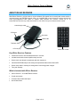
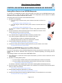
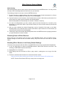
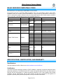
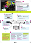
IRLinc Receiver IR to INSTEON® Converter Model : 2411R IRLinc Receiver Owner’s Manual TABLE OF CONTENTS ABOUT IRLINC RECEIVER ......................................................................................................................... 3 Key IRLinc Receiver Features ................................................................................................................... 3 What is Included with IRLinc Receiver ...................................................................................................... 3 WHAT IS INSTEON? .................................................................................................................................... 4 INSTALLATION ............................................................................................................................................ 4 Preparing to Install IRLinc Receiver .......................................................................................................... 4 Installing IRLinc Receiver .......................................................................................................................... 5 USING IRLINC RECEIVER .......................................................................................................................... 5 Using the Credit Card Remote .................................................................................................................. 5 CONTROLLING INSTEON RESPONDERS FROM IRLINC RECEIVER .................................................... 6 Linking IRLinc Receiver to an INSTEON Responder ................................................................................ 6 Unlinking an INSTEON Responder from IRLinc Receiver ........................................................................ 6 CREATING AN INSTEON SCENE ............................................................................................................... 7 ADVANCED FEATURES ............................................................................................................................. 7 Multi-Linking and Multi-Unlinking ............................................................................................................... 7 Restoring Power to IRLinc Receiver ......................................................................................................... 8 Resetting IRLinc Receiver to its Factory Default Settings ......................................................................... 8 X10 PROGRAMMING OPTIONS ................................................................................................................. 9 Setting the X10 Address ............................................................................................................................ 9 Removing the X10 Address ....................................................................................................................... 9 ABOUT INSTEON ...................................................................................................................................... 10 Using Dual-Band INSTEON Devices to Upgrade Your Network ............................................................. 10 Important Note about INSTEON Networks; Split Single-Phase vs. 3-Phase Installation........................ 10 Further Enhancing Reliability .................................................................................................................. 10 ADDITONAL RESOURCES ....................................................................................................................... 10 TROUBLESHOOTING................................................................................................................................ 11 IRLINC RECEIVER COMPATIBLE CODES .............................................................................................. 12 SPECIFICATIONS, CERTIFICATION, AND WARRANTY ........................................................................ 12 Specifications .......................................................................................................................................... 12 Certification .............................................................................................................................................. 12 Limited Warranty ..................................................................................................................................... 13 IRLinc Receiver Owner’s Manual ABOUT IRLINC RECEIVER With IRLinc Receiver, you’ll be able to convert infrared (IR) signals from its credit card remote and/or a universal remote into INSTEON signals. IRLinc is compatible with most universal IR remote controls that come pre-programmed with codes to support many different A/V devices. Control up to 12 scenes/devices from the tiny credit card remote or even more from your universal remote control. Pass-through outlet IR Sensor Set button Status LED Talk-back LED 1/8” mini plug Credit card remote Key IRLinc Receiver Features • Installs and Links to other INSTEON devices in minutes • Included credit card remote simplifies setup and use • Sleek, black case blends in seamlessly with A/V equipment • Indicates INSTEON setup mode activity and operational states with a Status LED • Stores setup state in memory so settings aren’t lost during power outages • Two-year warranty What is Included with IRLinc Receiver • IRLinc Receiver – IR to INSTEON Converter • Credit card remote • IR sensor with double-sided tape • Quick-Start Guide Page 3 of 13 IRLinc Receiver Owner’s Manual WHAT IS INSTEON? Since its inception in 2005, INSTEON has become a best-selling home-control networking technology, offering more reliability and flexibility than any other home management system on the market. INSTEON systems are simple, reliable, and affordable. Simple, because each device takes mere minutes to install. Reliable, because every INSTEON device works as a network repeater, ensuring your commands will not be lost. Affordable, because INSTEON can be integrated into any number of devices easily and at a very low cost. An INSTEON home grows in value with each added INSTEON device, making life more convenient, safe, and fun. How Does INSTEON Work? What makes INSTEON the most reliable home automation network is its dual-mesh network. INSTEON devices use both radio frequency (RF) signals and the home’s existing wiring to talk to each other. In an INSTEON network, every INSTEON device also acts as a repeater, receiving and sending every message to all other devices in the network. So by integrating more INSTEON devices you will strengthen the network and ensure no commands will be lost. No central controller or networking setup is required with an INSTEON network. Simply install your devices and then use a series of button presses or taps to Link your devices together. Throughout this Owner’s Manual, you may see the terms “Controller” or “Responder”. These generic INSTEON terms refer to the components of an INSTEON scene, and are used on a scene-by-scene basis. • Controller – sends INSTEON commands to other devices • Responder – reacts to commands sent out by another INSTEON device An INSTEON device may act as a Controller, Responder, or sometimes both. INSTEON networks are also extremely secure. Each INSTEON device is assigned a unique INSTEON ID, so unless neighbors or would-be hackers have access to your particular device’s INSTEON ID, they won’t be able to control your home, even if they are using similar products. INSTALLATION Preparing to Install IRLinc Receiver CAUTION Read and understand these instructions before installing and retain them for future reference. IRLinc is intended for installation in accordance with the National Electric Code and local regulations in the United States or the Canadian Electrical Code and local regulations in Canada. Use indoors only. IRLinc is not designed nor approved for use on power lines other than 120V 60Hz, single phase. Attempting to use IRLinc on non-approved power lines may have hazardous consequences. Prior to installing IRLinc, please review the entire installation procedure and take the following precautions: • Use indoors or in a properly insulated and weatherproof electrical box only • Don’t plug IRLinc into an outlet controlled by a switch because if the switch is inadvertently turned off, IRLinc won’t have power • Don’t plug IRLinc into a filtered power strip or AC filter • Be sure that the device you want to control is working and that the device’s built-in switch is in the on position • Don’t stack INSTEON home automation devices together by plugging them into each other. Stacked devices may overheat and stop functioning. Also avoid using the pass-through outlets on INSTEON devices for other heatgenerating power supplies. • Don’t use IRLinc to control devices that preserve, maintain, or contribute to human or animal safety or life support If you have any questions, please call: INSTEON Gold Support Line 800-762-7845 Page 4 of 13 IRLinc Receiver Owner’s Manual Installing IRLinc Receiver 1) Mount the IR sensor where it will be in the line of sight of the IR remote you plan to use. Be sure to mount the sensor within 6 feet of an outlet, unless you plan to use an extension cord to power IRLinc. 2) Plug IRLinc into an unswitched wall outlet The IRLinc Status LED will turn on solid 3) Plug the IR sensor’s mini-plug into the jack on the bottom of IRLinc 4) If you are using a universal remote, proceed to step 5. If you are using the included credit card remote, remove its battery isolation tab and proceed to Linking IRLinc Receiver to an INSTEON Responder. 5) 6) Program the universal remote: a) Choose a mode on the remote that you don’t use (e.g., CD, AUX, PVR, etc) b) Use the remote’s documentation to set this mode to one of the NEC three or fourdigit codes c) Point the remote at IRLinc from at least 6 inches away and tap the Power button • If the green Talk-back LED flashes, the IR code is compatible. Continue to Linking. See Linking IRLinc Receiver to an INSTEON Responder. • If the Talk-back LED does not flash, the IR code from the remote is not compatible. Start over from step a with another IR code. OPTIONAL: You can use the pass-through outlet on the front of IRLinc as you would an ordinary uncontrolled wall outlet. However, do not plug another home automation product into this outlet. USING IRLINC RECEIVER Using the Credit Card Remote The included credit card remote is compatible with IRLinc Receiver v1.3+. It is not compatible with X10 devices. Scene Control Buttons These buttons are pre-paired with each other, such that when you Link an INSTEON device to the Up arrow, the Down arrow will also control that device. • Tap the Up arrow to activate the scene • Tap the Down arrow to deactivate the scene • Press & hold the Up arrow to brighten the scene • Press & hold the Down arrow to dim the scene Scene Activation Buttons These buttons provide smooth and simple scene transitions for when a scene doesn’t need an OFF command • Tap to activate a scene • Press & hold to toggle between brightening or dimming the scene All On/Off Buttons These buttons automatically control all devices Linked to any scene in IRLinc for quick, wholehome control • Tap the On button to turn on all devices Linked to IRLinc • Tap the Off button to turn off all devices Linked to IRLinc Add/Remove Buttons These buttons save time by putting IRLinc into Linking / Unlinking Mode without the need to press & hold the Set button on the unit itself • Press & hold the To Scene button for 3 seconds to put IRLinc into Linking Mode • Press & hold the From Scene button for 3 seconds to put IRLinc into Unlinking Mode Page 5 of 13 IRLinc Receiver Owner’s Manual CONTROLLING INSTEON RESPONDERS FROM IRLINC RECEIVER Linking IRLinc Receiver to an INSTEON Responder To use IRLinc as an INSTEON Controller, follow these steps to Link IRLinc and an INSTEON Responder (the device you wish to control with IRLinc) together. Refer to the Responder’s Owner’s Manual for detailed instructions on how to properly install and Link it to IRLinc. The following will work for the most common INSTEON devices: 1) Set IRLinc to Linking Mode: • If you are using a universal remote, press & hold the Set button on IRLinc for 3 seconds The blue IRLinc Status LED will flash once • 2) 3) 4) 5) If you are using the credit card remote, press & hold its To Scene button for 3 seconds The blue IRLinc Status LED will flash once You will have 4 minutes to complete steps 2–4 before Linking Mode automatically times out. Point the universal or credit card remote at IRLinc from a distance of 6 inches or more and then tap the button you want to be learned The blue IRLinc Status LED will begin blinking If you wish the button to toggle ON and OFF commands, proceed to step 4. If you wish to program a discrete ON or OFF command to the button: • Tap the Set button on IRLinc for a discrete ON command • Double-tap the Set button on IRLinc for a discrete OFF command Press & hold the Responder’s Set button for 3 seconds The blue IRLinc Status LED will stop blinking and turn on solid Confirm that Linking was successful by tapping the button you just Linked to on the remote The Responder will respond appropriately Unlinking an INSTEON Responder from IRLinc Receiver If you are no longer going to use an INSTEON Responder that has previously been Linked to IRLinc, it is very important that you Unlink it. Otherwise, IRLinc will retry any commands repetitively, thus slowing down the system. The following will work on the most common INSTEON devices: If the Responder is a multi-scene device, tap the Scene button you wish to remove control from until its LED illuminates 2) Set IRLinc to Unlinking Mode by either: • If you are using a universal remote, press & hold the Set button on IRLinc for 3 seconds • If you are using the credit card remote, press & hold its From Scene button for 3 seconds The blue IRLinc Status LED will flash once You will have 4 minutes to complete steps 2 and 3 before Unlinking Mode automatically times out. 3) Point the universal or credit card remote at IRLinc from a distance of more than 6 inches and then tap the button you want to be unlearned The blue IRLinc Status LED will begin blinking 4) Press & hold the Responder’s Set button for 3 seconds The blue IRLinc Status LED will stop blinking and turn on solid 5) Confirm that Unlinking was successfully by tapping the button you just Unlinked from on the remote The Responder will no longer respond 1) Page 6 of 13 IRLinc Receiver Owner’s Manual CREATING AN INSTEON SCENE INSTEON scenes let you activate dramatic lighting moods with the press of just one button. For example, you can set all the lights in a scene to dim to 50% or turn certain lights on while turning others off, all with the tap of a button on a Controller. INSTEON scenes are very easy to set up – just Link more than one Responder to the same On/Off or Scene button on a Controller. Then, when you press any of the Linked buttons on the Controller, all of the INSTEON devices Linked in the scene will respond as a group. To set up an INSTEON scene, you can individually Link each device to a Controller. Or, save time and create multiple Links. See Multi-Linking and Multi-Unlinking. ADVANCED FEATURES Multi-Linking and Multi-Unlinking Multi-Linking Multi-Linking Mode allows you to Link multiple Responders to a single Controller and quickly create an INSTEON scene. Once the Controller is in Multi-Linking Mode, you can Link any number of Responders, one right after the other. The following will work for the most common INSTEON devices: 1) Set each of the Responders to the state you wish to activate from the Controller • Turn the Responder on or off, set the brightness/On-Level and Ramp Rate, etc. • If the Responder is a multi-scene device (e.g., KeypadLinc), tap the desired Scene button until its LED is in the desired state (on or off) 2) Set the Controller to Linking Mode. (For most Controllers, press & hold the desired On or Scene button for 10 seconds or the Set button for 3 seconds.) 3) Tap the Set button on the Controller. If the Controller does not have a Set button, tap the same On or Scene button you used to put the Controller into Linking Mode. Multi-Linking Mode will automatically time out after 4 minutes of inactivity. 4) One at a time, press & hold each of the Responder’s Set buttons for 3 seconds 5) After you have Linked all the desired Responders, tap the Controller’s Set button to exit Multi-Linking Mode. If the Controller does not have a Set button, tap the same On or Scene button you used to put the Controller into Linking Mode. 6) Test that the INSTEON scene is working properly by tapping the button you just Linked to on the Controller Page 7 of 13 IRLinc Receiver Owner’s Manual Multi-Unlinking Multi-Unlinking Mode can be used to quickly remove devices from an INSTEON scene. You may remove as many of the Linked Responders from the scene as you would like. The following will work for the most common INSTEON devices: 1) Set the Controller to Unlinking Mode. (For most Controllers, press & hold the desired On or Scene button for 10 seconds twice or the Set button for 3 seconds twice.) 2) Tap the Set button on the Controller. If the Controller does not have a Set button, tap the same On or Scene button you used to put the Controller into Unlinking Mode. Multi-Unlinking Mode will automatically time out after 4 minutes of inactivity. 3) For each of the Responders you wish to Unlink, press & hold the Set button for 3 seconds. (If the Responder is a multi-scene device, tap the Scene button you wish to Unlink and then press & hold the Set button.) 4) After you have Unlinked the desired Responders, tap the Controller’s Set button to exit MultiUnlinking Mode. If the Controller does not have a Set button, tap the same On or Scene button you used to put the Controller into Unlinking Mode. 5) Test that you have removed the desired Responders from the INSTEON scene by tapping the button you just Unlinked from on the Controller Restoring Power to IRLinc Receiver IRLinc stores all of its settings, such as Links to other INSTEON devices, with non-volatile memory. Because settings are saved in this non-volatile memory, they will not be lost in the event of a power failure. Resetting IRLinc Receiver to its Factory Default Settings The factory reset procedure will clear IRLinc of all INSTEON Links and any programmed X10 addresses. 1) If you are using IRLinc to control any INSTEON devices, Unlink those devices from IRLinc. See Unlinking an INSTEON Responder from IRLinc. 2) Unplug IRLinc for 10 seconds 3) While holding down the Set button on IRLinc, plug it back in, making sure not to let go of the Set button 4) Continue to hold down the Set button for 3 seconds and then release About 20 seconds after releasing the Set button, the blue IRLinc Status LED will flash twice NOTE: The blue IRLinc Status LED may or may not be on during reset. Page 8 of 13 IRLinc Receiver Owner’s Manual X10 PROGRAMMING OPTIONS IRLinc is X10 ready, meaning that it can send X10 commands to X10 devices. However, to operate in X10 mode, you must first set an X10 Primary Address. As it ships from the factory or after a factory reset procedure, IRLinc will not have an X10 Primary Address set up. NOTE: The included IRLinc credit card remote does not support X10. Setting the X10 Address You must complete the following before IRLinc will send out X10 commands. You can use any of the 256 possible X10 addresses for the X10 Primary Address. 1) Set IRLinc to Linking Mode by pressing & holding the Set button for 3 seconds The blue IRLinc Status LED will flash once 2) Using an X10 controller, send the X10 Primary Address you want to use three times The blue IRLinc Status LED will begin blinking 3) Holding the IR-compatible remote 6 to 12 inches from IRLinc, tap the button you wish to learn The blue IRLinc Status LED will stop blinking and turn on solid NOTE: IRLinc will only send either INSTEON or X10 commands for a given programmed IR code. Also, if switching between INSTEON and X10 mode for a particular IR code, the above steps will need to be performed twice in order to program an X10 command again. Removing the X10 Address If you are no longer going to use IRLinc with an X10 address, it is very important that you Unlink it. Otherwise, IRLinc will continue to send X10 commands and may cause your IR devices to turn on by themselves. 1) Set IRLinc to Linking Mode by pressing & holding the Set button on IRLinc for 3 seconds The blue IRLinc Status LED will flash once 2) Set IRLinc to Unlinking Mode by pressing & holding the Set button on IRLinc for 3 seconds again The blue IRLinc Status LED will flash once 3) Using an X10 controller, send the X10 address you want to remove three times The blue IRLinc Status LED will begin blinking 4) Holding the IR-compatible remote 6 to 12 inches from IRLinc, tap the button you wish to unlearn The blue IRLinc Status LED will stop blinking and turn on solid Page 9 of 13 IRLinc Receiver Owner’s Manual ABOUT INSTEON Using Dual-Band INSTEON Devices to Upgrade Your Network What are phases? The majority of single-family homes in North America have two phases (or “legs”) of 110 Volts coming into their electricity panels. From the panel, they are distributed throughout the home, providing power to outlets and wall switches. These phases come together in some parts of the home to provide 220 Volts of power to large appliances, such as an electric oven or pool pump. Why do I need to bridge these phases? Single-band power line devices send commands via the home’s electricity, but only on a single phase. If the command is intended for a device on the opposite phase, there is a good chance the command will go unnoticed. Installing dual-band INSTEON devices, such as Access Points (#2443), on each phase will allow for devices to communicate between the two phases via RF. Dual-band INSTEON devices embody the full potential of a true INSTEON mesh network. Taking the power line band signal and working in conjunction with the RF band signal, its dual-band function plays out in two ways: • Phase bridger – a receiver of commands, reacting to and translating signals sent from one power phase to the opposite via RF • Signal repeater – a participant in an INSTEON network, repeating commands intended for other devices whether those commands are generated from RF or power line-only devices. To ensure reliability, every INSTEON device confirms that it has received a command. If a Controller does not receive this confirmation, it will automatically retransmit the command up to five times. While using at least one dual-band device is required when using an RF-only device, at least two dual-band devices are recommended to ensure reliable communication across two-phase home wiring systems. For larger applications, it is recommended to install at least one dual-band device for every 750 – 1,000 square feet. Search for dual-band INSTEON devices at: www.smarthome.com/dualband Important Note about INSTEON Networks; Split Single-Phase vs. 3-Phase Installation For the best INSTEON network performance, be sure you have properly installed at least two dual-band INSTEON devices. INSTEON has only been officially tested in a split single-phase residential environment but has been known to work in many 3-phase systems, where three dual-band devices are used (one on each phase). However, due to the potential complexity of its troubleshooting, the INSTEON Gold Support Line is unable to support INSTEON in 3-phase environments. Further Enhancing Reliability As signals travel via the power line or RF throughout the home, they naturally become weaker the farther they travel. The best way to overcome weakened signals is to increase the coverage of the mesh network by introducing more INSTEON devices. It is possible that some audio-video devices, computers, power strips, or other electrical equipment may attenuate INSTEON signals on the power line. You can temporarily unplug suspected devices to test whether the INSTEON signal improves. If it does, then you can plug in filters that will permanently fix the problem. ADDITONAL RESOURCES Find home automation solutions, helpful tips, interactive demos, videos, user forums, and more at the Smarthome Learning Center: www.smarthome.com/learningcenter.html Page 10 of 13 IRLinc Receiver Owner’s Manual TROUBLESHOOTING Problem Possible Cause The Status LED on IRLinc may not be getting IRLinc is not turning on. power. Make sure IRLinc is not plugged into a switched outlet that is turned off. The Responder might have been reset without Unlinking IRLinc from it. Re-Link IRLinc to the Responder. See Linking IRLinc Receiver to an INSTEON Responder. The Responder and IRLinc may be on opposite power line phases. Make sure two dual-band INSTEON devices are properly installed to bridge the two power line phases. The INSTEON signal may be too weak. Add additional INSTEON devices or move around existing INSTEON devices. All INSTEON devices act as INSTEON network repeaters. IRLinc won’t Link or work with a Responder. Large appliances, such as refrigerators or air conditioners, may be producing electrical noise on the power line. Other electrical devices, such as computers, televisions, or power strips, may be absorbing the INSTEON signal. The green Talk-back LED on IRLinc doesn’t flash with remote presses. Solution Install a power line noise filter (#1626-10) to filter electrical noise and minimize signal attenuation. Make sure the IR sensor is firmly plugged into the bottom mini-jack. You may be experiencing interference from a light IRLinc may not be receiving source or TV. Turn off the lights and TV and then IR signals. check to see if IRLinc is responding. Re-position the sensor and try sending the command from the remote again. Responders are taking a long time to respond to IRLinc. IRLinc may be sending commands to a Responder that is no longer in use. Commands for the unused Responder are being resent and loading down the signal. IRLinc can turn off a Responder but nothing happens when I send an ON command from IRLinc. The Responder may be Linked at its off state. A surge or excessive noise on the power line may have glitched it. Unlink any unused Responders from IRLinc. HINT: If you are using home automation software, you can easily check scene membership and eliminate unnecessary Links. If the above doesn’t work, perform a factory reset. See Resetting IRLinc Receiver to its Factory Default Settings. Re-Link the Responder to IRLinc, while the Responder’s load is in the on. See the Responder’s Owner’s Manual for more detailed Linking instructions. Unplug IRLinc for 10 seconds and reinstall. If the above doesn’t work, perform a factory reset. See Resetting IRLinc Receiver to its Factory Default Settings. If you have tried these solutions, reviewed this Owner’s Manual, and still cannot resolve an issue you are having with IRLinc, please call: IRLinc is locked up. INSTEON Gold Support Line 800-762-7845 Page 11 of 13 IRLinc Receiver Owner’s Manual IRLINC RECEIVER COMPATIBLE CODES IRLinc Receiver is an infrared (IR) to INSTEON converter module. Input infrared must be a recognized NEC-compatible code to be recognized by IRLinc. Since NECcompatible codes are utilized by many manufacturers, a large number of manufacturer codes can be used, for many device types. However, since not all products with the NEC brand actually use NEC’s codes, it may take a few attempts to find a code compatible with IRLinc. Remote MFR Part# Mode Manufacturer Code Dish Network 5.3 IR TV NEC 731 880 Harmony VCR NEC VH-604 890 Goldstar 178 TV Kameleon URC-9964B00 NEC 30 VCR NEC 104 Motorola DCP501 Video 1 Motorola 19 or 38 ONE For ALL URC-6131B00 VCR NEC 38 or 104 Pronto Philips TV NEC Code Sets 1, 3 and 6 TSU2000/2001 AV Bose 1131 TV Dell 314 TV GE 1 Philips TIVO Remote IECR06 AV Kenwood 1012 TB Kenwood 230 or 231 TV NEC 1 TV NEC 13, 22, 25, 106, 123, or 125 Radioshack 15-2104 VCR NEC 106 Samsung BN59-00511A DVD Audiovox 75 MX-MX-700 MX-MX-850 URC VCR/TV N/A 289 MX-MX-950 MX-3000 X10 5 in 1 UR74A TV Audiovox 174 UR24A TV Audiovox 22 X10 8 in 1 UR24A TV NEC 17 or 89 UR24A VCR NEC 22 SPECIFICATIONS, CERTIFICATION, AND WARRANTY Specifications View specifications for IRLinc Receiver at: www.smarthome.com/2411R.html Certification This product has been thoroughly tested by ITS ETL SEMKO, a nationally recognized independent thirdparty testing laboratory. The North American ETL Listed mark signifies that the device has been tested to and has met the requirements of a widely recognized consensus of U.S. and Canadian device safety standards, that the manufacturing site has been audited, and that the manufacturer has agreed to a program of quarterly factory follow-up inspections to verify continued conformance. Page 12 of 13 IRLinc Receiver Owner’s Manual Limited Warranty Seller warrants to the original consumer purchaser of this product that, for a period of two years from the date of purchase, this product will be free from defects in material and workmanship and will perform in substantial conformity to the description of the product in this Owner’s Manual. This warranty shall not apply to defects or errors caused by misuse or neglect. If the product is found to be defective in material or workmanship, or if the product does not perform as warranted above during the warranty period, Seller will either repair it, replace it, or refund the purchase price, at its option, upon receipt of the product at the address below, postage prepaid, with proof of the date of purchase and an explanation of the defect or error. The repair, replacement, or refund that is provided for above shall be the full extent of Seller’s liability with respect to this product. For repair or replacement during the warranty period, call the INSTEON Gold Support Line at 800-762-7845 with the Model # and Revision # of the device to receive an RMA# and send the product, along with all other required materials to: Smarthome, Inc. ATTN: Receiving Dept. 16542 Millikan Ave. Irvine, CA 92606-5027 Limitations The above warranty is in lieu of and Seller disclaims all other warranties, whether oral or written, express or implied, including any warranty or merchantability or fitness for a particular purpose. Any implied warranty, including any warranty of merchantability or fitness for a particular purpose, which may not be disclaimed or supplanted as provided above shall be limited to the two-year of the express warranty above. No other representation or claim of any nature by any person shall be binding upon Seller or modify the terms of the above warranty and disclaimer. Home automation devices have the risk of failure to operate, incorrect operation, or electrical or mechanical tampering. For optimal use, manually verify the device state. Any home automation device should be viewed as a convenience, but not as a sole method for controlling your home. In no event shall Seller be liable for special, incidental, consequential, or other damages resulting from possession or use of this device, including without limitation damage to property and, to the extent permitted by law, personal injury, even if Seller knew or should have known of the possibility of such damages. Some states do not allow limitations on how long an implied warranty lasts and/or the exclusion or limitation of damages, in which case the above limitations and/or exclusions may not apply to you. You may also have other legal rights that may vary from state to state. INSTEON Technology Patent U.S Patent No. 7,345,998, International patents pending © Copyright 2011 Smarthome, 16542 Millikan Ave., Irvine, CA 92606, 866-883-9220, www.smarthome.com Rev 04-05-2011 Page 13 of 13