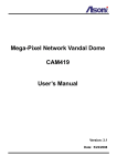
1
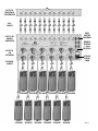
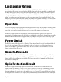
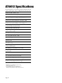
Table of Contents
Functional Description .............................. Page 3
Unpacking ............................................... Page 3
Precautions .............................................. Page 4
Safety Instructions .................................... Page 5
Notes On “Hum” ........................................ Page 6
Cooling .................................................... Page 7
Placement ................................................ Page 7
Rack Mounting ......................................... Page 7
Electrical Connections ............................... Page 8
Input Connections ..................................... Page 8
Zone Volume Controls ................................ Page 8
Output Connections .................................. Page 8
Loudspeaker Phasing ................................ Page 8
Hook-Up Diagram ..................................... Page 9
Loudspeaker Ratings ................................ Page 10
Operation ............................................... Page 10
Power Switch .......................................... Page 10
Remote-Power-On ................................... Page 10
Optic Protection Circuit ............................ Page 10
Circuitry ................................................. Page 11
AC Line Connector And Power Cord ........... Page 11
AC Fuse .................................................. Page 11
Detachable Modular Component (DMC4) ... Page 11
AT6012 Specifications .............................. Page 12
General Maintenance And Service ............. Page 13
Warranty ................................................ Page 14
Obligation To Make Changes .................... Page 14
Save For Your Reference ........................... Page 15
Page 2
Functional Description
The AT6012 is a 12-channel, 6-zone power amplifier designed to provide audiophile-quality sound in multi-room
installations. The AT6012 consists of six 2-channel modules (DMC 4). Each zone’s volume (gain) can be remotely
adjusted via a “dry” 3-wire connection from control devices such as Crestron, Xantech, Phast etc. Please consult the
instruction manuals from those companies to ensure compatibility. The AT6012 can be activated remotely via a DC
current of 3 to 24 V. An Optic Protection Circuit will protect each amplifier module from overloads and shorts and will
automatically reset itself.
Unpacking
The AT6012 has been carefully inspected, tested and packed before leaving the factory. Immediately upon receiving
your amplifier, inspect the carton for evidence of mishandling during shipment. Then, carefully unpack the amplifier
and inspect it for damage. We suggest that you open the carton from the bottom, then carefully turn the box over and
lift the carton away from the amplifier, thus facilitating access to the unit.
Please save the shipping carton and all inner packing materials in the event that the amplifier needs to be shipped for
service or moved to a new location. Should you discover that the amplifier has been damaged during shipping, please
contact your dealer or ATI immediately and request the name of the carrier so a written claim can be made.
THE RIGHT TO A CLAIM AGAINST A PUBLIC CARRIER CAN BE FORFEITED IF THE CARRIER IS NOT NOTIFIED
PROMPTLY IN WRITING AND IF THE SHIPPING CARTON AND PACKING MATERIALS ARE NOT AVAILABLE
FOR INSPECTION BY THE CARRIER. SAVE ALL PACKING MATERIALS UNTIL THE CLAIM HAS BEEN SETTLED.
Page 3
Precautions
The amplifier is a wideband design with substantial power output capability. Certain precautions must be taken to
ensure proper operation.
1. Never expose the unit to moisture.
2. Never plug an input cable into the amplifier while the amplifier is turned on.
3. Never apply the “thumb test” (touching the “hot” lead of the input cable with your finger) to the tip of the input
cable or input jack of the amplifier. RF rectification and/or hum will be created and almost surely will damage the
loudspeakers. ATI will not be responsible for damage to the loudspeakers due to improper use of the equipment.
4. Under no circumstances should the output terminals of the amplifier be short-circuited.
5. Avoid restricting the airflow around the unit. Good airflow is necessary to help ensure proper operation.
6. Be sure that the loudspeakers connected can handle the output power of the amplifier at the loudspeakers’ rated
impedance. The warranty on the amplifier does not cover damage to loudspeakers that have inadequate power
handling capabilities.
7. Do not stack other system components or any other materials directly on top of the unit. The heat-dissipating
system of the amplifier depends on free flowing air around the chassis.
WARNING: DO NOT OPEN AMPLIFIER, RISK OF ELECTRICAL SHOCK! DO NOT ATTEMPT SERVICING
THIS UNIT YOURSELF. REFER SERVICING TO QUALIFIED SERVICE PERSONNEL.
Page 4
Safety Instructions
WARNING: TO REDUCE THE RISK OF FIRE OR ELECTRIC SHOCK, DO NOT EXPOSE THIS UNIT TO RAIN
OR MOISTURE.
Read all the safety and operating instructions before connecting or using this unit.
All warnings on the unit and in this operating manual should be adhered to.
All operating and use instructions should be followed.
Do not use this unit near water: for example, near a bathtub, washbowl, kitchen sink, laundry tub, in a wet basement,
or near a swimming pool.
This unit should be installed so that its location or position does not interfere with its proper ventilation. For example,
it should not be situated on a bed, sofa, rug, or similar surface that may block the ventilation openings: or placed in a
built-in installation, such as bookcase or cabinet, that may impede the flow of air through its ventilation openings.
The unit should be situated away from heat sources such as radiators, heat registers, stoves, or other devices
(including amplifiers) that produce heat.
The unit should be connected to a power-supply outlet only of the voltage and frequency marked on its rear panel.
The power-supply cord should be routed so that it is not likely to be walked on or pinched, especially near the plug,
convenience receptacles, or where the cord exits from the unit.
Clean unit only as recommended in this instruction manual.
The power-supply cord of the unit should be unplugged from the wall outlet when it is to be unused for a long period of time.
Care should be taken so that objects do not fall, and liquids are not spilled, into the enclosure through any openings.
The unit should be serviced by qualified service personnel when:
A. The power cord or the plug has been damaged; or
B. Objects have fallen, or liquid has been spilled, into the unit; or
C. The unit has been exposed to rain, or liquids of any kind; or
D. The unit does not appear to operate normally, or exhibits a marked change in performance; or
E. The device has been dropped, or the enclosure damaged.
To prevent electric shock, do not use the polarized plug with an extension cord, receptacle or other outlet unless the blades
can be fully inserted to prevent blade exposure.
Page 5
Notes On “Hum”
With the growing sophistication of home theater systems, the potential for ground loops is enormous. Do not
automatically assume that one or more of your components are at fault, or even defective. Lately, one of the biggest
culprits is the Cable-TV incoming signal line.
Almost 100% of the cases where hum has been a problem have been due to one or more of the below conditions.
The following notes will help you to determine its cause:
Note 1:
Cable TV systems can sometimes contribute to ground loop problems which cause hum. To determine if your cable
system is the contributing factor, disconnect the Cable TV incoming signal line (round 75 Ohm) at the wall, or the
first component the cable is connected to (i.e. the cable box, or VCR). If the hum is no longer present, you must insert
a 75 Ohm Ground Loop Isolator before reconnecting the line. You should check with your ATI dealer to obtain one.
If the 75 Ohm Ground Loop Isolator works only partially, or not at all, then please read Note 2, Note 3 and Note 4.
Note 2:
Turn the system off and disconnect all inputs from the amplifier. If the hum persists, consult with your dealer or ATI directly.
If the hum disappears, try another set of input cables. Connect one cable at a time to see if one specific cable is responsible.
If any or all cables cause the hum to appear, then your preamp or processor should be evaluated for proper operation.
Note 3:
When there is an audible “hum” through your loudspeakers, even with the volume control low or off, you have a
common problem known as a “ground loop”. A “ground loop” is basically a difference in ground voltages between two
or more components which are connected electrically and which creates multiple current paths where there should
be only one. This difference in potential causes a low-level noise we call “hum”. AC ground-prong loop produces a fairly
loud hum. When installing a system that uses three-wire AC cords with grounding-type plugs, note the units that have
them. An installation that has two or more components that use a 3-prong plug may result in a ground-loop situation.
If it is impractical to rewire your house with an isolated star ground configuration, you may want to try a power
isolation transformer.
WARNING: DO NOT, UNDER ANY CIRCUMSTANCES LIFT THE GROUND (eliminate the round, 3rd prong)
FROM THE PLUG USED WITH THE AT6012–SEVERE SHOCK MAY RESULT!
Note 4:
Hum may also be caused by faulty earth-grounds from your house. In the past, cold water pipes often were relied upon
for earth ground. Check to make sure that your ground connection is still valid and has not become loose or corroded.
The cold water pipe method may no longer be valid because some municipalities require that the water meter be
isolated from the water mains with a length of PVC pipe, thus interrupting the ground. The safest and most reliable
approach is to provide your own ground. Drive at least five feet of copper-jacketed steel grounding rod into the earth
and use that for the ground. If you suspect a grounding problem, we suggest you call an electrician or your local
electric company to inspect/repair the problem.
If the hum still persists after you have tried ALL of the above, please contact your dealer or ATI’s Service Department.
Page 6
Cooling
WARNING: AN AMPLIFIER’S PERFORMANCE MAY DETERIORATE IF IT OVERHEATS. TEMPERATURE AND
VENTILATION ARE KEY FACTORS IN PROPER OPERATION. NOT ONLY SHOULD YOU PROVIDE ENOUGH
SPACE AROUND THE UNIT, BUT ALSO ENSURE THAT AIR CAN FLOW FREELY AND ESCAPE FROM THE
AMPLIFIER’S SURROUNDINGS.
Placement
During normal home operation, the heatsinks of the AT6012 will become warm. However, there are instances during
high-level playback into low impedance speakers when the heatsinks will become much warmer than usual. To ensure
the amplifier’s trouble-free operation, it is necessary to provide adequate ventilation for the heatsinks. The AT6012
should be kept away from external sources of heat such as radiators and hot-air ducts. The AT6012 should never be
placed with other heat-producing components in a cabinet or enclosure lacking free air flow.
If you must mount the AT6012 in an enclosed cabinet, it is recommended that the rear panel of the cabinet be provided
with ventilation openings at the top and bottom to allow air to circulate freely in the cabinet. The top and bottom
panels of the amplifier’s chassis have been engineered with vents to allow the necessary cooling of the internal
components. Do not obstruct these openings in any way.
Do not stack other components on top of the AT6012. This is critical if you are using low impedance loudspeakers
which are difficult to drive, or if you constantly play your system at high levels.
Rack Mounting
Your amplifier may be mounted in a standard 19-inch rack by using the optional Rack Mount Panel.
CAUTION: THE RACK MOUNT PANEL CANNOT SUPPORT THE WEIGHT OF YOUR AMPLIFIER.
BE SURE TO MOUNT THE UNIT ON A STRONG, WELL-SUPPORTED SHELF.
Page 7
Electrical Connections
In order to have the wiring concealed, all electrical connections are made in the rear of the amplifier.
CAUTION: ALL CONNECTIONS SHOULD BE MADE WITH THE AC POWER CORD UNPLUGGED AND
THE POWER SWITCH IN THE STANDBY (OFF) POSITION. UNDER NO CIRCUMSTANCES SHOULD
CONNECTIONS TO EITHER THE INPUT OR OUTPUT JACKS BE MADE WITH THE POWER ON.
Input Connections
Well-shielded audio cables should be used for the input connections. The input jacks have been gold-plated to provide
low contact resistance, long life, and minimal susceptibility to corrosion. Be sure to use only high-quality coaxial cables
with standard RCA-type pin jacks to connect the amplifier to a preamplifier or the main output terminals of the control
unit. DO NOT common ground the input grounds with the output ground (black) terminals.
Zone Volume Controls
The AT6012 is equipped with six 2-channel connectors marked Zone 1 through Zone 6. These connectors are Phoenix™
type 3-pin connectors. The volume controls are motorized to ensure the quietest operation and lowest possible distortion.
Adjustment of these controls may be made via cabling from a control source or manually by using “momentary
switches”. The controls may also be adjusted by simply closing the contact of the “up” or “down” with the “common.
Output Connections
The output connections are gold-plated binding posts which will accept bare or soldered wire, spade lugs, or banana
jacks. This type of connector provides a solid connection with the speaker wires and eliminates the potential for
electric shock. The outputs are marked Zone 1 through Zone 6.
Loudspeaker Phasing
To obtain proper phasing and correct bass response, it is necessary that all channels be connected in phase.
The correct phasing occurs when speakers move in and out in unison (in phase) on monophonic program material.
Speakers connected in phase ensure proper imaging (placement of instrument and vocalist) while an out-of-phase
connection causes indistinct or confused imaging. The simplest way to effect proper phasing is to closely inspect the
cable being used for some form of wire coding. Some forms of wire markings are a ridge or a groove on one side of
the wire, one lead copper colored while the other is silver colored, or a colored stripe on one edge. The marked side
should be attached to the positive (red) terminals of each loudspeaker and the other end attached to the positive (red)
terminal of the corresponding channel’s binding post. Follow this procedure for all channels.
Page 8
OUTPUTS
FROM ZONE
CONTROLLER
RCA
CABLES
ZONE
VOLUME
CONTROLS
INPUTS TO
POWER
AMPLIFIER
REMOTE
TRIGGER
3.5mm
MINIPLUG
OUTPUTS
TO
SPEAKERS
ATTACH
POWER
CORD
SPEAKER
CABLES
CH 2
SPEAKER
CH 1
SPEAKER
CH 4
SPEAKER
CH 3
SPEAKER
CH 6
SPEAKER
CH 5
SPEAKER
CH 8
SPEAKER
CH 7
SPEAKER
CH 10
SPEAKER
CH 9
SPEAKER
CH 12
SPEAKER
CH 11
SPEAKER
Page 9
Loudspeaker Ratings
Virtually any loudspeakers can be connected to, and driven by the AT6012. The AT6012 can drive low impedance
speakers at more than adequate power levels with no difficulty. Many loudspeaker systems which are nominally rated
at 4 Ohms will drop in impedance in some parts of their frequency range, often to 2 Ohms. You should not experience
any problems at these low impedances unless you demand excessively high volume levels. Because the power output
capability of the AT6012 is very high, it is important to determine the maximum input power rating of your speaker
system. The speaker power rating must equal or exceed the power output rating (at corresponding impedance) of the
amplifier to protect the speakers from possible damage. ATI cannot be held responsible for damage to a speaker system
or individual component whose power rating is lower than that of the amplifier.
Operation
Your AT6012 is equipped with a special Remote-Power-On feature which is used to turn the amplifier on remotely from
another source (see Remote-Power-On). If you are using this feature you must be sure that the volume control of your
control unit or preamplifier is turned all the way down to prevent possible damage to your loudspeakers.
The AT6012 is equipped with a Time-Activated-Delay (TAD) circuit that will delay operation of the amplifier for
approximately 3 seconds upon turn-on. The TAD enables a special Optic Protection Circuit to determine if any potentially
harmful conditions such as shorts or voltage spikes from your preamp or control panel exist before allowing output.
Power Switch
The AT6012 is equipped with a front-panel on/off switch. Unless using the Remote-Power-On feature, this switch should
be used in the normal manner. The power switch must be in the “on” position in order for the Remote-Power-On
feature to work. NOTE: The power switch is always active and will override the DC signal of the Remote-Power-On
feature if switched to the “off” position.
Remote-Power-On
This standard feature allows the AT6012 to be turned on and off remotely via a control console or preamplifier that has
a remote trigger with an output of 3 to 24 VDC, or a simple 12V DC transformer (wall mount). The Remote-Power-On
feature is activated via a high-current relay inside the AT6012 and connected via a 3.5 mm mini jack. The polarity of
the connection is unimportant.
Optic Protection Circuit
The AT6012 is equipped with a unique Optic Protection Circuit that automatically senses loudspeaker shorts or
conditions where the amplifier is over-driven. If one of these conditions is prevalent, the circuit will engage and the
affected zone(s) will mute until the condition is rectified. Should the Optic Protection Circuit engage, it will terminate
the output and sample the operating state of the amplifier every 10 to 15 seconds. This unique Optic Protection Circuit
is totally optical-coupled without any wire coupling thereby eliminating any potential contamination of the audio signal.
Page 10
Circuitry
The amplifier is totally complementary from input to output. This is achieved by using dual-differential input stages.
Full-complimentary push-pull pre-drivers follow the input stages. These in turn are direct-coupled (all stages after the
AC coupled input are DC coupled) to two push-pull drivers. All stages up to this point are operated in true Class A.
The drivers then drive the full complementary output stage.
The power supply section of the amplifier consists of a highly efficient silicon steel (grain oriented) toroidal transformer
core that has separate bifilar wound secondaries to provide excellent voltage regulation and current reserve. A further
benefit of this transformer design is the low operating temperatures. The filtering section of the power supply for each
channel consists of two 8,200 microfarad capacitors. Thus, the AT6012 has a total of 196,800 microfarads capacitance.
The AT6012 is equipped with a thermal protection circuit for each zone. If the temperature of a heatsink reaches 850C,
that zone will shut down. The thermal protection circuit may be triggered by excessive power demands into lower
impedance speakers than the amplifier is designed to drive or by inadequate ventilation. The amplifier will resume
normal operation when the heatsink returns to a safe operating temperature. Lowering the volume, correcting the low
impedance problem or providing proper ventilation may remedy this condition.
AC Line Connector And Power Cord
The AT6012 is supplied with a 15 Ampere, internationally-approved (IEC) power line connector which accepts the
supplied detachable, high-current capacity, power cord.
WARNING: UNDER NO CIRCUMSTANCES SHOULD THE ROUND THIRD PRONG BE CUT, BENT OR IN ANY
WAY DEFEATED AS THIS MAY RESULT IN SEVERE SHOCK.
AC Fuse
Your amplifier is supplied with a 15 Amp, 125V 3AB fuse. The fuse is located on the back panel. Should the fuse blow,
replace only with the same value. Use of any other value may cause damage to the amplifier and void the warranty.
WARNING: ALWAYS TURN OFF THE AMPLIFIER AND UNPLUG THE POWER CORD BEFORE REPLACING
ANY FUSE OR MAKING ANY ELECTRICAL CONNECTIONS.
Detachable Modular Component (DMC4)
Your AT6012 employs a unique Detachable Modular Component (DMC4) design which provides unit-to-unit quality
consistency as well as efficient serviceability. In the unlikely event of a channel failure, the module may be removed
for servicing thereby eliminating the need to return the whole unit.
CAUTION: IN NO CASE SHOULD YOU REMOVE THE MODULE BY YOURSELF. CONSULT WITH YOUR
DEALER OR ATI FOR PROPER DIAGNOSIS OF THE PROBLEM.
Page 11
AT6012 Specifications
The following applies to all 12 channels being driven simultaneously with
8 ohm loads and an input sensitivity of 28dB gain unless otherwise specified.
Frequency Response
±0.1dB from 20Hz to 20kHz at 1 watt
Phase Response
+5 to -15 degrees from 20Hz to 20kHz at 1 watt
Signal-to-Noise Ratio “A-Weighted”
Greater than 100dB below rated FTC Full Bandwidth Power
Total Harmonic Distortion (THD)
Less than 0.05% at full rated FTC power from 20Hz to 20kHz
Intermodulation Distortion (IMD)
Less than 0.05% from 250 milliwatts to full rated FTC power
EIA 1kHz Output Power*
75 watts @ 8 ohms, 120 watts @ 4 ohms
FTC Full Bandwidth Output Power**
60 watts @ 8 ohms, 90 watts @ 4 ohms
Power Bandwidth FTC
+0-3db from 5Hz to 100kHz
Damping Factor
Greater than 400 from 10Hz to 400Hz
Crosstalk
Greater than 90dB from 20Hz to 20kHz
Gain
Voltage gain of 28dB
Slew Rate
30V/microsecond
Input Impedance
Nominally 28k ohms
Input Sensitivity
1.0 volts for full rated power.
Load Impedance
Safe with all types of loads. Rated for 4 to 16 ohms
DC Output Offset
Less than ±5mV
Transformer
2kVA
Chassis Dimensions (WHD)
17 x 7 x 16 inches (431.8 x 177.8 x 406.4 mm)
Rack Mount Panel (Optional)
Standard 19 inches (482.6 mm) rack mounting (EIA RS-310-B)
Weight
Net 73 lbs (33.18 kg) Shipping 82 lbs (37.27 kg)
**EIA 1kHz Power refers to maximum average power in watts
at 1kHz with 0.005% THD and noise.
**FTC Full Bandwidth Power refers to maximum average power
in watts from 20Hz to 20kHz with 0.03% THD and noise.
All descriptions and specifications are subject to change without notice.
Page 12
General Maintenance And Service
Great care has been taken to ensure that your amplifier is as flawless in appearance as it is in performance. The front
panel is finished with a high-grade anodizing process for durability as well as beauty. It is best cleaned with a soft cloth
dampened with a mild solution of liquid detergent and water.
CAUTION: UNDER NO CIRCUMSTANCES SHOULD A LYE SOLUTION, POWDERED CLEANSER, OR
ABRASIVE CLEANER BE USED ON THE UNIT.
In the event that the unit must be returned to the factory, a Return Authorization Number (R.A.#) must be requested
from Amplifier Technologies, Inc. prior to shipping the unit to ATI. Under no circumstances should the unit be shipped
to ATI without prior authorization.
Please contact:
Amplifier Technologies, Inc.
1749 Chapin Road
Montebello, CA 90640
Phone: 323-278-0001
Fax: 323-278-0083
It is important that you include a note describing the problem you are experiencing with the unit so that repair
technicians may provide better service. The unit must be sent freight PREPAID to ATI and we will return it to you
on a prepaid basis (continental U.S. only).
In order to assure its safety, use only the original packing and carton. If you no longer have the proper packing
materials, a duplicate set may be ordered for a minimal charge. Always ship via UPS or other approved carrier.
Never ship your unit via Parcel Post.
Page 13
Warranty (USA Only)
LIMITED SEVEN-YEAR WARRANTY
This ATI product is warrantied against defects in materials and workmanship for seven years from the date of purchase
by the original owner. The date of purchase shall be established by the original owner presenting to the ATI Customer
Service Facility the original owner’s purchase receipt or sales slip showing from whom the product was purchased,
the date of purchase and the purchase price of the unit. In the event that proof of purchase cannot be established as
stated in the preceding sentence, the warranty period shall commence on the date of manufacture, provided the serial
number on the unit has not been altered in any manner. During the warranty period, ATI will repair, or at its option,
replace at no charge, components that prove to be defective provided the product is returned in accordance with the
shipping instructions which are contained in the unit. The unit is to be sent PREPAID via UPS to ATI in the event it
needs factory servicing. ATI will return it prepaid to you upon completion of the service.
This warranty does not apply if the product has been damaged by accident or misuse or as a result of modification by
other than the ATI factory service facility.
ATI shall not be held liable for consequential damages. Some states do not allow the exclusion or limitation of
incidental or consequential damages, so the above limitation or exclusion may not apply to you.
THERE ARE NO WARRANTIES GIVEN BY ATI WHICH EXTEND BEYOND THE DESCRIPTION ON THE
FACE HEREOF. ALL IMPLIED WARRANTIES OF FITNESS FOR PURPOSE SOLD, MERCHANTABILITY,
DESCRIPTION, QUALITY PRODUCTIVENESS OR ANY OTHER MATTERS ARE LIMITED TO THE
SEVEN-YEAR TERM OF THE EXPRESS WARRANTY HEREIN STATED.
Some states do not allow limitations on how long an implied warranty may last, so the above limitation may not
apply to you.
Obligation To Make Changes
Products are sold on the basis of specifications applicable at the time of sales. ATI shall have no obligation to modify
or to update products once sold.
This warranty gives you specific rights and you may also have other rights which vary from state to state.
This warranty is applicable only in the United States.
Page 14
Save For Your Reference
Date of Purchase _________________________________
Model Number ___________________________________
Serial Number ___________________________________
Where Purchased _________________________________
_________________________________
_________________________________
Notes ______________________________________________________________________________________
___________________________________________________________________________________________
___________________________________________________________________________________________
___________________________________________________________________________________________
___________________________________________________________________________________________
___________________________________________________________________________________________
___________________________________________________________________________________________
___________________________________________________________________________________________
___________________________________________________________________________________________
___________________________________________________________________________________________
___________________________________________________________________________________________
___________________________________________________________________________________________
___________________________________________________________________________________________
___________________________________________________________________________________________
Page 15
Amplifier Technologies, Inc.
1749 Chapin Road
Montebello, CA 90640 USA
Tel: (323) 278-0001 Fax: (323) 278-0083
www.ati-amp.com [email protected]