1
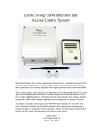
Estate Swing GSM Intercom and
Access Control System
Web Direct Brands, Inc., parent corporation of Estate Swing, warrantees all parts of the
Estate Swing GSM Intercom / Access Control System for a period of 1 year from the
date of purchase. The warranty applies to the original purchaser and is non-transferable.
The warranty applies only to defects in components and workmanship and NOT to damage due to causes beyond the control of Estate Swing; such as but not limited to incorrect voltage, lightning damage, mechanical shock, water damage, fire damage, damage
arising out of abuse and improper application of the equipment, or any acts of nature.
To address a warranty issue please call 1-800-640-4283 between 9-5 EST M-F to receive technical assistance and if deemed needed an RA number from a technician to
send the product or component in for evaluation. All RA must be returned with the RA
number on the outside of the package and with pre-paid postage.
Estate Swing
13100 State Road 54
Odessa, FL 33556
Introduction and Features
Call Button for visitors: The Estate Swing GSM intercom comes with a reception box
that a guest can call the resident from. The call button on the box, when pressed, directs
the system to dial the phone number of first administrator. If there is no answer the system will proceed to call the second and then third administrator numbers (if second and/
or third administrators exist).
Can hold 1000 authorized numbers: The Estate Swing GSM intercom can be programmed with up to 1000 phone numbers that are authorized users. These users will be
able to call the gate GSM phone number and when their phone number is recognized by
caller id as an authorized user the gate will open. The call is never answered by the
GSM so no minutes are used in this process.
Open the gate with your phone: As an administrator you have many opening options
for your gate.
• When you receive a call from a visitor you can open your gate from your phone.
• When entering the property yourself you can open the gate through a phone call to
the gate or an SMS text message to the gate.
• When entering the gate, if you wish to hold the gate open longer than its normal
pause time, for long trailers or trucks for example, you text a 1 time longer delay and
after the one opening it will go back to normal operation automatically.
• If you want to leave the gate open, you can enter party mode and text the gate to stay
open until it is texted again to close it.
Remote programming from phone: The Estate Swing GSM intercom can be programmed by an administrator from their phone through a call or text message. You can
do this from any location. The system will return conformation of successful programming through an audible confirmation by phone or a text conformation if programmed
by text message.
Visual Diagnostic Screen Plug-in: The Estate Swing GSM intercom comes with a diagnostic screen you can plug into the control board to see battery charge, signal strength
and see visual confirmations of programming being performed.
Battery Backup: The Estate Swing GSM intercom comes with a built in battery
backup. In the event of a loss of incoming power the system will automatically switch to
battery backup. The administrators can also have an option turned on to be notified
through text message of the system switching to battery back up so they can address the
lack of incoming power issue. The back up battery will last approximately 8 hours.
Installation of Components
Speaker/Microphone box:
• Take the screw out of the bottom of the box.
• The face of the speaker/mic box lifts straight off, it does not slide down.
• One the face is off you will see two screws holding the mid plate to the rear housing. Remove those
screws.
• There are 4 mounting holes in the rear housing, use flat head screws (not provided) to mount the rear
housing to a pillar, post or fence (not provided).
It is suggested to put a dab of silicone over and around the heads of the screws to keep insects and
moisture out.
• Run the 4 colored wires through to a junction box (not provided) and splice or use wire nuts to
lengthen the wire to reach your intercom control box (wire is not provided—use up to 22 gauge wire
up to 200’)
Reassemble the mid plate and the face plate.
Intercom Control Box:
• Inside the box you will find a wire with a coaxial connector and a red rubber cap.
Remove the rubber cap, nut and washer. [A]
Feed this through the hole on the lower right side of the box.
Put the nut and washer on the threads until it is secure against the side of the box.
Screw the antenna on the threads; there will be some visible thread on the coaxial connector even after the antenna is secured.
• You were provided two water tight wire connectors. Remove the back nut on the connectors and feed
through the two large holes on the bottom of the board.
Tighten the nuts back on the threads until it is snug against the box wall.
When you run your wire, do so through these connectors and tighten the connector down on the wire
to keep water and insects out.
• In the upper left hand corner, under the board, there is a backup battery. Find the red and black wires
with the connector on the end. [B]
Plug the backup battery into the board when you are done with your wiring, it is easier to fish the
wires out however before mounting the box.
• Mount the control box in a secure location near the gate opener control box.
• The intercom control box will have 4 wires coming into it from the speaker/mic box, 2 wires coming
in for power and 2 wires going out to the gate opener. (this is for minimum installation—additional
wires may be used in more advanced installations)
See the chart on the next pages for wire locations and power instructions.
[A]
[B]
Wiring
Speaker/Microphone box to Control Box:
• Black wire to terminal 10
• Red wire to terminal 11
• Green wire to terminal 12
• Yellow wire to terminal 13
• Run between speaker/mic box and control box should not exceed 16’
Control Box to Gate Opener:
• E-S 1100, E-S 1102, E-SC 1102, E-SL1200
Terminal 4 of intercom to Terminal 13 of gate opener
Terminal 16 of intercom to Terminal 1 of gate opener
•
E-S 1600, E-S 1602, E-SC 1600, E-SC 1602, E-SU2200, E-SU2202, E-SL 1800
Terminal 4 of intercom to Terminal COM of gate opener
Terminal 16 of intercom to Terminal OPE9 A of gate opener
•
E-S 300, E-S 302, E-S 500, E-S502
Terminal 4 of intercom to Terminal P1of gate opener
Terminal 16 of intercom to Terminal V+ of gate opener
Power Connection & Sim Card:
Low voltage power connection:
• Verify the On/Off switch is in the OFF position (LEFT)
• In the bottom of the box you will see a red and black wire attached to a round connector. You will
utilize this connector for your low voltage connection. Cut the red and black wire about 2 - 3 inches
from the round connector.
• Using low voltage wire (16-20 gauge stranded direct burial 2 conductor) up to 500 feet connect the red
wire of the connector to the positive and the black to a negative of a 12 - 24V DC transformer. The
wire connections can be made using wire nuts inside the control box.
• Plug in the back up battery (upper right side of board, white connector) and plug in the round low
voltage connector.
• Do not turn the On/Off switch
to On until specified by the
directions.
SIM Card:
• Slide back the SIM door and
it up
• Slide the SIM card into the
SIM door making sure that the
clipped corner of the SIM card
lines up with the clipped corner
the SIM holder
lift
of
Powering up/Verification of system ready:
Digital Diagnostics Board:
The plug in LED board that comes with the unit is for diagnostic purposes. It is recommended that you
have the installed when you first turn on the system so you can check your system statuses. After you feel
confident with programming or when you close the control box; take the diagnostic display off the
board and store it in a safe dry location.
Turn System on:
• Flip the On/Off switch to the right.
• ATT9: When you first turn the system on the system will actuate the gate. Stand clear of the
gate.
Once you turn on the system you will see the following
Now the system is ready for programming.
Programming Administrator umbers:
Administrator codes:
Administrators can program the system, open the gate via cell phone and receive the phone calls from the
gate call box.
Programming via phone call:
The administrator numbers can be programmed individually or all in
Diagnostic display read out below
one call
using the following [Example numbers are (1111558888),
(2222669999), and (3333770000) - substitute real phone numbers in your programming]. Only
one administrator needs to be established to begin using the system.
Example:
Once the call has connected… (With a short beep ~ prompt the administrator to enter password, the initial set up password is 123456
by default)
After enter password… (Another short beep ~ Password Correct)
Press *3# (you should hear a short beep ~ success)
Continue press 1# to add the first administrator number (another
short beep ~ success)
Then enter the administrator number 1111558888# (you will hear a
short beep ~ the administrator number is setup successfully)
Continue...
Press *3# (you should hear a short beep ~ success)
Continue press 2# to add the second administrator number (another short beep ~ success)
Then enter the administrator number 2222669999# (you will hear a short beep and the number has been
changed to 2222669999
Continue...
Press *3# (you should hear a short beep ~ success)
Continue press 3# to add the third administrator number (another short beep ~ success)
Then enter the administrator number 3333770000# (you will hear a short beep and the number has been
changed to 3333770000
If the change has not been successful you will hear 3 beeps and must re-enter again.
Programming via Text Message (SMS) on next page.
Programming Administrator umbers (cont):
Programming via Text Message (SMS)
Send the following 3 SMS Commands:
1) *TEL1#1111558888
2) *TEL2#2222669999
3) *TEL3#3333770000
As the first 2 numbers will be the customers own numbers you would program in the Installers number in
*TEL3#
This number can be changed once the system has been installed.
When the system received the message and the number is programmed successfully, it will display “OK”
on the screen and the administrator will receive a reply message from the unit.
Example of Return Message:
TEL1=1111558888
TEL2=2222669999
TEL3=3333770000
To change an administrator number you can simply SMS or call and write over the TEL#. You have to be
an administrator to do this.
Phone Call From Gate
When a person presses the call button at the gate the #1 administrator will receive a phone call from the
front gate.
If they do not answer it will roll to the #2 and then to the #3.
______________________________________________________________________________________
In order to open the gate through Relay 1 (this is the primary relay that is normally hooked to the
gate opener) the administrator should press:
*0#
_________________________________________________________________
In order to open a secondary device through Relay 2 (this is the relay that is normally hooked to a pedestrian gate lock or other device) the administrator should press:
*1#
In order to disconnect the call from the gate without opening the gate (this would be if you did not want to
let the person in) the administrator should press:
*4#
This can also be used before hanging up after opening the gate to be sure that the network doesn’t hold the
call from the gate and waste minutes.
Changing Administrator Pass Code from Default:
Programming via phone call:
The system only allows the 3 administrator numbers as authorized user to change the 6 digits password.
To change the password from the factory default 123456 to 654321 (Example) you can just call the unit and when the unit replies,
you can use the following commands using the keypad prompts on your telephone.
Once the call has connected … (With a short beep ~ prompt the administrator to enter password, the initial set up password is
123456 by default)
After enter password… (Another short beep ~Password Correct)
Press *2# (A short beep ~ success)
Then input the current password 123456# (you should hear a short beep ~success)
Continue to enter new password 654321# for 2 times (another short beep if password entered correctly)
If the change has not been successful you will hear 3 beeps and must re-enter again.
Programming via Text Message (SMS)
Example:
Sends a SMS Command: *PAWO#654321
If the change is successfully, the system will display “OK” on the screen and the administrator will receive a reply message from
the unit.
Returned Message:
PAWO-OK
Resetting forgotten password
In the event the password is forgotten or cannot be accessed, you can send the following SMS to the unit and the system will be
reset to factory default as *123456#
Sends the SMS Command *REST#615858 and the unit will reply REST-OK and the password is now back at factory default as
*123456#
To manually reset the unit, you can press and hold on the “Call” button and turn on the unit for 10 seconds. The unit will displays
Wait… and then OK, the unit is reset.
Programming User Access Phone umbers:
IMPORTA9T—PLEASE READ FIRST
User access numbers can open the gate by calling the gates phone number and the call id of the unit will
recognize their number and open the gate for them. In order for the system to rapidly sort recognized numbers it stores them in lists 0 through 9. There is the ability to keep up to 99 numbers in each list. It will be
much easier if you organize your phone numbers by list and slot number before programming. The last digit
of the phone number determines its list. Example: if the number ends in 2 then the number has to be in list
to. The slot number (01-99) in list 2 is up to you.
Example of a user list
List 0
none
List 1
Slot 1
Slot 2
684-727-1991
305-700-2261
jack
larry
List 2
Slot 1
734-253-5832
mel
List 3
Slot 1
813-343-0913
karen
List 4
none
List 5
none
List 6
Slot 1
Slot 2
Slot 3
312-348-6546
422-311-9846
422-875-2116
helen
troy
steve
list 7
Slot 1
813-945-8537
tom
List 8
Slot 1
213-253-9748
sue
List 9
none
Programming User Access Phone umbers (cont):
Programming via phone call:
To program [Example number 2222222226 into position 03] in the list:
Diagnostic display read out below
Press *5# (A short beep ~ success)
Continue press 603 (you should hear a short beep ~success)
Then you can input the phone number 2222222226# (A short beep ~ success)
Guest:6>03;
And 2222222226 is programmed into position 03 in list 6
Guest:6>03;
ote: If the last digit guest number entered was not match with the list number, the
number will not program successfully.
2222222226
If the change has not been successful you will hear 3 beeps and must re-enter again.
Programming via Text Message (SMS)
Example:
To program phone number: 3333333331
Sends SMS command *BOOK#01#3333333331
Hence 33333333331 is listed in position 01 in List 1
Returned Message: BOOK(1>01;)= 3333333331
For phone number: 4444444441
Sends SMS command *BOOK#02#4444444441
Hence 4444444441 is listed in position 02 in List 1
Returned Message: BOOK(1>02;)= 4444444441
Deleting a number via Text Message (SMS) [can only be done through text]
Example:
To remove phone number: 6666666667
Simply sends a SMS Command *DEL>#6666666667 to the unit and it will search for number (6666666667) in the list and delete
it.
Returned Message:
Delete-OK
Alternate Relay Activation:
Activating relay 2:
There is a second relay which can control another device like a pedestrian gate. You can activate it using
text messaging from an administrator phone. (as well as relay 1)
Send either of the the following 2 SMS Command:
1) *ECL1#
2) *ECL2#
Returned Message:
ECLK1<OK>
ECLK2<OK>
Party Mode:
You can latch relay 1 or 2 to stay on until commanded to turn off, which can be used to open the gate and
hold it open.
Send either of the following 2 SMS Command:
1) *FRL1#1 – Latch Relay1 to stay ON
2) *FRL2#1 – Latch Relay2 to stay ON
Returned Message:
FRL1<O9>
FRL2<O9>
Send either of the following 2 SMS Command to turn OFF:
1) *FRL1#0 – Switch OFF Relay1
2) *FRL2#0 – Switch OFF Relay2
Returned Message:
FRL1<OFF>
FRL2<OFF>
Alternate Relay Activation (cont):
Temporary longer latch:
You can extend the time the gate pauses in the open position by extending the relay latch time for a single
use. This is helpful if you are driving a slow moving or long vehicle. It can be held for up to 65000 seconds.
Via phone call:
Once the call has connected… (With a short beep ~ prompt the administrator to enter password, the initial set up password is
123456 by default)
After enter password… (Another short beep ~ Password Correct)
Press *6# (A short beep ~ success)
Continue press 1# for relay 1 (A short beep ~ success)
Then input value 00030# (A short beep ~ success)
Relay 1 will now latch for 30 seconds and after 30 seconds it will switch off and sends a message back to the administrator informed that Relay 1 has closed.
Via text message (SMS):
Example:
Temporary latch Relay 1 for 60 seconds or
Temporary latch Relay 2 for 180 seconds
Simply send either of the 2 SMS command as below:
*RLY1#00060
*RLY2#00180
Example of Returned Message:
RELAY1=00060
RELAY2=00180
Special Functions:
Admin and user access:
It is possible to control the access of administrator or user to the system by sending the following SMS command to the unit.
Sending SMS Command *A9Y?#1, the system will allow only the administrators to gain access to the system and the authorized
users in this case will not allow to access the system. (Factory Default: *A9Y?#0 ~ Any person can gain access to the system)
9ote: It is advised that the owner should set the system to allow access only for administrators after programmed the Administrator numbers.
Sending SMS Command *TEL?#1, the system will 9ot receive phone call from both administrators and users but will activate
relay 1 immediately. (Factory Default: *TEL?#0 ~ able to receive phone call only from administrator but will not activate relay
1 immediately)
Text Reporting to Admins:
It is possible to turn ON/OFF the request of report message when inputs triggered from the unit by sending the following SMS
command to the unit.
Example of sending the below command:
*RER9#100 (Factory Default)
Only Administrator number 1# will receive a report message after setup
Returned Message:
RER9:<100>
*RER9#110
Administrator number 1# and 2# will receive a report message after setup
Returned Message:
RER9:<110>
*RER9#111
All the Administrators will receive a report message after setup
Returned Message:
RER9:<111>
Sending the below command will turn Off this feature:
*RER9#000
Special Functions (cont):
Check signal strength:
To check the signal strength (0-31), you would send the following SMS command to the unit.
*CSQ?#
Example of Returned Message:
CSQ=<27>
Power Loss Report:
The unit is able to send alert message to the administrator in the event the main power is out / turned off. When the main power is
restored it can notify the administrator again the main power is on.
When main power OFF
The unit will send a message: ACP-OFF
Note: At the same time, it will send an ALWAYS high pulse out from I/O port. Alarm will sound.
When main power restored
The unit will send a message: ACP-O9
Intercom Volume:
It is possible to adjust the volume (from level 1 to 6) of the intercom by sending the following SMS command. Factory Default:
4
Example: Sending the following SMS Command
*SOUD#5 – Adjust the volume to 5
Example of Returned Message:
SOU9D:<5>
Remote System Check:
It is possible to check the system is operating correctly by sending the following SMS command to the unit.
Send the following SMS Command:
*TEST#
When the unit replies TEST-OK indicate the unit is operating correctly.
9ote: If you receive no reply then unit is not working
Trouble Shooting:
An alarm keeps sounds repeatedly and/or power loss text keeps being sent after switching
unit on:
•
Check to be sure the transformer is a DC transformer. AC power will repeatedly turn the power on and off and
create multiple text messages. AC power may also do irreversible damage to the control board.
Text messages are not being returned:
•
Turn the power off for 5 seconds and then turn back on. This will reconnect your SIM card with the network.
•
Check to see who is an administrator, if you are no longer an administrator you will not receive text notifications.
•
Check to see what # administrators are programmed to receive notification; if any at all. (under special functions)
I need to reset my entire unit:
•
Turn the unit off. Plug in the digital read out. Press and hold the “Call” button on the gate. Turn the unit back
on and wait approximately 10 seconds while holding the call button on the unit. The unit display will read
“Wait…” and when finished will read “OK”. At this point the unit is reset and your password is returned to
*123456#
I cannot get my SIM card to react to programming:
•
Many SIM cards have an initial 4 digit security PIN code. This must be disabled. This can be done by placing
the card in an unlocked cellular phone and checking to see if the SIM requested a PIN. If there is a PIN requested, it can be disabled through the phones security settings.