1
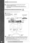
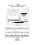
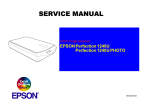
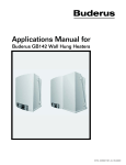
PowerView™ Model AP9215 User’s Manual Thank You ! Thank you for selecting the American Power Conversion PowerView. It has been designed for many years of reliable, maintenance-free service in combination with your American Power Conversion Uninterruptible Power Source. American Power Conversion is dedicated to the development of high-performance electrical power conversion and control products and we hope that you will find this product a valuable, convenient addition to your computing system. Please read this manual! It provides important installation and operating instructions that will help you get the most from your PowerView. Save this manual! It includes instructions for obtaining factory service should the proper operation of the accessory come into question.. Contents Introduction ............................................................. 2 Supported UPS Models ......................................................2 Controls and Indicators ..................................................... 3 Installation ............................................................... 4 General Navigation .................................................. 5 Menu Structure ......................................................... 6 Control .............................................................................. 7 Status ................................................................................ 8 Setup ................................................................................. 9 Accessories ..................................................................... 11 Logging .......................................................................... 12 PowerView Information and Configuration .................... 13 Diagnostics ..................................................................... 14 Help ............................................................................... 14 Replacing the Language EPROM ............................. 15 Mounting Template ................................................ 16 1 Introduction PowerView is a compact control panel and display which provides full control, monitoring and configuration of the connected UPS. Figure 1 PowerView Front Panel Supported UPS Models PowerView supports the following APC UPS model families: Smart-UPS: SU450, SU700, SU1000, SU1400, SU2200, SU3000 Matrix-UPS: all models Symmetra: all models The following APC UPS families are not supported by PowerView: Back-UPS: all models Smart-UPS: AP250, AP400, AP600, AP900, AP1250, AP2000, SUVS420, SUVS650, SUVS1000, SUVS1400, SU420, SU620 2 Controls and Indicators Indicators Figure 2 Front Panel Indicators LOAD ON: Indicates that the load connected to the UPS is receiving power (On-line, On-Battery or Bypass). ON BATT: Indicates that power to the attached load is being supBYPASS: FAULT: plied by the UPS’s batteries (unavailable while in Bypass). Indicates that power to the attached load is being supplied through the UPS’s filtering and surge suppression circuits directly. The UPS will not power the load from battery in the event of a power failure. (This feature is available only on Matrix-UPS and Symmetra models). Indicates that the UPS has detected a problem or certain configuration changes (includes both hardware failures and abnormal conditions such as overload or over temperature). Controls The control keys are used to navigate between menus, to select menu items, and to input alphanumeric information. The section entitled General Navigation on page 6 provides additional information. Figure 3 Control Keys 3 Installation PowerView is connected directly to the UPS through a single interface cable (PN 940-0110) included with the PowerView unit. Follow the steps below to connect PowerView to the UPS: 1. Connect the modular RJ45 plug on the end of the interface cable to the connector at the rear of PowerView. 2. Check the rear of the UPS to determine whether there is a cable already connected to the 9-pin computer interface connector. If there is a cable already connected to this connector, shut down any UPS monitoring software running on the host system, then loosen the thumb screws and remove the existing cable. If there is no cable connected, continue with Step 3. 3. Connect the male end of the 940-0110 cable to the computer interface connector at the rear of the UPS and secure it with the thumbscrews. 4. If it was necessary to remove a cable in Step 2, connect the removed cable to the female connector on the 940-0110 cable and tighten the thumb screws. If no cable was removed, the unused connector may be left unconnected. PowerView may be mounted to the wall with screws using features on the back or it may be mounted with the supplied hook and loop fasteners. A template for mounting PowerView to the wall is supplied at the end of the manual. PowerView will also sit upright on a flat surface by folding out the wire bail on the rear of the unit. Figure 4 4 PowerView Interface Cable General Navigation Note: Throughout this manual the four navigation keys will be represented as: Esc, , , and Enter ( ). Specific menus are referenced in the form Display:Password where Display refers to a menu item in the top-level menu and Password refers to a submenu of Display. The default screen will appear when PowerView is first powered on or after any extended period of inactivity. Pressing any key will access the top level menu. When in any menu, pressing or will move the cursor ( ). The Enter key ( ) will advance you deeper into the menu tree. The Esc key will back out to the parent menu. The menu tree is outlined in the following pages. For status or information screens there is no cursor, the or keys act like page up/down keys to show multiple screens, if appropriate. For settings menus, point ( ) to a parameter and press Enter ( ); the cursor will move adjacent to the parameter value and become a . The or keys will now increment or decrement the value. The value displayed takes effect immediately. When the desired value is displayed, press either Esc or Enter ( ) to exit the selection mode. (Both Esc and Enter ( ) have exactly the same function in this case.) Pressing and simultaneously will display context sensitive help on most screens and menus. Note that control and configuration functions can be password protected (see the Display:Password menu). Also, the ‘default’ screen is user configurable (see the Display:Config menu). 5 Menu Structure PowerView’s menu structure is divided into eight(8) functional groups. These groups are: • Control • Status • Setup • Accessories • Logging • PowerView Information and Configuration • Diagnostics • Help The functions and status information available for each of these groups is outlined in the following pages. 6 Control n UPS On/Off n Do Self Test – UPS verifies proper system operation by briefly powering the attached load from battery. n Simulate Power Fail – causes UPS signaling port to immediately indicate that the AC line has failed. This may initiate an orderly server shutdown sequence if the appropriate cable and software drivers are used. n Graceful Reboot – initiates an orderly server shutdown and restart sequence if the appropriate cable and software drivers are used. The sequence is: 1. The UPS signaling port indicates that the AC line has failed and that the UPS battery is low. (Server will quickly begin shutdown if so configured.) 2. After the Low Battery Duration time plus the Shutdown Delay time (user settable parameters in Setup:Shutdown) the UPS will turn off for the Return Delay time (user settable parameter in Setup:Shutdown) then come back on unless: (1) the input AC line voltage is out of tolerance or (2) the battery capacity is below the Return Battery Capacity (user settable parameter in Setup:Shutdown). n Graceful Turn Off – same as Graceful Reboot above except that the attached load remains off until turned on by the user via the Control:Turn Load ON command. n Start/Stop Runtime Calibration – causes UPS to run on battery until the battery(s) is(are) discharged to approximately 25% of capacity. Data recorded during this time improves the accuracy of the Runtime estimate which the UPS reports in the Status screen. Recommended testing interval: once per month. n UPS into/out of Bypass (Matrix and Symmetra only) — When bypassed, power to the attached load is being supplied through the UPS’s filtering and surge suppression circuits directly. The UPS will not power the loadfrom the battery in the event of a power failure. This is generally used during maintenance on modular UPSs. 7 Status n Status Display 1 Input Line Voltage and Frequency Output Voltage Runtime Estimate Load (in Amps and % of VA capacity) n Status Display 2 UPS internal temperature Last Transfer: the cause of the most recent on-battery event. None the UPS has not been on battery recently. Test a self-test caused the UPS to briefly run on battery. Notch/Spike - AC line voltage was non-sinusoidal or severely distorted; includes total power failure. Low Voltage - AC line voltage went below the lower transfer point. The lower transfer point is user adjustable in certain UPS models, see Setup:Transfer menu. Hi Voltage AC line voltage exceeded the upper transfer point. The upper transfer point is user adjustable in certain UPS models, see Setup:Transfer menu. Rate of Chng - abrupt change in line voltage CirBrkr Trip - input circuit breaker tripped (Symmetra only) Status: a terse indication of the state of the UPS. The most common are On-Line (AC line quality is acceptable), UPS/ Load off, On-battery (load is powered from battery), LowBattery (battery is fully discharged), Overload, or any one of a number of internal faults. Use Diagnostics from the top level menu for a detail of the UPS status and faults. Number of installed batteries and bad batteries (Matrix-UPS and Symmetra only) 8 n Status Display 3 Battery voltage % Battery Capacity Result of last Selftest: None – no recent selftest OK – most recent selftest was satisfactory Unavail – unavailable Can’t Tst – UPS could not perform the test at the time. Failed – battery condition has deteriorated below a reliable level, the battery should be replaced. Setup n Transfer – these first three parameters control when the UPS switches to battery. Low Xfer (Lower transfer voltage) – the output voltage at which the UPS switches transformer taps or onto battery. High Xfer (High transfer voltage) – the output voltage at which the UPS switches transformer taps or onto battery. (If you notice that the input voltage is generally close to one end of the lower/upper voltage window, it may be necessary, depending on the load’s voltage requirements, to recenter the window by changing the lower and/or upper transfer voltages) Sensitivity – sudden, small changes in input voltage will cause the UPS to briefly run on battery. (If you notice, or the event log indicates, that the UPS transfers to battery frequently, it may be necessary, depending on the load’s voltage requirements, to lower the sensitivity one step at a time. If the UPS still transfers frequently, check the lower/upper transfer voltage window described above). Output (only on 220/230/240V UPSs) – allows selection of nominal output voltage. 9 n Shutdown – these parameters affect signaling via the UPS’s interface port. They are generally used in the context of controlling an orderly shutdown of an attached server in the event of a power failure or a user initiated Graceful Reboot or Graceful Off. Low Battery Duration – length of time between low battery signalling and shutdown of power to the attached load. (Set this for long enough to allow the server to perform its shutdown process) Shutdown – The length of time between a shutdown command (from the computer to the UPS) and shutdown of power to the attached load. This is to allow a server time to gracefully complete its shutdown process. Return Delay – the minimum length of time that the UPS will wait before restoring power to the attached load after return of normal line voltage. Note: the UPS may wait longer than this if the battery capacity is less than the value of Return Battery Capacity. Return Battery Capacity – The minimum percentage of battery capacity required before power is restored to the attached load after return of normal line voltage. n Other Self Test – The UPS can be configured to perform a selftest automatically at selectable time intervals. UPS ID – the user can store up to 8 characters of descriptive text in the UPS for identification purposes. This setting has no effect on the operation of the UPS. Allowable characters are: A-Z, 0-9,/, space. Battery Date – Set at the factory to the date the battery was installed (mm/dd/yy format). If the user replaces the battery, the date should be updated for future reference. This setting has no effect on the operation of the UPS. Allowable characters are: 0-9,/, space. External Battery Packs – in SmartUPS which have external batteries (having XL in the model number), the user must tell the UPS how many external battery packs are attached so that the Runtime estimate will be correct. This is important not only for the displayed runtime estimate but also for the Low Battery Duration time (advance warning of impending discharged battery). 10 n UPS Information Display Model Name Firmware Revision Level Serial Number Manufacture Date n Copy – PowerView can ‘learn’ the configuration of a UPS and subsequently write that data to the same or a different UPS. Up to five UPS configurations can be stored in PowerView’s memory. First select the configuration that you wish to move UPS data into or out of, then select the direction that you wish to move the data. Copying data between different voltage versions may not yield optimum results; in particular, the output voltage selection should be reviewed by the user. Copying between different product lines may leave some parameters in the target UPS set to factory defaults, especially when copying from a product with less capability to one with more capability. Configuration number From UPS to Display From Display to UPS Accessories APC sells accessories which plug into the back of the UPS, such as environmental monitors and power control devices. If supported accessories are installed, status and setup menus are found here. n Measure-UPS II Probe 1 or 2 status display Ambient Temperature and Humidity Upper/Lower alarm limits for Temperature and Humidity Probe 1 or 2 setup Upper/Lower alarm limits for Temperature and Humidity Zone Status – shows the states of the 4 inputs as normal or alarm. 11 Logging PowerView keeps a log of up to 64 of the most recent events. The user can clear the log and ‘filter’ certain event types from being logged. n View Log – the points to an event; the date, time and number of that event are displayed on the top line. Event 1 is the oldest. Press Enter ( ) for a more verbose description of the event. The and keys scroll through events. Press Esc to revert back to three event viewing. n View Statistics – an absolute count of events witnessed by PowerView. Transfers to Battery Low Battery (battery must be fully discharged to be counted) Faults or abnormal conditions Total accumulated runtime on battery n Configure Logging – see the List Event Groups screens to see what events each category includes. Logging of each event group may be individually enabled or disabled. Power Events UPS Control UPS Faults User Activity Measure-UPS Events n List Event Groups Power Events UPS Control Events UPS Faults User Activity Measure-UPS events n Clear Log 12 PowerView Information and Configuration n Set current date and time (used for log entries) n Password – when a non-null password is configured, all control and configuration functions provided by PowerView will require the user to enter the password. The default from the factory is no password. Set password – press enter and use the and keys to set a character string of up to 8 characters. The underscore ( _ ) character is used to indicate the end of a password that is less than 8 characters in length. Setting the first character of the password to underscore disables password protection. Allowable characters are: A-Z, 0-9,/, space. Password timeout – a period of user inactivity greater than this value will require re-entry of the password. The length of inactivity before PowerView reverts to the default data screen is also determined by this setting. Invalidate (timeout) the password immediately – any sucessive attempt at control or configuration functions will require entering the password. n Information about PowerView Model Number Serial Number Manufacture Date Hardware and Firmware Revision Levels n Beeper Settings At UPS – condition when the UPS will beep At Display – condition when PowerView will beep Beeper Volume Key click on/off n Contrast – adjust for optimum viewing of display. 13 n Configuration of default screen – After selecting this option, the screen will appear as the default data screen with the exception of a cursor in the upper left corner. The and keys will select the line that you wish to change. Pressing Enter ( )changes the cursor to and the and keys will now select the contents of that line. Press Enter ( ) once selection is made. Diagnostics If there are multiple faults or abnormal conditions, pressing any key will move through the list. Help Pressing and simultaneously will display context sensitive help on most screens and menus. 14 Replacing the Language EPROM PowerView can be configured to display text in a language other than the default English by replacing the unit’s language EPROM with one of the alternate language EPROMs included with the unit. Follow these steps to replace the unit’s language EPROM: Note: The device being replaced is static sensitive. Do not remove it from the protective carrier until you are ready to insert it in the unit. 1. Remove the four (4)Phillips screws on the rear of the unit and separate the front half of the case from the rear. 2. Identify the language EPROM. This is a 28-pin integrated circuit located in a socket and adjacent to the large 40-pin device. The language EPROM will have a white label bearing the name of the language for which it is programmed. Note which end of the EPROM has the semicircular notch (pin 1); the new EPROM must be installed with the same orientation as the original. 3. To remove the EPROM, insert a small screwdriver or similar tool between the EPROM and its socket. Gently twist the blade to lift the EPROM from the socket. In order to avoid bent pins, the EPROM should be loosened gradually, one side at a time, until it is free of its socket. 4. Position the new EPROM on its socket with the notch in the same relative position as the original. Carefully check that all pins are aligned with the socket. Realign if necessary. Apply even pressure with fingers to the top of the EPROM until it is fully seated in its socket. 5. Replace the rear cover and re-install the four (4) Phillips screws. Figure 5 Location of Language EPROM 15 Mounting Template Figure 6 16 Wall Mounting Template Toll free technical support: Addresses: United States and Canada 1-800-800-4272 Ireland 1-800-702000 U. K. 0800-132990 American Power Conversion Corporation 132 Fairgrounds Road P. O. Box 278 West Kingston, Rhode Island 02892 USA In areas without toll free numbers, call: +1 401 789 5735 (USA) or +353 91 702020 (Ireland) American Power Conversion Corporation (A. P. C.) b. v. Ballybritt Business Park Galway Ir eland Serial number: Entire contents copyright © 1997 American Power Conversion. All rights reserved; reproduction in whole or in part without permission is prohibited. PowerView is a trademark of APC. All other trademarks are the property of their respective owners. 990-0142 Rev. 1 07/97