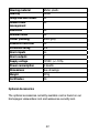
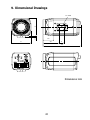
1
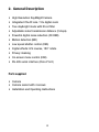
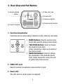
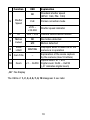
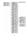
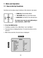
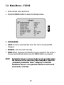
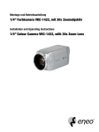
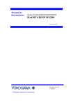
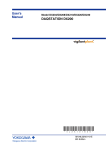
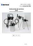
Installation and Operating Instructions
1/4” Camera, Day & Night, 23x Zoom
VKC-1425
Contents
1. Safety Instructions.......................................................................4
2. General Description.....................................................................6
3. Rear View and Part Names..........................................................7
4. Installation..................................................................................9
4.1 Connecting a Monitor.........................................................9
4.2 Connecting to Power........................................................10
4.3 Camera Control Methods..................................................11
5. Communication Protocol............................................................14
5.1 PELCO-D Byte Format.......................................................14
5.2 PELCO-P Byte Format.......................................................16
6. On-Screen Display.....................................................................17
6.1 Explanation of the On-Screen Display...............................17
7. Menu and Operation..................................................................20
7.1 How to Set Up Functions..................................................20
7.2 Main Menu – FOCUS........................................................22
7.3 Main Menu – EXPOSURE..................................................24
7.4 Main Menu – DAY/NIGHT (optional)...................................26
7.5 Main Menu – BLC.............................................................27
7.6 Main Menu – WHITE BAL..................................................28
7.7 Main Menu – 3D-DNR......................................................29
7.8 Main Menu – SPECIAL......................................................30
7.9 Main Menu – GENERAL....................................................35
7.10 Main Menu – INITIAL........................................................38
7.11 Main Menu – EXIT............................................................39
8. Specifications............................................................................40
9. Dimensional Drawings...............................................................43
Betriebsanleitung
Installation and Operating Instructions
Mode d’emploi
Instrukcja instalacji i obsługi
⇒
www.videor.com
www.eneo-security.com
1. Safety Instructions
• Read these safety instructions and the operation manual first before you install and commission the camera.
• Keep the manual in a safe place for later reference.
• P rotect your camera from contamination with water and humidity
to prevent it from permanent damage. Never switch the camera on when it gets wet. Have it checked at
an authorized service center in this case.
• Never operate the camera outside of the specifications as this may prevent the camera functioning.
•
Do not operate the cameras beyond their specified temperature, humidity or power ratings. Operate the camera only at a temperature range of -10°C to +50°C and at a humidity of max. 90%.
• To disconnect the power cord of the unit, pull it out by the plug. Never pull the cord itself.
• P ay attention when laying the connection cable and observe that
the cable is not subject to heavy loads, kinks, or damage and no
moisture can get in.
• The warranty becomes void if repairs are undertaken by unauthorized persons. Do not open the camera housing.
• Never point the camera towards the sun with the aperture open. This can destroy the sensor.
• Installation, maintenance and repair have to be carried out only by authorized service centers.
Before opening the cover disconnect the unit from mains input.
• The fitter is responsible for the system of protection being followed in accordance with the technical data, e.g. by sealing of the cable outlet with silicone.
• Contact your local dealer in case of malfunction.
• Only use original parts and original accessories from Videor E. Hartig GmbH.
•
Do not use strong or abrasive detergents when cleaning the dome. Use a dry cloth to clean the surface. In case the dirt is hard to remove, use a mild detergent and wipe gently.
•
During assembly, care must be taken to ensure that existing
seals are correctly inserted and are not displaced as a result
of assembly.
You must not continue to use damaged seals.
NOTE:
This is a class A digital device. This digital device can
cause harmful interference in a residential area;
in this case the user may be required to take
appropriate corrective action at his/her own expense.
2. General Description
• High Resolution Day&Night Camera
• Integrated 23x AF lens / 10x digital zoom
• True day&night mode with IR cut filter
• Adjustable video transmission distance (3 steps)
• Powerful digital noise reduction (3D DNR)
• Motion detection (MD)
• Low speed shutter control (DSS)
• Digital effects: H/V reverse, 180° rotate
• Privacy masking
• On-screen menu control (OSD)
• RS-485 serial interface (Pelco P & D)
Parts supplied
• Camera
• Camera socket with 4 screws
• Installation and Operating Instructions
3. Rear View and Part Names
(2) Video Out Jack
(1) Function Setup Button
(3) Power LED
(4) Selection Switch
(5) Power Input Terminal
(6) Control Terminal
1. Function Setup Button
Functions can be setup using 5 buttons on the camera’s rear panel.
• MENU Buttons: Used to access menu mode. Also used to escape menu mode.
•
TELE/WIDE Buttons: Used to choose the desired menu item. It also moves the cursor up or down in the menu screen.
•
NEAR/FAR Buttons: Used to change the parameter of the selected menu item. It also moves the cursor the left of right in the menu screen.
2. VIDEO OUT Jack
Used to connect an external video monitor in jack
3. Power LED
The LED turns on when power is supplied.
4. Selection Switch
When the distance is far from camera to monitor, set „Selection Switch” in 2 or 3. It shows more clear video on the monitor.
5. POWER Input Terminal
6. Control Terminal
• D&N IN: It is the function that can turn on external D&N mode is set „EXT D&N” on the OSD menu of the camera.
D&N IN
GND
EXT Type
SW
Open contact: Day
Close contact: Night
• MD OUT: It is the function that can turn on DVR recorder when MD mode is set „ON” on the OSD menu of the camera.
MD OUT
GND
+5V
0V
+5V 10mA: Motion on
0V: Motion off
4. Installation
4.1 Connecting a Monitor
Connect the video out jack on the back of the product to the monitor
Camera
Monitor
• Connect the camera after switching off each piece of equipment.
•
Change the 75ohms/Hi-Z conversation switch of each piece of equipment according to the following diagram - move the switch of the intermediate monitor to Hi-Z, and the end equipment to 75ohms.
Camera
Intermediate Video receiver
End Equipment
4.2 Connecting to Power
• The wire is polarized. Be careful of polarity.
• Use 12VDC power source.
• As voltage may drop according to the length of electric cord,
a camera may malfunction if too long output line of adaptor
is connected to the camera.
• Voltage for camera operation: 12VDC ±10%
10
4.3 Camera Control Methods
Remote control using for PTZ controller
PTZ Controller
11
Remote control using for RS-485
Signal (RS-485)
DVR System
Pelco-D Keyboard
12
• DVR
DVR - Connect to Serial PORT (COM1 or COM2)
Serial Cable
Camera RS-485 Converter
• Keyboard (Pelco-D, Pelco-P)
Pelco-D Keyboard
13
5. Communication Protocol
5.1 PELCO-D Byte Format
-RS-485, 9600bps, 1 start bit, 8 data bits, 1 stop bit, no parity
• Command Message
Function
MSG
Zoom Tele
Byte 1
Byte 2
Byte 3
Byte 4
Byte 5
Byte 6
Byte 7
0xFF
CamID
0x00
0x20
0x00
0x00
Checksum
Byte 1
Byte 2
Byte 3
Byte 4
Byte 5
Byte 6
Byte 7
0xFF
CamID
0x00
0x40
0x00
0x00
Checksum
Byte 1
Byte 2
Byte 3
Byte 4
Byte 5
Byte 6
Byte 7
0xFF
CamID
0x01
0x00
0x00
0x00
Checksum
Byte 1
Byte 2
Byte 3
Byte 4
Byte 5
Byte 6
Byte 7
0xFF
CamID
0x00
0x80
0x00
0x00
Checksum
Byte 1
Byte 2
Byte 3
Byte 4
Byte 5
Byte 6
Byte 7
0xFF
CamID
0x40
0x00
0x00
0x00
Checksum
Byte 1
Byte 2
Byte 3
Byte 4
Byte 5
Byte 6
Byte 7
0xFF
CamID
0x88
0x00
0x00
0x00
Checksum
Byte 1
Byte 2
Byte 3
Byte 4
Byte 5
Byte 6
Byte 7
0xFF
CamID
0x08
0x00
0x00
0x00
Checksum
Byte 1
Byte 2
Byte 3
Byte 4
0xFF
CamID
0x00
0x00
Function
MSG
Zoom Wide
Function
MSG
Focus Near
Function
MSG
Focus Far
Function
MSG
Menu On / Off
Function
MSG
Power On
Function
MSG
Power Off
Function
MSG
Pelco D Stop
14
Byte 5
Byte 6
Don’t care
Byte 7
Checksum
• Pelco Keyboard (95 + Pattern)
Function
MSG
Menu On / Off
Byte 1
Byte 2
Byte 3
Byte 4
Byte 5
Byte 6
Byte 7
0xFF
CamID
0x00
0x23
0x00
0x5F
Checksum
• Video Keyboard (Set Preset + 98)
Function
MSG
Menu On / Off
Byte 1
Byte 2
Byte 3
Byte 4
Byte 5
Byte 6
Byte 7
0xFF
CamID
0x00
0x03
0x00
0x62
Checksum
15
5.2 PELCO-P Byte Format
-RS-485, 9600bps, 1 start bit, 8 data bits, 1 stop bit, no parity
• Command Message
Function
Zoom Tele
Byte 1 Byte 2 Byte 3 Byte 4 Byte 5 Byte 6 Byte 7
MSG
0xA0
CamID
0x00
Function
0x20
0x00
0x00
0xAF
Zoom Wide
Byte 1 Byte 2 Byte 3 Byte 4 Byte 5 Byte 6 Byte 7
MSG
0xA0
CamID
0x00
Function
0x40
0x00
0x00
0xAF
0xA0
CamID
0x02
Function
0x00
0x00
0x00
0xAF
0xA0
CamID
0x01
Function
0x80
0x00
0x00
0xAF
0xA0
CamID
0x80
0x00
Function
0x00
0x00
0xAF
0xA0
CamID
0x50
Function
0x00
0x00
0x00
0xAF
0xA0
CamID
0x40
Function
0x00
0x00
0x00
0xAF
Byte 8
Checksum
Continuous Key Stop
Byte 1 Byte 2 Byte 3 Byte 4 Byte 5 Byte 6 Byte 7
MSG
Byte 8
Checksum
Power Off
Byte 1 Byte 2 Byte 3 Byte 4 Byte 5 Byte 6 Byte 7
MSG
Byte 8
Checksum
Power On
Byte 1 Byte 2 Byte 3 Byte 4 Byte 5 Byte 6 Byte 7
MSG
Byte 8
Checksum
Menu On / Off
Byte 1 Byte 2 Byte 3 Byte 4 Byte 5 Byte 6 Byte 7
MSG
Byte 8
Checksum
Focus Far
Byte 1 Byte 2 Byte 3 Byte 4 Byte 5 Byte 6 Byte 7
MSG
Byte 8
Checksum
Focus Near
Byte 1 Byte 2 Byte 3 Byte 4 Byte 5 Byte 6 Byte 7
MSG
Byte 8
Checksum
0xA0
CamID
0x00
0x00
16
Don’t care
0xAF
Byte 8
Checksum
6. On-Screen Display
6.1 Explanation of the On-Screen Display
The OSD (On-Screen Display) is as follows:
Function
1
Focus
OSD
Explanation
ND
Automatic focus mode
Manual focus mode
ND
2
D-Effect
3
Backlight
ND
4
White
Balance
AB
ND
MWB
IWB
OWB
PWB
No screen inverted
Screen is inverted to the horizontally or vertically.
Backlight compensation off
Automatic backlight compensation
mode
Automatic colour correction mode
Special colour correction mode
Indoor mode
Outdoor mode
Temporary automatic mode
17
Function
5
Shutter
Speed
OSD
Explanation
ND
Standard shutter speed (NTSC: 1/60, PAL: 1/50)
FLK
Flicker correction mode
x125 ~
x10.000
Shutter speed indicator
6
ID
000 ~ 255
7
Motion
Detect
ND
No motion detected
MD
Motion detected
8
Initial
LOGO
9
Cam Title
10
Zoom
Camera identification number
Displayed when POWER ON of the
WAITING
camera is in operation
Explanation of the scene capture –
by the camera (max.10 letters)
Optical zoom: x1 ~ x23
x1 ... Dx230 Digital zoom: Dx24 ~ Dx230
(„D” indicates digital zoom)
„ND”: No Display
The OSDs of 1, 2, 3, 4, 5, 7, 8, 10 disappear 5 sec later.
18
OSD Menu Structure
19
7. Menu and Operation
7.1 How to Set Up Functions
Functions can be setup using 5 buttons on the camera’s rear panel.
• MENU Key: Shows/Hides Menu
• TELE/WIDE: Moves up and down items
• NEAR/FAR: Set data for the selected item
The above keys may be used differently in
some functions: „CAM TITLE”
1. Press the MENU button
• The Menu consists of the „Main Menu” and „Sub Menu”.
• The main menu is displayed where 10 camera functions can be selected.
• Main menu selection, the sub-menu is displayed.
20
2. Press the TELE/WIDE button
• It moves up and down the main menu category.
• The sub-menu functions of the main menu category are displayed on the right.
3. Press the NEAR/FAR button
• The current set state of each sub-menu can be checked.
• Press the TELE/WIDE button to move up and down the sub-menu category and set each category by pressing the NEAR/FAR button.
Can be changed using the Near/Far
button
4. Press the OSD MENU button at the main menu or sub-menu
screen to hide the menu.
• It does not apply when the MENU button is used for other uses.
„Cam Title” setup screen
• It moves to the sub-menu window of the selected main menu.
21
7.2 Main Menu – FOCUS
• Sets camera zoom and focus
• Press the MENU button to move to the sub-menu
1. FOCUS MODE
• AUTO: Focuses automatically when the menu including D&N changes.
• MANUAL: User focuses manually
• PUSH: When Temporary Automatic Focus is selected, the camera focuses automatically when only the MENU button is pressed.
NOTE:
Automatic focus in manual mode is only possible when
the location of the zoom lens has changed or when the
„temporary automatic focus” category is selected.
Automatic focus is also possible based on external AF
command (1 shot AF).
22
2. FOCAL DIST
• Minimum distance the camera can focus.
Example, 10cm: Objects/subjects closer than 10cm cannot be brought into focus.
3. ZOOM START
• Minimum zoom movement. Possible from x001 to x023
4. ZOOM END
• Maximum zoom movement. Possible from x001 to x230
5. ZOOM SPEED
• Zoom speed movement (Start x1 ~ End x23)
1: 7.5sec
2: 6sec
3: 4sec
6. REFRESH MODE
• Adjusts focus every REFRESH TIME automatically
7. REFRESH TIME
• Period of auto focus adjusting
8. INITIAL
• Initializes changed category in FOCUS Menu.
9. EXIT
• Closes the sub-menu and moves to the main menu.
23
7.3 Main Menu – EXPOSURE
• Press the MENU button to move to the sub-menu.
1. AE MODE
• AUTO: Automatically adjusts brightness according to the available
lighting
• MANUAL: Manually adjusts all brightness
• AGC MAN: Allows you to adjust gain
• IRIS MAN: Allows you to adjust iris
• SHUT MAN: Allows you to adjust the shutter speed
NOTE: Cannot adjust when D&N mode (refer to page 28) is in
Auto.
2. SHUTTER
• Can be changed while in Manual and Shutter Manual mode
• Shutter speed can be changed from standard to 1/10.000.
• Standard shutter speed: NTSC- 1/60, PAL- 1/50.
24
3. IRIS
• Adjusts the opening of iris
• Can be adjusted from 0 (closed) to 255 (opened)
• Change in screen can be recognized only within the certain range
• Can be adjusted in MANUAL and IRIS MANUAL mode.
4. AGC
• Gain adjustment of image signal
• Can be adjusted from 0 to 255
• Can be adjusted in MANUAL and AGC MANUAL mode
5. BRIGHTNESS
• Brightness can be adjusted from 0 (dark) to 48 (bright)
• Not used while in MANUAL mode
6. FLICKERLESS
• Removes screen flickering caused by disordance of frequency and lighting
7. D.S.S.
• Use under very low light condition for full colour surveillance
• OFF: Digital slow shutter function is disabled.
• Can be adjusted from FLD 2 to FLD 128
8. INITIAL
• Initializes the changed category in EXPOSURE menu to the initial settings
9. EXIT
• Closes the sub-menu and moves to the main menu
25
7.4 Main Menu – DAY/NIGHT (optional)
• Determines and operates in mode suitable for day or night
• Press the MENU button to move to the sub-menu.
• You can select between AUTO, NIGHT and DAY using the NEAR/FAR button.
1. D&N MODE
• AE: Automatically adjusts brightness according to the available lighting.
• EXT D&N: DAY/NIGHT filter operates by External signal
2. DWELL TIME
• Sets conversion time of IR cut filter while in Automatic mode
• Time can be adjusted from 1 to 10 seconds.
3. INITIAL
• Initializes changed category in Night - Day/Night menu
4. EXIT
• Closes the sub-menu and moves to the main menu
26
7.5 Main Menu – BLC
• Press the MENU button to move to the sub-menu.
1. BLC
• Use to select BLC mode
• BLC can be set from NORMAL, C1, C2, L1, L2, U1, U2, D1, D2, R1, R2 and vice versa using the NEAR/FAR button.
27
7.6 Main Menu – WHITE BAL
• Adjusts picture colour
• Press the MENU button to move to the sub-menu.
• You can select between ATW, MANUAL, INDOOR, OUTDOOR and PUSH using the NEAR/FAR button.
• ATW: Automatically adjusts colour according to the available lighting.
• MANUAL: Colour can be corrected when the user increases or decreases „Red Control” or „Blue Control”.
• INDOOR: Set colour temperature to be 5400K
• OUTDOOR: Set colour temperature to be 3200K
• PUSH: Colour will be automatically adjusted while the MENU button is pressed in the temporary automatic mode.
1. RED CONT
• Can be changed in Special mode only, and R-Gain value is adjusted.
• Can be set from 0 to 255.
28
2. BLUE CONT
• Can be changed in Special mode only, and B-Gain value is adjusted.
• Can be set from 0 to 255.
3. EXIT
• Closes the sub-menu and moves to the main menu.
7.7 Main Menu – 3D-DNR
• Press the MENU button to move to the sub-menu.
1. 3D-DNR
• To reduce the image noise especially during the low ambient lighting conditions.
• You can adjust between OFF, LOW, MIDDLE and HIGH using the NEAR/FAR button.
29
7.8 Main Menu – SPECIAL
• Press the MENU button to move to the sub-menu.
1. D-EFFECT
• You can select between OFF, V-FLIP, ROTATE and MIRROR using the NEAR/FAR button.
• V-FLIP: You can flip the picture hotizontally on the screen.
• ROTATE: You can rotate 180 degrees the picture.
• MIRROR: You can flip the picture vertically on the screen.
2. SHARPNESS
• Adjusts sharpness of outlines
• Can be set from 0 to 16
3. FREEZE
• Freeze the video
4. COLOR
• You can select between ON/OFF using the NEAR/FAR button.
30
5. MOTION
• When there is movement of the subject in the screen, there will be an alarm, or the user will be informed through communications or „MD” will display on the screen.
• Press the MENU button to move to the sub-menu.
A. ZONE SELECT
• Sets motion detection field
Can be set to CENTER, WHOLE, UPPER and OUT
B. ZONE STATE
• Enables or disables motion detection function
C. SENSITIVITY
• Sets sensitivity to detect movement
Can be set from 1 (low response) to 15 (sensitive)
D. INITIAL
• Initializes the changed category in MOTION menu
E. EXIT
• Closes the sub-menu and moves to the main menu
31
NOTE:
There is a signal every time there is movement by the
subject. If motion is detected, MD (Motion Detected) is
displayed on the upper left of the screen.
This message enables the user to set On-Screen
Display state in the menu.
CAUTION: Error can occur in the motion detection function in
the following cases.
• When lighting is unsteady
• When light changes often even though there is
no movement of the subject.
It is recommended that this function should be
used after setting the detection sensitivity and
detection field after monitoring the environment for
an extended time.
NOTE: The detection field on screen is as follows:
WHOLE
UPPER
CENTER
OUT
32
6. PRIVACY
• Select PRIVACY using the TELE/WIDE button and press the MENU button to active the PRIVACY option.
A. MASK NUMBER: To specify the PRIVACY area
•
Select AREA using the TELE/WIDE button. You can select area from 0~3 position using the NEAR/FAR button.
B. MASK STATE: To display the Privacy Zone area
•
Select DISPLAY using the TELE/WIDE button. You can select between ON/OFF using the NEAR/FAR button.
(1) ON: displays the Privacy Zone area
(2) OFF: disable
33
C. MASK COLOR: To change colour of privacy zone
•
Select COLOR using the TELE/WIDE button. You can adjust from GRAY, BLACK, WHITE or YELLOW using the NEAR/FAR button.
D. TOP/BOTTOM/LEFT/RIGHT: Users can specify PRIVACY ZONE area
• Select TOP, BOTTOM, LEFT or RIGHT using the TELE/WIDE button. You can adjust the privacy zone using the NEAR/FAR button.
(1) TOP: extend or reduce the upper area of the PRIVACY ZONE area
(2) BOTTOM: extend or reduce the bottom area of the PRIVACY ZONE area
(3) LEFT: extend or reduce the left side of the PRIVACY ZONE area
(4) RIGHT: extend or reduce the right side of the PRIVACY ZONE area
TOP
LEFT
(0~281)
(0~741)
reduce RIGHT extend
RIGHT
BOTTOM
E. INITIAL: To reset the factory default only on the PRIVACY mode.
• Select INITIAL using the TELE/WIDE button. You can reset the PRIVACY mode using the MENU button.
34
F. EXIT: To return to SPECIAL MENU
• Select EXIT using the TELE/WIDE button. You can return to SPECIAL using the MENU button.
7.9 Main Menu – GENERAL
• Sets up the general operation of the camera.
• Press the MENU button to move to the sub-menu.
1. CAMERA ID
• Displays the camera’s ID
• Camera ID can be specified using numbers from 000 to 255 using the NEAR/FAR button.
2. ID DISPLAY
• Displays CAM ID on the screen
35
3. CAM TITLE
• Edits and displays the information of camera or explanation on the area of the image being captured at the bottom left of the screen.
• Maximum of 10 letters can be used/edited.
CAM TITLE
• User can edit explanation or condition of camera, and this will be displayed on the lower left screen.
1. You can choose up to 84 symbols from the available symbols table.
2. Select the location of letters using the TELE/WIDE button. A downward arrow will blink on top of the letter to edit.
3. Select letters using the NEAR/FAR button.
4. To exit, press the MENU.
CAUTION:
D
enotes a blank letter and will be displayed
as a blank space on the actual screen.
36
4. LANGUAGE
• Displays the currently set language
• Language can be set from ENG to CHN and vice versa using the NEAR/FAR button.
5. PROTOCOL
• DEF: Default
• P/D: Pelco-D
• P/P: Pelco-P
6. BAUDRATE
• You can select 2400/4800/9600/38400 bps.
7. VERSION
• Displays the camera’s version
8. INITIAL
• Resets the current general settings category to the initial settings
9. EXIT
• Closes the sub-menu and moves to the main menu
CAUTION: Change the data of the sub-menu using the
NEAR/FAR button.
37
7.10 Main Menu – INITIAL
• Initializes all current settings
• No sub-menu
• Press the MENU button to initialize the entire camera settings
• Note that all settings in the sub-menus will be initialized.
• OFF STATE: Indicates that settings are not initialized
• ON STATE: Indicates that camera settings have been initialized
CAUTION:
Please use caution when performing this function.
Every setting (even in all sub-menus) will be
initialized (except some menus CAM ID, CAM TITLE,
LANGUAGE, PROTOCOL, BAUDRATE of GENERAL menu).
Initialization in sub-menus will initialize each
category of the sub-menu only.
38
7.11 Main Menu – EXIT
• Closes menu
• Press the MENU button to close menu.
39
8. Specifications
Type
VKC-1425
Art. No.
92769
System
Day & night
Video standard
PAL
Sensor size
1/4”
Imager
CCD, Monalisa II DSP
Active picture elements
795(H) x 596(V) pixels
Synchronization
Internal
Signal-to-noise ratio
>50dB
Horizontal resolution
580 TVL
Sensitivity
(at 50% video signal)
0.24 Lux, (colour); 0.15Lux (B&W) at
F1.2 (measured)
Exposure modes
Automatic, manual, iris priority,
shutter priority, AGC priority
Automatic electronic
shutter (ESC)
1/50 ~1/10,000sec.
Manual electronic shutter 1/50 ~1/10.000sec.
(MES)
Low speed shutter
yes
Automatic gain control
(AGC)
ON/OFF switchable
Digital Noise Reduction
(DNR)
yes, ON, OFF, low, middle, high
Flickerless function
ON/OFF switchable
Mirror function
Flip, V flip, rotation
40
White balance
ATW, indoor, manual, outdoor, one
push
Backlight compensation
BLC, 4 adjustable zones, ON/OFF
switchable
Wide Dynamic Range
(WDR)
no
IR cut filter
Switchable
Video outputs
Composite (CVBS)
Lens type
Zoom
Focal length
3.6 mm - 82.8 mm
PTZ support
no
Digital zoom
2x ~10x
Horizontal angle of view
55.21° - 2.12°
Illumination
no
Menu language
English
OSD function control
OSD camera setup
Text display
10 digit
Activity detection
yes
Motion detector
4 zones, ON/OFF switchable
Privacy zones masking
3 areas
Serial interfaces
RS-485
Serial interfaces
protocols
Pelco D, Pelco P, DEF
External adjustments
Menu, zoom and focus
External connections
Video (BNC), RS-485, voltage input,
alarm output, external day&night
switching
41
Housing material
Metal, plastic
Housing
Indoor
Integrated wall mount
no
Hidden cable
management
no
Sunshield
no
Window heater
no
Colour (housing)
Silver grey
Vandalism resistant
no
Protection rating
n/a
Alarm inputs
no
Alarm outputs
1
Supply voltage
12VDC, (+/-10%)
Power consumption
4.6watts
Dimensions
See drawings
Weight
325g
Certificates
CE
Optional Accessories
The optional accessories currently available can be found on our
Homepages: www.videor.com and www.eneo-security.com
42
9. Dimensional Drawings
8.5
62
18
1/4”-20UNC
34.6
63
50.5
16
120
Dimensions: mm
43
eneo® is a registered trademark of Videor E. Hartig GmbH
Exclusive distribution through specialised trade channels only.
VIDEOR E. Hartig GmbH
Carl-Zeiss-Straße 8
63322 Rödermark/Germany
Tel. +49 (0) 6074 / 888-0
Fax +49 (0) 6074 / 888-100
Technical changes reserved
© Copyright by VIDEOR E. Hartig GmbH
www.videor.com
www.eneo-security.com
05/2011
44