1
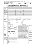
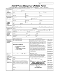
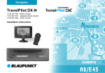
INSTALLATION INSTRUCTIONS
Arizona CM 148
Colorado CM 168
Florida RD 168
Nevada RDM 168
Alaska RDM 168
SAFTEY NOTES & GENERAL RECOMMENDATIONS
•
•
•
•
•
•
•
•
•
•
To avoid costly mistakes and serious damage, please carefully read all of the instructions
before you begin. You’ll be glad you did!
If you’re not confident that you can install the receiver correctly, have it installed by a qualified
Blaupunkt installation technician.
Use this receiver only with negative ground 12-Volt (11-16 Volt) direct current (DC).
A quick-acting 10A fuse protects this receiver. Do not substitute any other type of fuse.
During operation of the receiver, the receiver’s sidewall may heat up considerably. Be sure to
keep all wires away from hot parts of the housing.
Do not damage the vehicle’s battery, wiring or fuse box. Before drilling holes, look to see what
is on the other side!
Be sure to observe the safety notes of the vehicle manufacturer, such as those for airbags, alarm
systems, on-board computers, immobilisers, and braking systems, etc.
We recommend making and testing all electrical connections before installing the receiver.
Connect the leads (wires) according to instructions below.
Don’t assume that a seemingly-matching wire harness in the vehicle matches the receiver’s wire
harness wire-for-wire. Make sure before you connect anything!
Your Blaupunkt dealer may be able to sell you adapter harnesses for your vehicle, which can
make connections much easier.
Modification of this receiver or its mis-connection and/or mis-installation will void its warranty.
ELECTRICAL CONNECTION INSTRUCTIONS
A. Connect the Wire Harnesses to the Vehicle’s Electrical System (See Fig. 4)
To prevent short circuits or serious damage to the receiver and/or speakers:
1. Disconnect the vehicle battery’s negative terminal before making connections.
2. Connect the speakers and/or external amplifiers (if you have any) following the guidelines in the
SPEAKER & AMPLIFIER CONNECTION section on the next page.
3. Connect the blue (trigger output) lead to an antenna motor trigger switch input terminal (if you
have one). (Maximum amperage required must not exceed 150 mA.)
4. Florida RD 168, Nevada RDM 168, and Alaska RDM 168 only: Connect the orange ILLUMINATION lead to the vehicle’s adjustable illumination (dimmer).
5. Colorado CM 168, Nevada RDM 168, and Alaska RDM 168 only: If you have a cellular telephone
set that has a mute lead (lead that supplies constant ground when telephone is in use), connect
it to the dark green lead.
8 622 401 550
GB 1
6. Connect the black (power ground) lead to a grounded metal part on the vehicle. We recommend
grounding all audio system black ground leads (receiver, changer, additional amplifiers, etc.) to
a common grounding point, preferably a non-painted surface under the instrument panel.
red
+ switched
trigger output
10A
blue
black
orange
Fig. 4
yellow
dark green
power ground
illumination
constant power
tel.- mute
7. Connect the yellow (constant power) input lead to a source of constant battery power, preferably
directly to the battery. The wire must be 18-gauge or thicker.
8. After the other leads are connected, connect the red turn-on “IGNITION” lead using either of the
following alternatives:
A. (Recommended) – Connect it to a positive (+) 12 Volt power terminal that is energized only
when the ignition key is set to the “on” position or accessory position. (You can still turn the
unit on for one hour even if the ignition is off.)
B. This lead can instead be connected to a source of constant power, however, your receiver’s
operation will be completely separate from the ignition.
With either alternative, the receiver’s DSC Setting “DISP ON/OFF” allows you to choose whether
or not the receiver and its display are illuminated when the receiver is turned off, but still receiving
power via the red lead (i.e. ignition on).
9. Cover the ends of any unused leads with electrical tape. This will prevent them from touching the
vehicle or each other and causing a short circuit and damage to the receiver or vehicle.
10.Reconnect the vehicle’s battery.
11.Verify that no fuses have blown.
B. Test the Connections
1. To help prevent possible electrical damage from accidental misconnection of the receiver, first
attach your vehicle’s antenna. (With Florida RD 168, Nevada RDM 168 and Alaska RDM 168
only: if necessary, attach the antenna “elbow” connector and affixing bracket to the back of the
receiver.)
2. Be sure to detach the faceplate before you start to connect the receiver.
3. Plug the harness into the receiver.
4. Verify that the receiver’s and vehicle’s fuses haven’t blown.
5. Attach the faceplate and test the receiver.
6. Once the connections have been successfully made, you can begin the INSTALLATION. (See
below.)
GB 2
SPEAKER & AMPLIFIER CONNECTIONS
10A
The receiver’s Dual-Level Fader allows you to fade between the front and the rear channels using
the receiver’s internally-amplified output via front and/or rear speaker leads AND/OR its 4-channel
preamp output, providing tremendous flexibility in configuring your audio system arrangement:
• You can connect a speaker (regular, co-axial or tri-axial speakers or component speaker system,
all hereafter referred to simply as “speaker”) to each of the receivers’ four pairs of speaker leads.
• With the Blaupunkt preamp output adapter 7 607 893 093 (available separately), you can provide
4-channel preamp output to additional external amplifiers and power multiple speakers or
speaker systems through those amplifiers. (Blaupunkt amplifiers and speakers available
separately).
• You can use either or both of these two methods.
F
RR R
Fig. 6
R
LF L
+
+
+
+
-
LR
LF
RR
RF
Connecting Speakers to the Outputs from the Receiver’s Internal Amplifier
To prevent short circuits or serious damage to the receiver and/or speakers:
•
•
•
•
•
•
•
•
•
•
•
•
Disconnect the vehicle battery’s negative terminal before making connections.
Connect the speaker leads only as indicated on the speaker wire block. (See Fig. 6)
Only use speakers that have impedance ratings of 4 ohms or higher and have power-handling
capabilities greater than the receiver’s stated power level.
The receiver’s internal amplifier is designed to handle a 4-ohm load on each pair of speaker leads.
DON’T connect two speakers to a single pair of speaker leads (“in parallel”) unless both speakers
each have at least 8 ohms impedance.
DON’T connect the left and right speaker leads to each other or to the same speakers.
DON’T connect the front and rear speaker leads to each other or to the same speakers.
DON’T connect the negative speaker leads to each other.
DON’T connect the positive speaker leads to each other.
DON’T connect any active speakers (with built-in amplifiers) to the speaker leads unless their
owner’s manuals specifically state that this is O.K.
Cover the ends of any unused leads with electrical tape. This will prevent them from touching the
vehicle or each other and causing a short-circuit and damage to the receiver or vehicle.
Make the other electrical connections. (See previous page.)
GB 3
Connecting Additional Amplifiers or an Equalizer to the Receiver’s Preamp Output
Obtain the Blaupunkt RCA 4-channel preamp output adapter 7 607 893 093 from your dealer.
It includes a blue/white trigger lead for switching the amplifier on and off. Connect the adapter into
the top left section of the connector block on the back of the receiver. (See Fig. 7) Follow the
amplifier’s or equalizer’s instructions regarding connection. (Blaupunkt amplifiers available separately).
+12V
10A
+12V
Fig. 7
CD CHANGER OR AUX-IN CONNECTION
(Arizona, CM 148, Colorado CM 168, Nevada RDM 168, & Alaska RDM 168 Receivers)
10A
CD Changer Connection
These receivers can control a Blaupunkt CDC-A08 or CDC-A071 CD Changer (or with the adapter
harness 7 607 889 093, they can control a Blaupunkt CDC-A05 CD Changer)
(All available separately.) The changer cable plugs into the right top connector block on the back of
the receiver. (See Fig. 6) See the changer instructions for details.
3A
rt
+12V
Fig. 6
br
12V
Aux Input
If a changer is not connected, you can connect portable audio equipment to your receiver by
purchasing Blaupunkt accessory harness 7 607 897 093. It connects to the right top block on the rear
of the receiver. It includes a 2-meter aux-in cable with a 3.5 mm male plug for direct insert into your
portable equipment.
WIRELESS REMOTE CONTROL
(Colorado CM 168, Nevada RDM 168, & Alaska RDM 168 only)
This receiver’s most-frequently used features can be conveniently controlled from the steering
wheel with Blaupunkt’s unique Thummer III Steering-Wheel Remote Control. (Available separately.)
The Thummer III includes a receiving “eye” that can be placed virtually anywhere on the dash, which
connects into the center top block on the back of the receiver.
GB 4
INSTALLATION INSTUCTIONS
Recommendations
•
•
•
•
Carefully choose the mounting location so that the receiver won’t interfere with normal driving.
Avoid mounting locations where the receiver would be subject to high temperatures, such as from
direct sunlight or hot air from the heater, or where it would subject to dust, dirt or excessive
vibration.
The illustration below shows a typical installation, however, you may need to adjust the
installation, depending on the receiver. If you have questions or need additional installation
hardware, consult your Blaupunkt dealer.
Make sure the receiver is firmly anchored (preferably at both front and back) and does not vibrate.
Installing the Receiver in Most Dashboards
This car receiver and its mounting bracket are designed for installation in vehicles with a standard
DIN installation compartment measuring 182 x 53 mm, a 165 mm installation depth and an
instrument panel thickness of approximately 1 to 20 mm in the area of the tab fasteners.
(See Fig. 1)
1. Place the mounting bracket in the compartment and bend over all of the tabs possible.
(See Fig. 2)
2. Your vehicle may also allow you to provide extra stability at the back of the receiver. Look at the
wall behind the radio cavity to see if there is a small hole the size of the enclosed plastic plug,
If so, screw it onto the treaded bold at the back of the receiver before pushing it into the mounting
bracket.
3. With the detachable face off, place the receiver into the mounting bracket and push it in until the
side springs snap into position on the left and right. (You will hear an audible click.)
4. To remove the receiver, see the maintenance section on the next page.
8 601 310 742
182
165
53
1-20
Fig. 1
Fig. 2
GB 5
Installing the Receiver in a Japanese Car
This receiver is designed for easy installation in most popular Japanese cars that have “ISO” (sidebracket) mounting system. If you have questions, ask your Blaupunkt dealer.
1. Remove the vehicle’s “bezel” trim piece and the remove the existing radio.
2. Unscrew the bolts on each side of the receiver to remove the trim ring. Save the trim ring in case
you ever want to install the receiver in another vehicle.
3. Use the vehicle’s own mounting hardware to attach the unit.
4. With the detachable face removed, reinstall the vehicle’s bezel.
5. Only after the bezel in reinstalled, attach the face.
max. M5x8
NISSAN
TOYOTA
max. M5x8
max.
max. M5x8
M5x8
MAINTENANCE
Removing the Receiver
Insert the “release handles” into the holes in the panel on the left and right of the receiver and push
them in until you hear a distinct snap, which indicates the side springs are unlocked. Pull the unit
out using both handles. (See Fig. 3) Note: Handles that have snapped into place can only be
removed after you have pulled the receiver out of the complement. Remember where you store the
“release handles”.
8 601 910 002
1
2
1
2
Fig. 3
Fuse Replacement
When replacing the fuse, be sure to use one with the correct amperage, which will be stated on the
fuse case. Never use a fuse that has a stated amperage exceeding the one supplied for this
receiver as this could cause malfunction and serious damage to the receiver.
GB 6
Cleaning the Connectors
The receiver may not operate properly if the connectors between the receiver and the detachable
face are contaminated with dirt. To clean the connectors, use a cotton swab and isopropyl alcohol
(90% or higher). Be sure to clean them with a vertical motion. Never clean them horizontally,
because this could damage the contact points.
Affixing the Detachable Face for Retail Display
The detachable face can be affixed to the receiver’s chassis, which is desirable for a retail display.
To affix the face, obtain the small self-tapping screw from the hardware pack and drive it into the
upper hole at the front left side of the chassis using a Phillips screwdriver. The bolt will self-thread
the hole. (See Fig. 8)
Fig. 8
Faceplate affixing screw goes here
TROUBLESHOOTING – Refer to the receiver’s Owner’s Manual. If you have questions, please
consult your Blaupunkt dealer or in the United States call 1-800-266-2528.
Installer – These Installation Instructions are the property of the consumer!
Make sure they are left in the vehicle!
8 622 401 550
GB 7