1
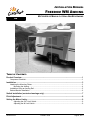
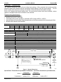
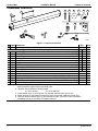
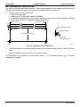
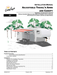
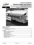
INSTALLATION MANUAL FREEDOM WM AWNING RV MOTORIZED OR MANUAL LATERAL ARM BOX AWNING TABLE OF CONTENTS Product Overview .......................................................................................................................... 1 Component Checklist.............................................................................................................................. 1 Installation ..................................................................................................................................... 3 Attaching the Mounting Plates ................................................................................................................ 3 Mounting the Awning ...................................................................................................................... 4 Installation Using an Awning Rail ........................................................................................................... 5 Bottom Bracket Installation ..................................................................................................................... 6 Switch Installation (motorized awnings only) ............................................................................. 7 Pitch Adjustment ........................................................................................................................... 8 Setting the Motor Limits ............................................................................................................... 9 Adjusting the OUT Limit Switch ...................................................................................................... 9 Adjusting the IN Limit Switch .......................................................................................................... 9 052563-001r9 Printed in USA August, 2013 PROPRIETARY STATEMENT The Freedom Awning is a product of Carefree of Colorado, located in Broomfield, Colorado, USA. The information contained in or disclosed in this document is considered proprietary to Carefree of Colorado. Every effort has been made to ensure that the information presented in the document is accurate and complete. However, Carefree of Colorado assumes no liability for errors or for any damages that result from the use of this document. The information contained in this manual pertains to the current configuration of the models listed on the title page. Earlier model configurations may differ from the information given. Carefree of Colorado reserves the right to cancel, change, alter or add any parts and assemblies, described in this manual, without prior notice. Carefree of Colorado agrees to allow the reproduction of this document for use with Carefree of Colorado products only. Any other reproduction or translation of this document in whole or part is strictly prohibited without prior written approval from Carefree of Colorado. SAFETY INFORMATION WARNING A WARNING INDICATES A POTENTIALLY HAZARDOUS SITUATION WHICH, IF NOT AVOIDED, COULD RESULT IN DEATH OR SERIOUS INJURY AND/OR MAJOR PROPERTY DAMAGE. CAUTION A CAUTION INDICATES A POTENTIALLY HAZARDOUS SITUATION THAT MAY CAUSE MINOR TO MODERATE PERSONAL INJURY AND/OR PROPERTY DAMAGE. IT MAY ALSO BE USED TO ALERT AGAINST UNSAFE PRACTICES. NOTE: A note indicates further information about a product, part, or step. Tip: A tip provides helpful suggestions. Safety Notes: Always disconnect battery or power source before working on or around the electrical system. Always wear appropriate safety equipment (i.e. goggles). Always use appropriate lifting devices and/or helpers when lifting or holding heavy objects. When using fasteners, use care to not over tighten. Soft materials such as fiberglass and aluminum can be "stripped out" and lose the ability to grip and hold. Reference Publications located @ www.carefreeofcolorado.com:' 052563-001 Installation Manual 052563-201 Owner's Manual 052563-301 Service Manual Carefree of Colorado 2145 W. 6th Avenue Broomfield, CO 80020 a Scott Fetzer company Installation Manual Carefree FREEDOM WM PRODUCT OVERVIEW The Freedom Awnings are state of the art lateral arm awnings. When retracted, the housing provides protection against the elements while the streamlined styling blends in with the coach sidewall. The full tension canopy fabric allows the awning to be partially or fully extended for best shade coverage. Each unit is equipped with lateral support arms. No vertical arms interfere with coach sidewalls, custom graphics or equipment that may be mounted on the sidewalls. Freedom Awning Specifications: Fully retractable and self-storing; Available as manual or motorized; The sealed awning motor operates on standard 12VDC (range 10VDC to 14VDC); Case and frame are constructed of high-strength aluminum extrusions protected with a polyester paint finish; Stainless steel fasteners and hardware. SPECIFICATIONS centimeters inches Widths: 200 79 Extension: 220 87 152cm (60") 244 96 180cm (72") 257 101 200cm (80") 300 118 350 138 400 157 250cm (98") 450 177 500 197 LEADING EDGE POSITION ACTUATION AND CONTROL Lateral Arm Spring Motorized: Manual: Power: Position Control: Open Minimum Tension Roll Out/In Controlled by Electrical Motor Roll Out/In Controlled by Manual Crank MOTOR SPECIFICATIONS Tubular 12VDC Minimum: 10VDC Output: 30 Watts Nominal Current: 2.5Amps Max Current: 14Amps (stall @ min voltage) Motor and controls are routed and hardwired into the vehicle’s 12V system Continuous: 6Nm/4.5 ft-lbs. Tightening: 18Nm/13.2 ft-lbs. 24 rpm Motor Type: Power: Power Source: Torque Speed COLORS AVAILABLE Satin, White or Black Vinyl Case Fabric:1 Awning Width 3.8" [9.7cm] 4.25" 5.8" [14.8cm] 2.25" Fabric Width [10.8cm] [5.7cm] 6.5" [16.5cm] Support Legs Stored Inside Lead Rail See Text for Door Clearance Hieghts 30"-38" (optimum) 50" (maximum) Wall Mount Bottom Bracket for Support Legs 1 3/8" x 2 1/8" Pivot Pivot wm001 Figure 1. General Dimensions. Special Note: Dimensions are provided in centimeters. Conversion formulas are provided below; 052563-001r9 Inches = Centimeters 2.54 Centimeters = Inches x 2.54 = Millimeters 25.4 Millimeters = Inches x 25.4 1 FREEDOM WM Installation Manual Carefree of Colorado COMPONENT CHECKLIST 4 3 5 6 7 8 9 2 1 10 11 12 RV PATIO O WNER 'S M FREE ANUA L , WINDOW DOM A WNI NGS AND O TD AWNIN GS Freed om Patio Awnin g Freed om Windo w and OtD Awnin gs Specia operatil Note: This Manufang controls manua configu cturers providel provide s a d include ration (OEM's basic ) may by Carefre of descrip compond, contactthe switche alter e of tion ents or the are not coach s. If yourc hange Colorad of the 0525 produc o. 49- 2 covered manufa control the placem 01 Some t and by the cturer s Origina the standar ent, Carefre for an do not style l e warranaccura match and/or Equipm d the te descrip ent ty. style Print function ed in or descrip al tion. USA OEM tion furnish ed Oc t o ber, 2007 15 14 16 13 WM003 Figure 2. Component Checklist. ITEM DESCRIPTION QTY NOTE 1 Awning Assembly 1 1 HARDWARE KITS (application depending on Awning Length, see note 2) 2 A B 2 Mounting Plate 12cm [4 3/4"] 3 2 3 Mounting Plate 40 cm [15.75"] 2 4 Screw, Lag #14 x 1 1/2" 3 3 5 Carriage Screw M6-1 x 50mm 6 12 6 Fender Washer 6 12 7 Nut, Nylock M6 6 12 8 Bolt Cover 6 12 9 Screw, Square Drive Pan Head #6 x 3/8" 6 8 10 Bottom Bracket 2 11 Screw, Flat Head #10 x 3/4" 4 12 Owner's Manual 1 5 13 Clip, Crank Handle Used with Manual Crank Only 2 3 14 Crank Handle, "Hook" Used with Manual Crank Only 1 3 15 Switch Kit Used with Motorized Only 1 4 16 Override Key 3/8" 1 5 Notes: 1. Awning configuration is specified at time of order, including awning length, fabric, color etc. Check awning assembly against original purchase order. 2. Hardware Kits are based on awning length: A = 4m or shorter B = 4.5m and 5.0m 3. Crank Handle (item 13) and clip (item 14) used with manual crank version only. 4. Switch kit (Item 15) and manual override key (item 16 used with motorized version only 5. Place the Owner's Manual (item 12) and override key (item 16) with RV owner information. Installation manual, if included is for installer reference. 2 052563-001r9 Installation Manual Carefree FREEDOM WM INSTALLATION Two standard methods are available to mount the Freedom awning. The awning may be mounted using a set of mounting plates that attaches to the vehicle wall (refer to page 3) If using adaptor brackets, follow the instructions included with bracket kit then proceed with "Mounting the Awning" on page 4. The awning may also be mounted using an existing awning rail. Prior to mounting the awning: Review both mounting methods to determine the best mounting method for the particular application. The mounting brackets require access to the inside of the mounting surface. If there is an awning rail installed, check that the awning rail runs the full length of the awning. The awning rail must be extremely straight to accommodate the awning mount. The rail must be attached to structural components for stability. Ensure that the awning will not interfere with light fixtures, exhaust vents, openings, etc. ATTACHING THE MOUNTING PLATES 1. Determine the optimum positioning of the awning. 1.1. The centerline of the awning fabric is offset from the centerline of the awning assembly. To align the center of the fabric, use the backplate of the awning assembly for measurements. 1.2. The bottom of the mounting plates should be 28cm [11"] above any openings or frames to avoid interference when the awning is installed. NOTE: Height is based on clearance over a 76cm [30"] door extension. The mounting height will vary 1.9cm [.75"] for every 5cm [2"] change in extension. For longer extensions, add the calculated difference. For shorter extensions, subtract the difference. Dimensions are based on the lowest pitch with no lift from the vertical support legs. 1.3. Measure each end of the awning position from the ground so that the mounted awning is parallel to the ground. 2. Mark the position with a chalk line. 3. Determine the correct plate pattern then use the plates as a template and drill 8mm [5/16"] holes through the vehicle wall to match the plates. 4.0m or less Edge of Back Plate Center of Back Plate "A" "A" 12cm 12cm 12cm 3.5" [9cm] 1.75" [4.5cm] Awning Length Edge of Back Plate "A" 2.0m 1.0" [2.5cm] 2.2m 4.25" [11cm] 2.44m 2.75" [7cm] 2.57m 1.0" [2.5cm] 3.0m 1.0" [2.5cm] 3.5m 10.75" [27.5cm] 4.0m 20.25" [51.5cm] Awning Edge of Back Plate Edge of Back Plate 58.25" [148cm] 1/2" [1.25cm] 4.5m 58.25" [148cm] 1/2" [1.25cm] 68" [173cm] 5.5" [14cm] 5.0m 68" [173cm] 5.5" [14cm] 40cm 12cm 12cm 3.5" [9cm] 40cm 1.75" [4.5cm] Awning Length WM002 Figure 3. Mounting Plate Pattern. 052563-001r9 3 FREEDOM WM Installation Manual Carefree of Colorado Edge of Case Awning CAUTION For proper operation of 2.0m the awning, the brackets must be placed under the arm knuckles. If it is necessary to position the brackets differently than shown in Figure 3, use the knuckle positions shown. 3.25" 8 cm 2.2m 6.75" 17 cm 2.44m 5.0" 13 cm 2.57m 3.25" 8 cm 3.0m 3.25" 8 cm 3.5m 13.25" 33.5 cm 4.0m 22.5" 57.5 cm 4.5m 4.5" 11.5 cm 5.0m 14.5" 37 cm Arm Knuckle Center Arm Knuckle Center Knuckle 4.5m & 5m 4.5m 5.0m 60.5" 70.5" 153.5 cm 179 cm Typical Both Sides WM045 M6-1 x 50mm Carriage Bolt 8mm [5/16”] Hole 4. Attach the plates using the supplied M6-1 x 50mm carriage bolts, fender washers, nuts and bolt covers. Bolt Cover Nylock Nut Fender Washer Mounting Plate WM004 Figure 4. Typical Plate Attach. 5. For motorized awnings only: 5.1. The motor wire comes out of the back of the motor end cap. Use the dimensions shown to locate the hole into the vehicle. 5.2. The hole location can be located in the areas shown to avoid interior framing, cabinets and electrical components that could be damaged or interfere with the hole location. Edge of Back Plate 5.3. Ensure that the motor wires are accessible after routing. 3/16" [5mm] (min.) There is 70" [180cm] of wire furnished with the motor. If the final routing to the switch location is greater than the supplied wire from the motor, the installer must splice additional 18awg wire to the motor wires. Wire 5/16" [8mm] and splices are furnished by the installer. 5/8" [16mm] Hole thru Wall 5.4. Drill an 5/16" [8mm] hole through the outer vehicle wall. Locate hole in these areas WM007 This is a preliminary step, the wire and switch installation are completed after the awning is secured. Figure 5. Motor Wire Routing. Mounting the Awning 1. Set the awning into the hooks of the mounting plates. For motorized awnings: Route the motor wires through the hole drilled previously while lifting the awning into position. Back Plate Route Motor Cable through Groove in Back Case Tip: If the wire is routed along the back of the case, use small pieces of tape to hold the wire in place while lifting the awning. 2. Adjust the position of the awning horizontally as required. 3. Attach the awning case to the mounting plates using two (2) self-tapping #6 x 3/8" screws for each bracket. 4 Mounting Plate #6 x 3/8” Screw (2 per Bracket) WM005 052563-001r9 Installation Manual Carefree FREEDOM WM INSTALLATION USING AN AWNING RAIL The awning may be mounted using an existing awning rail. Awning rails are not furnished with the awning. 1. Determine the optimum positioning of the awning. 6. When installed, the bottom of the awning case is 13.3cm [5 1/4”] from the centerline of the awning rail. The rail must be mounted a minimum of 41.3cm [16.25”] above openings to avoid interference. NOTE: Height dimension is based on clearance over a 76cm [30"] door extension. The mounting height will vary 1.9cm [.75"] for every 5cm [2"] change in extension. For longer extensions, add the calculated difference. For shorter extensions, subtract the difference. 7. The centerline of the awning fabric is offset from the centerline of the awning assembly. To align the center of the fabric, use the backplate of the awning assembly for measurements. 7.1. Lightly spray the inside track of the awning rail with a silicone lubricant. 7.2. Using a minimum of two people, lift the awning Mounting Rail up and tilt as shown. 7.3. Hook the mounting rail into the awning rail and roll down. Awning Rail 7.4. Adjust the position of the awning horizontally as required. It may be necessary to lift the awning so that it will slide in the awning rail. WM006 Figure 6. Mount Using Awning Rail. 7.5. For the motorized awning only: Lift the awning upward slightly. On the coach wall, mark the location of where the motor wires exit the awning case. Measure and drill one 8mm hole through the outer wall at the mark. NOTES: Adjust the location as required. Measure to avoid any interior framing, cabinets, electrical components etc. that could be damaged or interfere with the hole location. Ensure that the motor cables are accessible after routing in the next step. This is a preliminary step, the wire and switch installation are completed after the awning is secured. Route the motor wires through the hole and seal with silicone sealant. 10. Rotate the awning down. 11. Open the awning 14"-18" [35 - 45cm] to allow access to the back plate. NOTE: To open the motorized awning, momentarily connect the motor wires to a 9-14VDC drill battery or car battery. If the motor runs in the reverse direction, reverse the leads. 12. Drill three (3) 3/16" [4.8mm] holes through the back of the case into the mounting surface and into the structure. Use care to not drill through the inner wall. 13. In the awning case, ream out the 3/16" [4.8mm] holes to 5/16" [8mm]. Do not allow the drill to extend into the wall. Drill Area Arm Mount Drill Area Drill Area Center Between Arms Arm Mount WM008 Figure 7. Securing the Awning Case. CAUTION THE SCREWS MUST BE LOCATED IN THE OPEN AREAS OF THE AWNING CASE AS SHOWN. THE ARMS CANNOT CLOSE COMPLETELY IF THE SCREW HEADS ARE UNDERNEATH. 14. Secure the awning using three (3) #14 x 1 1/2" lag screws. 052563-001r9 5 FREEDOM WM Installation Manual Carefree of Colorado BOTTOM BRACKET INSTALLATION The awning is equipped with vertical supports. These supports extend from the leading edge of the awning to a bracket mounted on the wall or may be used in a carport position on the ground. 1. Determine the location of the brackets: Close the awning if open. Measure out .5" [1.2cm] from the edge of the lead rail. At the marks made previously, measure down vertically and mark the location of the brackets. The ideal location is 37"-50" [94-127 cm] below the bottom of the awning. Edge of Lead Rail Edge of Lead Rail 1/2" [1.2cm] 5/32" [4mm] Pilot Hole 1/2" [1.2cm] Bottom Bracket 37"-50" [94-127 cm] #10 x 3/4" Flat Head Screws Pivot Pivot WM009 Figure 8. Wall Mounted Support Brackets. 2. Center the brackets on the location marks and using the bracket as a template, drill two (2) 4mm [5/32"] pilot holes. 3. Attach the brackets with two (2) #10 x 3/4": flat head screws. This completes the installation of the manual awning. Installation" on page 7. 6 For motorized awnings go to "Switch 052563-001r9 Installation Manual Carefree FREEDOM WM SWITCH INSTALLATION (MOTORIZED AWNINGS ONLY) CAUTION ALWAYS DISCONNECT THE BATTERY AND ELECTRICAL SOURCES BEFORE WORKING WITH THE ELECTRICAL WIRING. 1. Determine the location for the switch. There is approximately 180cm [70"] of wire from the awning motor. If the distance to the switch exceeds the furnished wire, the installer must furnish 18 awg wire and butt splice to the motor wires. Location should provide the operator a view of the awning during operation. The switch requires a 4.8cm x 7.3cm [1 7/8" x 2 7/8"] area on the mounting surface and a minimum clearance depth of 3.2cm [1.25"] from the mounting surface. 1. At the switch location, cut a rectangular hole 1.25”(3.2cm) x 1.88” (4.8cm) through the mounting surface. 1.25 [ 3 . 2 c m” ] #6 x 3/4 Screw (2 plcs) 1.88 2.88 [ 7 . 3 c m” (ref) ] 1.88” [4.8 (ref) cm] [ 4 . 8 c m” ] 1.25” [3.2cm] Min. Clearance From Mounting Face to Rear of Switch Connector SK002d Figure 9. Switch Installation. Left Side Orientaion SK002a 2. Determine the switch orientation: 2.1. The wires of the connector extend from the side of the switch with 3 terminals on the back. 2.2. For wire routing on the right side of the switch as shown in Details A and B, orient the switch with the 3 terminals on the right. 2.3. For wire routing on the left side of the switch as shown in Detail C, orient the switch with the 3 terminals on the left. 2.4. Push the switch into the faceplate until the tabs on the switch “click” into place behind the faceplate. Ensure that the switch and faceplate are oriented so that the lettering is up and the wires are oriented as desired. 2.5. Set switch aside. 3. Route the awning motor wires through the switch hole and attach to the switch connector: To +12VDC BLACK RED BLUE Motor Wire BROWN Motor Wire BLUE WHITE WHITE BLUE RED→ WHITE→ BLUE→ BLACK→ 052563-001r9 BROWN Motor Wire RED BLACK CONNECTOR WIRE COLOR To Ground BLUE Motor Wire To +12VDC To Ground SK003a LH CONNECTOR ORIENTATION +12VDC BLUE BROWN Ground (motor wire) (motor wire) SK003b RH CONNECTOR ORIENTATION +12VDC BROWN BLUE Ground (motor wire) (motor wire) 7 FREEDOM WM Installation Manual Carefree of Colorado 5. Run a minimum 14 awg wire from the power distribution panel (auxiliary battery circuit) or equivalent. The circuit should be protected by a 15-amp fuse. 6. Run a minimum 14 awg wire to system ground. NOTE: If the wire run is 30 feet or longer, use 12awg wire to prevent voltage drop. 4. Route the two wires through the mounting hole. Butt splice the 12VDC wire to the RED connector wire. Butt splice the ground wire to the BLACK connector wire. 5. Attach the connector to the switch. 6. Restore power and test the switch operation. 7. If the awning operates opposite to the switch plate markings: Shut off power; Reverse motor wires connected to the blue and white connector wires; Restore power and test. 8. Push the wires, connector and switch into the mounting hole and secure the switch plate. Use two (2) #6 x 3/4" flat head screws. PITCH ADJUSTMENT The Freedom WM provides minor pitch adjustment for aligning the lead rail with the case. This adjustment is only for fine-tuning the installation. It is not intended as an operational pitch adjustment. CAUTION WHEN THE PITCH OF THE AWNING IS ADJUSTED, IT IS IMPORTANT THAT THE LEAD RAIL IS PARALLEL TO THE AWNING HOUSING. 1. Open the awning to access the adjustment screw located on the arm case knuckle. 2. Have a second person lift up on the lead rail to relieve the pressure on the adjustment screw. Lower Raise 3. Using a 5mm allen wrench, turn the adjustment screw Arm Case Knuckle Pitch Adjustment Screw WM013 clockwise to raise the lead rail; turn the adjustment screw counterclockwise to lower the lead rail. Figure 10. Pitch Adjustment. 4. Repeat for the other side as necessary. MANUAL OVERRIDE (MOTORIZED VERSIONS ONLY) If power to the vehicle is not available, the awning can be safely retracted using the manual override located on the idler (right) end of the case. NOTE: This procedure cannot be used to extend the awning. Remove Plug 3/8” Socket Drive Extension 1. Remove the plug from the right endcap and save. 2. Insert a 3/8" socket drive extension and handle into the square drive hole inside the end cap. 3. Turn the handle counterclockwise until the awning is retracted. 4. Replace the plug. WM012a CAUTION After closing the awning with the manual override, the lead rail may move out from the case 1/4" 1/2". This is normal and the awning is secure for travel until power is restored or repairs are completed. Do not attempt to force the lead rail in with the override, serious damage can occur to the awning. 8 052563-001r9 Installation Manual Carefree FREEDOM WM SETTING THE MOTOR LIMITS The motor limit switches are preset at the factory for best operation of the awning. It may be necessary to reset the switches. The “OUT” limit switch is used to stop the motor when the awning is fully extended. The “IN” limit switch is used to stop the motor when the awning is fully retracted. The limit switches are located inside the motor endcap. “OUT” 4mm Hex “IN” Endcap 4mm Hex Plug WM011a Figure 11. Motor Limit Switches. To access the switches, remove the outer motor endcap and plug. Adjusting the OUT Limit Switch 1. 2. 3. 4. 5. Extend the awning out completely. Confirm that the arms are fully extended. The motor should stop and the fabric should be tight. If the motor continues to run, the fabric will sag; or, if the motor quits before the arms are extended, it will be necessary to adjust the “OUT” limit switch. Using a 4mm Allen wrench turn the “OUT” limit switch. CLOCKWISE increases time the motor runs during extension, COUNTERCLOCKWISE reduces the time the motor runs. NOTE: It is best to make the adjustments in increments of a single turn. 3 full turns of the screw equals approximately 2” of fabric extension. Extend and retract the awning several times to confirm that the adjustment is correct. Repeat steps 3 and 4 as required until the awning extends correctly. Adjusting the IN Limit Switch 1. Retract the awning in completely. 2. Confirm that the arms are fully retracted. The motor should stop when the awning is fully retracted. If the motor quits before the arms are fully retracted, it will be necessary to adjust the “IN” limit switch. 3. Using a 4mm Allen wrench turn the “IN” limit switch. Clockwise increase time the motor runs during retraction, counter clockwise reduces the time the motor runs. NOTE: It is best to make the adjustments in increments of a single turn. 3 full turns of the screw equals approximately 2” of fabric extension. 4. Extend and retract the awning several times to confirm that the adjustment is correct. 5. Repeat steps 3 and 4 as required until the awning retracts correctly. 052563-001r9 9


![User's Manual AH-480 Series [Machine / Software]](http://vs1.manualzilla.com/store/data/006867875_1-b2cd01726e15f409a063f19433f9385d-150x150.png)