1
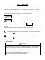
HITACHI PROGRAMMABLE CONTROLLER
RESISTANCE TEMPERATURE DETECTIVE
INPUT MODULE(EH-PT4)
APPLICATION MANUAL
NJI-324(X)
WARNING
To ensure that the equipment described by this manual. As well as all equipment connected
to and used with it, operate satisfactorily and safety, all applicable local and national codes
that apply to installing and operating the equipment must be followed. Since codes can vary
geographically and can change with time, it is the user’s responsibility to determine which
standard and codes apply, and to comply with them.
FAILURE TO COMPLY WITH APPLICABLE CODES AND STANDARDS CAN RESULT IN
DAMAGE TO EQUIPMENT AND/OR SERIOUS INJURY TO PERSONNEL.
INSTALL EMARGENCY POWER STOP SWITCH, WHICH OPERATES INDEPENDENTLY OF
THE PROGRAMMABLE CONTROLLER TO PROTECT THE EQUIPMENT AND/OR
PERSONNEL IN CASE OF THE CONTROLLER MALFUNCTION.
Personnel who are to install and operate the equipment should carefully study this manual
and any other referred to by it prior to installation and/or operation of the equipment. Hitachi
Industrial Equipment Systems Co., Ltd. constantly strives to improve its products, and the
equipment and the manual(s) that describe it may be different from those already in your
possession.
If you have any questions regarding the installation and operation of the equipment, or if
more information is desired, contact your local Authorized Distributor or Hitachi Industrial
Equipment Systems Co., Ltd.
IMPORTANT
THIS EQUIPMENT GENERATES, USES, AND CAN RADIATE RADIO FREQUENCY
ENERGY AND, IF NOT INSTALLED AND USED IN ACCORDANCE WITH THE
INSTRUCTION MANUAL, MAY CAUSE INTERFERENCE TO RADIO COMMUNICATIONS.
AS TEMPORARILY PERMITTED BY REGULATION, IT HAS NOT BEEN TESTED FOR
COMPLIANCE WITH THE LIMITS FOR CLASS A COMPUTING DEVICES PURSUANT TO
SUBPART J OF PART 15 OF FCC ROULES, WHICH ARE DESIGNED TO PROVIDE
PEASONABLE PROTECTION AGAINST SUCH INTERFERENCE.
OPERATION OF THIS EQUIPMENT IN A RESIDENTIAL AREA IS LIKELY TO CAUSE
INTERFERENCE IN WHICH CASE THE USER, AT HIS OWN EXPENSE, WILL BE
REQUIRED TO TAKE WHATEVER MEASURES MAY BE REQUIRED TO CORRECT THE
INTERFERENCE.
LIMITED WARRANTY AND IMITATION OF LIABILITY
Hitachi Industrial Equipment Systems Co., Ltd. (Hitachi) warrants to the original purchaser
that the programmable logic controller (PLC) manufactured by Hitachi is free from defects in
material and workmanship under normal use and service. The obligation of Hitachi under this
warranty shall be limited to the repair or exchange of any part or parts which may prove
defective under normal use and service within eighteen (18) months from the date of
manufacture or twelve (12) months from the date of installation by the original purchaser
which ever occurs first, such defect to be disclosed to the satisfaction of Hitachi after
examination by Hitachi of the allegedly defective part or parts. This warranty in expressly in
lieu of all other warranties expressed or implied including the warranties of merchantability
and fitness for use and of all other obligations or liabilities and Hitachi neither assumes, nor
authorizes any other person to assume for Hitachi, any other liability in connection with the
sale of this PLC. This warranty shall not apply to this PLC or any part hereof which has been
subject to accident, negligence, alternation, abuse, or misuse. Hitachi makes no warranty
whatsoever in respect to accessories or parts not supplied by Hitachi. The term “original
purchaser”, as used in this warranty, shall be deemed to mean that person for whom the
PLC in originally installed.
In no event, whether as a result of breach of contract, warranty, tort (including negligence) or
otherwise, shall Hitachi or its suppliers be liable for any special, consequential, incidental or
penal damages including but not limited to, loss or profit or revenues, loss of use of the
products or any associated equipment, damage to associated equipment, cost of capital,
cost of substitute products, facilities, services or replacement power, down time costs, or
claims of original purchaser’s customers for such damages.
To obtain warranty service, return the product to your distributor, or send it with a description
of the problem, proof of purchase, post paid, insured, and in a suitable package to:
Quality Assurance Dept.
Hitachi Industrial Equipment Systems Co., Ltd.
46-1 Ooaza-Tomioka Nakajo-machi
Kitakanbara-gun, Niigata-ken
959-2608 JAPAN
Copyright 2002 by Hitachi Industrial Equipment Systems Co., Ltd.
All Right Reserved – Printed in Japan
The Information and/or drawing set forth in this document and all right in and to
inventions disclosed herein and patent which might be granted thereon disclosing or
employing and the materials, methods, techniques or apparatus described herein
are the exclusive property of Hitachi Industrial Equipment Systems Co., Ltd .
No copies of the information or drawings shall be made without the prior constant of
Hitachi Industrial Equipment Systems Co., Ltd.
Hitachi Industrial Equipment Systems Co., Ltd. provides customer assistance in
varied technical areas. Since Hitachi does not possess full access to data
concerning all of the uses and applications of customer’s products, responsibility is
assumed by Hitachi neither for customer product design nor for any infringement of
patents or rights of others, which may result from Hitachi assistance.
The specifications and descriptions contained in this manual were accurate at the
time they were approved for printing. Since Hitachi Industrial Equipment Systems
Co., Ltd. Incorporated constantly strives to improve all its products, we reserve the
right to make changes to equipment and/or manual at any time without notice and
without incurring any obligation other than as noted in this manual.
Hitachi Industrial Equipment Systems Co., Ltd. assumes no responsibility for errors
that may appear in this manual.
As the product works with user program, and Hitachi Industrial Equipment Systems
Co., Ltd. cannot test all combination of user program components, it is assumed
that a bug or bugs may happen unintentionally. If it is happened: please inform the
fact to Hitachi Industrial Equipment Systems Co., Ltd. or its representative. Hitachi
will try to find the reason as much as possible and inform the countermeasure when
obtained.
Nevertheless Hitachi Industrial Equipment Systems Co., Ltd. intends to make
products with enough reliability, the product has possibility to be damaged at any
time. Therefore personnel who are to install and operate the equipment have to
prepare with the countermeasure such as power off switch can be operated
independently of the controller. Otherwise, it can result in damage to equipment
and/or serious injury to personnel.
Safety Precautions
Read this manual and related documents thoroughly before installing, operating, performing
preventive maintenance or performing inspection, and be sure to use the unit correctly.
Use this
product after acquiring adequate knowledge of the unit, all safety information, and all cautionary
information.
Also, make sure this manual enters the possession of the chief person in charge of
safety maintenance.
Safety caution items are classified as "Danger" and "Caution" in this document.
DANGER
: Cases where if handled incorrectly a dangerous circumstance may be created, resulting in
possible death or severe injury.
CAUTION
: Cases where if handled incorrectly a dangerous circumstance may be created, resulting
in possible minor to medium injury to the body, or only mechanical damage.
However, depending on the circumstances, items marked with
CAUTION
may result in
major
accidents.
In any case, they both contain important information, so please follow them closely.
Icons for prohibited items and required items are shown below:
: Indicates prohibited items (items that may not be performed). For example, when open flames
are prohibited,
is shown.
: Indicates required items (items that must be performed). For example, when grounding must
be performed,
is shown.
1. About installation
CAUTION
l
Use this product in an environment as described in the catalogue and this document.
If this product is used in an environment subject to high temperature, high humidity, excessive
dust, corrosive gases, vibration or shock, it may result in electric shock, fire or malfunction.
l
Perform installation according to this manual.
If installation is not performed adequately, it may result in dropping, malfunction or an
operational error in the unit.
l
Do not allow foreign objects such as wire chips to enter the unit.
They may become the cause of fire, malfunction or failure.
2. About wiring
REQUIRED
l
Always perform grounding (FE terminal).
If grounding is not performed, there is a risk of electric shocks and malfunctions.
CAUTION
l
Connect power supply that meets rating.
If a power supply that does not meet rating is connected, fire may be caused.
l
The wiring operation should be performed by a qualified personnel.
If wiring is performed incorrectly, it may result in fire, damage, or electric shock.
3. Precautions when using the unit
DANGER
l
Do not touch the terminals while the power is on.
There is risk of electric shock.
l
Structure the emergency stop circuit, interlock circuit, etc. outside the programmable controller
(hereinafter referred to as PC).
Damage to the equipment or accidents may occur due to failure of the PC.
However, do not interlock the unit to external load via relay drive power supply of the relay
output module.
CAUTION
l
When performing program change, forced output, RUN, STOP, etc., while the unit is running,
be sure to verify safety.
Damage to the equipment or accidents may occur due to operation error.
l
Supply power according to the power-up order.
Damage to the equipment or accidents may occur due to malfunctions.
4. About preventive maintenance
DANGER
l
Do not connect the ,
of the battery in reverse. Also, do not charge, disassemble, heat,
place in fire, or short circuit the battery.
There is a risk of explosion or fire.
PROHIBITED
l
Do not disassemble or modify the unit.
These actions may result in fire or malfunction.
CAUTION
l
Turn off the power supply before removing or attaching module/unit.
Electric shock, malfunction or failure may result.
Revision
No.
Content
Date
Manual No.
Table of contents
1. Introduction
1-1 to 1-4
1.1 Before Use ・・・・・・・・・・・・・・・・・・・・・・・・・・・・・・・・・・・・・・・・・・・・・・・・・・・・・・・・・・・・・・ 1-2
1.2 Precaution on Use ・・・・・・・・・・・・・・・・・・・・・・・・・・・・・・・・・・・・・・・・・・・・・・・・・・・・・・・ 1-3
1.3 Features ・・・・・・・・・・・・・・・・・・・・・・・・・・・・・・・・・・・・・・・・・・・・・・・・・・・・・・・・・・・・・・・・ 1-3
1.4 Principle of Operation ・・・・・・・・・・・・・・・・・・・・・・・・・・・・・・・・・・・・・・・・・・・・・・・・・・・ 1-4
2. Structure and Nameplate
2-1
2.1 Structure and Name of Each Part ・・・・・・・・・・・・・・・・・・・・・・・・・・・・・・・・・・・・・・・・・・ 2-1
3. Specification
3-1 to 3-2
3.1 Specification list ・・・・・・・・・・・・・・・・・・・・・・・・・・・・・・・・・・・・・・・・・・・・・・・・・・・・・・・・ 3-1
3.2 Terminal layout and internal circuit ・・・・・・・・・・・・・・・・・・・・・・・・・・・・・・・・・・・・・・・ 3-2
4. Block Diagram
4-1
4.1 Internal Block Diagram ・・・・・・・・・・・・・・・・・・・・・・・・・・・・・・・・・・・・・・・・・・・・・・・・・・ 4-1
5. External Wiring
5-1
5.1 Resistance Temperature Detective Connection Method and External Wiring
・・・・・・・・・・・・・・・・・・・・・・・・・・・・・・・・・・・・・・・・・・・・・・・・・・・・・・・・・・・・・・・・・・・・・・・・・ 5-1
6. Setting
6-1
6.1
Setting of Temperature Range ・・・・・・・・・・・・・・・・・・・・・・・・・・・・・・・・・・・・・・・・・・・ 6-1
7. Collection of Temperature Data
7-1 to 7-7
7.1 I/O Allocation ・・・・・・・・・・・・・・・・・・・・・・・・・・・・・・・・・・・・・・・・・・・・・・・・・・・・・・・・・・ 7-1
7.2 Temperature Data ・・・・・・・・・・・・・・・・・・・・・・・・・・・・・・・・・・・・・・・・・・・・・・・・・・・・・・ 7-2
7.3 Example of Calculation ・・・・・・・・・・・・・・・・・・・・・・・・・・・・・・・・・・・・・・・・・・・・・・・・・・ 7-4
7.4 Correspondence Table between Temperature and Temperature Data ・・・・・・・・ 7-5
8. Error Detection Processing
8-1 to 8-2
8.1 Measured Temperature Range Over ・・・・・・・・・・・・・・・・・・・・・・・・・・・・・・・・・・・・・・ 8-1
8.2 Treatment for Sudden Change of Temperature Conversion Data ・・・・・・・・・・・・ 8-2
9. Mounting
9.1
9.2
9.3
9.4
9-1 to 9-2
Installation・・・・・・・・・・・・・・・・・・・・・・・・・・・・・・・・・・・・・・・・・・・・・・・・・・・・・・・・・・・・・ 9-1
Mounting Method・・・・・・・・・・・・・・・・・・・・・・・・・・・・・・・・・・・・・・・・・・・・・・・・・・・・・・・ 9-1
Maintenance and Inspection ・・・・・・・・・・・・・・・・・・・・・・・・・・・・・・・・・・・・・・・・・・・・・ 9-1
Precautions on External Wiring ・・・・・・・・・・・・・・・・・・・・・・・・・・・・・・・・・・・・・・・・・・ 9-2
10. Example of Programming
10-1 to 10-4
10.1 Example of Programming 1 ・・・・・・・・・・・・・・・・・・・・・・・・・・・・・・・・・・・・・・・・・・・・10-1
10.2 Example of Programming 2 (Offset adjustment) ・・・・・・・・・・・・・・・・・・・・・・・・・10-4
11. Troubleshooting
11-1
11.1 The Allocation Error “41” is indicated in CPU ・・・・・・・・・・・・・・・・・・・・・・・・・・・11-1
11.2 Data Error in a Specific Channel ・・・・・・・・・・・・・・・・・・・・・・・・・・・・・・・・・・・・・・・11-1
11.3 Data Error in All Channels ・・・・・・・・・・・・・・・・・・・・・・・・・・・・・・・・・・・・・・・・・・・・11-1
12. Appendix
12-1
12.1 Calculation of External Wiring Resistance ・・・・・・・・・・・・・・・・・・・・・・・・・・・・・・12-1
1.Introduction
1. Introduction
This manual describes how to operate the EH-PT4 (Resistance Temperature Detective input
module) properly, which is one of the special function module of EH-150 Programmable Logic
controller(PLC). Carefully read this manual to familiarize yourself with the procedures respectively
of installation, operation, and maintenance and inspection.
Please be sure to read the related application manuals, too.
Table 1.1 Reference Manual list
No.
1
Document
Manual No.
About the detailed operation method of the programming unit
1) Instruction word programmer (PGM-CHH)
Instruction word programmer manual
NB981X*
2) Portable indication programmer (PGM-GPH)
Portable indication programmer manual
NB982X*
3) LADDER EDITOR FOR WINDOWS (HLW-PC3)
Programming manual
NJI-206X*
4) LADDER EDITOR FOR DOS (HL-AT3E)
Programming manual
2
NB335X*
EH-150 APPLICATION MANUAL
NJI-280X*
“*” means revision of manual and up to A, B, C in order.
Reference
What is Resistance Temperature Detective(RTD)?
This is also called as “Resistance Thermometer Sensor”.
Refers to the device measuring the temperature by using the metal’s property that its
electric resistance changes with the temperature and is often made of Pt 100 ohm (platinum
with a resistance of 100 ohm at 0 °C.
As for the principle of the measurement, by feeding a constant current of 1 through 5 mA ( 2
mA in this module) to a resistance temperature detective, the change of resistance due to
that of temperature is measured as the change of voltage.
Use a resistance temperature detective complying with IEC 751 for this module.
1-1
1.Introduction
1.1 Before Use
The resistance temperature detective input module (hear after EH-PT4) has been carefully
manufactured, but you are kindly advised to make the following checks on receipt of it.
(1) The type and specification of the module are as specified by the order.
(2) No damage is caused to the equipment during transport. If any failures is found, contact the sales
office.
(3) The accessories listed in Table 1.2 are supplied.
Table 1.2 Package contents list of resistance temperature detective input module
No.
Contents
Quantity
1
Resistance temperature detective input
1
module body
2
I/O cover
1
3
Operation manual
1
1-2
Remarks
1.Introduction
1.2 Precautions on Use
(1) Before the installation and removal of the module, turn off the power.
(2) Before the connection of the external wiring and removal of the terminal board, turn off the
power.
(3) The terminal board handles fine signals. Therefore upon handling the module or wiring, be
careful not to apply a voltage on it by mistake or leave it under the influence by excessive static
electricity.
(4) Upon the connection of external wiring, before work, eliminate static electricity by touching a
grounded metal bar to prevent it from being damaged by excessive static electricity charged on
the human body. To prevent a malfunction due to static electricity do not touch the terminal
during power feeding.
(5) When the connection cable to a resistance temperature detective is cut, the temperature
conversion data becomes abnormal. If the temperature data exceeds the normal range to protect
the external devices, adjust the control system so that the external devices operate with safety.
(6) If the resistance of a resistance temperature detective (RTD) exceeds 250 ohm (corresponding to
about 410 °C ) at PT100, or 2500 ohm(corresponding to about 410 ºC ) at PT1000, except when
the line is broken, the temperature conversion data is unstable.
1.3 Features
(1) EH-PT4 applies for two kinds of platinum resistance temperature detectives:
Pt100(IEC 751) and Pt1000.
(2) Temperature measurement range: Three kinds of ranges(selected by switch)
Resistance temperature Temperature measurement
Accuracy(°C)
detectives
range(ºC)
Pt100
-50 to + 400
±3
Pt100
-20 to + 40
± 0.5
Pt1000
-50 to + 400
±6
(3) Because the accuracy of the temperature measurement range -20 to +40ºC is ± 0.5 ºC, EH-PT4 is
suitable for exact measurement.
(4) Temperature conversion data:
signed 15 bits.
(5) Number of Inputs: 4 channels, 3-wire system.
1-3
2. Structure and Nameplate
2. Structure and Nameplate
2.1 Structure and Name of Each Part
Name and function of
each part
Type
EH-PT4
Weight
Approx. 180 g
Dimensions(mm)
1) Lock Button
30
95
2) I/O cover
4) Setting Switch
100
3) Terminal Block
Name
No.
1) Lock button
2)
I/O cover
3)
Terminal block
4)
Setting Switch
Function
This is used when removing the module from the
base unit. After it is installed to the base unit, the
fixation can be reinforced using screws. In this
case, use M4x10mm screws.
This is the cover attached to the terminal block
area.
This is the terminal block for connecting input
signals. The terminal block can be connected or
disconnected.
This is used for setting of temperature range.
Item
Detailed explanation
The
module
receives
input signals from outside.
Operation explanation
While the module energized,
The CPU module recognizes the status of the loaded
module and when it matches the I/O assignment
information included in the user program. Input
information is received according to the contents of
the user program.
Terminal block
The screws for the terminal block are M3 screws.
Use a crimp terminal that fits the screw diameter.
The maximum thickness of the cable should be only
up to 0.75 SQ.
The recommended crimp terminal is indicated
below.
6
単位:mm
2-1
Unit: mm
Remarks
Refer chapter 6.
Remarks
3.Specification
3. Specification
3.1 Specification list
Table 3.1 shows the specifications of EH-PT4.
Table 3.1 Specification
Item
Specification
Type
Resistance temperature detective
EH-PT4
Platinum resistance temperature detective Pt100
(IEC 751)
Platinum resistance temperature detective Pt1000
Temperature conversion data
Signed 15 bits (In normal state the lowest bit is always “0”.)
Accuracy -20 to + 40 °C (Pt100)
± 0.5 °C
(Note 1)
-50 to + 400 °C (Pt100)
± 3 °C
-50 to + 400 °C (Pt1000)
± 6 °C
Temperature measurement range
-20 to +40 °C / -50 to +400 °C
(2mA constant current method)
Number of channels
4 channels
Conversion time
About 1s / 4 channels
Insulation Between channel and PC
Photocoupler insulation
Between channels
Non-insulation
External power supply
24V DC ±10% 100mA max.
Internal current consumption
200mA max.
(5 V DC)
External wiring resistance
400 ohm max. / channel
External wiring
Shielded wire
Additional function
Linearization
Error detection
-20 to +40 °C (Pt100)
H7FFF is outputted at –25 °C or less, or at +45 °C or higher
-50 to +400 °C (Pt100/ Pt1000)
H7FFF is outputted at –60 °C or less, or at +410 °C or higher
Processing for disconnection (Note 2)
H7FFF is outputted to channel.
Note 1: The accuracy is the value when 10 minutes pass after the start of power feeding. Just after
power is fed, the value may increase slightly. Because a resistance temperature detective
has an error, confirm it beforehand.
Note 2: This is the case when the current terminal wiring is broken. In case the voltage terminal
wiring is broken, the data becomes unspecified. (“H” of “H7FFF” means the following data is
hexadecimal.)
3-1
3.Specification
3.2 Terminal layout and internal circuit
Terminal layout
Internal circuit
No.
Signal name
A0
RTD
PT100 IN EH-PT4
b0
B0
2)
B0
b0
10)
3)
b1
11)
4)
B1
5)
b2
6)
B2
1)
2)
3)
12)
4)
13)
7)
b3
14)
8)
B3
9)
24V DC+
5)
6)
15)
10)
A0
16)
11)
NC
12)
A1
13)
NC
14)
A2
15)
NC
16)
A3
7)
8)
17)
9)
18)
17)
NC
18)
24V DC-
A3
RTD
+
B3
b3
24VDC+
Internal current
1)
+
Internal
power
circuit
24VDC-
Note 1) Current terminals and a voltage terminals of unused channels should be wired. By this
wiring read data becomes H7FFF.
3-2
4. Block Diagram
4. Block Diagram
4.1 Internal Block Diagram
Figure 4.1 shows the internal block diagram.
EH-PT4
External wiring
A0
control
Counter
B0
A3
RTD
b3
B3
Constant
current
circuit
Each
part
Switch circuit
Photocoupler insulation
CPU Bus
Timing
V/F
conversion
(Note)
・・・
Linearize
Input conversion circuit
RTD
b0
Internal
Power
Supply
circuit
Shielded
wire
External grounding
24 V DC+
24 V DC−
External power
24V DC
Figure 4.1 Internal Block Diagram
Note: V/F conversion refers to the conversion of voltage(V) to frequency(F).
4-1
5. External Wiring
5. External Wiring
5.1 Resistance Temperature Detective Connection Method and External Wiring
×
b0
×
RTD
×
B0
×
×
×
×
A1
B1
×
External wiring(Note1)
Use a shielded cable
NC
NC
b2
×
A2
B2
×
NC
×
×
b3
× A3
×
RTD
A0 to 3 : Current terminal
B0 to 3: Current terminal
b0 to 3: Voltage terminal
b1
×
RTD
A0
Make a short-circuit on
unused channel shown as
the figure.
The temperature data
becomes H7FFF.
B3
×
NC
+24V
×
-24V
×
Grounding (Note2)
External power supply
24VDC
Figure 5.1 External Wiring
Note 1: The external wire length shall be less than 200 m for each channel. In addition, the total
resistance of the wires of each channels to be connected to the current terminals (A0 to A3,
B0 to B3) shall be less than 400 ohm.
Note 2: Use shielded cable and connect shielded to functional earth on the both sides or one side,
which depends on the noise environment.
Note 3: The earth terminal on the power supply module and External power supply 24 VDC must be
connected to the functional earth. When functional earth area doesn't do, temperature data
sometimes become unstable. The data becomes unspecified.
5-1
6. Setting
6. Setting
6.1 Setting of temperature range
This module can be set to three temperature ranges by the dip switch shown in below.
Table 6.1 Temperature rage setting
Temperature
Setting switch
measurement range
ON
Pt100
1,2,5 ON
-20 to +40 °C
OFF
Pt100
1 2 3 4 5 6 7 8
ON
3,6 ON
-50 to +400 °C
OFF
Pt1000
1 2 3 4 5 6 7 8
ON
4,7 ON
-50 to +400 °C
OFF
1 2 3 4 5 6 7 8
Note: Do not use the setting which is not written in the table, because the temperature data
becomes undefined.
Setting switch
(Switch 1)
6-1
7. Collection of Temperature Data
7. Collection of Temperate Data
7. 1 I/O Allocation
The temperature data of each channel is collected in the CPU as the temperature conversion data
corresponding to the temperature.
(1) I/O assignment
The I/O assignment shall be set as “WX4W" by your programming software or the peripheral
equipment.
(2) I/O allocation
Depending on the module installation position, the temperature conversion data is stored in the
word input number shown below.
WX□□n0
Channel 1 temperature
conversion data
1
Channel 2 temperature
conversion data
Channel 3 temperature
conversion data
Channel 4 temperature
conversion data
2
3
Figure 7.1
The setting of □□n is determined by the module installation position, as shown below.
Slot number
EH-PT4
0
AVR
•••••••••• n
CPU
Allocation address WX□n□
Word number
(0 to 3)
Slot number
(0 to 7)
Unit number
(0 to 1)
Figure 7.2
7-1
7. Collection of Temperate Data
7.2 Temperature Data
(1) Content of temperature conversion data [range : -50 to +400 °C] (Pt100/ Pt1000)
The meaning of the each bit( b0 to b15) of temperature conversion data (in WX**) is as shown
below.
The sum of the bit “1” is the measured temperature.
b15 b14 b13 b12 b11 b10 b9
-800
200
400
50
100
b8
12.5
25
b7
b6
3.125
6.25
b5
b4
0.781
1.563
b3
0.195
0.391
b1
b2
0.0488
0.0977
<For example>
b0
(°C)
0.0244
Note)
(1) HF800 =“1111 1000 0000 0000"
(HF) (H8) (H0) (H0)
-800 + 400 + 200 + 100 + 50 = -50 °C
(2) H0600
=“0000 0110 0000 0000"
(H0) (H6) (H0) (H0)
25 + 12.5 = 37.5 °C
When an input error occurs( below -51°C and over 410 °C), the temperature conversion data is
H7FFF.
The following relation exits between temperature conversion data and actual temperature.
Temperature (℃) = Temperature conversion data(signed decimal data)
40.96
Note) “b0” is always “0” in normal time.
Relation between the temperature and temperature conversion data
a)Temperature conversion data(hexadecimal) -50 to +400 °C
H4000
H3000
H2000
H1000
H0800
-50
0
50
100
200
300
400
HF800
Figure 7.3
7-2
Temperate(°C)
7. Collection of Temperate
(2) Content of temperature conversion data [range : -20 to +40 °C] (Pt100)
The meaning of the each bit( b0 to b15) of temperature conversion data (in WX**) is as shown
below.
The sum of the bit “1” is the measured temperature.
b15 b14 b13 b12 b11 b10 b9
-80
20
5
1.25
10
40
b8
2.5
b7
b6
0.3125
0.625
b5
0.78125
0.15625
b4
b3
b2
b1
b0
0.1953125 0.0488281
0.390625
(°C)
0.0976562 0.024414
Note)
<For example>
(1) HE000 = “1110 0000 0000 0000"
(HE) (H0) (H0) (H0)
-800 + 40 + 20 = - 20 °C
(2) H0600 =“0000 0110 0000 0000"
(H0) (H6) (H0) (H0)
2.5 + 1.25 = 3.75 ℃
When an input error occurs( below -25°C and over 45°C), the temperature conversion data is
H7FFF.
The following relation exits between temperature conversion data and actual temperature.
Temperature (°C) =
Temperature conversion data(signed decimal data)
409.6
Note) “b0” is always “0” in normal time.
Relation between the temperature and temperature conversion data
b)Temperature conversion data(hexadecimal) -20 to +40 °C
H4000
H3000
H2000
H1000
H0800
-20
0
5
10
20
30
40
HE000
Figure 7.4
7-3
Temperate (°C)
7. Collection of Temperate Data
7.3 Example of Calculation
The program shown below as an example converts the temperature conversion data in WR0 to
BCD 4 digit data in WM6.
In case the temperature is minus, the bit internal output R0 will be turned on.
EXT (DM000,WR0000)
(1)
DM000 =
DM000
S*
100
(2)
DM002 =
DM000
S/
4096
(3)
R0
= DM002 S< 0
(4)
ABS (WM004,WM002)
(5)
BCD (WM006,WM004)
(6)
(1) Because the calculation with sign is that by double words, extend the word temperature
conversion data(WR0) to double word data(stored in DM0).
(2) (3) Calculate by the expression mentioned on previous page. Because the calculation with
decimal point (dividing by 40.96) is not possible, multiply the numerator with 100 (2) and then
divide by 4,096(3).
(4) When the temperature data (result of calculation) is minus, the R0 is turned on.
(5) Turn to an absolute variable (for plus temperature data, use as it is and for minus temperature
data remove the sign to turn it to a plus value.) (Use WM0 because the result of calculation can
be incorporated in a word (less than 16 bits).
(6) WM 4 is converted to BCD 4 digits vaule(WM6).
7-4
7.Collection of Temperature Data
7.4 Correspondence Table between Temperature and Temperature Data
(1)Pt100/Pt1000 -50 to +400 ºC range
Table 7.4.1 Pt100 -50 to +400 ºC range Temperature conversion data
Temperature Decimal Hexadecimal
data
data
( ºC)
Note1)
-60
-55
-50
-45
-40
-35
-30
-25
-20
-15
-10
-5
0
5
10
15
20
25
30
35
40
45
50
55
60
65
70
75
80
85
90
95
100
63078
63283
63488
63693
63898
64102
64307
64512
64717
64922
65126
65331
0
205
410
614
819
1024
1229
1434
1638
1843
2048
2253
2458
2662
2867
3072
3277
3482
3686
3891
4096
F666
F733
F800
F8CC
F999
FA66
FB33
FC00
FCCC
FD99
FE66
FF33
0000
00CC
0199
0266
0333
0400
04CC
0599
0666
0733
0800
08CC
0999
0A66
0B33
0C00
0CCC
0D99
0E66
0F33
1000
Pt100
resistance
(Ω) Note 2)
Temperature Decimal
data
( ºC)
Hexadecimal
data
Pt100
resistance
(Ω) Note 2)
1199
1333
14CC
1666
1800
1999
1B33
1CCC
1E66
2000
2199
2333
24CC
2666
2800
2999
2B33
2CCC
2E66
3000
3199
3333
34CC
3666
3800
3999
3B33
3CCC
3E66
4000
4199
142.29
146.06
149.82
153.58
157.31
161.04
164.76
168.46
172.16
175.84
179.51
183.17
186.82
190.45
194.07
197.69
201.29
204.88
208.45
212.02
215.57
219.12
222.65
226.17
229.67
233.17
236.65
240.13
243.59
247.04
250.48
Note1)
72.33
78.32
80.31
82.29
84.27
86.25
88.22
90.19
92.16
94.12
96.09
98.04
100.00
101.95
103.90
105.85
107.79
109.73
111.67
113.61
115.54
117.47
119.40
121.32
123.24
125.16
127.07
128.98
130.89
132.80
134.70
136.60
138.50
110
120
130
140
150
160
170
180
190
200
210
220
230
240
250
260
270
280
290
300
310
320
330
340
350
360
370
380
390
400
410
4506
4915
5325
5734
6144
6554
6963
7373
7782
8192
8602
9011
9421
9830
10240
10650
11059
11469
11878
12288
12698
13107
13517
13926
14336
14746
15155
15565
15974
16384
16794
Note 1) At the range from -50 to +400 ºC of Pt100, the input temperature range is from -50 to +400
ºC. But the temperature data output is from -60 to + 410º C.
Note 2) In case of Pt1000, the resistance is 10 times of PT100.
7-5
7.Collection of Temperature Data
(1)Pt100 -20 to +40℃ range
T a b l e 7 . 4 . 2 P t 1 0 0 - 5 0 t o + 4 0 ºC r a n g e T e m p e r a t u r e c o n v e r s i o n d a t a
Temperature
( ºC) Note1)
Decimal
data
Hexadecimal
data
Pt100
resistance (Ω)
-25
-20
-15
-10
-5
0
5
10
15
20
25
30
35
40
45
55296
57344
59392
61440
63488
0
2048
4096
6144
8192
10240
12288
14336
16384
18432
D800
E000
E800
F000
F800
0000
0800
1000
1800
2000
2800
3000
3800
4000
4800
90.19
92.16
94.12
96.09
98.04
100.00
101.95
103.90
105.85
107.79
109.73
111.67
113.61
115.54
117.47
Note 1) At the range from -20 to +40 ºC of Pt100, the input temperature input range is from -20 to +40
ºC. But the temperature data output is from -25 to +45 ℃.
7-6
8. Error Deception Processing
8. Error Detection Processing
8.1 Measured Temperature Range over
(1)Interlock
If temperate conversion data is over the measuring range or current terminal wiring is disconnected,
the temperature conversion data becomes H7FFF.
After this data is read, it is necessary to make a program externally for the treatment for an error.
Example of an error detection program
WM000 = H0000
M0000 = WX000 == H7FFF
M0001 = WX001 == H7FFF
M0002 = WX002 == H7FFF
M0003 = WX003 == H7FFF
M0008 = WM000 <> H0000
The program checks
for error data.
When one error data
is found, M8 is turned
on.
M0008
Yb
Xa
For error data, Yb is
turned on.
Xa is for reset.
Yb
Please take a proper countermeasure by using the coil Yb at error detection (M8 ON).
Set the numbers of the sections “a” and “b” corresponding to the actual system.
8-1
8. Error Detection Processing
8.2 Treatment for a Sudden Change of Temperature Conversion Data
When the temperature conversion data is changed suddenly due to the disconnection of external
wiring or influence of noise, the system judges it to be an abnormal condition.
In the example shown below, every scanned data is read in. If a change of 5ºC(Note) or more from the
previously read data is found, the condition is judged to be abnormal and data is aborted.
Note: Change each value to your system.
Example of program
1)
Every scanned data is read in and
the data is stored in DR0 and DR2.
DR000 == DX000
DR002 == DX002
2)
R7E3
For only the initial scanned data,
put the
read into the previous
data(DR8 to DRA).
DR008 == DR000
DR00A == DR002
3)
WR0008
ABS
4)
5)
WR0009 - WR0001
==
WR000A - WR0002
(WR000A , WR000A)
WR000B
ABS
==
(WR0009 , WR0009)
WR000A
ABS
The absolute value of the difference
between the previous data and read
data is calculated.
WR0008 - WR0000
(WR0008 , WR0008)
WR0009
ABS
==
==
WR000B - WR0003
(WR000B , WR000B)
WR0008
<
H00CC
WR0010 == WR0000
WR0009
<
H00CC
WR0011 == WR0001
WR000A
<
H00CC
WR0012 == WR0002
WR000B
<
H00CC
WR0013 == WR0003
If the difference between the
previous data and read data is less
than 5ºC, put the read data into
WR10 to WR13. In the following
program, the values of WR10 to
WR13 are treaded a s normal value.
Updates the previous data.
When an error occurred, the data is
not updated and instead the previous
data is held.
DR0008 == DR0010
DR000A == DR0012
In the example of this program, no protective action or warning against abnormal data is performed.
Make additional circuits depending on the situation.
8-2
9. Mounting
9. Mounting
9.1 Installation
(1) EH-PT4 module can be installed on both the basic base and expansion base.
(2) Precaution on installation
Upon the installation of the EH-150 series, consider the operability, maintainability and
environment.
(a) For use at proper ambient temperature range
• Secure a sufficient space allowing a good ventilation.
• Do not install the module just over a device generating a great amount of heat(such as heater,
transformer and large capacity resistor).
• If the ambient temperature around the module exceeds 55 °C, set a fan or air conditioner to keep
the temperature below 55 °C.
(b) Do not install the module in panel provided with a high-voltage device.
(c) Keep more than 300 mm away from a high-voltage line and power line.
(d) Installing the basic base 1,000 mm through 1,600 mm from the floor improves the operability.
(e) Secure a clearance of more than 50 mm between the upper and lower sections of the module for
ventilation and maintenance. For the right and left directions, secure a clearance of more than 10
mm.
(f) Never pull out or insert a alive line of the module.
9.2 Mounting Method
(1)Checking a connector
Before and after the installation, check the following two points.
(a) Is there an abnormality on the connector of the basic base or extensive base?
(b) Is there an abnormality in the connector or the module side?
(2)Confirming the external wiring
Before running, confirm the following items:
(a) Check that the connection of the external wiring is proper.
(b) Check that the external wiring terminal board and the module are fastened securely with
screws.
9.3 Maintenance and Inspection
Perform periodic inspection every six months according to the procedure mentioned below.
(1) Remove dust and dirt off the terminal board.
(2) Confirm that the fixing screws of the external wiring terminal board and module are tightened
firmly.
9-1
9. Mounting
9.4 Precautions on External Wiring
Because the external wiring of the EH-PT4 handles fine signals, be sure to use a shielded wire to
suppress the influence of external noise and place the wire separately from the power line and
signal line of different voltage.
Wiring cable (shielded wire) of
EH-PT4 module
Wiring cable (shielded wire) of
300 mm or more
EH-PT4 module
Other signal cables
Other signal cables
Power cable
Metallic conduit
Note) Weld joints of metallic conduits and ground the welded metallic conduits. (Grounding in accordance with local
legal requirements)
Figure. 9.1 Wire Separation by Conduits or Ducts
Caution
Use an external power supply which the over current protection character is as below
Over current detection
Output voltage
Load current
Figure. 9.2 Over current protection character
9-2
10. Example of Programming
10. Example of Programming
10.1 Example of Programming 1
(1)Control contents
(a) The program keeps the temperature of a liquid in a bath 10 to 12ºC higher than that of ambient
air temperature.
(b) When the temperature difference between the upper part and the lower part of the liquid is 3ºC
or higher, the program turns a stirrer on.
(c) When the temperature of the liquid exceeds 50 ºC or the temperature difference between the
upper part and the lower part of the liquid exceeds 8 ºC, the program turns a temperature error
lamp on to indicate an error and starts a cooler.
(d) When error data is found, the program turns a data error lamp on and starts the cooler.
(e) When error data is found, the program turns a data error lamp on and starts cooler.
(f) When an error occurs, the program stops a heater.
Motor temperature
Air temperature
Motor
Stirrer
Lamp indication
Cooler
Motor
error
Temperature at the upper
part of the liquid
Heater
Tempera
-ture
error
Data
error
- Platinum resistance
temperature detective
PT100
Temperature at the lower
part of the liquid
Figure 10.1 External device
(2) Configuration and allocation
0
1
2
3
4
EH-PT4
DUM16
DUM16
Y16
CPU
AVR
DUM16
Install EH-PT4 on the fourth slot.
Use the relay output module installed on
the slot 0 to output to the external device.
Basic base
Figure 10.2 PLC configuration
Setting of temperature range
Pt100 , -50 to +400 ºC
Y0: Motor
Y1: Cooler
Y2: Heater
Y3: Motor error lamp
Y4: Temperature error lamp
Y5: Data error lamp
WX40: Air temperature
WX41: Temperature at the upper part of the liquid
WX42: Temperature at the lower part of the liquid
WX43: Motor temperature
SW1
ON
OFF
10-1
1 2 3 4 5 6 7 8
10. Example of Programming
(3)Program
The program stores the temperature
data for 4 channels in the internal
output.
DR0000 = DX0040
(1)
DR0002 = DX0042
(2)
(3)
Data check
WM0000 = H00000
SS0
M0000
=
WR0000 == H7FFF
M0001
=
WR0001 == H7FFF
M0002
=
WR0002 == H7FFF
M0003
=
WR0003 == H7FFF
M0004
=
WM0000 <> H0000
When an error is found, the program
turns M4 on.
The program stores the absolute
value of the temperature difference
between the upper part and the lower
part of the liquid in WR4.
WR0004 = WR0001 - WR0002
ABS (WR0004 , WR0004)
(4)
(5)
R0000
=
H007C <= WR0004
R0001
=
H0148 <= WR0004
When the temperature difference is 8ºC
or higher, the program turns R0 on.
R0002
=
H1000 <= WR0003
When the motor temperature is 100ºC
or higher, the program turns R2. on
R002
(6) R003
When the temperature at the upper part of
the liquid is 50ºC or higher, the program
turns R3 on. When the temperature at the
lower part of the liquid is 50ºC or higher,
the program turns R4 on.
R004
R0003
=
H0800 <= WR0001
R0004
=
H0800 <= WR0001
(7)
WR0005 = WR0001 - WR0000
R0005
=
WR0001 <= WR0000
R0006
=
WR0005 <= H0198
R0007
=
H01EC <= WR0005
R0000
SS0
(8)
R0001
SS0
Y0000
Y0003
(9)
10-2
The program stores the difference between the
temperature at the upper part of the liquid
and the air temperature in WR5.
When the air temperature is higher than the
temperature at the upper part of the liquid,
the program turns R5 on. When the
temperature difference is 10ºC or lower, the
program turns R6 on. When the temperature
difference is 10ºC or higher, the program
turns R7 on.
If R0 or R1 turns on, turn the motor for a
minute.
However, if Y3 turns on, do not turn the
motor.
10.Program
(10)
(11)
R002
Y0003 = 1
When R2 is turned on, the program
turns the motor error lamp on.
Y0004 = 1
Turn on any one of R1, R3, R4, R7 and
M4 to turn on the cooler and turn off
the heater.
R001
R003
Y0002 = 0
R004
R007
M004
(12)
R001
Y0001 = 1
Turn on any one of R1, R3 and R4 to
light the temperature abnormality
lamp.
Y0005 = 1
Turn on M4 to
abnormality lamp.
R003
R004
(13)
M004
R005
(14)
the
data
Turn on either R5 or R6 to turn on the
heater and turn off the cooler.
Y0002 = 1
R006
light
Y0004 = 0
10-3
10. Program
10.2 Example of Programming 2 (Offset adjustment)
The resistance temperature detective itself has an built-in error, therefore an offset error may occur
in temperature conversion data. An offset error occurs due to the change with the passage of time
also. An example of correction by programming in this case is shown below.
However, because an actual offset value is not always a specified value, it cannot be corrected
completely. The offset error refers to the deviation of any temperature conversion data from the
reference value(Note) in a specified rate. (The offset error means the constant deviation from the
reference value.)
Example of offset
Temperature conversion data
+ side
offset
A
A
Note: Measure a reference value using a
measuring device with a higher
accuracy than EH-PT4. Or connect a
resistor with a high accuracy instead
EH-150
of the resistance temperature device
temperature
and obtain a direct offset error. For the
conversion data
relationship between the temperature
and resistance, see Table 7.2.
- side offset
Reference
value
Temperature( ºC)
A: Offset error
(1) Adjustment procedure
(a) Decide whether an offset error is on + or – side toward a reference value.
(b) Obtain a temperature conversion data corresponding to offset error.
Offset error
Temperature conversion data
1 ºC
H0028 or H002C
2 ºC
H0050 or H0054
3 °C
H0078 or H007C
4 °C
H00A0 or H00A4
5 °C
H00CC or H00D0
(c) If offset error is on + side toward the reference value, subtract the value obtained in (b) from
the temperature conversion data. If it is on – side, add the value obtained in (b) to the
temperature conversion data.
(2) Example of programming (The configuration is the same as the example of programming 1)
If the channel 2 has + 2 °C offset, subtract H0050 from the temperature conversion data WX0042.
WR0000
=
WX0040
WR0001
=
WX0041
WR0002
=
WX0042 - H0050
WR0003
=
WX0043
10-4
11. Troubleshooting
11 Troubleshooting
If you have some problems, please find the cause according to the following countermeasures. If the
problem is not solved despite this countermeasures, contact the sales office.
If a spare unit is available, replace and see the condition.
11.1 The Allocation Error “41 ” is indicated in CPU.
Error code “41” is “I/O information verify error”. I/O assignment information and actual loading of
module do not much. (Error codes are output as a hexadecimal to the WRF000.)
(1) Check the I/O assignment in CPU.
(2) Check the connection between the module and base.
(3) A defect may occur from the other modules. Check the other modules. too
11.2 Data Error in a Specific Channel
The type of data errors are (a) unstable data, (b) loss of accuracy and (c) that data is H7FFF.
(1) Check if the wire for the data undergoing an error in its amount is connected properly.
(2) Check if the wiring is placed on the same route as the power line (if so, noise is induced.)
(3) Check if the terminal board screws are tightened securely.
(4) Check if the resistance temperature detective is the PT100/PT1000 complying with IEC 751.
(5) Check if the external wiring resistance (current terminal wiring ) is less than 400 ohm.
(6) Check if a measured temperature is out of the specification rage of EH-PT4.
11.3 Data Error in All Channels
The data of all channels may become H7FFF.
(1) If there is an unused channel, check if its current terminal is correct.
(2) Check the output voltage of external power supply. Check if the wiring of the current terminal is
disconnected.
(3) Check the capacity of the external power supply.(Output current 1A or more)
[Precautions]
(1) Before replacing the module, be certain to turn off the power.
(2) Upon returning a module for a repair, notify us of the details of the abnormal condition.
(3) For troubleshooting, the following tools are necessary.
(a) Phillips screwdriver and slotted screwdriver (+ / -)
(b) Digital multi-meter, circuit tester
(c) Oscilloscope (necessary depending on the case)
11-1
12. Appendix
12. Appendix
12.1 Calculation of External Wiring Resistance
Assuming that the cross section and length of tinned annealed copper wire are S(mm2), and L(m),
the resistance R(Ω ) of the wire is
R ≒ 0.01854×L / S
For example, for a cable whose cross section is 0.18 mm2 and length is 200 m, the resistance is
R ≒ 0.01854×200 / 0.18 = 20.6 Ω
Because the current terminal of EH-PT4 doubles in both ways, the resistance also doubles
20.6 Ω × 2 = 41.2 Ω .
Because this resistance is the value when the ambient temperature around the wire is 20 °C, if the
ambient temperature is over 20 °C, the resistance rises. The rise per 1 °C is about 0.4%.
In case the ambient temperature is 40 °C, the resistance is
R = 41.2 × (1 + 0.004× (40 - 20))
≒ 44.5 Ω
Concerning the details of resistance, investigate individually for each wire. It may be slightly
different from the calculated value.
Reference
In the case of Hitachi twisted shielded cable (CO-DS-IREVV-SX,(10 pairs to 52)), the
maximum conductor resistance in the cross section of 0.18mm2 under the temperature 20 °C is
121.5 ohm/km (according to Hitachi’s Guide Book).
12-1