1
12 AP6532 Series Access Point: Installation Guide
6.
7.
8.
9.
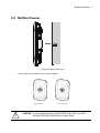
Place the large corner of each of the case’s mount slots over the screw heads.
Slide the case down along the mounting surface to hang the mount slots on the screw heads.
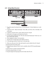
Attach appropriate antennas to the connectors.
Attach the Ethernet cable to the unit and to a controller with an 802.3af compatible power
source.
10. Verify the unit has power by observing that the LEDs are lit or flashing.
2.7 External Antenna Model Suspended Ceiling Tile (Plenum) Mount
Instructions
Ceiling mount requires placing the AP6532 Access Point above a suspended ceiling and installing the
provided light pipe for viewing the status lights of the unit.
NOTE
Notes or warnings about suspended ceiling mounts apply to all
installations where the unit is placed on suspended ceiling tile. The case
has a safety wire tie point for a standard safety wire.
CAUTION
!
Motorola Solutions does not recommend mounting the AP6532
Access Point directly to any suspended ceiling tile with a thickness
less than 12.7mm (0.5in.) or a suspended ceiling tile with an
unsupported span greater than 660mm (26in.). Motorola Solutions
strongly recommends fitting the AP6532 Access Point with a safety
wire suitable for the specific installation. The safety wire should be a
standard ceiling suspension cable or equivalent steel wire between
1.59mm (.062in.) and 2.5mm (.10in.) in diameter.
This placement requires installation of the provided light pipe for viewing the status lights of the unit.
2.7.1 Suspended Ceiling Mount Hardware
•
•
•
Light pipe
Badge for light pipe
Safety wire (recommended) and security cable (optional)