1
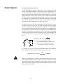
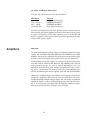
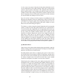
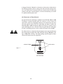
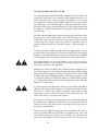
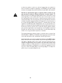
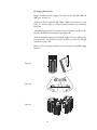
APL-220, APL-500, & APL-800
SELF-POWERED FULL-RANGE
SPEAKER SYSTEM MANUAL
© 2001 Apogee Sound International
Specifications subject to change without notice.
55-0048-01D 0711
Notice
Every effort was made to ensure that the information in this guide was complete and accurate at the time of
printing. However, information is subject to change.
IMPORTANT SAFETY INFORMATION
WARNING: To Reduce The Risk of Fire Or Electric Shock, Do Not Expose This Apparatus To Rain Or
Moisture.
Always
1.
2.
3.
4.
5.
6.
7.
8.
9.
10.
11.
12.
13.
follow these basic safety precautions when installing and using the unit:
Read these instructions.
Keep these instructions.
Heed all warnings.
Follow all instructions.
Do not use this apparatus near water.
Clean only with dry cloth.
DO NOT block any ventilation openings. Install in accordance with the manufacturer's instructions.
Do not install near any heat sources such as radiators, heat registers, stoves, or other apparatus
(including amplifiers) that produce heat.
Do not defeat the safety purpose of the polarized or grounding-type plug. A polarized plug has two
blades with one wider than the other. A grounding-type plug has two blades and a third grounding
prong. The wide blade, or the third prong, are provided for your safety. If the provided plug does not
fit into your outlet, consult an electrician for replacement of the obsolete outlet.
Protect the power cord from being walked on or pinched, particularly at plugs, convenience
receptacles, and the point where they exit from the apparatus.
Only use attachments/accessories specified by the manufacturer.
Unplug this apparatus during lightning storms or when unused for long periods of time.
Refer all servicing to qualified service personnel. Servicing is required when the apparatus has been
damaged in any way, such as power-supply cord or plug is damaged, liquid has been spilled or objects
have fallen into the apparatus, the apparatus has been exposed to rain or moisture, does not operate
normally, or has been dropped.
CAUTION
RISK OF ELECTRIC SHOCK
DO NOT OPEN
CAUTION: TO PREVENT THE RISK OF ELECTRIC
SHOCK, DO NOT REMOVE COVER (OR BACK). NO
USER-SERVICEABLE PARTS INSIDE. REFER SERVICING
TO QUALIFIED PERSONNEL.
The lightning flash with arrowhead symbol, within an equilateral triangle, is intended to alert the user to the presence of uninsulated
"dangerous voltage" within the product's enclosure that may be of
sufficient magnitude to constitute a risk of electric shock to persons.
The exclamation point within an equilateral triangle is intended to
alert the user to the presence of important operating and maintenance (servicing) instructions.
2
Table of Contents
Precautions & Safety Notes . . . . . . . . . . . . . . . . . . . . . . . . . . 4
Introduction . . . . . . . . . . . . . . . . . . . . . . . . . . . . . . . . . . . . . . . 7
The Concept of Integration. . . . . . . . . . . . . . . . . . . . . . . . . . . 7
AC Power Requirements . . . . . . . . . . . . . . . . . . . . . . . . . . . . 9
Audio Signals . . . . . . . . . . . . . . . . . . . . . . . . . . . . . . . . . . . . . 14
Amplifiers . . . . . . . . . . . . . . . . . . . . . . . . . . . . . . . . . . . . . . . . 15
Installation . . . . . . . . . . . . . . . . . . . . . . . . . . . . . . . . . . . . . . . 16
Signal Processing. . . . . . . . . . . . . . . . . . . . . . . . . . . . . . . . . . 18
Using the APL-220, -500, and -800 . . . . . . . . . . . . . . . . . . . . 23
Troubleshooting & Field Repairs . . . . . . . . . . . . . . . . . . . . . . 32
Accessories . . . . . . . . . . . . . . . . . . . . . . . . . . . . . . . . . . . . . . 35
Troubleshooting Chart . . . . . . . . . . . . . . . . . . . . . . . . . . . . . . 36
Amplifier Back Panel . . . . . . . . . . . . . . . . . . . . . . . . . . . . . . . 37
Line Drawings. . . . . . . . . . . . . . . . . . . . . . . . . . . . . . . . . . . . . 39
Specifications . . . . . . . . . . . . . . . . . . . . . . . . . . . . . . . . . . . . . 42
Warranty Information . . . . . . . . . . . . . . . . . . . . . . . . . . . . . . . 43
3
Precautions &
Safety Notes
English
• To reduce the risk of electric shock, disconnect the AC mains power cable
before installing audio cable. Reconnect the power cord only after making all
signal connections.
• Connect the loudspeaker only to a three-pole, three-wire grounding mains
receptacle. The receptacle must be connected to a fuse or circuit breaker.
Connection to any other type of receptacle poses a shock hazard and may
violate local electrical codes.
• Do not install the speaker in wet or humid locations without using weather protection equipment from Apogee Sound International.
• Do not allow water or any foreign object to get inside the loudspeaker. Do
not put objects containing liquid on, or near, the unit.
• To reduce the risk of overheating the loudspeaker, avoid exposing it to
direct sunlight. Do not install the unit near heat-emitting devices or appliances, such as a room heater or stove.
• The loudspeaker contains potentially hazardous voltages. Do not attempt to
disassemble the unit. The unit contains no user-serviceable parts. Repairs
should be performed only by factory trained service personnel.
Francais
• Pour réduire le risqué d’électrocution, débrancher la prose principale de
l’haut-parleur, avant d’installer le cable d’interface allant à l’audio. Ne
rebrancher le bloc d’alimentation qu’après avoir effectué toutes les connections.
• Branchez l’haut-parleur dans une prise de courant à 3 dérivations (deux
pôles et la terre). Cette prose doit être munie d’une protection adéquate
(fusible ou coupe-circuit). Le branchement dans tout autre genre de prose
pourrait entraîner un risqué d’électrocution et peut constituer une infraction
à la réglementation locale concernant les installations électriques.
• Ne pas installer l’haut-parleur dans un endroit où il y a de l’eau humidité
excessive.
• Ne pas laisser de l’eau ou tout objet pénétrer dans l’haut-parleur. Ne pas
placer decipients contenant un liquide sur cet appareil, ni à proximité de
celuici.
• Pour éviter une surchauffe de l’haut-parleur, conserver-la à l’abri du soleil.
Ne pas installer à proximité d’appareils dégageant de la chaleur tells que radiateurs ou appareils de chauffage.
4
• Ce haut-parleur contient des circuits haute tension présentant un danger.
Ne jamais essayer de le démonter. Il n’y a aucun composant qui puisse être
réparé par l’utilisateur. Toutes les reparations doivent être effectuées par du
personnel qualifié et agree par le constructeur.
Deutsch
• Um die Gefahr eines slektrischen Schlages auf ein Minimum zu reduzieren,
den Lautsprecher vom Stromnetz trennen, bevor ggf. Ein AudioSchnittstellensignalkabel angeschlossen wird. Das Netzkabel erst nach
Herstellung aller Signalverbindungen wieder einstecken.
• Der Lautsprecher an eine geerdete zweipolige Dreiphasen-Netzsteckdose
anschließen. Die Steckdose muß mit einem geeigneten Abzweigschutz
(Sicherung oder Leistungsschalter) verbunden sein. Der Anschluß der unterbrechungsfreien Stromversorgung an einen anderen Steckdosentyp kann zu
Stromschlägen führen und gegen die örtlichen Vorschriften verstoßen.
• Der Lautsprecher nict an einem Ort aufstellen, an dem sie mit Wasser oder
übermäßig hoher Luftfeuchtigkeit in Berührung kommen könnte.
• Darauf achet, daß weder Wasser noch Fremdkörper in das Innere den
Lautsprecher eindringen. Keine Objekte, die Flüssigkeit enthalten, auf oder
neben die unterbrechungsfreie Stromversorgung stellen.
• Um ein Überhitzen dem Lautsprecher zu verhindern, das Gerät vor direkter Sonneneinstrahlung fernhalten und nicht in der Nähe von wämeabstrahlenden Haushaltsgeräten (z.B. Heizgerät oder Herd) aufstellen.
• Im Inneren diesem Lautsprecher herrschen potentiell gefährliche
Spannungen. Nicht versuchen, das Gerät zu öffnen. Es enthält keine vom
Benutzer reparierbaren Teile. Reparaturen dürfen nur von ausgebildetem
Kundenienstpersonal durchgeführt werden.
Español
• Para reducir el riesgo de descarga eléctrica, desconecte de la red el altoparlante antes de instalar el cable de señalización de interfaz de la segnale.Vuelva
a conectar el conductor flexible de alimentación solamente una vez efectuadas todas las interconexiones de señalizatción.
• Conecte el altoparlante a un tomacorriente bipolar y trifilar con neutro de
puesta a tierra. El tomacorriente debe estar conectado a la protección de
derivación apropiada (ya sea un fusible o un disyuntor). La conexión a
cualquier otro tipo de tomacorriente puede constituir peligro de descarga
eléctrica y violar los códigos eléctricos locales.
5
• No instale el altoparlante en lugares donde haya agua o humedad excesiva.
• No deje que en el altoparlante entre agua ni ningún objeto extraño. No
ponga objetos con líquidos encima de la unidad ni cerca de ella.
• Para reducir el riesgo de sobrecalentamiento, no exponga la inidad a los
rayos directos del sol ni la instale cerca de artefactos que emiten calor, como
estufas o cocinas.
• Este altoparlante contiene niveles de voltaje peligrosos en potencia. No
intente desarmar la unidad, pues no contiene piezas que puedan ser repardas por el usuario. Las reparaciones deben efectuarse únicamente por parte
del personal de mantenimiento capacitado en la fábrica.
6
Introduction
Apogee Powered Loudspeaker Systems are highly-engineered products that
combine advanced-technology amplifiers, sophisticated signal processing, and
state-of-the-art drivers housed in rugged, roadworthy loudspeaker enclosures. They are suitable for a wide variety of applications, ranging from
portable use for shows and events in all types of venues to permanent installations in auditoriums, churches, theaters, stadiums, meeting rooms, boardrooms, and similar locations.
The APL-220, APL-500, and APL-800 are compact, bi-amplified speaker systems capable of providing clean, undistorted sound at very high output levels. They easily form acoustically-correct arrays when used in multiples.
Although deceptively small in size, they are capable of fulfilling an astonishingly wide range of professional sound reinforcement requirements due to
their wide-range response, predictable pattern control, excellent sonic quality, and easy arrayability.
Apogee powered products are exhaustively engineered and finely crafted.
They will provide years of trouble-free service if care is taken in their use and
maintenance. It is recommended that you read this manual and retain it in a
convenient location for future reference.
The Concept
of Integration
Why a Powered Loudspeaker?
Apogee’s powered speaker systems further the company’s original concept
of processor-based loudspeakers. By combining advanced electronic signal
processing with precisely matched amplifiers, and integrating this package
into the speaker enclosure itself, a number of engineering improvements
result. Some of these are:
• The internal signal processor corrects driver and enclosure anomalies, and
provides required crossovers, time-domain alignment, and protection circuits.
• The amplifier’s power output, headroom, frequency response and dynamic
range are optimized for each model of loudspeaker system.
• The gain structure of the signal processor and amplifiers are always perfectly matched.
• An integrated speaker system is able to use voltage sensors to provide
information to the processor’s protection circuits. The result is more accurate control of the drivers’ mechanical and thermal limits, and therefore
better protection under abusive conditions.
• The amplifier output cables are kept to very short lengths, thereby reducing cable losses to nearly zero.
7
These engineering advancements result in the following benefits:
• All aspects of the loudspeaker system’s performance are maximized. Sonic
quality, power output capability, flatness of response, distortion, and behavior under abusive conditions meet remarkably high standards.
• Reliability is increased because the internal amplifiers deliver appropriate
power levels to the drivers, without danger of over-powering or underpowering.
• Setup is quick and easy - all key circuitry is self-contained and factoryinterconnected. There is no longer a need for the time-consuming mounting and wiring of processors and amplifiers in outboard rack enclosures.
• Powered speakers save valuable truck and stage space previously allocated
for amplifier racks. Load-ins and load-outs are quicker and easier than with
conventional systems.
• Powered speakers weigh less than equivalent non-powered speakers and
amp racks, resulting in easier handling and reduced shipping costs.
• Powered speakers cost less and offer higher value than the equivalent
non-powered speaker, processor, amplifier, and rack combination.
8
AC Power
Requirements
(1) AC Power Connector and Cable
The APL-220, -500, and -800 each use a PowerCon® 3-pole AC mains connector for their power inlet (see Figure #1). When joined to the mating
PowerCon connector supplied with the AC line cord, the connector pair
locks in place to prevent inadvertent disconnection. PowerCon connectors
are durable, inexpensive, and readily obtainable.
Insertion
Figure 1
Removal
The AC PowerCon cable assembly provided with your APL-220, -500, or -800
is equipped with an AC mains plug compatible with the power service in the
country of sale. If you need to change this plug or to construct special purpose power cables, the wiring must follow the convention shown in Figure #2.
Brown - Hot
Figure 2
Blue - Neutral
Yellow/Green - Earth Ground
9
Ground
Hot
Figure 3
Neutral
Interior of PowerCon connector showing the wiring terminal
All AC power plugs must always be of the 3-pole grounding type.
DO NOT DEFEAT THE GROUND CONNECTION BY USING
AN AC GROUND LIFT ADAPTER, OR BY CUTTING THE
GROUND PIN OF THE AC POWER PLUG.
(2) Voltage Range
The APL-220, -500, and -800 use advanced, high efficiency, intelligent, power
supplies. A convenient external switch allows for easy conversion between
115V AC and 230V AC. In the 115V AC setting, the allowable line voltage
range is 90V AC to 132V AC and in the 230V AC setting, the allowable range
is 190V AC to 265V AC.
(3) Current Requirements
All power amplifiers require sufficient current for proper operation and the
amplifiers designed into Apogee powered loudspeakers are no exception.
Chart #1 shows the required current for one APL-220, -500, and -800 at two
standard international working voltages (120 & 240V AC). Because current
drain is ultimately a function of the program source, Chart #1 shows both
the theoretical maximum, and what can be expected under typical high-level
program conditions:
Chart 1
APL-220, -500, and -800
120V AC
240V AC
Max. Continuous Amperes
6.0 ARMS
3.0 ARMS
Typical Program Conditions
4.0 ARMS
2.0 ARMS
10
We recommend powering no more than 2 APL-220, -500, or -800s from a
single 15A, 120V AC circuit, and no more than 3 APL-220, -500, or -800s from
a single 20A, 120V AC circuit, thereby allowing a margin for low voltages.
The advanced design of the APL-220, -500, and -800 allow them to function
properly over a wide range of voltages. The power supplies are designed to
perfectly maintain the amplifier’s internal bus voltage throughout this range,
with no degradation in performance. However, it is important to be aware
that the unit will draw more current if the power line voltage decreases.
Under full-power conditions, one APL-220, -500, or -800 can draw as much
as 720 watts. At 90V AC, this equates to 8.0 Amperes whereas at 240V AC,
the current demand is only 3 Amperes, to produce the same amplifier power.
Power (Wattage) is simply voltage (RMS) times current (RMS) or:
P=V x I
You can easily calculate the power demand at any line voltage by using the
following formula:
P/V = I
For example: if the line voltage is 208V AC, a single APL-500 at maximum
power (720 Watts) will draw 3.46 Amperes (720 / 208 = 3.46). This calculation is useful for determining appropriate cables to use with your powered
speaker system.
To determine the total current requirement for a system of powered loudspeakers, simply add their Maximum Continuous RMS Currents together,
then calculate a safety margin of 25% or greater.
If special length AC cables are required for your powered speakers, they
should be constructed of durable, high-quality portable cordage such as S,
SO, or SJO type.
11
Chart 2 provides the basic guidelines of The National Electric Code for four
common gauges of copper wire related to permissible load in amperes.
Chart 2 applies to three-conductor portable cordage of the types S, SO, SP,
SPT, SJ, and SJO, which are typically rated at a maximum operating temperature of 140°F (60° C). (NOTE: Operating temperature is the heat generated within the cable from the voltage drop added to the ambient temperature.) Chart 2 covers ambient temperatures of 86°F (30°C), 104°F (40°C),
& 122°F (50°C).
For safety reasons, the maximum ratings in the table below should never
be exceeded.
Ambient Temperature
86°F (30°C)
104°F (40°C)
122°F (50°C)
14
15 A
12.3 A
6.9 A
12
20 A
16.4 A
8.7 A
10
25 A
20.5 A
14.5 A
8
35 A
28.7 A
20.3 A
AWG#
Chart 2
(NOTE: AWG stands for American Wire Gauge.)
As you can readily see from Chart 2, the maximum permissible current ratings decrease rapidly as the ambient temperature rises. Carefully consider
the ambient temperature in which the equipment will be used when determining appropriate wire gauge size.
(4) Voltage Drop
Another important consideration in determining appropriate wire gauge is
the voltage drop that occurs across the cable’s resistance. This is a function
of the gauge and the length of the conductors, the current drawn by the load,
and the starting AC mains voltage. Generally, the permissible voltage drop
should not exceed 2.5% of the working voltage for audio loads. Although the
APL-220, -500, and -800 power supplies automatically compensate for voltage drops down to 90V AC in the 115V AC setting and 190V AC in the 230V
AC setting, it’s important to provide adequate power to the powered loudspeaker by choosing appropriate cable sizes. A drop in voltage across the
power cable will cause the intelligent power supplies to draw more current
thereby causing the voltage to decrease even more. If the voltage drops
below 90V AC or 190V AC, damage may occur to the unit.
Chart 3 shows voltage drop as a percentage of the nominal working voltage
for typical lengths of cables at 120V AC and 240V AC.The shaded areas show
cable lengths and loads that result in 2.5% or less of voltage drop.
12
POWER CABLE VOLTAGE DROP (IN PERCENTAGE OF NOMINAL VOLTAGE)
Chart 3
#14 AWG, 120V AC
Length in Feet 5A
25'
0.6%
50'
1.2%
75'
1.8%
100'
2.4%
125'
3.0%
150'
3.6%
175'
4.3%
200'
4.9%
225'
5.5%
250'
6.1%
275'
6.7%
300'
7.3%
10A
1.2%
2.4%
3.6%
4.9%
6.1%
7.3%
8.5%
9.7%
10.9%
12.2%
13.4%
14.6%
15A
1.8%
3.6%
5.5%
7.3%
9.1%
10.9%
12.8%
14.6%
16.4%
18.2%
20.1%
21.9%
20A
2.4%
4.9%
7.3%
9.7%
12.2%
14.6%
17.0%
19.5%
21.9%
24.3%
26.8%
29.2%
#14 AWG, 240V AC
Length in Feet 5A
25'
0.3%
50'
0.6%
75'
0.9%
100'
1.2%
125'
1.5%
150'
1.8%
175'
2.1%
200'
2.4%
225'
2.7%
250'
3.0%
275'
3.3%
300'
3.6%
10A
0.6%
1.2%
1.8%
2.4%
3.0%
3.6%
4.3%
4.9%
5.5%
6.1%
6.7%
7.3%
15A
0.9%
1.8%
2.7%
3.6%
4.6%
5.5%
6.4%
7.3%
8.2%
9.1%
10.0%
10.9%
20A
1.2%
2.4%
3.6%
4.9%
6.1%
7.3%
8.5%
9.7%
10.9%
12.2%
13.4%
14.6%
#12 AWG, 120V AC
Length in Feet 5A
25'
0.4%
50'
0.8%
75'
1.1%
100'
1.5%
125'
1.9%
150'
2.3%
175'
2.7%
200'
3.1%
225'
3.4%
250'
3.8%
275'
4.2%
300'
4.6%
10A
0.8%
1.5%
2.3%
3.1%
3.8%
4.6%
5.4%
6.1%
6.9%
7.7%
8.4%
9.2%
15A
1.1%
2.3%
3.4%
4.6%
5.7%
6.9%
8.0%
9.2%
10.3%
11.5%
12.6%
13.8%
20A
1.5%
3.1%
4.6%
6.1%
7.7%
9.2%
10.7%
12.3%
13.8%
15.3%
16.8%
18.4%
#12 AWG, 240V AC
Length in Feet 5A
25'
0.2%
50'
0.4%
75'
0.6%
100'
0.8%
125'
1.0%
150'
1.1%
175'
1.3%
200'
1.5%
225'
1.7%
250'
1.9%
275'
2.1%
300'
2.3%
10A
0.4%
0.8%
1.1%
1.5%
1.9%
2.3%
2.7%
3.1%
3.4%
3.8%
4.2%
4.6%
15A
0.6%
1.1%
1.7%
2.3%
2.9%
3.4%
4.0%
4.6%
5.2%
5.7%
6.3%
6.9%
20A
0.8%
1.5%
2.3%
3.1%
3.8%
4.6%
5.4%
6.1%
6.9%
7.7%
8.4%
9.2%
#10 AWG, 120V AC
Length in Feet 5A
25'
0.2%
50'
0.5%
75'
0.7%
100'
1.0%
125'
1.2%
150'
1.4%
175'
1.7%
200'
1.9%
225'
2.2%
250'
2.4%
275'
2.6%
300'
2.9%
10A
0.5%
1.0%
1.4%
1.9%
2.4%
2.9%
3.4%
3.8%
4.3%
4.8%
5.3%
5.8%
15A
0.7%
1.4%
2.2%
2.9%
3.6%
4.3%
5.0%
5.8%
6.5%
7.2%
7.9%
8.7%
20A
1.0%
1.9%
2.9%
3.8%
4.8%
5.8%
6.7%
7.7%
8.7%
9.6%
10.6%
11.5%
#10 AWG, 240V AC
Length in Feet 5A
25'
0.1%
50'
0.2%
75'
0.4%
100'
0.5%
125'
0.6%
150'
0.7%
175'
0.8%
200'
1.0%
225'
1.1%
250'
1.2%
275'
1.3%
300'
1.4%
10A
0.2%
0.5%
0.7%
1.0%
1.2%
1.4%
1.7%
1.9%
2.2%
2.4%
2.6%
2.9%
15A
0.4%
0.7%
1.1%
1.4%
1.8%
2.2%
2.5%
2.9%
3.2%
3.6%
4.0%
4.3%
20A
0.5%
1.0%
1.4%
1.9%
2.4%
2.9%
3.4%
3.8%
4.3%
4.8%
5.3%
5.8%
#8 AWG, 120V AC
Length in Feet 5A
25'
0.2%
50'
0.3%
75'
0.5%
100'
0.6%
125'
0.8%
150'
0.9%
175'
1.1%
200'
1.2%
225'
1.4%
250'
1.5%
275'
1.7%
300'
1.8%
10A
0.3%
0.6%
0.9%
1.2%
1.5%
1.8%
2.1%
2.4%
2.7%
3.0%
3.3%
3.6%
15A
0.5%
0.9%
1.4%
1.8%
2.3%
2.7%
3.2%
3.6%
4.1%
4.5%
5.0%
5.5%
20A
0.6%
1.2%
1.8%
2.4%
3.0%
3.6%
4.2%
4.8%
5.5%
6.1%
6.7%
7.3%
#8 AWG, 240V AC
Length in Feet 5A
25'
0.1%
50'
0.2%
75'
0.2%
100'
0.3%
125'
0.4%
150'
0.5%
175'
0.5%
200'
0.6%
225'
0.7%
250'
0.8%
275'
0.8%
300'
0.9%
10A
0.2%
0.3%
0.5%
0.6%
0.8%
0.9%
1.1%
1.2%
1.4%
1.5%
1.7%
1.8%
15A
0.2%
0.5%
0.7%
0.9%
1.1%
1.4%
1.6%
1.8%
2.0%
2.3%
2.5%
2.7%
20A
0.3%
0.6%
0.9%
1.2%
1.5%
1.8%
2.1%
2.4%
2.7%
3.0%
3.3%
3.6%
13
Audio Signals
(1) Input Impedance and Level
The APL-220, -500, and -800 were designed to receive a balanced-line signal
on their 3-pin female XLR type connector. They are also equipped with a 3pin Male XLR output connector, labeled “loop-through,” intended for the
purpose of daisy-chaining multiple powered speakers together on a common
signal feed.These input and output connectors are hard-wired in parallel; that
is to say, no active or passive buffer exists between the two connectors, they
are simply wired in parallel. This means that the loop-through connector will
always remain functional, even if AC power is interrupted to a speaker
“upstream” of other speaker(s) on the same feed circuit.
The input impedance is 35k-ohm, active balanced, and is intended to receive
a nominal +3 dBv input level (+3 dBv = full power). Because it’s common
practice to loop quite a few powered speakers together on a shared feeder
circuit, care must be taken to insure that the signal source is capable of driving the group of powered loudspeakers. For example, ten APL-500 speakers
present a 1k-ohm load to the signal source. This is well within the capability
of most line-level output drivers, but depending on the output impedance of
the source, some loss in level may occur. The formula to calculate such
loss is:
RIx
Voltage Loss (dB) = 20 * Log (RIx +RS)
[
RS
VS
VI
RIx
]
Where: RS = Source Equipment Output Impedance
RIx = Combined Input Impedance of all APL Speakers
Note: VS = Unloaded Source Equipment Signal Voltage
VI = Loaded Signal Input Voltage to APL Speakers
For example, let’s say you’re driving ten APL-500 speakers with a 100-ohm
source impedance. The formula to calculate loss would then be:
1000
Voltage Loss (dB) = 20 * Log (1000+100 ) = – 0.83 dB
[
]
NOTE: It is important to be aware of the potential losses that may occur
from combining multiple powered speakers on the same feed circuit. This is
particularly important when attempting to adjust audio levels among a large
system that employs multiple feed circuits with different numbers of powered speakers on each feed.
14
(2) Input and Output Connectors
The input and output connectors are wired as follows:
Function
Earth & Chassis Ground
DIFFERENTIAL INPUT
DIFFERENTIAL INPUT
Earth & Chassis Ground
XLR Pin #
Pin 1
Pin 2 Signal +
Pin 3 Signal Connector Case
A positive signal applied to pin 2 of the XLR will result in a positive acoustic
pressure wave (excursion) appearing at the front of the drivers in the speaker system. Conversely, a positive signal appearing at pin 3 of the XLR will
result in a negative acoustic pressure wave (recursion) appearing at the front
of the speaker system’s drivers.
Amplifiers
Overview
The internal amplification package consists of dual, fully-independent power
supplies and dual, fully-independent 500-watt RMS, 1600-watt peak, digital
amplifiers. One channel is utilized for the low frequency driver and the other
channel is used for the high frequency driver, hence the term "bi-amped."
These amplifiers and power supplies use numerous, proprietary design features that result in extremely low distortion, high reliability, and a very low
heat by-product. No fans are used or needed, eliminating the risk of a
mechanical device becoming noisy during a quiet performance due to bearing wear or contamination. The absence of fans also greatly simplifies maintenance, by eliminating the need to regularly check and clean air intake filters.
Unlike some competing designs, the amplifiers used in Apogee powered loudspeakers are designed to drive normal 4- and 8-ohm loads. Due to an exceptionally high voltage swing, the Apogee design does not require unusually low
impedance drivers in order to develop full power. Very low impedance drivers (1- or 2-ohm) have a low BL-product and typically exhibit poor dampening and transient response, resulting in a loss of clarity.
15
The power supplies are robust and reliable. They each provide 650 watts of
continuous power, giving the system considerable headroom above its nominal 500 WRMS per channel rating. Each of the two amplifiers is capable of
delivering 500 WRMS, and as much as 1600 watts of instantaneous burst
power.
Why the large difference between WRMS and instantaneous power? WRMS
is a measurement that occurs over a long period of time and is limited by
many factors including thermal considerations. Instantaneous power is a simple function of the peak voltage supplied to the speaker driver and the
impedance of the driver. Apogee’s APL series' amplifiers use a 80-volt bus (V)
with a 4-ohm driver (R). The instantaneous power calculation is:
2
Pi = V /R
or
2
80 /4 = 1600W
An amplifier's ability to handle musical transients is a function of its instantaneous power capability.
Installation
When installing and using the APL-220, -500, or -800, some simple precautions should be followed. These include:
(1) Maintain Proper Air Flow
The APL-220, -500, and -800 are convection-cooled devices. Convection
cooling is more dependable than forced air cooling because fans are often
unreliable and require high maintenance. Apogee's APL-220, -500, and -800
do not need filter changes to protect the circuitry from contamination by
dust and dirt. The aluminum heat sink mounted on the rear surfaces provides
primary cooling of the system. Care must be taken to locate the loudspeaker away from heat registers, heat-generating appliances, lighting equipment,
and any other apparatus that could raise the temperature of the nearby air.
The APL-220, -500, and -800 require unimpeded air circulation in order to
function properly (this is especially important when multiple units are used
in stacked and/or tight-pack configurations). The APL’s rear surface should be
located at least 12" away from walls and/or ceilings. Sunlight and artificial
lighting, especially of the high intensity or theatrical type, should never be
allowed to shine directly on the heat sink.
16
(2) Ambient Temperature
The APL-220, -500, and -800 are designed to be used in ambient temperatures ranging from 32°F - 113°F (0°C - 45°C). Higher or lower temperatures
could cause system shutdown or result in early component failure. When
used outdoors on a hot day, take precautions to avoid direct sunlight on the
rear heat sink. Direct, intense sunlight can raise the temperature of the heat
sink to a point where the amplifiers may automatically shutdown to avoid
permanent damage.
(3) Convection Cooling and use in Horizontal Position
The APL-220, -500, and -800 are convection-cooled. The heat generated by the
internal amplifiers and power supplies is conducted to the rear heat sink and
transferred to the air by means of natural convection. Convection occurs from the
change in density of air molecules as they are heated, creating a natural airflow
from the relatively cool bottom of the heat sink to the warmer top area. Air flows
through the cooling fins, increasing in temperature as it rises.
If the APL-220, -500, or -800 are used in a horizontal position, air will not
flow as readily through the fins. When placed horizontally, the fins act as
obstacles to the airflow, and cooling efficiency is reduced. In moderate ambient temperatures, this will not usually cause a problem. However, it is prudent
to test the system under maximum power conditions at the highest ambient
temperature that will be encountered, in order to verify if cooling is adequate
to prevent system shutdown. Since the temperature of the heat sink will
increase over time as the system is used, this test should be conducted for a
time period equivalent to the actual intended duration of use.
(4) More About Heating and Cooling
The APL-220, -500, and -800 have a relatively complex thermal dynamic system. They contain several heat sources (amplifiers, power supplies, and drivers) that generate significant heat but only when program material is being
reproduced. They are cooled primarily through convection; and secondarily,
by a small degree of air movement generated by the cone drivers.
Because the heat output of the system is directly proportional to the duration and nature of the program material, the system may not reach thermal
stability for several hours after it is activated. For this reason, it is important
to test the system under actual conditions of use if questionable conditions
are present. Questionable conditions include:
(a) ambient temperature at or above the maximum rating
(b) intense sunlight or artificial light shining on the heat sink
(c) program material that runs for many hours without pause
(d) combinations of the above
17
Here’s a hypothetical example of what to look out for. An APL-500
might be set up outdoors in 85°F (29°C) temperature with sunlight shining
partially on the rear panel. Let’s assume it is tested during a 30-minute sound
check and all is well. Later that day, the ambient temperature rises to 99°F
(37°C) and the sunlight is now shining directly on the rear of the loudspeaker. The show starts, featuring dance tracks with no pause between song titles.
Under such extreme conditions, it is entirely possible that after a period of
service, the loudspeaker will shut off to protect itself from excessive heat.
Problems, such as the one described above, can be avoided by shading the
heat sink from direct sunlight.
Signal Processing
(1) Basic Concept
The APL-220, -500, and -800 use a highly-advanced signal processor contained entirely within the unit. The processor provides the functions of an
eighth-order (48 dB/octave) electronic crossover, fixed equalization to compensate for driver/enclosure anomalies, time delay to acoustically align the
low and high drivers, and advanced protective limiting circuits. It also provides
a low-frequency alignment circuit that acts synergistically with the enclosure’s
ports. This serves to extend the bass response well below that of a conventional enclosure of a similar size. All circuits in the audio path utilize the highest quality, most up-to-date semi-conductor technologies available today.
The processor is the key to the extraordinary sound quality of the loudspeaker system. Unlike generic crossovers, either digital or analog, the APL
processor was carefully designed in tandem with the amplifiers, the drivers,
and the enclosure to provide optimum performance.
(2) Functional Description of Integrated Design Philosophy
One example of integrated design is the deployment of the high-frequency
equalization circuit. Here’s how it works: The loudspeaker’s high-frequency
driver uses a composite diaphragm material that is capable of smoothly
reproducing the extreme high frequencies, but not with the same sensitivity
as that of the lower portion of the spectrum. This is because the material is
highly damped and exceptionally free from resonance, especially when compared to the typical distortion-prone aluminum and titanium diaphragms
used by most manufacturers. This same property, however, causes the driver
to exhibit a linear fall-off in its high-frequency response.The driver would not
be very useful in a two-way, non-processor based system, because it would
require a very specific compensation filter, not available from most generic
equalizers, to restore its response to flat.
18
Many product designers would summarily reject such a driver, because its frequency response is not inherently flat, even though its response is exceptionally linear and its distortion extremely low.
Now the synergy of integrated design comes into play. The processor is
designed to correct the driver’s deviation from flatness with a proprietary
high-frequency filter circuit that flattens the driver’s response curve.
Simulating the effect of this particular circuit would be difficult, to say the
least, with a generic loudspeaker controller. In fact, if using a generic digital
controller, the required curve would most likely collide with the controller’s
anti-aliasing filter, making it impossible to duplicate. Does that mean this
unusual driver is not a good choice for a professional loudspeaker? Not at
all! On the contrary, when coupled with the processor’s compensation circuit, the driver exhibits a flat response and the lowest distortion of any highpower, horn-loaded compression driver that we know of. The driver merely
required a properly designed compensation circuit to achieve its potential. It’s
that simple.
Here’s another way of looking at it. The compensation circuit is similar to the
pre-emphasis and de-emphasis circuits used for decades in analog tape
recorders. Only in the case of the HF driver, instead of reducing tape noise,
distortion is reduced. The de-emphasis side of the equation is really the
mechanical function of the driver's HF roll-off, and the pre-emphasis is the
EQ compensation circuit. The resultant reduction in distortion comes from
the highly damped nature of the diaphragm. A damped material is not prone
to resonance and, therefore, does not produce the harmonic distortion
products of a resonant material.
(3) Driver Protection
Apogee APL-Series speakers utilize a special, highly-evolved set of limiter
parameters and controls. Multiple limiters are used simultaneously with
attack, release, integration time, and slopes that have been carefully matched
to the individual speakers thermal and mechanical limits over time.
All of this occurs without compromising dynamic range or otherwise unnaturally compressing the program material. The protection circuits only act
when the drivers would otherwise be damaged and, therefore, are exceptionally transparent. They are effectively “out of circuit” when below the
threshold of engagement. The result is extremely clean sound quality, with
effective protection of potential damage to the drivers under abusive
conditions.
19
A clipping LED indicator is located on the rear panel. This LED will illuminate
when the speaker is several dB into limiting and indicates maximum operating level has been reached. It is not uncommon to see these LEDs illuminate
regularly, such as on downbeats and crescendos.
If the LEDs appear to be "on" more than "off " (i.e., if they are continuously
flashing or glowing at a steady state), the loudspeaker system is being pushed
too hard for its size and power output capability. To correct this, reduce the
drive level to the speaker system, or install additional speakers to achieve the
SPL (Sound Pressure Level) required for the application.
(4) A Word About Limiters
Properly designed protective limiters can do wonders to help prevent driver
damage and extend normal driver life, but they are by no means a panacea.
Apogee limiters do not exhibit “brick-wall” characteristics because such limiters
seriously degrade sound quality. Apogee’s intelligently engineered limiter circuits
provide an excellent measure of protection, while maintaining sonic purity.
Apogee's limiter circuits are capable of effectively reducing program levels
that would otherwise damage the system’s drivers. This takes place with little
or no loss of sonic quality or dynamic range, because the circuits are designed
so that they only engage when driver non-linearity or driver damage would
otherwise occur. However, when a limiter is pushed well past its threshold of
engagement to the point where it is continually “in circuit”, by nature it
increases the duty-cycle of the program material.This happens because, as the
limiter decreases peak amplitudes, RMS values increase, causing the drivers to
heat beyond normal. Additional circuits could be employed to reduce levels
and “clamp” the output of the system, but such circuits would represent a
high level of intervention and be very audible in their action. The proper solution is for the operator to recognize that the system is being pushed past its
capabilities and either reduce the operating level or add additional speaker
systems to provide the desired Sound Pressure Level (SPL).
(5) High-Pass Filter (HPF) Switch
The APL-220, -500, and -800 are equipped with a switchable High-Pass Filter.
The filter is of the 12 dB/octave type with a corner frequency of 80 Hz. The
High-Pass Switch is intended to be used when the speaker system is not
required to produce full-range output, such as in downfill, front fill, and other
band-limited applications. By using the High-Pass Filter Switch, the speaker
system can be driven approximately 6 dB harder before LF peak and LF RMS
limiters are engaged. The switch is located on the rear panel below the Input
XLR connector. It is recessed with only a small portion accessible, so that it
cannot easily be changed inadvertently.
20
(6) When to Use the High-Pass Filter Switch
The High-Pass Filter Switch is very effective when the APL-220, -500, and 800 are utilized with subwoofers, or other larger speaker systems.
For example, a system may be made up primarily of FH-4s, 3X3s, or other
large concert type speakers, with APL-500 speakers flown below them for
downfill. Additional APL-500 speakers might be located on the apron of the
stage to fill the front rows where direct coverage by the larger speakers is
absent. More APL-500 speakers might be located towards the rear of the
venue as "delay fills." In all three cases, using the High-Pass Filter Switch is
recommended. There is probably enough low-frequency energy already present in the venue from the larger speakers and subwoofers, so reducing the
low-frequency output of the APL-500 fill speakers should improve the overall sound quality as well as allow the APL-500 speakers to be operated safelyat higher levels.
(7) Care in Using the High-Pass Filter Switch
Because the action of the High-Pass Filter Switch cannot easily be reversed
without direct access to the switch itself, it is important to make sure the
switch is in the desired position before the speaker system is flown (or otherwise placed in a location where it is difficult to access).
The High-Pass Filter Switch significantly reduces the amount of low-frequency energy the speaker system will reproduce and, thus, should not be used
indiscriminately.
NOTE: If an APL-220, -500, or -800 is installed in a difficult-to-access location
and it’s determined that the switch position is opposite to that which is
desired, it’s possible to employ an equalizer to compensate for either switch
position: Flat or High-Pass Filter. To emulate the High-Pass Filter mode of the
switch, you will need a precision outboard equalizer equipped with a 80 Hz,
12 dB/octave High-Pass Filter. Undoing the effect of the High-Pass Filter
Switch is a bit harder. The equalizer will need to be able to produce the
inverted response of a 80 Hz, 12 dB/octave High-Pass Filter, something that
is not usually obtainable from most equalizers.
You will also need enough time to set the equalizer properly, and however
good the equalizer might be, it will contribute additional noise and signal
degradation to the system’s response. Therefore, it is strongly recommended
that the High-Pass Filter Switch be positioned to best advantage for the particular application before the loudspeaker is flown or located in an area that
is difficult-to-access.
21
(8) Level Control
A single level control is located just above the XLR input. Under normal circumstances, the level control should be turned fully clockwise to the 0 position. This is full gain, or 0 dB of attenuation. In certain environments, for
example, very quiet productions, it may be desirable to reduce the gain of the
powered speaker to improve the overall gain structure of the entire audio
system and possibly reduce system noise slightly. This is easily achieved by
turning the level down to the desired amount of attenuation.
When multiple speakers will be attenuated, it is best to count the detent
positions as the level control is adjusted. By doing this, you will be able to
accurately set each speaker to exactly the same attenuation.
It is important to confirm that the level is set appropriately before deploying
the speaker into a location where it will be difficult to reach.
(9) Mute Control
Each channel of the internal amplifier has a user accessible mute button.
Muting the high frequency or low frequency amplifier output can be useful in
troubleshooting a system. The two buttons are labeled Ch1 and Ch2.
Channel 1 is the high frequency amp and Channel 2 is the low. Mute is
enabled when the button is out. It is important to confirm that both buttons
are depressed (un-muted) before deploying the speaker into a location
where it will be difficult to reach in order to un-mute a channel.
(10) Indicators
The APL-220, -500, and -800 have a green LED labeled PWR (Power) that
indicates AC mains power is applied and the power supplies are functioning
properly. A green Signal LED is above the level control. An amber LED just
above the power LED indicates clipping. A red LED labeled PROT (Protect)
is provided to indicate that the amplifier has gone into protect mode. Protect
mode occurs under the following conditions:
(a) The amplifier has exceeded its maximum safe operating temperature (the
amplifier will automatically reset after cooling down).
(b) The amplifier has failed and is outputting DC voltages that could damage
the driver(s), or DC is present upstream of the amplifier due to component
failure in the processor.
(c) The driver(s) may have failed causing the amplifier to produce excessive
output voltage.
22
(d) The amplifier has failed to pass its automatic internal start-up test.
If conditions b, c, or d are encountered, the amplifier will latch in the Protect
mode until the power is cycled to force a reset. However, if the fault condition has not been repaired upon power-up, the amplifier will again enter into
the Protect mode.
Using the
APL-220, -500,
and -800
(1) Overview
Despite their small size, the APL-220, -500, and -800 are powerful pieces of
equipment that can be utilized in an extremely wide range of applications.
They are highly effective when single units or pairs are deployed as a basic
PA system for live music, track playback, and the spoken word. And because
they are designed to be modules in a larger system, they can be arrayed with
additional units to form a large, concert-class system.
The three models array smoothly in both the vertical axis and the horizontal axis. We call this bi-planar arrayability and it means that the frequency
response, phase response, and distortion characteristics are all preserved,
whether the system is built up of five enclosures or fifty.
An example of a typical array is shown in Figure 4.
One example of a typical array.
Figure 4
23
(2) Using The APL-220, -500, and -800 with Subwoofers
To broaden the scope of applications for the APL-220, -500, and -800, they
can be used with an accompanying subwoofer, such as the Apogee APL-10 or
APL-12. A subwoofer is intended to extend the response of a full-range system to a lower frequency than would be possible with the full-range system
alone. In some applications, the subwoofer is also intended to provide more
overall low-frequency power to create a punchier, more dramatic sonic
effect.
For many applications, a ratio of two, three, or four APL-220, -500, and -800
speakers to one subwoofer is a good starting point, however, the optimum
ratio may vary according to your specific needs, the style of music to be
reproduced, the acoustical conditions of the venue that the system will be
operated in, and the model of subwoofer.
If the full-range system already has substantial low-frequency capability, as do
the APL-220, -500, or -800, there will be a certain amount of overlap between
the full-range and subwoofer systems, causing an energy build-up in the overlap region. Depending on the desired results and the room acoustics, this
energy may or may not be beneficial. To avoid such a build-up, the APL-220,
-500, or -800 may be high-passed.
High-Passing the APL-220, -500, and -800
When used with a subwoofer, the APL-220, -500, or -800 can be high-passed
by means of a built-in, switchable High-Pass Filter.
The switchable High-Pass Filter on the APL-220, -500, and -800 provides a
12 dB/octave slope @ 80 Hz. With the 12 dB/Octave High-Pass Filter in
place, the speakers become capable of approximately 6 dB greater overall
output than when used in the flat (full-range) mode.
24
(3) Speaker Placement and Polarity when the APL-220, -500, and
-800 are used with Subwoofers
The optimum polarity for a subwoofer used with the APL-220, -500, and -800
is a function of its placement in relation to the full-range speaker that it is
used with. That is the phase relationship of the two systems, although absolute
phase also plays a role in the equation.
If the subwoofer is directly under or over the APL-220, -500, or -800, in nearly all cases the polarity of the subwoofer should be normal, that is, the same
as the APL-220, -500, and -800. See Figure 5.
NOTE: A positive signal applied to pin 2 of the XLR input connector will
result in a positive wavefront appearing at the front of an Apogee Subwoofer
if the Phase Reverse Switch is set in the normal position. This is also true for
the APL-220, -500, and -800 (i.e., they produce a positive wavefront when
excited with a positive signal on pin 2 of its input). In other words, both systems are normally in-phase with each other.
An APL-500 full-range speaker placed directly over an APL-10 subwoofer
Figure 5
25
With both systems in-phase, a low-frequency peak will occur in the region
where the two systems overlap. This is normal and can be dealt with by one
of the following:
(a) The low-frequency peak in the overlap region can be filtered out with an
equalizer. (NOTE: Usually equalizing only the full-range system is sufficient. To
this end Apogee’s powered full-range speakers are equipped with a 80 Hz
high-pass switch, making it easy to adapt them for use with subwoofers).
However, in some situations (such as when a large number of subwoofers
and full-range speakers are deployed), it may be necessary to equalize both
the full-range system and the subwoofer system, to achieve a perfectly flat
response through the overlap region.
(b) The full-range speaker system can be driven from the subwoofer’s highpass output (all Apogee Powered Subwoofers and Apogee non-powered
Processor-Based Subwoofers are equipped with a high-pass output).This output effectively attenuates the energy to the full-range speaker system in the
overlap region, eliminating the low-frequency build-up. It behaves similarly to
the 80 Hz high-pass switch supplied on Apogee full-range powered loudspeakers, but provides a steeper, 24 dB/octave roll-off.
(c) The Subwoofer can be switched out-of-phase with the full-range system.
This will cause a deep cancellation through the overlap region and is not recommended. It may sound better than the low-frequency accentuation caused
by the overlap, but it can (and will) adversely affect the system’s impulse and
phase response, as well as cause the drivers to work harder for less output
because of the cancellations taking place. It is a far better practice to properly equalize the system than to take a shortcut by using cancellation to
shape the frequency response of the system.
If the Subwoofer is NOT located directly over or under the full-range system, but rather some distance away from it, the proper phase relationship
will need to be determined. This is also true if the Subwoofer is offset in
depth, such as in front of, or behind, the full-range system. See Figure 6.
An APL-500 full-range speaker offset behind an APL-10 subwoofer
Figure 6
26
In such a case, an easy way to determine the best phase relationship is to listen to a low-frequency source while standing in front of the system and have
someone swap the phase relationship of the subwoofer from Normal to
Reverse while you listen. In one setting you should hear a distinct increase in
mid-bass, and in the other setting you should hear a distinct reduction in midbass. It’s important to listen to the speaker system from the front, otherwise
you may be fooled into making an incorrect choice.
If you do not hear a change in the bass response, it’s probably because the
full-range and subwoofer systems are displaced by a distance of around 1/4
wavelength of the frequency region where they both provide the most output. In such a case, neither polarity position will result in addition or cancellation, hence the lack of change in response.
The solution is to either change the physical relationship of the two speaker
systems, or delay one of the two systems (whichever one is positioned closer to the listeners) with a digital delay unit. A high-quality measurement system that can read and depict phase response and/or impulse response would
be very useful in this situation. However, without such a system, you can
determine an effective delay time by trial and error. Simply increment the
delay time in small steps (1 ms) until the action of changing the Phase
Reverse Switch produces the maximum cancellation in one setting, and the
maximum addition in the opposite setting. With the switch set for maximum
acoustic addition, the two systems should be in time and in phase with one
another. You will have preserved optimum impulse and phase response and
can now filter out any objectionable mid-bass overlap with an equalizer.
(4) Absolute Phase
Quite a bit has been written about absolute phase, particularly in regard to
studio recording and hi-fi sound reproduction. The subject is, however, often
ignored in the field of sound reinforcement.
Essentially, absolute phase refers to configuring the system so that the electro-acoustic drivers move toward the listener and produce a positive wavefront upon the first cycle of excitation by source material. This means that at
the instant of impact, when the head of the kick drum moves outward
towards the microphone, the speaker cones also move outward.
Obviously, the phase integrity of the entire signal processing chain must be
maintained for this to occur. Is absolute phase audible? Should you be concerned? Yes, it is audible and although subtle, it makes a big enough difference
to warrant taking the time needed to insure that the signal chain is phasepositive throughout. You’ll hear an improvement in sonic impact, especially in
the lower frequencies. We recommend that absolute phase be kept positive
in all low-frequency devices whenever possible. This can be checked with a
small handheld type phase response test unit, available from numerous manufacturers. Although it’s simple and easy to use the Phase Reverse Switch on
27
an Apogee Powered Subwoofer to determine its best phase relationship to
the full-range speaker system it is being used with; if the best position turns
out to be reversed, we recommend that you instead reverse the full-range
system(s) with phase reversal adapters, so that the subwoofer(s) can remain
in a positive absolute phase state.
(5) Placement on Tripod Stands
An optional internal stand fitting is available for the APL-220, -500, and -800.
The fitting is contained entirely within the enclosure so that no parts are
exposed. It is made out of high-grade aluminum and is fastened to the enclosure with stainless steel screws. The stand fitting (see figure 7) allows the
APL-220, -500, or -800 to be placed safely and securely on a tripod or maststyle stand fitting that uses a standard 1.5 inch outside diameter (O.D.) pipe.
A metric stand fitting sized to receive a 35mm O.D. pipe is also available.
For safety reasons, it is important that the tripod or mast-type stand be capable of supporting the weight of the APL-220 (75 lb. /34 kg), -500 (80 lb. / 36.2
kg), or -800 (94 lb. / 42.6 kg). Generally speaking, only the largest and bestconstructed stands meet this requirement.
STAND FITTING
NUTPLATES
Figure 7
BOTTOM VIEW
28
(6) Flying the APL-220, -500, and -800
For many applications, the APL-220, -500, or -800 may need to be flown. This
requirement commonly occurs in television work, political conventions, theatrical productions, rock concerts, permanent installations, and numerous
other applications. Flying an APL-220, -500, or -800 or an array of them offers
many advantages – the downward angle can easily be adjusted, the horizontal rotation may be easily adjustable (depending on the hanging method), and
the height can usually be optimized for best coverage with minimal bleed
onto the stage.
APL-220, -500, and -800 speakers perform perfectly well when flown; in fact,
they have been factory optimized for a free field environment and often
sound better when in the air as opposed to on the ground. Some loss of bass
response will occur, however, when any speaker is suspended in space as
opposed to being located near a wall, floor, ceiling, or other boundary surface(s).
The APL-220, -500, and -800 are equipped with four rigging points – two on
the top and two on the bottom.These points are supplied with either Apogee
nutplates or Aeroquip pan-fittings, as specified at purchase (types of fittings
can be changed easily in the field to accommodate varying requirements).
If the rigging fittings are to be changed, always use the screws that are supplied from the factory – never use generic screws purchased at a hardware
store, they are unsafe for this application!
Nutplates are circular steel plates with a welded 3/8-16 threaded fastener in
the center, designed to accept 3/8-16 threaded bolts (also available in Metric
M-10 version). Each nutplate can sustain a straight-line-of-force load of 2500
lb. before failure. An APL-500 weighs 80 lb., so if only two nutplates are used
to suspend the speaker, the safety factor will be 62:1 (NOTE: OSHA requires
a 5:1 safety factor, whereas most theatrical rigging shops have voluntarily
adopted a 7:1 safety factor).
It is vitally important that all hardware used to suspend the APL-220, -500, or
-800 be of the highest grade materials and construction. All bolts must be
SAE Grade 7 or better. The American bolt-grade rating system is often
depicted by a number of linear hash marks on the head of the bolt – five
marks means Grade 7, six marks means Grade 8.
If eyebolts are used, they must be forged and of the shoulder-type. Eyebolts
are designed for a straight-line-of-force. They de-rate rapidly and become
unsafe as the load angle deviates from the 0 degree axis (in line with the
length of the threaded bolt).
All bolts must be tightened securely, but not over-tightened (5-7 ft. lb. of
torque is generally sufficient for 3/8" bolts). Over-tightening can cause much
of the tensile strength of the bolt to be used before any external load is
placed on it. An exception to this rule is when the bolt is used in sheer, such
29
as when the speaker is used on its side and rigging plates are attached. In
sheer, the friction provided by tightening and preloading the bolt actually
increases the strength of the joint and decreases cyclic failure of the fastener.
Consult an experienced rigger or engineer when it comes to rigging practices, methods, required materials, or other details. The
kinetic energy from an 80 lb. object falling 40 feet onto a solid surface is truly
astounding. Injury or loss of life could occur, even to those who are not in
close proximity, let alone the injuries or deaths that may result from a panicked crowd. Safety is the most important part of the job! Take the extra time
to obtain the proper rigging materials and components, or keep the system on
the ground! All rigging fittings, slings, Spansets™, shackles, bolts, and other
equipment should be inspected carefully before each use. Questionable components or materials should immediately be discarded where they won’t be
found and re-used by someone else. In particular, forged eyebolts, shackles,
pins, and other high-carbon steel components are susceptible to fracture if
they fall even a few feet onto a hard surface like a concrete floor. Play it safe
and do not use any questionable components or materials!
The optional Aeroquip™ fittings provide a convenient way to suspend the
APL-220, -500, or -800.They are available with hanging rings, studs that accept
a ‘jaw’ style attachment, and a combination of both ring and stud.
An Aeroquip fitting can sustain a straight-line-of-force load of 5000 lb. before
failure.This means that if suspended from only two Aeroquip fittings, the APL220, -500, or -800 will exhibit at least a 106:1 safety factor. However, like the
nutplate, Aeroquip fittings de-rate rapidly as the load angle changes from
straight to oblique. It's vitally important to be absolutely sure that any and all
methods of suspending the loudspeaker do not result in the application of excessive force to either the nutplate fittings or the Aeroquip fittings in an oblique lineof-force. Lives are at stake, possibly your own!
30
(7) Rigging Accessories
Apogee manufactures many rigging accessories for the APL-220, -500, and
-800. Some of these are:
• Yokes that allow a single APL-220, -500, or -800 to be fastened to a wall,
ceiling, or theatrical pipe and easily adjusted vertically and horizontally
(Figure 8a).
• Adjustable Rigging Beams that support a pair of speakers and allow a continuously adjustable horizontal splay angle (Figure 8b).
• Modular Arrayable Rigging System (MARS) rigging frames for building larger arrays make it easy to add or subtract speakers as needed for changing
requirements (Figure 8c).
Please consult your Apogee dealer for more information on available rigging
hardware.
Figure 8a
Figure 8b
Figure 8c
31
Troubleshooting &
Field Repairs
Troubleshooting the APL-220, -500, or -800 is a simple process. With an integrated system like the APLs, there’s not much that can go wrong. If a problem does arise, it usually can be solved quickly by performing the processes
described below.
All repair work that involves dismantling the APL-220, -500, or -800 must be
performed by a qualified, trained service technician.The power cable must be
disconnected before attempting any repair work. Lethal voltages are present
inside the speakers when the power cable is connected!
(1) Drivers
The APL-220, -500, and -800 employ high power cone drivers and advanced
technology compression drivers. All drivers are treated with Ferrofluid™ as
a dampening and heat conduction agent. Additionally, the surface of the cone
driver is treated with a proprietary compound that makes it highly resistant
to water damage. This compound has a secondary purpose; the cone will not
change mass due to moisture absorption in humid weather, making the system’s sonic qualities exceptionally stable when used in varying climatic conditions.
Occasionally, due to mechanical shock or abusive operation, a driver may
become dysfunctional. Drivers can fail completely, or they can fail in such a
way that they continue to reproduce sound but their output becomes
noticeably distorted. The latter is usually due to deformation of the voice
coil, resulting in the coil rubbing against the gap. In either case, driver replacement is warranted.
To verify if a driver has failed, listen to the system at a moderate level and
compare it to another speaker of the same model that is known to be performing properly. If distortion, rubbing, or a complete lack of output is
observed, it’s likely that driver failure has occurred although the problem
could lie elsewhere. Before attempting any repairs, consult the Quick
Troubleshooting Guide in this manual.
Before attempting to replace any parts in the APL-220, -500, or -800, be certain to disconnect the power cable from the unit. Lethal voltages are present
inside the enclosure when the unit is connected to an AC mains supply!
Low-Frequency
The low-frequency driver in the APL-220, -500, and -800 can be changed in
just a few minutes. To gain access, first remove the front protective grille with
a Phillips screwdriver. After the grille is removed, the cone driver can be
removed by simply loosening the eight (8) Allen-drive fasteners that retain it,
and lifting it out of the enclosure. If possible, perform this task with the enclosure resting on its rear surface. This will ease the process and minimize the
32
force that would otherwise be placed on the driver as the fasteners are loosened, if the enclosure were upright. To remove the driver after the eight
Allen-drive fasteners have been taken out, use a small, flat bladed screwdriver to pry the driver upwards from the special access slot located at the bottom of the enclosure’s front panel. The gasket sometimes sticks a bit, so do
not hesitate to use a little force to unseat the driver from the gasket.
Alternately, you can stand the enclosure upright so that the driver will fall
free on its own, being very careful not to damage it. The lower half of the
driver will break free first. It’s a good idea to keep your hand on it to keep it
from abruptly falling out and damaging the connection wires.
Once the driver has been removed from the enclosure, disconnect the
speaker wires from the terminals. To replace the driver, simply reverse the
disassembly process, making sure to connect the speaker wires properly. The
black wire goes to the black terminal on the driver, and the red or white wire
goes to the red terminal on the driver.
NOTE: If the driver is connected backwards (out of phase), it will not function properly and could be damaged if used adjacent to other APL-220, -500,
or -800 speakers in an array.
After the driver is connected, place it carefully over the opening and rotate
it to align its holes with the eight threaded inserts in the enclosure. Then,
install the fasteners, being careful to tighten them gradually in a cross-pattern
so as to equalize the force placed on the driver’s rim. Do not over-tighten
the fasteners or the driver’s rim may become warped! Two to three footpounds of torque is sufficient.
After replacing the driver, power up the speaker system and play some program material through it before replacing the grille. Verify that the new driver is operating properly. If the system still exhibits problems, it may need
additional service work.
High-Frequency
The APL-800 high-frequency driver can be serviced by removing the front
protective grille and then removing the fasteners that retain the high-frequency horn assembly. The horn and driver can then be lifted out of the
enclosure. Make sure to disconnect the wires to the HF driver. Once free of
the enclosure, the driver can be removed from the horn with a 7/16" socket or wrench. To replace the driver, simply reverse the disassembly process.
On the APL-220 and APL-500, the high-frequency driver is accessed by first
removing the protective grille and then the low-frequency cone driver. After
the cone driver has been removed, place the enclosure on its rear surface
with the front panel upwards. Loosen and remove all fasteners that attach the
33
horn to the enclosure. On the APL-500, this is most easily accomplished by
using a ball-headed Allen wrench. Pull up on the horn to unseat it from the
gasket. The next step is to lift the horn away from the enclosure and reach in
through the cone driver opening to remove the 7/16" hex nuts that retain
the driver to the horn. This is easier to accomplish with two people – one
holding the horn and one removing the nuts. Make sure to support the driver with one hand as the nuts are being loosened to avoid damage. Once the
nuts are free, you can disconnect the wires to the HF driver and lift it out
through the cone driver opening. To replace the HF driver, simply reverse the
disassembly process.
There are no user serviceable parts inside the compression driver. It is not
possible to change the diaphragm without detailed knowledge of the proper
procedure and access to the necessary test equipment. If you attempt to
change the diaphragm without the required test equipment, performance
may be seriously degraded.
Replace the compression driver with a new or rebuilt unit by reversing the
procedure described above. Once the enclosure is fully reassembled, test it
to verify that it is operating properly by comparing it to a speaker of the
same model that is known to be performing properly.
(2) Processor / Amplifier Removal & Replacement
Before attempting service work, be certain to disconnect the power cable
from the unit. Lethal voltages are present inside the enclosure when the unit
is connected to an AC mains supply!
The processor/amplifier package consists of a heat sink assembly attached to
the rear of the APL-220, -500, or -800. It is accessible only from the rear of
the loudspeaker. The heat sink is held in place by twelve (12) Philips drive
fasteners.
Once the fasteners are free, the unit can be removed. Because the gasket may
tend to stick, you may need to provide a little force to the top and bottom
of the heat sink’s fins to pull it free.
Once free, the processor/amplifier assembly can be easily disconnected from
the drivers. All interconnects are of the polarized quick-disconnect type.
34
The entire assembly can be replaced in a matter of minutes by reversing the
removal process. Be sure to tighten the fasteners gradually in a cross-pattern
to avoid warping the heat sink. There are no user serviceable parts or assemblies
contained within the amplifier module.
Normally, the processor should not be removed under field conditions. The
circuit boards use SMT devices and cannot easily be repaired. If the processor is determined to be malfunctioning, we recommend replacement of the
entire processor assembly.
Accessories
Apogee manufactures useful accessories for the APL-220, -500, and -800.
These include:
• Road Cases
• Protective Cordura Covers
• AC Power Cables
• Rigging Hardware
Please consult your Apogee dealer for more information on available
accessories.
35
Troubleshooting Chart
SUGGESTIONS
PROBLEM
POWER LED illuminates but
audio is not present
• Check to be sure that the signal feed cable has audio present.
This can be done by plugging it into a speaker/amplifier that is
known to work, or by using a portable powered headphone/
amplifier test set such as the Shure™ FP22.
• Make sure the signal feed cable is securely mated with the
XLR input connector.
• Substitute an alternate cable to determine if the cable is at fault.
• Disconnect the input cable. If the hum or noise ceases, the
problem is either in the source, or it may be caused by a
ground loop created when the source is connected to the APL
-220, -500, or -800. Listen to the source with an alternate
speaker/amplifier or a headphone test set, to determine if the
source is clean.
The system exhibits hum or noise
• If the source is clean, try installing an XLR ground lift adapter
to the input cable.
DO NOT, UNDER ANY CIRCUMSTANCES,
ATTEMPT TO LIFT THE AC GROUND CONNECTION! LIFTING THE AC GROUND COULD
RESULT IN INJURY OR DEATH!
• Check the input source with an alternate speaker/amplifier or
a headphone test set, to determine if the source is clean.
The audio sounds compressed or
distorted and the limit lights are
NOT registering.
• Check to be sure the input cable is properly mated.
• Listen to an alternate source with the same model speaker to
determine if the source or the loudspeaker is malfunctioning.
• Reduce the drive level to the speaker system.
The audio sounds compressed or
distorted and the limit lights are
registering.
• Increase the number of loudspeakers used in the system if the
desired level cannot be obtained with the present number of
loudspeakers.
36
37
Main AC Protection Fuse
AC Input Connector, Neutrik Powercon NAC3FCA
AC Line Voltage Selection Switch
AC Output Connection, Neutrik Powercon NAC3FCB
3
4
5
4
2
3
Power Switch
2
1
1
5
Line AC Panel of an Apogee APL Full-Range Speaker
Amplifier Back Panel
38
7
6
4
3
2
10
1
9
8
5
Balanced Line Audio Loop-through, XLR
9
High Pass Filter Engagement Switch
Balanced Line Audio Input, XLR
8
10
Ch 1 Mute Switch (HF Channel)
Ch 2 Mute Switch (LF Channel)
7
6
Volume Control
System Power Indicator
4
5
Amplifier Clip Indicator
System Protection Indicator
Signal Presence Indicator
3
2
1
Audio Input Panel of an Apogee APL Full-Range Speaker
APL-220
SELF-POWERED
COMPACT SPEAKER
Line Drawings
39
40
APL-500
SELF-POWERED
ARRAYABLE SPEAKER
41
APL-800
SELF-POWERED
ARRAYABLE SPEAKER
Specifications
APL-220
Enclosure Type
Format
APL-500
20° Trapezoidal, optimally-vented bass
APL-800
30° Trapezoidal,
optimally-vented bass
Bi-amped, two-way, self-contained processing
electronics and dual power amplifiers
53 Hz to 21 kHz ± 3 dB
(on axis)
53 Hz to 17.5 kHz ± 3 dB
(on axis)
Dispersion
H: 60° x V: 40°
H: 90° x V: 45°
H: 60° x V: 40°
Max. SPL
127 dB cont./ 133 dB
peak (@1m)
125 dB cont./ 131 dB
peak (@1m)
126 dB cont./ 132 dB
peak (@1m)
Frequency Response
Dimensions
Drivers
Input
48 Hz to 18 kHz
(on axis)
Apogee 12" LF,
1" throat HF (both
Ferrofluid® treated)
Apogee 12" LF,
2" throat HF (both
Ferrofluid® treated)
Apogee 15" LF,
2" throat HF (both
Ferrofluid® treated)
XLR, active balanced 50k ohms, with loop-through output connector
500 WRMS LF / 500 WRMS HF
RMS Limiter
100 ms integration time, long duration protection
Peak Limiter
3 to 5ms fast-acting transient protection
High-Pass Switch
AC Voltage
3 dB
14" W X 23.1" H X 16" D 14" W X 23" H X 16.5" D 19" W X 30.75" H X17.25" D
(356 X 587 X 406 mm)
(356 X 584 X 419 mm)
(483 X 784 X 438 mm)
Amplifier Output Power
Product Weight
±
80 Hz, 12 dB/octave
75 lb. (34 kg)
80 lb. (36.2 kg)
94 lb. (42.6 kg)
115V AC or 230V AC selection switch on back panel;
Neutrik Powercon™ connector
42
LIMITED WARRANTY
Apogee Sound International's self-amplified speaker products are warranted to be free from defects in
materials and workmanship, under normal use and service, when installed and operated in accordance
with product specifications, from the date of original purchase for a period of three (3) years.
If any part of the equipment covered by this warranty malfunctions, it will be repaired or replaced, at our
option, provided the equipment is shipped prepaid to an authorized Apogee Service Facility.
This warranty does not extend to finish; appearance items; or any product malfunctions due to abuse,
accident, misuse, negligence, misapplication or operation under other than specified conditions, or if
altered in any way; nor does it extend to incidental or consequential damages of any kind.
THIS LIMITED WARRANTY IS OUR SOLE AND EXCLUSIVE WARRANTY AND THE
PURCHASER'S SOLE AND EXCLUSIVE REMEDY. APOGEE SOUND INTERNATIONAL
MAKES NO OTHER WARRANTIES OF ANY KIND, EXPRESS OR IMPLIED, AND ALL
IMPLIED WARRANTIES OF MERCHANTABILITY AND FITNESS FOR A PARTICULAR
PURPOSE ARE HEREBY DISCLAIMED AND EXCLUDED.
Before returning products for warranty or non-warranty repair or replacement, call the Customer
Service Department to obtain a factory-issued Return Merchandise Authorization (RMA) number, and
make sure the freight charges are prepaid. Merchandise returned without an RMA on the outside of the
box will not be accepted.
Apogee Sound International
Customer Service Department
50 Spring Street
Ramsey NJ 07446, USA
Tel: 800-999-2809
Fax: 800-999-9016
The salespersons or agents of Apogee Sound International, or its dealers, are not authorized to make any
representations, promises, or warranties regarding products on behalf of Apogee Sound International or
in any manner obligate Apogee Sound International to the purchaser.
This warranty applies only to products sold in the United States. Please consult your Apogee Sound
International distributor for warranty information, service, and parts outside of the United States.
43
50 Spring Street, Ramsey, NJ 07446, USA
Tel. 201-934-8500, Fax: 201-934-9832
www.apogeesound.com