1
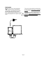
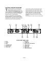
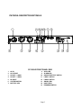
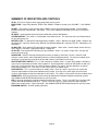
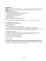
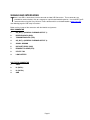
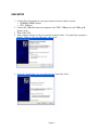
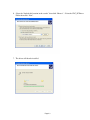
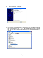
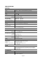
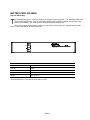
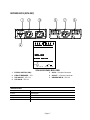
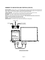
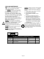
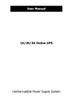
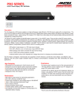
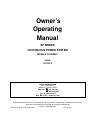
PRELIMINARY
Owner’s
Operating
Manual
SP SERIES
CONTINUOUS POWER SYSTEM
MODELS COVERED:
SP560
SP1250LE
CLARY CORPORATION
150 E. Huntington Dr.
Monrovia, California 91016
Telephone 626-359-4486
800-44 CLARY
Fax. 626-305-0254
Web HTTP: // www.clary.com
Information contained herein is the property of Clary Corporation, is proprietary, confidential, and not to be
disclosed, disseminated or used except for the purpose provided by
CLARY CORPORATION
P/N 510-16126 REV. NR -Date: 04/12
E.O. 413597
THE CONTINUOUS POWER COMPANY
TABLE OF CONTENTS
TITLE
PAGE
TABLE OF CONTENTS
2
INTRODUCTION
3
TECHNICAL DESCRIPTION
4
PACKAGING
5
PHYSICAL DESCRIPTION SP560
6
PHYSICAL DESCRIPTION SP1250LE
7
INSTALLATION
9
OPERATION
10
SIGNALS AND INTERFACING
11
USB SETUP
12
SPECIFICATIONS
15
BATTERY PACK (SP-48SB)
16
BYPASS BOX (SPH-302)
17
CARE AND MAINTENANCE
19
SERVICE AND REPAIR
20
WARRANTY
21
INTRODUCTION
C
This Owner’s Operating Manual is provided with your
new SP Series UPS. It will enhance your
understanding of the product and its functions. WE
STRONGLY URGE YOU TO READ THIS MANUAL
COMPLETELY, PRIOR TO BEGINNING
INSTALLATION OR ATTEMPTING OPERATION.
This will save you time and effort in your installation
and application, and it will assure a trouble free
installation and startup session, thus enhancing
public safety and the image of your agency.
The illustrations provided will familiarize you with this
product’s operating modes and components. Always
operate the unit within the guidelines and
specifications provided to maximize safety and the
lifetime of the unit. Also, your understanding of the
product is a key element in getting the most out of
your SP Series UPS.
ongratulations! You have selected the
highest quality protection for your continuous
power needs. This unit offers a quiet and
compact package with superior performance you can
depend on. You now own a SP Series Continuous
Power System (CPS) which is an all Digital
Technology product manufactured by Clary
Corporation, the first name in uninterruptible power
system (UPS) reliability. The Continuous Power
System is the highest order in the hierarchy of UPS
products. When power problems occur, there can
be no compromising the reliability of your power
solution. The SP Series Continuous Power System
is your complete power solution.
IMPORTANT SAFETY INSTRUCTIONS,
SAVE THESE INSTRUCTIONS
This symbol indicates that
dangerous voltage constituting
a risk of electrical shock is
present within the unit.
!
This symbol indicates that there
are important operating and
maintenance instructions in the
literature accompanying this
unit.
CAUTION
RISK OF ELECTRIC
SHOCK DO NOT OPEN
!
This manual contains important safety instructions that should be followed during installation and maintenance of
the UPS and batteries. Be aware of the following symbols and their meaning as they appear throughout the
manual:
Page 3
TECHNICAL DESCRIPTION
T
The AC utility source is connected to the power
switching and control electronics when the input
switch is closed. The input line is filtered, rectified
and power factor corrected for enhanced
performance without disturbing other equipment that
may share the same utility circuit.
The DSP processor controls an Inverter Generator
that produces a clean, low harmonic, AC output
sinewave for continuous power applications.
When the input AC utility line fails, the battery circuit
within this system takes over to ensure continuous
power. Only when properly rated input power is
returned, does the unit reconnect the input source
back to the system.
The unit is connected to a Com port which allows the
user to monitor and set operating parameters. With
a simple link to a personal computer using the
“SP560/SP1250LE UPS software program”, the user
can view the event history of the power distribution
system. More sophisticated users may choose to
implement the optional SNMP package to allow full
Network Power Management capability.
he Digital Technology-Extreme Temperature
SP560/SP1250LE Series Continuous Power
System (CPS) is a revolutionary new concept in total
power protection and management. The
SP560/SP1250LE Series is a DSP processor-based
UPS that allows the user to set most of the control
feature parameters. By directly linking a personal
computer to the SP560/SP1250LE Series Com
ports, frequency settings and operation, alarm
signals, load switching, fan operation, etc. can all be
programmed to meet specific application
requirements.
The SP560/SP1250LE Series is a true on-line,
continuous power UPS. In the tradition of Clary
products, the SP560/SP1250LE Series generates
the same high quality and proven reliability to provide
the best power protection available for today’s critical
applications.
In keeping with the state-of-the-art design, the power
electronics are completely governed by an on-board
DSP based processor. Given the powerful
processing capability of today’s DSP chips, this
allows the UPS to evolve into an all-in-one complete
power distribution and monitoring center. Not only is
your critical load insured of the most reliable and
constant power available, but the user may now
continuously monitor the status of the various
operational parameters in the system.
Page 4
PACKAGING
Y
our UPS has been carefully packaged to
withstand most abuse sustained during
shipment. The packing material has been
specifically designed to protect this system for
normal handling, using most shipping carriers. If
there is significant damage to the carton, or if there is
any physical damage to this unit, report this to your
carrier.
!
SPH-302
BYPASS-SWITCH
Page 5
These units are encapsulated in a protective wrap
that comes apart once the product is removed from
the shipping carton. Save all packing material for
future use.
The packaging also contains important information
on use and care as well as valuable warranty
information. Read all materials before storing this
literature with your other valuable product
documents.
PHYSICAL DESCRIPTION SP560
T
his section will point out and illustrate the
various indicators, functions and controls of
the SP560 and SP1250LE Series UPS. The
important attributes of the SP560/SP1250LE Series
unit are numbered to assist you in locating them on
your machine and also to fully explain its function
and how it relates to system operation.
Numbers on the drawing will correspond to the
operating component’s name at the bottom with a
brief identification. In the next section, a complete
explanation of all numbered items will be enhanced
to ensure you have a full understanding of the
visual indicators used on the front panel are long
lasting, very efficient, light emitting diodes (LED).
When operating the push-button switches, always
hold the switch in for at least two seconds to insure
function confirmation. This feature has been
implemented into the system design to avoid
inadvertent operation of any of the user-available
functions.
Pictured below is the front view of the model SP560.
SP560 FRONT PANEL VIEW
1
2
3
4
5
6
AC IN
AC OUT
DC IN
SYSTEM SWITCH
BATTERY LED
AC OUT LED
7
8
9
10
11
12
13
AC IN LED
ALARM LED
COLD START/TEST SWITCH
LOAD SWITCH
SIGNAL DB9
USB TYPE B
PROGRAM SWITCH
Page 6
PHYSICAL DESCRIPTION SP1250LE
SP1250LE FRONT PANEL VIEW
1
2
3
4
5
6
7
AC IN
AC IN FUSE
AC OUT – LOAD 1
AC OUT – LOAD 2
DC INPUT
SYSTEM SWITCH
BATTERY LED
8
9
10
11
12
13
14
15
AC IN LED
ALARM LED
COLD START/TEST SWITCH
LOAD 1 SWITCH
LOAD 2 SWITCH
SIGNAL DB9
USB TYPE B
PROGRAM SWITCH
Page 7
SUMMARY OF INDICATORS AND CONTROLS
AC IN – IEC Inlet C14 type used to supply utility power to the system.
INPUT FUSE – Input Inlet protection. SP560 - 10A, 250VAC, 5x20mm (slo-blo) fuse, SP1250LE – 15A, 250VAC,
3AG.
AC OUT – IEC Outlet C13 type used to supply 120VAC Inverter generated power provided. The SP1250LE
provides two outlets labeled Load 1 and Load 2. They can be separately controlled via the Load 1 and Load 2
switches.
DC INPUT – A two position keyed connector provided for external 48V Batteries.
SYSTEM SWITCH – This switch is used to power up or down the unit. The switch must be in the ON position to
AC or Cold start the unit.
BATTERY LED – Tri colored LED indicating battery condition. Green – Batteries are good, Yellow – Batteries are
low (below 25% capacity), Red flashing– Batteries are depleted (below 10% capacity), LED Off – No batteries are
connected.
AC OUT LED – Dual colored LED indicating AC output condition. Green solid – Inverter Output, Green flashing –
Unit in Bypass, Red solid – Output bad, LED off – Output off.
AC IN LED – Dual colored LED indicating AC input condition. Green – AC input in range, Red – AC input not
present or out of range.
ALARM LED – Red LED flashing indicating alarm active (On battery, OverTemp, Fan fail). Red LED solid
indicates a more serious alarm (Low battery warning, Inverter/Component failure). To silence an audible alarm,
quickly press and release any one of the push button switches (Cold Start/Test or Load).
COLD START/TEST SWITCH - This is a multi function push button switch. If no AC utility voltage is available, it
may still be a requirement to initialize some equipment. See the operations section for information on cold start.
Once Unit is running on AC Input, this switch becomes a Battery Test switch. See the operations section for
information on Battery Test. This switch is also used to silence an audible alarm.
LOAD SWITCH – This is a multi function push button switch. Once this switch is pressed in for at least two
seconds, output power will then be disabled to the AC Output. Pressing in this switch again for at least two
seconds, output power will then be enabled to the AC Output. This switch is also used to silence an audible alarm.
SIGNAL DB 9 - A DB-9 subminiature, female connector provided for intelligent computer monitoring systems.
See SIGNALS AND INTERFACING Section for specific pin-outs.
USB - Connector provided for intelligent computer monitoring systems. There is one USB Type A and one USB
Type B connector provided on older units. Type A is not used, Type B is used to connect to your computer.
Newer units will only have a Type B connector. See SIGNALS AND INTERFACING Section for specific pin-outs.
PROGRAM SWITCH – Used for updating firmware.
Page 8
INSTALLATION
breathing space the system has, the cooler it
operates.
☛The air should remain free from excessive dust
and chemical fumes.
Once a location has been selected and the unit is
installed, it is ready for operation.
If used as an UPS, allow at least 24 hours, after the
system is first installed, to fully charge the external
batteries to a maximum state.
The system is lightweight and can be easily moved.
Some important points to consider when positioning
a unit for operation:
☛The installation site should maintain an ambient air
o
o
temperature of less than 165 F (74 C). When the
environment for the system remains cooler during
operation, there is less stress on the batteries and
the internal electronics.
☛The air inlets, vents and fan should not be
obstructed or blocked in any way. The more
Page 9
OPERATION
O
nce the system has been properly installed, it is ready to operate. The following procedures will explain
how to start-up the system while plugged into rated electrical power and also how to start-up with no AC
power available.
Normal Operation on AC Start-Up:
• Verify that the unit is plugged into properly rated electrical power.
• Plug in External Batteries to DC input.(if used as an UPS)
• Position the System Switch to the ON position.
The system will quickly beep three times.
AC Input LED will be Green.
Battery LED should be on Green if batteries are connected.
You will now have 120VAC available at the AC outlet.
• To turn off the load, press and hold the Load Button until the AC Out LED turns off. Approx. 2 seconds.
Battery Operation after AC Start-Up:
• Unplug the unit from the standard wall outlet.
The AC IN LED will turn Red.
An Audible beep will sound.
The Alarm LED will flash Red after approx. 10 seconds.
• To silence the Audible alarm, quickly press and release either the Cold Start or Load button.
If the unit is allowed to operate further, it will time out and shut off completely. If power were to return, the unit will
automatically restart and return to the condition it was in at the moment it went into Battery Mode.
DC Start Operation (Cold Start)
If no utility power is available at the time backup power is required, the unit may be started to accomplish
abbreviated tasks. The limitations of the battery prevent extended operations at full load.
• Position the System Switch to the ON position.
• Push and hold in the COLD START switch.
You now will have 120VAC available at the AC outlet.
Loading the System
The system can be loaded up to full rated load. If too much load is applied, the audible alarm will sound. If this
increased load is not removed within a few seconds, the unit will discontinue output operation and latch into an
alarm condition. The audible alarm will continue to sound and the ALARM LED will light. Reducing the load and
cycling the System Power Switch OFF then ON can reset the system.
Page 10
SIGNALS AND INTERFACING
T
here is one DB-9, subminiature, female connector and two USB Connectors. These connectors are
provided for communications links to a computer or sophisticated monitoring device. Use the USB Type B
connector when using the Clary Universal Traffic software which can be downloaded at www.Clary.com.
See following page for USB setup instructions.
Below are the pin outs of the connectors with their default assignments:
DB9F CONNECTOR
1-
GP_OUT_1 (GENERAL PURPOSE OUTPUT 1)
2-
RECEIVING DATA (RXD)
3-
TRANSMITING DATA (TXD)
4-
GP_OUT_2 (GENERAL PURPOSE OUTPUT 2)
5-
SIGNAL GROUND
6-
DATA SET READY (DSR)
7-
REQUEST TO SEND (RTS)
8-
UTILITY FAIL
9-
LOW BATTERY
USB TYPE B CONNECTOR
1-
VBUS
2-
D- (DATA-)
3-
D+ (DATA+)
4-
GND
Page 11
USB SETUP
1. Contact Clary Corporation or your representative for latest software version.
o SP560/SP1250LE Software
o CDC_PCDriver
2. Connect the USB cable from your computer to the UPS’s USB port (use the USB type B
(Square) port).
3. Turn on the UPS.
4. Your computer will need a driver to connect for the first time. You should get a prompt as
follows: Click on “No, not at this time” then “Next”.
5. Select the “Install from a list or specific location” then click “Next”
Page 12
6. Select the “Include this location in the search:” then click “Browse”. Select the CDC_PCDriver
Folder then click “Next”.
7. The driver will then be installed.
Page 13
8.
Driver is now installed. Click “Finish”.
9. Go to your device Manager, then click on the “Ports (COM & LPT)” tab. You will see the USB
CDC serial port emulation (Com 1, 2, 3…etc.). This will be the com port assigned to your USB
port. This is the Com port you will use when connecting to the Clary Software while using the
USB port.
Page 14
SPECIFICATIONS
ELECTRICAL
Input
Voltage
120VAC
85VAC to 155VAC (without Battery discharge)
Frequency
45Hz to 65Hz
Output
Voltage
120VAC +3%
Frequency
50Hz or 60Hz +.25% (software selectable)
Current
SP560
SP1250LE
4.8 A (400W / 570VA)
10.4A (875W / 1250VA)
Crest Factor Ratio
(Non-linear load and
less than 5% THD) Typical
@50% Load
@75% Load
@100% Load
Up to 4.8:1
Up to 3.2:1
Up to 2.4:1
Harmonic Distortion
3%
Dynamic Response
+4% for 100% Step Load Change, 0.5 Millisecond Recovery Time
Overload
110% for 10 min; 200% for 50 milliseconds
Efficiency (UPS)
85%
Load Power Factor
0.7
UPS Protection
Input and Output Short Circuit; Input and Output Overload;
Excessive Battery Discharge
MECHANICAL
Input (Qty)
Output (Qty)
(1) IEC Inlet C14
SP560
SP1250LE
(1) IEC Outlet C13
(2) IEC Outlet C13
Overall Dimensions W x D x H
SP560
SP1250LE
11in x 8.5in x 1.7in
Weight
5 lb. (2.3 kg)
SP560
SP1250LE
Cooling
15.25in x 8.5in x 1.7in
8 lb. (3.6 kg)
Low Velocity, Forced Air
CONTROLS AND INDICATORS
Visual Indicators
Battery Status, AC Output, Alarm, AC Input
Controls
Load On/Off, Cold Start
Intelligent Computer Interface
(1) DB9-F – RS232/Signal Interface
(1) USB Type B
DESIGN
Standard Features
Regenerative On-Line, Sinewave Inverter Powers Load Continuously,
Extended Brownout Protection, External Battery Connector, Digitally
Controlled IGBT PWM, Power Factor Corrected on Input, Designed for
Non-linear Loads
ENVIRONMENTAL
o
o
o
o
Operating Temperature
-40 F to 165 F (-40 C to 74 C)
Humidity
0% to 95% non-condensing
Altitude
Sea Level to 10,000 Feet
Page 15
BATTERY PACK (SP-48SB)
Use with SP560 Only
T
he SP48SB battery pack is used to provide back-up power to your equipment. The SP48SB provides 48V,
2.5Ah sealed lead batteries. You can add another battery pack in parallel to provide more runtime (dual
battery cable needed). This battery pack is designed to be maintenance free.
There are also other battery options available to match the back-up time that is required for your needs.
Please Contact your dealer for more information.
SPECIFICATIONS
Voltage
48V
Capacity
2.5Ah
Runtime(Estimated)*
6 Min @ 400W, 17 min @ 200W
Overall Dimensions W x D x H
11in x 8.5in x 1.7in
Weight
10 lb. (4.5 kg)
*Estimated Runtimes are based on new batteries at 25̊C.
Page 16
BYPASS BOX (SPH-302)
H
N
G
GIN
IN
AC-OUT
H
N
G
AC-IN
SPHSPH-302
BYPASS - SWITCH
-ON
SW1
-OFF CB1-15A
UPS
AC-OUT
AC-IN
SPH-302 BYPASS BOX VIEW
1
2
3
4
BYPASS SWITCH (SW1)
CIRCUIT BREAKER – 15A
UPS AC-OUT - IEC C14
UPS AC-IN – IEC C13
5
6
7
SPECIFICATIONS
Voltage
120VAC
Current
30A in Bypass
Overall Dimensions W x D x H
5.25” x 7.50” x 1.75”
Weight
1 lb. (0.45 kg)
Page 17
AC-IN – 3 Position Connector
AC-OUT – 3 Position Connector
GENERATOR IN – IEC C14
SUMMARY OF INDICATORS AND CONTROLS (SPH-302)
BYPASS SWITCH – When switch is in the “ON” Position, bypass box AC-Out will provide inverter power from the
UPS as long as inverter power is available. If inverter power is not available, bypass power will be supplied at the
output. When in the “OFF” position, Bypass power will be supplied to the output.
CIRCUIT BREAKER – A 15A resettable circuit breaker provides protection for the UPS AC-IN line.
UPS AC-OUT – IEC Inlet C14 type connects to the AC-OUT connector of the UPS.
UPS AC-IN – IEC Outlet C13 type connects to the AC-IN connector of the UPS.
AC-IN – A 3 position connector that connects to utility input. Note: Must be connected to service with a
protection fuse/circuit breaker no greater than 30A.
AC-OUT – A 3 position connector that connects to your loads.
GENERATOR IN – IEC Outlet C13 type connects to a generator for backup power.
GENERATOR
UTILITY INPUT
LOADS
Must be provided with Circuit
Breaker no greater than 30A.
H
N
G
GENERATOR
IN
AC-OUT
H
N
G
AC-IN
SPH-302
BYPASS-SWITCH
UPS
ON SW1 OFF
CB1-15A
AC-OUT
AC-IN
AC-IN
AC-OUT
BYPASS BOX SETUP
Page 18
CARE AND MAINTENANCE
T
his device is designed to be maintenance-free.
It can be cleaned with a damp cloth or
nonabrasive cleanser.
WARNING: Do not use ACETONE-BASE
cleaning solutions. Keep cleaning solutions out of
the electrical receptacles on this device.
Be sure filters, vents and fans are kept free from
accumulation of dust, dirt or lint. Below is a simple
maintenance schedule that will assist you in keeping
the system at its peak level of performance and also
minimizing potential premature failures.
Your system contains sealed maintenance-free
batteries. When situated in the proper environment,
with the proper charging and limited cycling, these
batteries can last many years.
WARNING: Never attempt to service batteries.
High voltage exists within the unit, which could cause
electrical shock. Servicing of batteries should be
performed or supervised by personnel
knowledgeable of batteries and the required
precautions. Keep unauthorized personnel away
from batteries.
CAUTION - Do not dispose of battery or batteries
in a fire. The battery may explode.
CAUTION - Do not open or mutilate the battery or
batteries. Released electrolyte is harmful to the skin
and eyes. It may be toxic.
CAUTION
RISK OF ELECTRIC
SHOCK DO NOT OPEN
CAUTION - A battery can present a risk of electrical
shock and high short circuit current. The following
precautions should be observed when working on
batteries.
1. Remove watches, rings, or other metal objects.
2. Use tools with insulated handles.
3. Wear rubber gloves and boots.
4. Do not lay tools or metal parts on top of
batteries.
5. Disconnect the charging source prior to
connecting or disconnecting battery terminals.
6. Determine if the battery is inadvertently
grounded. If inadvertently grounded, remove
source of ground. Contact with any part of a
grounded battery can result in electrical shock.
The likelihood of such shock will be reduced if
such grounds are removed during installation
and maintenance.
The external rechargeable battery is recyclable. At
the end of its useful life, under various state and
local laws, it may be illegal to dispose of this battery
into the municipal waste stream. Check with your
local ordinances for details in your area for recycling
options or proper disposal.
!
RECOMMENDED PREVENTATIVE MAINTENANCE SCHEDULE
TIME
TASK
TOOLS REQ’D
Every 6 mo.
Test battery operation, check back-up time
None
Every 12 mo.
Thoroughly clean unit
Vacuum, brush
Every 42 mo.
Replace batteries
TBD
Every 72 mo.
Replace cooling fan
Contact Dealer
Page 19
INITIAL
SERVICE AND REPAIR
Y
our SP560/SP1250LE Series UPS is backed
by one of the finest customer service teams
available. Write or call them at any time to
obtain more information about your unit.
Clary Corporation
150 E. Huntington Dr.
Monrovia, CA 91016
1-800-551-6111
If a problem should occur, it is important that you
obtain a Return Material Authorization (RMA)
number from the Service Department to process any
unit returned to the factory. In consulting the factory,
always have the unit model number and serial
number at hand. This information is located on the
identification label and is essential in retrieving your
unit’s performance and history record.
The RMA number issued to you should appear on
the outside of the carton, if the unit is returned, or on
any correspondence regarding your unit. When
shipping a unit back to the factory, try to use the
original packing container and shipping materials.
The Service Department cannot take responsibility
for any unit damaged in return shipment. All units
must be returned prepaid to:
Clary Corporation
SP Service Center
150 E. Huntington Dr.
Monrovia, CA 91016
Page 20
WARRANTY
1.
2.
3.
TIME AND SCOPE OF WARRANTY:
1.1.
Clary Corporation hereby warrants parts shipped under this Agreement to be free from
defective workmanship for a period of 2 years following date of shipment. Accidental damage,
misuse or normal wear and tear shall not be construed as a defect.
1.2.
The date of shipment as used herein will be the date on the Bill of Lading. If no Bill of Lading
is issued the date of shipment shall be shown on seller's shipping document.
1.3.
No provision of this warranty shall cover equipment that has been altered or modified from the
original specifications to which it was manufactured unless authorized in writing.
1.4.
No provision of this warranty shall cover batteries. However, battery manufacturer's
warranties will be passed through to the customer whenever applicable.
LIMITS OF "IN WARRANTY" SERVICE LIABILITY:
2.1.
Clary is obligated during the in-warranty period to provide service and/or adjustments to
equipment returned to the factory at the expense of buyer (the term "factory" as used here-in
shall also include any field service centers which may be established by Clary) and to repair or
replace any part(s) thereof which in the opinion of authorized Clary personnel are found to
have been defective.
2.2.
Equipment requiring in-warranty services must be returned to the factory with all transportation
charges prepaid, clearly tagged, and stating the nature of the trouble experienced, and the
disposition of the equipment after repair. The equipment will be returned collect by Clary to
the location specified via the best, least expensive carrier available or via customer's shipping
instructions.
2.3.
The nature of certain equipment installations may be such that it would be impractical or
technically infeasible to remove the Clary portion of the equipment from the customer's
premises to the Clary factory. In such cases, and at the request of the buyer, Clary will
perform such service as can be satisfactorily rendered at buyer's location. The buyer will be
charged only for travel expenses incidental to the service call, provided that the warranty is
applicable.
2.4.
During the in-warranty period, no service charges shall be payable by the buyer for service
performed other than for service necessitated by accident, misuse, theft, abnormal line or
source voltage fluctuations, abnormal conditions of operation, damage by the elements or
damage resulting from adjustments, repairs, modifications made by other than Clary
Authorized personnel, or the buyer's failure to reasonably maintain the equipment.
2.5.
THE FOREGOING WARRANTY IS EXCLUSIVE AND IS GIVEN AND ACCEPTED IN LIEU
OF ANY AND ALL OTHER WARRANTIES, EXPRESSED OR IMPLIED, INCLUDING
WITHOUT LIMITATION THE IMPLIED WARRANTIES OF MERCHANTABILITY AND
FITNESS FOR A PARTICULAR PURPOSE. THE REMEDIES OF BUYER SHALL BE
LIMITED TO THOSE PROVIDED HEREIN. IN NO EVENT WILL SELLER BE LIABLE FOR
COLLATERAL OR CONSEQUENTIAL DAMAGES. No person is authorized to assume in
behalf of Clary any obligation or liability in connection with the sale, warranty or service policy
of any products manufactured and/or marketed by Clary Corporation beyond the warranty
description on the face hereof.
Clary Corporation reserves the right to make changes, additions, and/or improvements in its
products without incurring any obligation to install them on its products previously sold.
Page 21