1
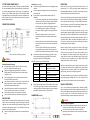
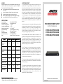
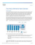
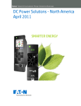
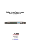
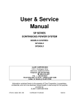
PRO SERIES
AC/DC Power Supply 1RU: 690 Watts
eliability
12V
50A
24V
25A
48V
12.5A
“DC Power Solutions…not just components”
Description
The Pro Series line of DC power supplies is a high performance, high efficiency 1RU DC power supply with no compromises. The
core of the Pro Series is derived from the state-of-the-art ICT Digital Series power supply design that delivers high efficiency, power
factor corrected AC input, space-saving 1RU chassis, FCC Class B low noise rating, and an optional battery backup terminal with
integrated low voltage disconnect.
Pro Series DC power supplies provide 690 watts of power with 12, 24 or 48VDC output. They provide an ideal DC power solution
for wireless communications professionals who demand cost effective, high efficiency space-saving DC power systems for LMR,
broadband, and network communications equipment including radios, repeaters, trunking systems, paging systems, RF amplifiers,
microwave, WiMax, routers, bridges, multiplexers, and VOIP. The Pro Series is also ideal for industrial power applications such as
security systems, transportation, process control, and DC in-building power.
} 690 watts of output power in a 1RU rack mount chassis.
} 90 to 93% efficiency over a broad power range (230VAC input).
} Wide-ranging power factor corrected AC input saves energy.
} Form C alarm and remote shutdown contacts.
} Optional battery backup with integrated low voltage disconnect for charging and protecting batteries.
The Pro Series is designed, manufactured and supported in North America to provide the most reliable, cost effective, high
efficiency 1RU DC power supply available today for wireless communications, broadband and other demanding DC power
applications.
High Reliability
} Developed and manufactured in North America by ICT
} Designed around the highest quality components available
} Every system is fully tested and burned-in at the factory
} Output bus bars allow safe and solid DC connections
} Designed to CSA, FCC Class B
Performance & Flexibility
Performance
} 690 watts of output power for demanding applications
} 90 to 93% efficiency at 230VAC input
} Power factor corrected AC input voltage range of 100-265VAC
} -20C to +60C operating temperature range
} Form C alarm contacts
} Remote shutdown signal contact
} Available battery backup option with integrated LVD
} Can operate as a DC power supply for running loads or for
dedicated battery charging
Page 1
Distribution
Pro Series power supplies are part of the next generation of
1RU high-efficiency power supplies from ICT designed with
todayʼs DC power needs in mind.
Combine the Pro Series with the ICT Distribution Series 2 to
create a cost-effective TCP/IP solution that will monitor load
conditions, AC faults, site monitoring sensors like door and
smoke alarms, and send email alerts over your Ethernet
network.
*The WƌŽƐĞƌŝĞƐϭZhǁŝƚŚŽƉƚŝŽŶĂůĚŝƐƚƌŝďƵƚŝŽŶϭZƵƉĂŶĞů
Innovative Circuit Technology Ltd.
26921 Gloucester Way, Langley, BC, Canada V4W 3Y3
Tel: 604-856-6303 | Fax: 604-856-6365 | Email: [email protected] | www.ict-power.com
800-343-000
PRO SERIES
AC/DC Power Supply 1RU: 690 Watts
iability
Mechanical
Power Specifications
Continuous Output Current - 12V
50A
Form Factor
1RU - 19” Rack Mount
Continuous Output Current - 24V
25A
Dimensions (inches) L x W x H
6.4 x 19.0 x 1.72
Continuous Output Current - 48V
12.5A
Weight
7.4 lbs
Efficiency (typical) - 12V
90%
@ 240VAC
AC Input Connectors
IEC C14 Connector
Efficiency (typical) - 24V
91%
@ 240VAC
DC Output Connectors
Busbars with 5/16” Nuts & Washers
@ 240VAC
Remote Alarm Connectors
Terminal Block (#22 to #26 AWG)
Efficiency (typical) - 48V
93%
Output Voltage - 12V
13.8VDC
Output Voltage - 24V
27.6VDC
Output Voltage - 48V
55.2VDC
Standards
Designed to UL/CSA60950, FCC Class B, CE EMC Directive
Protection Features
(Output voltage factory adjustable by specifying at time of order)
Input Voltage Range
100-264VAC
Frequency Range
50/60Hz
Power Factor (typical)
0.99
Output Ripple - 12V
20mV RMS
Output Ripple - 24V
30mV RMS
Output Ripple - 48V
60mV RMS
Line Regulation
+/- 0.1%
Load Regulation
+/- 1.0%
Over-Temperature, DC Over-Current, AC Input Voltage, DC Output Voltage,
System Fault
Warranty
Remote Communications
Form C Alarm Contacts - Normally Open, Normally Closed, Common
Remote Shutdown - 2.5 to 16 Volt Signal
Options
Output Grounding
Positive, negative or floating
o
Operating Temperature Range
Battery Backup
o
Factory-installed third terminal output for float charging
batteries. Provides automatic revert function. Includes
low voltage disconnect with factory-set disconnect and
reconnect voltage setpoints.
-20 C to +60 C
(derate
>50 oC)
Temperature Controlled Fans (side to side airflow)
LVD Disconnect Voltage
LVD Reconnect Voltage
12V
24V
48V
10.5V
12.0V
21.0V
24.0V
42.0V
48.0V
Ordering Information - All models are Configured To Order (CTO) at the factory. Options must be selected at time of ordering.
DESCRIPTION
12VDC Output
24VDC Output
48VDC Output
Pro Series Power Supply
ICT690-12S
ICT690-24S
ICT690-48S
Power supply with factory-installed battery backup terminal, automatic revert
and integrated low voltage disconnect.
ICT690-12SB
ICT690-24SB
ICT690-48SB
To find out more about the Pro Series and other DC Site Power solutions from ICT including TCP/IP Ethernet remote managed solutions,
contact our office
ICT logos and slogans © copyright Innovative Circuit Technology Ltd. Specifications subject to change without notice.
Page 2
Innovative Circuit Technology Ltd.
26921 Gloucester Way, Langley, BC, Canada V4W 3Y3
Tel: 604-856-6303 | Fax: 604-856-6365 | Email: [email protected] | www.ict-power.com
800-343-000
ICT PRO SERIES POWER SUPPLY
Pro Series power supplies from ICT provide a reliable 690 Watts
of rack-mountable dc power with optional built-in battery backup and low voltage disconnect (LVD, option “B”) capability to
power 12, 24 or 48Vdc based systems. With an efficient wide
range power factor corrected input the units are useable worldwide, and their built in rack mounting ears and bus-bar outputs
make installation simple.
CONNECTION DIAGRAM
(Shown with battery backup/LVD, option B)
WARNINGS
Risk of personal injury or damage to equipment and property!
Always observe the following:
Install and operate unit in a Restricted Access location,
such as an enclosed 19” equipment rack
Operate the supply from a grounded 3-pin 120Vac or
230Vac outlet (50 or 60Hz) with a branch circuit breaker
rated 20A or less
Use an appropriate dc over-current protection device in
line with the battery connection
Use a disconnect switch or circuit breaker in series with the
battery connection, to ensure installation and service is
done with the battery disconnected
Use wire and connectors rated for the maximum load
current and size of battery fuse or circuit breaker
Ensure battery polarity is correct before connecting
Ensure load current does not exceed max rating of unit
Installation (continued)
Connect the supply NEG bus bar to the load negative input
terminal
Connect a ground bonding wire from the chassis ground
stud to the rack
On units with the optional battery back-up and LVD
capability:
o Choose a lead-acid battery with a float voltage rating
that matches the Pro Series output voltage, and has
an Amp-hour (Ahr) capacity rating greater than 3
times the max current rating of the power supply (i.e.
use a 150Ahr battery or larger on a 50A supply)
o Connect the battery negative to the supply NEG bus
bar
o Connect the battery positive to an over current
protection device (fuse or breaker) and disconnect
switch
o With the battery fuse removed or disconnect switch
open connect the fuse or switch to the supply BAT(+)
terminal
o Either the POS or NEG lead may be connected to
earth ground, but the internal LVD contactor must
always be connected to the battery positive, as shown
Connect the remote on-off control or unit form-C alarm
contact monitoring wiring to the REMOTE connector if
needed, as shown in the following table:
REMOTE Connector: (use 22-26AWG wire)
Pin Number Name
Function
1
Shutdown (+)
Remote output shutdown,
positive (2.5-16Vdc)
2
Shutdown (-)
Remote output shutdown,
return
3
NC
Alarm NC (alarm state)
4
NO
Alarm NO (alarm state)
5
Common
Alarm output common
Plug an approved AC power cord set rated for 10A or more
into the IEC type AC input connector on the back panel of
the supply (120V cord included with unit), then plug into a
grounded 3 terminal 120Vac or 230Vac outlet
DIMENSIONS (inches)
OPERATION
Switch on the unit using the front panel power switch, and
observe that it is lit. Verify the supply output voltage using a
hand held digital voltmeter. If a battery is connected install the
external fuse and close the disconnect switch.
On units with the battery back-up option connected switch off
the ac power, and verify that the battery voltage is provided to
the output load terminal using a hand held digital voltmeter.
Switch AC back on, and verify the output supply voltage rises to
the normal output rating as the battery charges.
The unit can now be left operating normally. As long as the
external back-up battery voltage is greater than the low voltage
disconnect (LVD) level the battery will be connected directly to
the supply output and will instantly power the load in case of an
AC power failure. When the battery voltage drops below the
LVD level the internal relay will open, preventing the battery
from being excessively discharged.
When AC power returns the supply will initially trickle charge
the battery until its voltage rises to the re-connect level, and it
will then close the internal LVD relay, and the battery will be
fully charged to the power supply output voltage level with
charge current limited to the maximum supply output rating.
The battery will be maintained at the supply output (float)
voltage level until AC power is removed.
Batteries connected directly to the supply output (not using the
LVD option BAT terminal) will be charged to the supply output
voltage level with a current limited to the maximum supply
output rating, with no initial trickle charge mode.
The remote shutdown input may be used to disable the supply
output by applying a voltage from 2.5 to 16V, and the form-C
alarm contacts can be used to monitor for fault conditions.
PARALLEL OPERATION
Up to 3 units without the optional battery backup capability
may be connected in parallel to power higher current loads. The
unit with the highest output voltage will initially provide most of
the load current, but as load current increases the current
supplied will tend to balance between the parallel units.
INSTALLATION
Mount the unit in a standard 19 inch equipment rack, (ensuring
side air vents are not blocked) using rack mounting screws (not
supplied), then make the following connections using wire and
connectors appropriately rated for the maximum input and
output current rating of the unit:
Connect the supply POS output bus bar to the load positive
input
CAUTION
Risk of damage to equipment!
Ensure current supplied through the optional internal LVD
contactor cannot exceed the current rating of the unit
Do not use the internal LVD contactor for parallel
applications where load current can exceed the maximum
rating of a single unit
ALARMS
LIMITED WARRANTY
Internal protection circuitry will disable the supply output, and
cause the form-C alarm relay contacts to go to the NO/NC
alarm state for the following conditions:
Internal temperature too high (will automatically reset
when cool)
Input ac voltage out of range (resets when in range)
Output voltage too high (cycle power to reset)
Battery voltage too high (resets when voltage in range)
Internal System Fail (resets if internal fault clears)
ICT Ltd. warrants to the original consumer purchaser that this
product shall be in good working order, free from defects in
materials and workmanship, for a period of three (3) years from
the date of purchase. Should failure occur during the above
stated time period, then ICT will, at its option, repair or replace
this product at no additional charge except as set forth below.
All parts, whether for repair or replacement, will be furnished
on an exchange basis. All exchange pieces become the property
of ICT. This limited warranty shall not apply if the ICT product
has been damaged by unreasonable use, accident, negligence,
disaster, service, or modification by anyone other than the ICT
factory.
SPECIFICATIONS
Input Voltage:
Input Power Factor:
V-output Line Regulation:
V-output Load Regulation:
Operating Temperature:
Output Grounding:
Efficiency:
Remote Shutdown:
Form-C Alarm relay:
EMC:
Model:
ICT690-12
ICT690-24
ICT690-48
Output Voltage
(Nominal, +/0.5%)
13.8V
27.6V
55.2V
Output Current
Limit (min-max)
50.0 – 52.5A
25.0 –
26.25A
12.5 – 13.1A
Output V Noise
(max)
20 mVrms
30 mVrms
60mVrms
Input Current
max at 100Vin
9A
9A
9A
Max Voltage for
full current out
13.8V
27.6V
55.2V
LVD Disconnect
point (+/- 2%)1
10.5
21.0
42.0
LVD Reconnect
point (+/-2%)1
12.0
24.0
48.0
690W
690W
690W
Output Power
(max rated)
1
2
100 – 264Vac 50/60Hz
0.99 (120Vac input)
+/- 0.1%
+/- 1%
-20°C to 60°C2
Positive, Negative or floating
88% typical (120Vac)
2.5 to 16V signal
0.5A 125Vac/dc max
Meets FCC part 15 class B limits
With LVD Option installed, factory default levels shown.
Reduce output current 10% for ambient above 50C
Limited warranty service is obtained by delivering the product
during the above stated three (3) years warranty period to an
authorized ICT dealer or ICT factory and providing proof of
purchase date. If this product is delivered by mail, you will
insure the product or assume risk of loss or damage in transit,
and prepay shipping charges to the factory.
Every reasonable effort has been made to ensure that ICT
product manuals and promotional materials accurately describe
ICT product specifications and capabilities at the time of
publication. However, because of ongoing improvements and
updating of ICT products, ICT cannot guarantee the accuracy of
printed materials after the date of publication and disclaims
liability for changes, errors or omissions.
PRO SERIES POWER SUPPLY
INSTRUCTION MANUAL
ICT690-12S/ICT690-12SB
ICT690-24S/ICT690-24SB
ICT690-48S/ICT690-48SB
If this ICT product is not in good working order, as outlined in
the above warranty, your sole remedy shall be repair or
replacement as provided above. In no event will ICT be liable for
any damages resulting from the use of or the inability to use the
ICT product, even if an ICT employee or an authorized ICT
dealer has been advised of the possibility of such damages, or
for any claim by any other party.
ICT reserves the right to make changes without further notice to
any products or documentation for improvement of reliability,
function, or design.
ICT Ltd. does not recommend use of its products in life support
applications wherein a failure or malfunction of the product
may directly or indirectly threaten life or cause injury. The user
of ICT products, which are to be used in life support applications
as described above, assumes all risks of such use and
indemnifies ICT against all damages.
INNOVATIVE CIRCUIT TECHNOLOGY LTD.
855-343-000