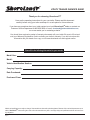
1
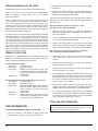
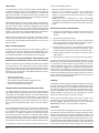
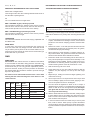
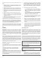
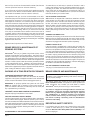
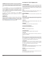
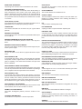
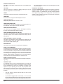
UTILITY TRAILER OWNER’S GUIDE
Thank you for choosing ShoreLand’r®!
Here are the operating instructions for your new trailer. Please read this document
carefully before using your trailer and keep it in a safe place for future reference.
If you have any questions about your trailer contact your local ShoreLand’r® dealer or contact our
Customer Service Department at 800-859-3028 or e-mail: [email protected],
so we can assist you in contacting a dealer.
You should have recieved a packet of warranty documents with your trailer. Be sure to fill out and
mail your Warranty Registration Card to activate your trailer’s warranty. If you did not recieve this
information ask your dealer for a copy or visit www.shorelandr.com and register online.
Please fill in the following information for your records
Model Year:
Model:
Vehicle Identification Number:
Carrying Capacity:
Date Purchased:
Purchased From:
Models and specifications are subject to change. Some models are shown with optional equipment. Because of the continual improvements to our
trailers, ShoreLand’r® reserves the right to add or discontinue models at any time or to change design and specifications without notice and incurring obligations.
Midwest Industries, Inc.
Page 1
Ida Grove, IA 51445
800.859.3028
www.shorelandr.com
0003513
Table of Contents
Information on Passenger Vehicle Tires .................. 8
UTQGS (Uniform Tire Quality Grading System) Info...... 8-9
Torquing Procedure For Mounting Wheels .............. 9
Rim................................................................................. 9-10
Brakes ............................................................................ 10
Glossary of Tire Terminology ......................................... 13-15
Specifications & General Information
®
Matching Your ShoreLand’r to Load Hauling ............. 2
Load Carrying Capacity ................................................. 3
Weight Distribution / Tongue Weight .............................. 3
Tow Vehicles .................................................................. 3
Trailer Balls and Coupler ............................................... 4-5
Safety Chains ................................................................ 5
Proper Winch Post Adjustment ...................................... 6
Bow Eye Safety Chain ................................................... 6
Winch Handles ............................................................... 6
Bow Pulpits and Winch Post Lengths ............................ 6
Wiring Diagram and Color Code .................................... 6
Tire Information .............................................................. 6-11
Determining Correct Load Limits ............................. 6
Tire Safety ................................................................ 7
Basic Tire Maintenance ........................................... 7
Recommended PSI & Maximum Load Capacity ...... 7
Understanding Tire Pressure & Load Limits ............ 7
Maintaining Proper Tire Pressure ............................ 7
Tire Size ................................................................... 7
Tire Tread ................................................................. 7-8
Tire Balance and Wheel Alignment .......................... 8
Tire Repair ............................................................... 8
Tire Fundamentals ................................................... 8
You and Your ShoreLand’r®
®
We at ShoreLand’r would like to thank you for purchasing one
of our trailers!
Our goal is your complete satisfaction, that is why we recommend
leading this manual in its entirety. A better understanding of your
trailer’s features, regulations and adjustments will make your towing experience more pleasurable.
It is important that you give your new trailer proper care and maintenance to ensure that it continues to provide the dependable performance year after year.
Happy trailering!
Toubleshooting & Maintenance
Lighting .......................................................................... 10
Paint and Its Care .......................................................... 10
Repacking Bearings ....................................................... 10-11
Hubs, Bearings, Races & Seals Chart ........................... 11
Grease Seals ................................................................. 11
Recommended Lubricant ............................................... 11
Bearing Repacking ........................................................ 11
Bearing Adjustment ....................................................... 11-12
Brakes Service & Maintenance ...................................... 12
Backing Up Trailer With Disc Brakes ............................. 12
Reporting Safety Defects ............................................... 12-13
Warranty Information ..................................................... 13
IMPORTANT: Read this manual carefully with special attention
directed toward all WARNING, CAUTION and IMPORTANT
information.
Because of the continual improvements being made in our line,
ShoreLand’r® reserves the right to add or discontinue models at
any time or to change design and specifications without notice and
incurring obligations.
All specifications contained herein were in effect at the time this
manual was printed.
Should a problem arise, please contact the dealer from whom the
original purchase was made. You may also call our distributor for
your area or call our Customer Service Department by phone at
800-859-3028 or e-mail [email protected].
NOTICE
This trailer is equipped to meet applicable U.S. Federal safety standards. Check local and state requirements regarding brakes and any additional
equipment that my be required. Any modifications or additions including load equalizing hitches, without written factory consent; usage in an abnormal
manner including overloading voids all manufacturers warranties and liability.
Referencing the Utility Trailer in this Manual
All references to the trailer or component parts to either left or right are made with the assumption that you are standing behind the trailer
facing forward. Your left-hand or right-hand is the equivalent on the trailer.
Matching Your Shoreland’r® to the Load You Intend to Haul
The key to carefree trailering is purchasing a trailer that is designed with a carrying capacity large enough to carry the loads you intend to
haul on it. This includes all excess gear and tie down materials used to contain the load on the trailer when towing.
The trailer should also be long enough to properly support the materials you are hauling. It must also be of sufficient width to offer stability
while towing.
Midwest Industries, Inc.
Page 2
Ida Grove, IA 51445
800.859.3028
www.shorelandr.com
0003513
Load-carrying Capacity
Located on the front left-hand side of the frame, (either the inside
or the outside) is the VIN (Vehicle Identification Number) tag. It will
show the GVWR (Gross Vehicle Weight Rating) which is the maximum load that can be applied to the tires on the trailer. Note that
the VIN tag may have as many as three different GVWR ratings
listed because some trailers frames have more than one tire option
available. The GVWR and the carrying capacity of the trailer may
vary based on the tire size installed on the trailer.
Also listed on the VIN tag is the carrying capacity of the trailer.
This is the maximum carrying capacity of the trailer with its respective tire option. It may not necessarily equal the total GVWR of the
trailer less the empty weight of the trailer because there may be
another controlling factor such as frame strength that reduces the
carrying capacity to what is listed on the VIN tag.
The tire label will list the size tire that was installed on the trailer as
original equipment when it was sold to you, the consumer. It also
lists the maximum carrying capacity of the trailer.
IMPORTANT
The total weight of the load must never exceed the weight of cargo
listed on the tire label and/or the maximum load carrying capacity
listed on the VIN tag on your trailer. The GVWR (Gross Vehicle
Proper Weight Distribution & Tongue Weight
Ensuring that your trailer has the proper GVWR is very important.
Once that has been established and you have the load on the trailer
it is equally important that you have proper weight distribution.
Tongue Weight
The tongue weight on your trailer should range from 5-10% of the
total weight of the trailer and all the cargo that it is carrying. This
is the amount of weight that is then transferred to the tow vehicle
through the ball hitch. Smaller trailers should have a tongue weight
that ranges closer to the 10% while larger trailers will tend to be
closer to the 5% range. This should be checked when the tongue
is parallel to the ground. A bathroom scale can be used to help
determine the tongue weight as long as the above conditions are
adhered to.
Weight Rating) listed is the maximum total weight of the trailer with
accessories and all cargo allowable to be carried on the tires that
are installed on the trailer.
Some model trailers have a different limiting factor other than the
tires, example frame, or brake law limitations. The maximum load
carrying capacity that is listed should never be exceeded.
CAUTION: The maximum load applied to the trailer
must never exceed the carrying capacity of the trailer
as stated on the VIN label and/or the tire placard. Doing
so may cause failure of one or more component parts of
the trailer causing potential damage to the trailer and/
or a potential accident. All concentrated loads must be
spread over as large an area as possible to eliminate
potential damage to the decking.
Shown below is an example of the VIN and tire label that is placed
on your trailer showing the items just discussed above. Once you
have familiarized yourself with the information supplied on the example tire label and VIN tag, check the tire size and capacity of
your trailer as shown on the VIN tag on your trailer.
from side to side) as you travel down the highway. This creates
excessive strains on the tow vehicle, hitch and also the trailer itself.
It can very easily lead to an accident.
To adjust for too light tongue weight the load must be shifted forward with respect to the axle. This will increase the weight that is
transferred to the tongue. Adjustments should be made until the
tongue weight falls within the 5% and 10% recommended range.
Likewise, if you have too much tongue weight adjust the weight
backwards with respect to the axle until the tongue weight falls in
the recommended range.
Tow vehicles vary on how much tongue weight they can support for
proper towing.
Example: The total weight of the trailer with load is 2,000 pounds.
The tongue weight should not be less than 100 pounds (5%) nor
more than 200 pounds (10%). A reasonable tongue weight for a
trailer this size is 125-150 pounds.
Too light of tongue weight can cause the trailer to “fishtail” (sway
Midwest Industries, Inc.
Page 3
Ida Grove, IA 51445
800.859.3028
www.shorelandr.com
0003513
IMPORTANT: Before towing this trailer be sure to read the
instructions and warnings supplied in this manual. Also read
the information supplied with your tow vehicle so you know
and understand it’s limitations.
NEVER TOW THIS TRAILER BEFORE CHECKING:
•
•
•
•
•
•
•
•
•
•
•
Coupler and latch assembly show no signs of wear or damage.
Coupler hitch and hitch ball are of the same size.
Coupler and safety chains are safely secured to the hitch.
Check all fasteners for proper tightness.
Load is securely tied down to the trailer.
Wheel lug nuts are properly tightened to the right torque.
Wheel bearings are properly adjusted and maintained.
Load is within the maximum load carrying capacity of trailer.
Tires are properly inflated and are road worthy.
All trailer lighting is working properly.
Trailer brakes are properly adjusted and in working condition.
IMPORTANT: The load must be distributed equally on the
bed of the trailer if possible. Heavy, concentrated loads may
cause damage or possible failure of the trailer decking. If
concentrated loads are placed on the trailer deck, spread the
load over a larger area by placing a larger size steel plate or
multiple layers of plywood on the trailer decking before placing on the concentrated load.
WARNING: Loads placed on the trailer must be securely
tied to the trailer frame or decking. Always use appropriate
tie downs designed to restrict loads from moving when properly attached. Failure to do so will allow shifting of the load
causing potential trailer failure and/or loss of the load and
personal injury.
It is also important that the lighting system in the tow vehicle has
sufficient capacity to support the additional load the trailer lighting
will add to the system. A heavy duty flasher may be required to
make your turn signals function properly.
TRAILER BALLS & COUPLERS
WARNING: Failure to properly engage the hitch ball in the
coupler ball socket and securely lock the coupler latch mechanism can cause the trailer to become detached from the
tow vehicle while traveling, which may cause serious injury
or property damage.
Trailer couplers shall be permanently marked with (A) Coupler
manufacturer name, initials, or trademark, (B) Part, style or model
number, (C) SAE coupler designation and gross trailer weight, (D)
Ball diameter for which rating (GVWR) shall not exceed the gross
trailer weight marked on the trailer coupler.
The hitch balls have the rated load they are capable of towing
stamped into the top of the ball.
Make sure the ball that you use to tow your trailer has the
same capacity rating as the coupler.
Do not use a different size ball than the size the coupler is
designed to use.
Class
II
III
Coupler
3,500# GVWR
5,000# GVWR
Ball Diameter
2”
2”
This trailer is equipped to meet all applicable federal safety
standards in effect the day of manufacture. Check local and
state requirements regarding brakes and any additional equipment that may be required.
Check regulations on maximum trailer width in the states you
plan to tow your trailer.
The addition of optional equipment to your trailer may increase the total weight of your trailer package to where it now
exceeds the maximum load carrying capacity of the trailer.
TOW VEHICLES
WARNING: Serious injury or property damage can result if
the total weight of your loaded trailer exceeds the capacity of
the hitch and/or your tow vehicle.
It is very important that you know and understand the towing capabilities of your tow vehicle. This is especially true with the braking
abilities of the tow vehicle. You should check with your authorized
dealer to see what the capabilities are for the total towing load and
the maximum allowable tongue weight for the vehicle you plan on
using for towing. Several options are available for these cars or
pickups which will help your towing ability. They include transmission coolers, engine oil coolers, proper rear end ratios, air shocks,
over-size tires, and also heavy duty radiators. Many can be purchased with the optional trailer package that includes some or all of
the above mentioned items.
Midwest Industries, Inc.
Page 4
Ida Grove, IA 51445
To adjust your Class II and Class III coupler to your trailer ball, remove the coupler from the ball. Reach under the coupler and raise
the channel lock up so the nut can be turned. Turn the adjusting nut
clockwise to tighten the ball clamp grip on the ball, counterclockwise to loosen ball clamp grip on the ball. Once the nut has been
adjusted make sure the channel lock has positioned back down
around the flat surfaces of the nut so it is locked from turning. Replace the hitch back on the ball and latch. Repeat this process until
the ball clamp latches securely around the ball.
HITCH COUPLER TROUBLESHOOTING
If the coupler becomes damaged it must be repaired or replaced
before towing. When the coupler is placed on the ball, the latch
should close firmly. Keep the latch mechanism lightly oiled and
clean. Items to check for are as follows:
1. Latch does not grasp ball securely:
A. Check the ball size. Make sure the ball and coupler are
the same size.
B. Unlatch the mechanism and reach under the ball clamp.
Raise the retainer clip that keeps the nut from turning,
800.859.3028
www.shorelandr.com
0003513
then turn the adjustment nut clockwise to tighten
the grip on the ball. Make sure the nut returns to its proper
position in the retainer clip, then latch the hitch on the ball.
If it is still loose repeat the process until the grasp on the
ball is right.
2.
Latch does not snap into full latch position:
A. Check adjustment. Latch mechanism may be to tight.
Loosen by reversing procedure in step #l and turning the nut
counterclockwise.
B. Check to see that the coupler housing has not been
damaged, keeping the ball hitch from fitting completely into the
housing as designed.
3.
Keep the tongue blocked up when not in use so the coupler
and mechanism are not in the ground being exposed to dirt
and moisture.
4.
Apply a small amount of an automotive grease to the ball
before hitching coupler to prevent wear of the two parts during
towing.
5.
Make sure the latch safety pin is in position before towing.
COUPLER & BALL ENGAGEMENT
If the coupler and towing ball resist attempts to make engagement,
do not force latch assembly. Instead, check the ball diameter to
verify that it conforms to Society of Automotive Engineers (SAE)
specifications. Standard two-inch diameter ball should be within
the limits of 2.000-inches to 1.970-inches. Balls larger than 2.000inches will not readily fit the coupler. A two-piece coupler ball is not
recommended.
If the coupler becomes damaged it must be repaired or replaced
before towing. When the coupler is placed on the ball, the latch
should close firmly. Keep the latch mechanism lightly oiled and
clean.
Improper engagement of the coupler and ball can cause damage if
the vehicles separate in transit: thus, caution must be exercised to
insure a secure hook-up. Lower the coupler onto the ball with the
coupler latch in the vertical position. Continue to lower the trailer
tongue until the jack clears the ground, then flip the coupler latch
to its locked (horizontal) position. At this point visually observe that
the ball is fully engaged in the ball hitch. An even better check to
make sure the two are fully engaged is to raise the tongue of the
trailer again using the jack. Raise until the ball hitch connection
starts to raise the rear of the tow vehicle. If the connection was not
properly made, the ball and socket will separate as the tongue of
the trailer is raised.
WARNING: Failure to properly attach safety chains between
the trailer and tow vehicle can result in a run away trailer.
WARNING: Before trailering to avoid accidents...
•
Hitch only to ball size marked on coupling.
•
Ball clamp must capture ball and lever or handwheel
is fully clamped.
•
Cross safety chains under coupling.
•
Allow only enough slack for turns.
Bottom View Shown
The safety chains on your trailer are an added insurance that it
will not become detached from the tow vehicle. ShoreLand’r®
provides all safety chains with an added clasp to keep them
from becoming accidentally detached from the tow vehicle.
Your trailer hitch on the tow vehicle should have two attaching holes or rings for attaching the safety chains, preferably one
on each side of the ball hitch. Crisscross the chains under the
tongue, the chain on the left side of the trailer tongue attached
to the right side of the ball hitch, the chain on the right side of
the trailer tongue attached to the left side of the ball hitch.
This prevents the trailer tongue from dropping to the road should
the coupler or ball hitch fail. The chains should be rigged as tight as
possible with just enough slack to allow tight turns to be made. This
can be accomplished by twisting the chain hook in a clockwise or
counterclockwise direction thus twisting the link spacing and making the chain shorter. Also by keeping your chains as short as possible you prevent them from dragging on the road and wearing the
chain links.
If for any reason you find it necessary to replace a safety chain, use
only original equipment.
SAFETY CHAINS
Listed in the chart below are the different class sizes of safety chains
and the rated load each chain must be capable of withstanding.
TRAILER
CLASS
TRAILER WEIGHT
GVWR IN LBS.
MINIMUM BRAKING
STRENGTH IN LBS.
I
II
III
to 2,000
2,000 to 3,500
3,500 to 5,000
2,000
3,500
5,000
Midwest Industries, Inc.
Page 5
Ida Grove, IA 51445
800.859.3028
www.shorelandr.com
0003513
WIRING DIAGRAM & COLOR CODE
All trailer lights must be in proper working order before towing.
There are two basic wire harness plugs that ShoreLand’r®
uses for plugging the trailer lighting into the tow vehicle.
They are as follows:
A flat four plug that is used on either all trailers without brakes or
else on trailers that are equipped with drum brakes. This plug is
used in these applications because the only thing needing to be
connected to the tow vehicle are lights. A solenoid lock out system
is not required to operate drum brakes. The drum brakes have a
mechanism in them that prevents the brake shoes from contacting
the drums when the trailer is backed up.
The flat five plug is used on all trailers equipped with disc brakes.
Disc brakes operate as well in reverse as they do going forward.
This results in the trailer not being able to be backed up without the
use of a solenoid to block the brake fluid from activating the brakes.
The solenoid is activated by the extra blue wire in the flat five plug
that is attached to the backup lights of the tow vehicle. When the
tow vehicle is placed in reverse, the backup lights are activated
which then activates the solenoid diverting the brake fluid generated by the actuator back into the actuator reservoir causing the
brakes not to function in reverse.
WIRING COLOR CODE
The wiring in your ShoreLand’r® is color coded as per wiring specifications. The following colored wires are connected to the proper
lights to perform the required functions as listed:
Flat Four Wire Harness Plug
Yellow Wire ......... Left Stop and Turn
Green Wire ......... Right Stop and Turn
Brown Wire ......... Taillights, Rear Side Marker Lights, Front
........................... and Rear Side Marker Lights, Rear Clear........................... ance Lights Including the Three-Light Rear
........................... Clearance Bar
White Wire .......... Ground Wire
Flat Five Wire Harness Plug (For Disc Brake Trailers Only)
Yellow Wire ......... Left Stop and Turn
Green Wire ......... Right Stop and Turn
Brown Wire ......... Taillights, Rear Side Marker Lights, Front and
........................... Rear Side Marker Lights, Rear Clearance
........................... Lights Including the Three-Light Rear
........................... Clearance Bar
White Wire .......... Ground Wire
Blue Wire ............ Brake Solenoid that is mounted to the rear
........................... of the actuator to disengage the disc brakes
........................... on the trailer so it can be backed up.
• This figure equals the available amount of cargo and luggage
load capacity.
• Determine the combined weight of luggage and cargo being
loaded on the vehicle. That weight may not safely exceed the
available cargo and luggage load capacity.
The trailer’s placard refers to the Tire Information Placard attached
adjacent to or near the trailer’s VIN (Certification) label at the left
front of the trailer.
Steps for Determining Correct Load Limit – Trailer
(For Trailers Over 10,000 lbs. GVWR):
1.
Determine the empty weight of your trailer by weighing the
trailer using a public scale or other means. This step does not
have to be repeated.
2.
Locate the GVWR (Gross Vehicle Weight Rating) of the trailer
on your trailer’s VIN (Certification ) label.
3.
Subtract the empty weight of your trailer from the GVWR
stated on the VIN label. That weight is the maximum available
cargo capacity of the trailer, and may not be safely exceeded.
Steps for Determining Correct Load Limit – Tow Vehicle
(For Tow Vehicles 10,000 lbs. GVWR or Less):
1.
Locate the statement, “The combined weight of occupants and
cargo should never exceed xxx lbs.,” on your vehicle’s
placard.
2.
Determine the combined weight of the driver and passengers
who will be riding in your vehicle.
3.
Subtract the combined weight of the driver and passengers
from xxx kilograms or xxx pounds.
4.
The resulting figure equals the available amount of cargo and
luggage capacity. For example, if the “xxx” amount equals 1400
lbs. and there will be five 150 lb. passengers in your vehicle,
the amount of available cargo and luggage capacity is 650 lb.
(1400 – 750 (5 x 150) = 650 lbs.)
5.
Determine the combined weight of luggage and cargo being
loaded on the vehicle. That weight may not safely exceed the
available cargo and luggage capacity calculated in Step # 4.
6.
If your vehicle will be towing a trailer, load from your trailer will
be transferred to your vehicle. Consult the tow vehicle’s manual
to determine how this weight transfer reduces the available
cargo and luggage capacity of your vehicle.
TIRES AND TIRE PRESSURES
TIRE INFORMATION
WARNING: Keep tires properly inflated. Failure to maintain correct tire pressure may result in tire failure and loss of control
resulting in serious injury or property damage.
STEPS FOR DETERMINING CORRECT LOAD LIMIT
• Locate the statement “The weight of cargo should never
exceed XXX kg or XXX lbs.” on your vehicle’s placard.
Midwest Industries, Inc.
Page 6
Ida Grove, IA 51445
800.859.3028
www.shorelandr.com
0003513
TIRE SAFETY
month for the following reasons:
The most common cause of trailer tire failure is under-inflation. It
is important, therefore, that you always maintain the specified air
pressure, as indicated by the tire manufacturer on the tire’s side
walls. This information can also be found on the tire label or the
manufacturers certification label. Most tire manufacturer’s have the
air pressure molded on the tire side wall.
• Most tires will naturally lose air over time.
• Tires can lose air suddenly if driven over an object that
punctures or cuts the tire. Sometimes a sharp blow from a
pothole or curb can knock the tire loose from the rim causing
immediate deflation.
• Radial tires have an appearance of being under-inflated
because of the design and a visual inspection will not always tell
you whether the air pressure inside is below its proper operating
range.
Maintaining proper tire pressure, observing all tire and trailer maximum carrying capacities, avoiding road hazards, and inspecting
the tires for cuts, slashes and other irregularities are the most
important things you can do to avoid tire failure. These practices,
along with other care and maintenance, can improve handling, help
protect you and others from avoidable breakdowns and accidents,
improve fuel economy, and increase the life of your tires.
MAINTAINING PROPER TIRE PRESSURE
1.
Locate the recommended tire pressure on the trailer’s tire
information placard, certification label or else in the owner’s
manual.
2.
Record the tire pressure of all tires.
3.
BASIC TIRE MAINTENANCE
If the tire pressure is too high in any of the tires, slowly release
air by gently pressing on the tire valve stem with the edge of
your tire gauge until you get the correct pressure.
4.
Properly maintained tires improve the load-carrying capability of
your trailer. You can help avoid flat tires and tire failures by maintaining proper tire pressure, observing tire and trailer capacity limits, avoiding road hazards, and inspecting your tires regularly.
If the tire pressure is too low, note the difference between the
measured tire pressure and the correct tire pressure. These
“missing” pounds of pressure are what you will need to add.
5.
Add the missing pounds of air pressure to each tire that is
under inflated.
6.
Check all tires to make sure they have the same air pressure.
Make tire safety a regular part of your trailer maintenance routine.
The time you spend is minimal compared to the amount of time,
inconvenience, and potential safety hazards that can occur from a
flat tire or failure.
IDENTIFYING YOUR RECOMMENDED TIRE PRESSURE AND
MAXIMUM LOAD CARRYING CAPACITY FOR YOUR TRAILER
Both the tire placard and the VIN label are permanently attached
to the side frame of your trailer and have the required information printed on them. They also list the maximum load that can be
placed on the trailer without exceeding the load limits of the tires or
the trailers other components. These labels indicate the manufacturers information including:
•
•
•
•
•
Recommended tire size
Recommended tire inflation pressure
The maximum weight the trailer is designed to carry
Gross vehicle weight rating of the trailer
Gross axle weight rating of the trailer
TIRE SIZE
UNDERSTANDING TIRE PRESSURE AND LOAD LIMITS
Tire inflation pressure is the level of air in the tire that provides it
with the load-carrying capacity and affects the overall performance
of the trailer. The tire inflation pressure is a number that indicates
the amount of air pressure that is inside the tire. It is measured in
pounds per square inch (PSI). The tire must be inflated to the air
pressure as designated on the labels. Also listed on the labels is
the air pressure in kilopascals (kPa), which is a metric measurement.
Tire manufacturers determine the air pressure to maximize the
amount of weight the tires can safely carry. The proper tire pressure
for your trailer tires is referred to as the “recommended cold inflation pressure.” It is difficult to obtain the recommended tire pressure if your tires are not cold when the reading is taken because
the air will expand when it is warmed by towing down the road, thus
increasing the air pressure inside. If air is added to a tire that is low
the air pressure should never exceed the recommended pressure.
It is important to check your trailer’s tire pressure at least once a
Midwest Industries, Inc.
Page 7
Ida Grove, IA 51445
If you have been towing your trailer and think that a tire is under
inflated, fill it to the recommended cold inflation pressure indicated
on your trailer’s tire label placard or the VIN label. You can also
check the sidewall of the tire for a correct tire inflation pressure.
Your tire will have a slightly lower air pressure because the tire is
warm when you are inflating it, but it will be much better than to
continue to tow it with the under inflation it may have had. Once the
trailer has been parked long enough to allow the tires to cool down,
recheck the tire pressure and add additional air to return the tire
pressure to the recommended level.
To maintain the trailer’s carrying capacity and safety, purchase only
the same size tires as what were originally supplied on the trailer.
The tires on the trailer are an ST rated tire. This means that they
are a Special Trailer service tire that has more load carrying capacity than a comparable size tire automotive grade tire. The carrying
capacity molded on the side wall of an automotive tire must be
reduced by 10% if it is going to be used on a trailer.
Look at the tire information placard, the owner’s manual, or the
side wall of the tire you are replacing to find this information. If you
have any questions about the correct size to choose, consult your
ShoreLandr’s® dealer or local tire dealer for assistance.
TIRE TREAD
The tire tread provides a gripping action to the road to prevent it
from sliding on the road surface when cornering and also to help in
braking in the event that your trailer is equipped with brakes. Tires
are not as safe when the tire tread is worn down to less than 1/16
inch tread. This is easily identified because most tires are manufactured with tread, wear indicators that let you know when the tires
are worn to the point they should be replaced. These indicators are
raised sections spaced intermittently in the bottom of the grooves.
800.859.3028
www.shorelandr.com
0003513
When the tread has worn down to the point that they appear to
be even with the outside of the tread it is time to replace the tire.
Another method for checking tread depth is to place a penny in the
tread with Lincoln’s head upside down and facing you. If you can
see the top of Lincoln’s head, you are ready for new tires.
TIRE BALANCE AND WHEEL ALIGNMENT
To avoid vibration or shaking of the trailer when it is towed, the
tires must be properly balanced. Unbalanced tires, when rotate,
will cause vibration. The more they are out of balance, the more
the vibration will be. This vibration can be eliminated by positioning
weights on the wheel to counterbalance heavy spots on the wheel
and tire assembly. Most any tire store or service station that deals
with tires has the capability of balancing tires.
The wheels must be aligned so they are rotating in the same plane
as what the trailer is being towed. They must be positioned so that
they rotate in the same line as the trailer rather than at some slight
angle either inward or outward from this line. If they are not aligned
correctly, they will have a tendency to skid down the road causing the tread to wear off quickly and crooked. Correct alignment
maximizes the life of your tires and are preset when the axles are
welded during manufacturing. This alignment is correct and will
remain correct when towed under most towing conditions. Hitting
curbs and large pot holes with the trailer tires may distort the axle
and cause the spindle position to be knocked out of alignment.
NEXT NUMBER
This three-digit number gives the width in millimeters of the tire
from side wall edge to side wall edge. In general, the larger the
number, the wider the tire.
NEXT NUMBER
This two-digit number, known as the aspect ratio, gives the tire’s
ratio of height to width. Numbers of 70 or lower indicate a short side
wall for improved steering response and better overall handling on
dry pavement.
R
The “R” stands for radial. Radial ply construction of tires has been
the industry standard for the past 20 years. A “D” stands for bias
ply construction.
NEXT NUMBER
This two-digit number is the wheel or rim diameter in inches. If you
change your wheel size, you will have to purchase new tires to
match the new wheel diameter.
TIRE REPAIR
U.S. DOT TIRE IDENTIFICTION NUMBER
This begins with the letters “DOT” and indicates that the tire meets
all federal standards. The next two numbers or letters are the
plant code where it was manufactured, and the last four numbers
represent the week and year the tire was built. For example, the
numbers 3197 means the 31st. week of 1997. The other numbers
are marketing codes used at the manufacturer’s discretion. This
information is used to contact consumers if a tire defect requires
a recall.
The proper repair of a punctured tire requires a plug for the hole
and a patch for the area inside the tire that surrounds the puncture
hole. Punctures through the tread can be repaired if they are not
too large, but punctures to the side wall should not be repaired.
Tires must be removed from the rim to be properly inspected before
being plugged and patched.
TIRE PLY COMPOSITION AND MATERIALS USED
The number of plies indicates the number of layers of rubber-coated fabric in the tire. In general, the greater the number of plies, the
more weight a tire can support. Tire manufacturers also must indicate the materials in the tire, which include steel, nylon, polyester,
and others.
TIRE FUNDAMENTALS
MAXIMUM LOAD RATING
This number indicates the maximum load in kilograms and pounds
that can be carried by the tire.
Federal law requires tire manufacturers to place standardized information on the side wall of all tires. This information identifies
and describes the fundamental characteristics of the tire and also
provides a tire identification number for safety standard certification
and in case of a recall.
MAXIMUM PERMISSIBLE INFLATION PRESSURE
The number is the greatest amount of air pressure that should ever
be put in the tire under normal driving conditions.
INFORMATION ON PASSENGER VEHICLE TIRES
UTQGS (Uniform Tire Quality Grading System) INFORMATION
Please refer to the diagram below.
TREADWEAR NUMBER
This number indicates the tire’s wear rate. The higher the tread
wear number is, the longer it should take for the tread to wear
down. For example, a tire graded 400 should last twice as long as
a tire graded 200.
The “ST” indicates the tire is a special trailer tire.
The “LT” indicates the tire is a light truck tire.
TRACTION LETTER
This letter indicates a tire’s ability to stop on wet pavement. A higher graded tire should allow you to stop your car on wet roads in a
shorter distance than a tire with a lower grade. Traction is graded
from highest to lowest as “AA”, “A”, “B”, and “C”.
TEMPERATURE LETTER
This letter indicates a tire’s resistance to heat. The temperature
grade is for a tire that is inflated properly and not overloaded. Excessive speed, under-inflation or excessive loading, either separately or in combination, can cause heat build-up and possible tire
failure. From highest to lowest, a tire’s resistance to heat is graded
Midwest Industries, Inc.
Page 8
Ida Grove, IA 51445
800.859.3028
www.shorelandr.com
0003513
as “A”, “B”, or “C”.
RECOMMENDED PROCEDURE FOR MOUNTING WHEELS
ADDITIONAL INFORMATION ON LIGHT TRUCK TIRES
TORQUING PROCEDURE FOR MOUNTING WHEELS
Please refer to diagram below.
Tires for light trucks have other markings besides those found on
the side walls of passenger tires.
LT
The “LT” indicates the tire is for light trucks.
MAX. LOAD DUAL kg (lbs.) AT kPa (psi) COLD
This information indicates the maximum load and tire pressure
when the tire is used as a dual, that is, when four tires are put on
each rear axle (a total of six or more tires on the vehicle).
MAX. LOAD SINGLE kg (psi) AT kPa (psi) COLD
This information indicates the maximum load and tire pressure
when the tire is used as a single.
LOAD RANGE
This information identifies the tire’s load-carrying capabilities and
its inflation limits.
SNOW TIRES
In some heavy snow areas, local governments may require true
snow tires, those with very deeply cut tread. These tires should
only be used in pairs or placed on all four wheels. Make sure you
purchase snow tires that are the same size and construction type
as the other tires on your vehicle.
RIMS
WHEEL SIZES
ShoreLand’r® uses various size tires on different model trailers
to accommodate the load that is being placed on the trailer. This
results in the use of different size and width of rims. ShoreLand’r®
recommends that you use only genuine replacement parts for
spare tires. However, should you need to purchase one elsewhere
the following table lists information needed to purchase the right
style rim to fit your trailer.
All wheels used on ShoreLand’r® trailers have a zero offset
meaning that the center mounting face of the wheel is in the
center of the tire.
Rim
Size
Rim
Width
Bolt
Bolt
Holes
Circle
Number Diameter
Tire Size
8”
7”
5
4.5”
18.5X8.5
10”
6”
5
4.5”
20.5X8X10
12”
4”
5
4.5”
4.80-5.30X12
13”
5”
5
4.5”
ST155, 175, 185X13
14”
6”
5
4.5”
ST205, 215X14
WARNING: Maintain proper torque on lug nuts. Failure to do so
may result in serious injury or property damage.
The following procedures apply to both steel and aluminum wheels
and must be adhered to very closely when mounting wheels to the
hubs.
1.
The contact surfaces of both the hubs and wheels must be free
of paint, contamination and damage. Smooth, clean surfaces
provide the most uniform clamping pressure and best retain
torque.
2.
Surfaces of contact on the axle (the flat hub surface and the
threaded studs) must be free of excessive paint, oils, grease,
contamination and physical damage.
3.
When replacing a wheel assembly or repairing a flat tire, always remove all dirt, rust, grease and oil from the surfaces as
well as the stud threads. Never lubricate the threads.
4.
Position the wheel on the hub making sure the two match correctly. This is especially true if a spare wheel assembly or new
replacement is being installed. Inspect to make sure full contact between the mounting surface (seat pads) of the wheel
and the mounting surface of the hub, brake drum or rotor.
5.
Start the wheel lug nuts on the studs.
6.
Finger tighten the top nut, then rotate the wheel so that the
number 2 nut (see diagram) is at the top and then finger
tighten.
7.
Repeat step 6, rotating the wheel and finger tightening nuts
until all nuts are snug.
8.
Use a torque wrench or an impact wrench with a torque stick
as a tool initially to lightly secure the wheel, applying a crisscross or star pattern as shown in the diagram.
9.
The nuts should be tightened to 85-95 ft. lbs. of torque. A
calibrated torque wrench is recommended for tightening the
wheels so that all the nuts are tightened equally. Re-torque
nuts again after 50 miles of use and then check for tightness every time before towing.
10. After the wheels with tires have been mounted, visually inspect
to insure that the tires are not rubbing any other portion of the
trailer or fender. There must be ample clearance for extreme
road conditions and sharp turns.
11. In the event that the axles are rusted and you want to paint
them, make a mask or shield (cover) to protect all fastener
contact surfaces (mounting surfaces and studs) before painting axles, whether for improved cosmetics or for corrosion protection.
Midwest Industries, Inc.
Page 9
Ida Grove, IA 51445
800.859.3028
www.shorelandr.com
0003513
The following is a list of “don’ts” when mounting wheels on your
trailer.
1.
DON’T deviate from the component manufacturer’s recommendations regarding compatible components without a competent engineering review.
2.
DON’T substitute any component for the components the suppliers have specified without a competent engineering review.
3.
DON’T deviate from the component suppliers’ fastener torque
specifications, where provided, without a competent engineering review.
4.
DON’T use adhesive products to maintain fastener tension.
5.
DON’T use lubricants or oils on threaded fasteners (studs
or lugs) to make applying the torque easier unless assembly
specifications require it.
6.
1.
The taillights on your trailer are manufactured by either Dry
Launch or Peterson Manufacturing. Carry a spare bulb
for each application on your trailer. Determine the brand
taillight and side marker lights you have by looking at the
lens on the light. Their name will appear on it somewhere.
2.
The replacement bulbs required are as follows:
•
•
3.
Once a year remove the light lens and spray or coat the
metal components with either WD40 or CRC. A light coat
of petroleum jelly also works quite well.
4.
Make sure the electrical system on the tow vehicle is
capable of powering the additional lights on the trailer.
Check with your local automotive dealer for specifications
and any options available that will increase the electrical
capacity.
5.
In order to insure a positive ground connection between
the trailer and the tow vehicle, it is important that the white
ground wires are secured properly to both the trailer and
the towing vehicle. A poor ground connection will cause
the lights to not function properly.
DON’T apply any additional paint on fastener contact surfaces
(mounting surfaces/hub faces or studs).
ALUMINUM WHEELS PURCHASED FROM ANOTHER SOURCE
Wheel torque may vary from one aluminum wheel manufacturer to
another. In the event that you purchased aluminum wheels from a
wheel supplier other than ShoreLand’r®, it is recommended that
you use the torque specifications for that particular wheel.
Aluminum wheels purchased elsewhere must also have a carrying
capacity equivalent to the load carrying capacity of an ST rated tire.
ST rated tires have a greater carrying capacity than an automotive
tire.
For the Peterson taillight. The large taillight bulb is a
#GE1157. The smaller bulb is #1895. The Peterson
Mfg. side marker light (Rec. amber side light) has a
GE193 bulb in it.
The large replacement bulb in the Dry Launch taillight is the same #GE1157 large bulb as used in the
Peterson. The small bulb is the #GE194 bulb.
BRAKES
PAINT AND ITS CARE
ShoreLand’r® provides all trailers with a GVWR (Gross Vehicle
Weight Rating) of 1,500 lbs. or more with the ability to have brakes
installed on them. On the lower capacity trailers (1,500 - 2,400 lbs.)
a special axle adaptable to brakes is part of the brake kit when
brakes are ordered for a trailer this size. All trailers with a GVWR
of 2720 lbs. or greater come with the brake flanges already welded
on the axles.
ShoreLand’r® offers their utility trailers in a black powder coated
paint finish. It is a very durable finish and should remain very eye
appealing for years. However, it still requires some maintenance
and care as does your tow vehicle. Touch up paint is available in
either a bottle with a paint stick or else a spray can. All nicks and
scratches should be touched up before rusting sets in and starts to
deteriorate the finish.
Most of the trailer brakes are hydraulic surge brakes and are designed to operate automatically when the brakes on the tow vehicle
are applied. When the tow vehicle slows down or stops, the forward momentum of the trailer pushing against the ball hitch applies
pressure to a master cylinder in the trailer actuator. This pressure
activates the brakes on the trailer similar to the brakes on the tow
vehicle. This is a hydraulic surge brake system.
Your trailer may be exposed to salt conditions while towing it down
the road. We recommend that you take the time to wash your trailer
with soap and water, then rinse thoroughly to remove any residue
that may have accumulated on the finish each time you tow on
icy roads or salted road conditions. It should also be washed and
rinsed before storing your trailer at the end of the season.
ShoreLand’r® reserves the right to have it’s brake vendors provide technical assistance.
Contact ShoreLand’r® for more technical and specific information
on its different brake systems, bleeding procedures, and maintenance.
TROUBLESHOOTING & MAINTENANCE
LIGHTING
The ShoreLand’r® electrical system is virtually trouble-free, especially with the use of the automotive type wire harnesses. This
eliminates shorts in the system due to bad or corroded connections. We suggest, however, that you use the following precautions
for trouble-free trailering:
Midwest Industries, Inc.
Page 10
Ida Grove, IA 51445
CAUTION: Make sure the loading ramps are in their ship positions and securely attached before towing. Failing to do so
may cause an unwanted disconnect or the potential loss of the
ramps while in transport. This may cause a potential accident
involving other vehicles.
REPACKING BEARINGS
WARNING: Keep wheel bearings lubricated. Failure to properly
lubricate may cause bearing failure and possible wheel loss resulting in serious injury or property damage.
IMPORTANT:
1.
800.859.3028
ShoreLand’r® uses an over-based Calcium Sulfonate
grease that is very compatible with other greases. We
would recommend that you use an over-based Calcium
www.shorelandr.com
0003513
Sulfonate grease if possible. It is available under Part No.
2500038 and is packaged in 14 oz. tubes. You can purchase this grease from any ShoreLand’r® dealer or else
contact ShoreLand’r® direct. (1-800-859-3028)
2.
Pack the bearings by forcing the grease into all the small
cavities in the bearings. Fill the cavity in the hub with grease.
3.
Fill the dust cap half full with grease when greasing the hubs.
4.
Make sure the grease seals are in good, usable condition
and do not show signs of them allowing grease to seep
around the spindle. Most likely the seals will receive damage when removed and should be replaced with new seals.
5.
Keep the bearings and grease free of any dirt or foreign
matter.
6.
The wheel bearings should be packed anytime during the
year should you plan on storing the trailer for a period of
time.
7.
Be sure the bearings are adjusted properly according to
the bearings adjustments mentioned under Bearing adjustment. Too tight of bearing adjustment will cause the bearings to heat up faster than one that is properly adjusted.
Grease Seal and Bearing Protectors
If you decide to add bearing protectors to an older model trailer or
one that is not equipped with bearing protectors, we suggest you
install the Spindle Seal Kit available through your dealers. It offers
stainless steel sleeves and spring loaded seals for your axle. This
will prevent rust from chewing up the seals allowing grease to leak
out.
RECOMMENDED LUBRICANT
Over-based calcium sulfonate grease is installed at the factory
because it is a very compatible grease that will blend well with most
other greases. We recommend that you continue to add grease
to the hubs when grease is needed. ShoreLand’r® has this grease
available in a 14 oz. tube to fit a standard size grease gun. The
part number is 2500038 and can be obtained from any authorized
ShoreLand’r® dealer. However, any good marine grade water resistant grease that is compatible to over- based calcium sulfonate is recommended.
BEARING REPACKING
Check the grease in your hubs once a year. In most instances, if
a good quality lubricant is used and the lubricant levels are maintained, it may not be necessary to repack the bearing. However,
should the grease appear to be contaminated or broken down, remove all of the old grease from the bearings and hubs and completely repack. Removing the rear bearing will most likely cause
damage to the rear seal. A new one should be installed when reassembling.
HUBS, BEARINGS, RACES, SEALS AND SPINDLE SLEEVES
CHART
ShoreLand’r® uses the following sizes of hubs on all of its model
trailers. Measurements listed are both spindle size and hub size.
Hub Size
Bearing, Race & Seal
Size
Manufacturer’s #
1-1/16”- 1-1/16”
5 ½” flange
Inner & Outer Brg. 1-1/16”
Inner & Outer Race 1-1/16”
Dust Seal
(1.250 I.D. –1.979.O.D.)
Timken L-44649
Timken L-44610
Inner Bearing 1-3/8”
Inner Race 1-3/8”
Outer Bearing 1-1/16”
Outer Race 1-1/16”
Dust Seal
(1.750 I.D. – 2.565 O.D.)
Timken L-68149
Timken L-68111
Timken L-44649
Timken L-44610
1-3/8” – 1- 1/16”
Hubs, Drums & Rotors
TCM12192TB
TCM174243TB
GREASE SEALS
Inspect the grease seals periodically. A visual inspection is sufficient and is done quite easily on a trailer without brakes. It is normal
to see a small oil film around the seal area. This should not hurt
anything. However, if the leakage becomes excessive it is time to
replace the seal before too much grease escapes causing bearing
failure. It will also cause the brakes to grab on a brake equipped
trailer. Replacement of the seal requires removing the complete
hub assembly from the spindle. Trailers equipped with disc brakes
will have to have the brake calipers removed so the rotors can be
removed from the spindle.
On axles with brake drums you must remove the complete brake
drum assembly to inspect the seals. It is very important that you
check the seals on brake axles periodically to make sure they are
not leaking. Leaking seals allows the grease to get on the brake linings thus causing grabby brakes. Eventually the brake linings will
become saturated with grease and will have to be replaced.
Midwest Industries, Inc.
Page 11
Ida Grove, IA 51445
BEARING ADJUSTMENT
The wheel bearings have been adjusted at the factory. To maximize bearing life, however, we suggest that you check the bearing
adjustment after the first 50 miles of use, then every time the bearings are repacked. Contact an authorized ShoreLand’r® dealer
for service.
Bearing adjustment can be checked by jacking up one side of the
trailer. Grip the edge of the wheel and see if you can rock it or move
it. If you have movement remove the dust cap or bearing protector,
and the cotter key. While rotating the wheel, tighten the spindle nut
to a recommended 20 inch-pounds of torque if your trailer has 11/16” – 1-1/16” bearings or 30 inch-pounds of torque if your trailer
has 1-3/8” – 1-1/16” bearings. Do not over tighten. NOTE: The
spindles have cross holes drilled at 90 degree intervals for the retaining cotter key. Look for the hole in the spindle through the slots
in the spindle nut. If you can see any part of the hole through the
800.859.3028
www.shorelandr.com
0003513
slot in the nut, turn the nut counterclockwise until the next slot in the
nut lines up with the cross hole. Insert the cotter key.
If you cannot see any potion of the hole in the spindle through the
slots in the nut, turn the nut counterclockwise until the hole lines up
with the first slot available in the nut. Insert the cotter key.
This adjustment will give you from one-thousandths to ten-thousandths end play which is in tolerance for proper adjustment. Check
wheel again for movement. If no movement, spin wheel. Check the
wheel again for movement. If no movement, spin the wheel again.
The wheel should turn easily and have no end play (lateral movement). Re-insert the cotter key, then bend the ends to keep it from
coming out. Place the dust cover or bearing protector into position.
Tap lightly on the edges to start the cover into the hub. Then using
a screwdriver on alternating sides as you work around the dust
cover, tap the screwdriver with a hammer until the dust cover is
completely into the hub and the flange on the dust cover is it tight
against the hub face. If you are installing a bearing protector, once
it is started into the hub place a wood board over the bearing protector and then tap evenly and lightly until the flange is completely
against the face of the hub.
Repeat the above process on the other wheels.
BRAKE SERVICE & MAINTENANCE OF
BRAKING SYSTEMS
ShoreLand’r®uses only a hydraulic surge brake system with a
hydraulic surge actuator on their utility trailers. This system has an
actuator on the tongue of the trailer that attaches to the tow vehicle.
It is designed that when the brakes are applied on the tow vehicle
the trailer will push into the tow vehicle. As this load is applied to the
actuator a master cylinder inside the actuator generates pressure
on the brake fluid that is then supplied to the wheel cylinders of
the drum brakes or into the calipers on disc brake systems. As this
brake fluid is supplied the pressure is applied to the brake shoes or
pads causing the brakes to apply on the trailer.
BACKING UP A TRAILER WITH DISC BRAKES
OPERATING TRAILERS WITH DISC BRAKES
Many ShoreLand’r® trailers come with disc brakes as standard
equipment. This system is designed to brake in both forward and
reverse, therefore the brakes must be disengaged to back up.
IMPORTANT: To properly operate this system the tow vehicle
MUST be equipped with a matching 5-prong trunk harness to
power the solenoid. Otherwise, a lockout key must be used (this
key is provided with your actuator).
TRAILER’S 5-PRONG WIRE HARNESS REQUIREMENTS
Required 5-prong trunk harness on tow vehicle.
HOW THE SOLENOID LOCKOUT WORKS
The disc brake actuator has a lockout solenoid that is activated by
the tow vehicle’s back-up lights. When the vehicle is put in reverse,
the solenoid redirects the brake fluid back into the actuator reservoir
rather than applying pressure to the brake calipers. Then, when the
tow vehicle is put into park, neutral or a forward gear the solenoid
returns to its original position allowing the brakes to function normally during travel.
ALTERNATIVES TO THE 5-PRONG HARNESS
Midwest Industries, Inc.
Page 12
Ida Grove, IA 51445
As stated above, the best way to operate the solenoid is with a
5-prong wire harness on the tow vehicle that matches the wire harness plug of the trailer. This allows the solenoid to be plugged in
at the same time the trailer lights are connected for towing. If a
5-prong harness is not available there are a number of short-term
fixes that will allow you to use the trailer.
UFP ACTUATOR LOCKOUT KEY
UFP actuators are shipped with a lockout key attached to the side
of the actuator on a short cable. The round end of the key is simply
inserted in the slot on the side of the actuator. When the key is in
the slot, the trailer can be backed without the brakes engaging.
When the trailer is moved forward, the key will fall out of the slot.
The key fits very loosely to insure that it will not remain in the slot
after backing. Leaving the lockout key in the slot would disable the
brake system during normal use, which could result in a serious
accident.
ADDING A 5TH WIRE & PLUG
A separate wire and plug can be wired into the tow vehicle back-up
lights that can be plugged into the fifth wire of the trailer harness.
The solenoid will work as described above, however this new wire
will have to be plugged into the trailer harness separately.
USING A 4-PRONG PLUG
If the tow vehicle is equipped with a 4-prong plug, the trailer can
still be moved using the solenoid to lock out the brakes. Though not
ideal, this is acceptable for backing trailers in either a storage yard
or a shop environment where the tow vehicle is not the normal vehicle that will be used with the trailer. Before backing, simply unplug
the trailer’s 5-prong harness from the tow vehicles 4-prong trunk
harness. Turn the harness 90 degrees and plug the blue wire on
the 5-prong harness into the brown wire on the 4-prong harness. To
activate the solenoid, turn on the tow vehicle’s lights. The power for
operating the running lights will operate the solenoid, disengaging
the brakes so the trailer can be backed up.
UFP ACTUATOR WITH LOCKOUT KEY
Turn plug to connect the blue wire to the brown wire.
BRAKE SERVICE AND MAINTENANCE
WARNING: Trailer brakes must be maintained in good working
conditions. Loss of adequate braking could result in serious injury or property damage.
The braking systems are covered in much greater detail in the
Brake Information Packet that pertains to brake systems and
brake components only. Contact your local dealer or contact
Shoreland’r® directly to receive a copy of this information.
This trailer is equipped to meet applicable U.S. Federal safety standards. Check local and state requirements regarding
brakes and any additional equipment that may be required.
Any modifications or additions including load equalizing
hitches, without written factory consent: usage in an abnormal manner including overloading voids all manufacturers
warranties and liability.
REPORTING SAFETY DEFECTS
If you believe that your vehicle has a defect which could cause
a crash or could cause injury or death, you should immediately
inform the National Traffic Safety Administration (NHTSA) in addition to notifying us.
800.859.3028
www.shorelandr.com
0003513
If NHTSA receives similar complaints, it may open an investigation,
and if it finds that a safety defect exists in a group of vehicles, it may
order a recall and remedy campaign. However, NHTSA cannot become involved in individual problems between you, your dealer, or
us.
To contact NHTSA, you may either call the Auto Safety Hotline
toll-free at 1-800-424-9393 (or 366-0123 in Washington D.C. area)
or write to: NHTSA, U.S. Department of Transportation, Washington D.C. 20590. You can also obtain other information about motor
vehicle safety from the hotline.
GLOSSARY OF TIRE TERMINOLOGY
ACCESSORY WEIGHT
The combined weight (in excess of those standard items which
may be replaced) of automatic transmission, power, steering, power brakes, power windows, power seats, radio and heater, to the
extent that these items are available as factory-installed equipment
(whether installed or not).
BEAD
The part of the tire that is made of steel wires, wrapped or reinforced by ply cords and that is shaped to fit the rim.
To contact us: call toll-free 1-800-859-3028, or write to: Midwest
Industries, Inc., Customer Service Department, Box 235, Ida
Grove, Iowa 51445.
BEAD SEPARATION
This is the breakdown of the bond between components in the
bead.
WARRANTY
BIAS PLY TIRE
A pneumatic tire in which the ply cords that extend to the beads are
laid at alternate angles substantially less than 90 degrees to the
centerline of the tread.
Warranty information is within your Owner’s Packet. Contact your
dealer for service or information on warranty. If warranty, or other
information was not included with your trailer, you may request
this information at www.shorelandr.com or call Midwest Industries
(home of ShoreLand’r®) directly at 800.859.3028.
CARCASS
The tire structure, except tread and side wall rubber which, when
inflated, bears the load.
CHUNKING
The breaking away of pieces of the tread or side wall.
COLD INFLATION PRESSURE
The pressure in the tire before you tow.
CORD
The strands forming the plies in the tire.
CORD SEPARATION
The parting of cords from adjacent rubber compounds.
CRACKING
Any parting within the tread, side wall, or inner liner of the tire extending to cord material.
CT
A pneumatic tire with an inverted flange tire and rim system in which
the rim is designed with rim flanges pointed radially inward and the
tire is designed to fit on the underside of the rim in a manner that
encloses the rim flanges inside the air cavity of the tire.
CURB WEIGHT
The weight of a motor vehicle with standard equipment including
the maximum capacity of fuel, oil, and coolant, and if so equipped,
air conditioning and additional weight optional engine.
EXTRA LOAD
A tire designed to operate at higher loads and at higher inflation
pressures than the corresponding standard tire.
GROOVE
The space between two adjacent tread ribs.
INNERLINER
The layer(s) forming the inside surface of a tubeless tire that contains the inflating medium within the tire.
Midwest Industries, Inc.
Page 13
Ida Grove, IA 51445
800.859.3028
www.shorelandr.com
0003513
INNERLINER SEPARATION
The parting of the inner liner from cord material in the carcass.
INTENDED OUTBOARD SIDEWALL
The side wall that contains a white-wall, bears white lettering or
bears manufacturer, brand, and/or model name molding that is
higher or deeper than the same molding on the other side wall of
the tire or the outward facing side wall of an asymmetrical tire that
has a particular side that must always face outward when mounted
on a vehicle.
LIGHT TRUCK (LT) TIRE
A tire designed by its manufacturer as primarily intended for use on
lightweight trucks or multipurpose passenger vehicles.
LOAD RATING
The maximum load that a tire is rated to carry for a given inflation
pressure.
MAXIMUM LOAD RATING
The load rating for a tire at the maximum permissible inflation pressure for that tire.
MAXIMUM PERMISSIBLE INFLATION PRESSURE
The maximum cold inflation pressure to which a tire may be inflated.
OPEN SPLICE
Any parting at any junction of tread, side wall, or inner liner that
extends to cord material.
OUTER DIAMETER
Then overall diameter of an inflated new tire.
OVERALL WIDTH
The linear distance between the exteriors of the side walls of an
inflated tire, including elevations due to labeling, decorations, or
protective band or ribs.
PLY
A layer of rubber-coated parallel cords.
PLY SEPARATION
A parting of rubber compound between adjacent plies.
PNEUMATIC TIRE
A mechanical device made of rubber, chemicals, fabric and steel
or other materials, that, when mounted on an automotive wheel,
provides the traction and contains the gas or fluid that sustains the
load.
MAXIMUM LOADED VEHICLE WEIGHT
The sum of curb weight, accessory weight, vehicle weight, and production options weight.
PRODUCTION OPTIONS WEIGHT
The combined weight of those installed regular production options
weighing over 2.3 kilograms (5 lbs.) in excess of those standard
items which they replace, not previously considered in curb weight
or accessory weight, including heavy duty brakes, ride levelers,
roof rack, heavy duty battery, and special trim.
MEASURING RIM
The rim on which a tire is fitted for physical dimension requirements.
RADIAL PLY TIRE
A pneumatic tire in which the ply cords that extend to the beads are
laid at substantially 90 degrees to the centerline of the tread.
NON-PNEUMATIC RIM
A mechanical device which, when a non-pneumatic tire assembly
incorporates a wheel, supports the tire, and attaches, either integrally or separably, to the wheel center member and upon which
the tire is attached.
RECOMMENDED INFLATION PRESSURE
This is the inflation pressure provided by the vehicle manufacturer
on the Tire Information Label and the Certification/ VIN tag.
REINFORCED TIRE
A tire designed to operate at higher loads and at higher inflation
pressures than the corresponding standard tire.
NON-PNEUMATIC SPARE TIRE ASSEMBLY
A non-pneumatic tire assembly intended for temporary use in place
of one of the pneumatic tires and rims that are fitted to a passenger
car in compliance with the requirements of this standard.
NON-PNEUMATIC TIRE
A mechanical device which transmits, either directly or through a
wheel or wheel center member, the vertical load and tractive forces
from the roadway to the vehicle, generates the tractive forces that
provide the directional control of the vehicle and does not rely on
the containment of any gas or fluid for providing those functions.
NON-PNEUMATIC TIRE ASSEMBLY
A non-pneumatic tire, alone or in combination with a wheel or wheel
center member, which can be mounted on a vehicle.
NORMAL OCCUPANT WEIGHT
This means 68 kilograms (150 lbs.) times the number of occupants.
OCCUPANT DISTRIBUTION
The distribution of occupants in a vehicle as specified.
RIM
A metal support for a tire or a tire and tube assembly upon which
the tire beads are seated.
RIM DIAMETER
This means the nominal diameter of the bead seat.
RIM SIZE DESIGNATION
This means the rim diameter and width.
RIM TYPE DESIGNATION
This means the industry of manufacturer’s designation for a rim by
style or code.
RIM WIDTH
This means the nominal distance between rim flanges.
SECTION WIDTH
The linear distance between the exteriors of the side walls of an
inflated tire, excluding elevations due to labeling, decoration, or
protective bands.
SIDEWALL
That portion of a tire between the tread and bead.
Midwest Industries, Inc.
Page 14
Ida Grove, IA 51445
800.859.3028
www.shorelandr.com
0003513
SIDEWALL SEPARATION
The parting of the rubber compound from the cord material in the
side wall.
TEST RIM
The rim on which a tire is fitted for testing, and may be any rim
listed as appropriate for use with that tire.
TREAD
That portion of a tire that comes into contact with the road.
TREAD RIB
A tread section running circumferentially around a tire.
•
Any other jacking procedures may cause damage to the axle
and void warranty.
EXCESSIVE TIRE WEAR
Each axle that ShoreLand’r® manufactures has been preset when
welded for proper caster and camber. If you are experiencing excessive tire wear, it is possible that your axle has been knocked
out of alignment by hitting a curb or large pothole. The caster and
camber can be checked out and may be corrected by a mechanic
with wheel aligning equipment.
TREAD SEPARATION
Pulling away of the tread from the tire carcass.
TREAD INDICATORS (TWI)
The projections within the principal grooves designed to give a visual indication of the degrees of wear of the tread.
VEHICLE CAPACITY WEIGHT
The rated cargo and luggage load plus 68 kilograms (150 lbs.)
times the vehicles designated seating capacity.
VEHICLE MAXIMUM LOAD ON THE TIRE
The load on an individual tire that is determined by distributing to
each axle its share of the maximum loaded vehicle weight and dividing by two.
VEHICLE NORMAL LOAD ON THE TIRE
The load on an individual tire that is determined by distributing to
each axle its share of the curb weight, accessory weight, and normal occupant weight divided by two.
WEATHER SIDE
The surface area of the rim not covered by the inflated tire.
WHEEL CENTER MEMBER
In the case of a non-pneumatic tire assembly incorporating a wheel,
a mechanical device which attaches, either integrally or separable,
to the non-pneumatic rim and provides the connection between the
non-pneumatic rim and the vehicle; in the case of a non-pneumatic
tire assembly not incorporating a wheel, a mechanical device which
attaches, either integrally or separately, to the non-pneumatic tire
and provides the connection between tire and the vehicle.
WHEEL-HOLDING FIXTURE
The fixture used to hold the wheel and tire assembly securely during testing.
CHANGING TIRE
It is desirable that you carry a jack that will work on your trailer in
the event that you have a flat tire. A small board or block can also
be very beneficial in the event you are jacking on soft dirt or hot
asphalt. The jack, depending on the style, may be placed under
the side frame in back of the wheel or also under the axle. When
placing the jack under the axle, the following precautions should
be taken:
•
The jack must be placed under the axle as close to the
spring as possible.
•
If your trailer is equipped with a channel axle, a 2 x 4 x 8” wood
block must be placed between the jack and the axle positioned so
that the wood block contacts both vertical legs of the axle channel.
Midwest Industries, Inc.
Page 15
Ida Grove, IA 51445
800.859.3028
www.shorelandr.com
0003513