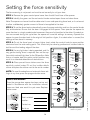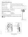
1
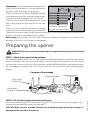
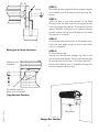
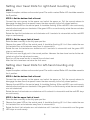
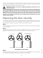
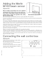
remote control openers
security at your fingertips
prolift 430R
Installation Instructions
EDR4 1171 05/05
opener for roller doors
Toll free helpline
0800 073 0112
Please have your serial
number and model name
available before calling.
www.merlingo.com
1
Important safety instructions for operation
It is vital for the safety of persons to follow all instructions. Save these instructions.
WARNING Do not allow children to play with door controls. Keep remote controls
away from children. The appliance is not intended for use by young children or infirm
persons without supervision.
Merlin strongly recommends the use of optical safety beams on all sites as this
is a non-contact system
Watch the moving door and keep people away until the door is completely
opened or closed.
Use caution when operating the manual release with the door open since it may
fall rapidly due to weak or broken springs or an imbalanced door stand well
clear of the path of the moving door.
Frequently examine the installation, in particular cables, springs and mountings, for signs of wear damage or imbalance. Do not use if repair or adjustment
is needed since a fault in the installation or an incorrectly balanced door may
cause injury.
Your door and opener should be serviced at least annually to ensure safe operation.
Each month check that the drive reverses when the door contacts a 50mm high
object placed on the floor. If check fails contact your Merlin Dealer or Authorised Merlin Installer to adjust the force sensitivity.
Force sensitivity should only be adjusted by a professional installer able to test
force at the leading edge of the door.
This appliance is intended for use in single household domestic dwellings only.
The appliance should not be used in multi-household or high frequency use
dwellings.
Disconnect electric power to the garage door opener before making any repairs
or removing any side covers.
To prevent fire or shock hazard, do not expose the opener to rain or moisture.
There are no user serviceable parts in this appliance. Do not open cabinet as
there is risk of electrical shock.
Important safety instructions for installation
To prevent fire or shock hazard do not expose the opener to rain or moisture.
To avoid electrical shock do not open the cabinet without disconnecting the opener from the mains.
Incorrect installation can lead to severe injury. Follow all installation instructions.
Garage doors are under great spring tension. Do not attempt to adjust spring tension. Do not
loosen any brackets under spring tension. Do not remove springs from the door. Merlin does not
accept responsibility for damage or injury resulting from installing this opener.
2
EDR4 1171 05/05
WARNING It is vital for the safety of persons to follow all instructions. Save these instructions.
To avoid difficulty during installation, do not connect the opener to the mains or run the door
opener until instructed to do so.
Do not use force sensitivity adjustments to compensate for a binding or sticking garage door.
Excessive force may damage the garage door.
Before installing the drive remove all unnecessary ropes or chains and disable any equipment,
such as locks, that is not needed for powered operation.
Before installing the drive check that the door is in good mechanical condition and that it is
correctly balanced. Check that it opens and closes properly.
Install the actuating member for the manual release (red handle on a rope) such that it rests at a
height of less than 1.8m.
Install any fixed control, wired or wireless, within sight of the door but away from moving parts and
at a height of more than 1.5m.
Permanently attach the label warning against entrapment in a prominent place, or near any fixed
control.
Permanently fix the label concerning the manual release adjacent to its actuating member (thread
the cord through the holes in the manual release warning card).
After installation, ensure that the mechanism is properly adjusted and that the drive reverses when
the door contacts a 50mm high object placed on the floor.
The appliance is not intended for use by young children or infirm persons without supervision.
If the supply cord is damaged, it must be replaced by the manufacturer or its service agent or a
similarly qualified person in order to avoid a hazard.
CE compliance after installation (EC countries only)
It is the responsibility of the installer of the opener to ensure that the forces measured at the
leading edge of the door are within the guidelines of BSEN 60335-2-95:2001. This may require
adjustment of the drive and may also require adjustment of the door. Specialised measurement
equipment may be required. Contact Merlin for assistance if necessary. If the measured forces
exceed the guidelines then Merlin M102 non-contact sensors must be fitted.
EDR4 1171 05/05
Site requirements
Electrical Power Supply The opener is for 220-240 Volts AC - 50 Hz. There
must be an earthed power point within 1.6 metres of the mounting position.
Garage Door This opener is designed for a residential roller door, maximum
3m high, 6m wide and 200kg in gross mass. If the garage door is more than 1.9
m high, 2.1 m wide or 70kg in gross mass, it is recommended that safety beams
are fitted or the leading edge force of the garage door tested. Contact your
merlin dealer for further information.
The force required to move the garage door should not exceed 30kg. Check
that it is possible to raise the door by hand through the full height of the opening. The door should operate smoothly, rolling up and down level to the floor
without the door curtain binding, bulging or coning. The door must not jam in
the tracks. If in doubt consult Merlin.
Rolling shutter door
3
Clearances This opener has been designed to fit
MIN
MAX
160
130
most existing roller doors. It can be mounted on
the left or right hand sides of the garage.
MIN
60
There must be at least 160mm between the edge
MIN
70
of the door drum and the inside wall of the garage.
If there is not then the opener will not fit at all.
There must be at least 70mm between the inside
wall of the garage and the free end of the door
shaft.
Installation clearances
There must be at least 60mm between the edge
for right hand mounting
of the door drum and the supporting wall bracket.
There must be a drive spoke inside the drum closer than 130mm from the edge of the door drum.
If there is not then contact Merlin for an adapter.
Door Locks Existing door locks must be removed or disabled. The opener or the door can be
damaged if you try to use it to open a locked door.
Preparing the opener
WARNING Do not connect to the mains power or operate the opener until instructed
to do so.
STEP 1. Check the contents of the package.
Your package should contain: this manual, a warranty sheet, black steel counter-weight bar, remote
control transmitter, cast aluminium drive finger, two drive finger mounting bolts, nuts and spring
washers, two screws with nuts for the weight bar, loosely bolted black plastic stop bracket assembly, red emergency release rope (with manual release warning card) and one assembled door
opener.
Contents of the package
weight bar & Bolts
transmitter, battery
and clip
Drive finger
& Bolts
stop bracket
assembly
STEP 2. Fit the drive finger to the main drive gear.
Ensure the rounded edge of the drive finger flange is in line with the curvature of the gear, that is
rounded corners pointing towards the gear teeth.
CAUTION Bolts must be inserted from the rear of the drive gear into the drive finger, or
damage will be caused to the opener.
4
EDR4 1171 05/05
manual release rope
Outer pair of holes
bolts through from
rear of gear
Inner pair of holes
Drive finger on main drive gear
WARNING Roller doors are under great spring tension. It is important to secure
the door curtain before loosening the brackets holding the door. Merlin does not
accept responsibility for damage or injury resulting from installing this opener. Please read
this manual fully before attempting installation.
Preparing the roller door
WARNING Do not loosen both door support brackets or clamps. Loosening both
door shaft clamps will expose you to the risk of serious personal injury.
STEP 1. Check that there is a power point available and that there is adequate clearance to mount
the opener onto the door in your preferred location. Clearances are listed in the front of this manual.
STEP 2. Roll the door up to the fully open position.
EDR4 1171 05/05
STEP 3. Ensure that the U-bolt on the end of the door opposite the end to which the opener is to
be fitted is tightened securely. This U-bolt holds all the spring
tension on the door once the other
Mark the position of the
U-bolt is released.
shaft on the bracket.
Check this
STEP 4. Before loosening any bolts
U-bolt is
or clamps, mark the position of the
tight
main door-shaft on the wall bracket.
This will allow the door to be re-installed with correct alignment after
Remove
the opener is fitted.
the U-bolt
STEP 5. At the side of the door
that the opener is to be fitted carefully loosen the door shaft U-clamp,
checking that the spring tension inNote: this assumes
R H mounting has
side the roller door drum is not bebeen chosen
ing released.
STEP 6. Remove the U-clamp
from the bracket. Do not allow the
drum to fall by sliding the shaft off
the end of the bracket.
Preparing the roller door
5
Installing the opener
NOTE: If the door is fitted below 2.5m the installer must ensure that all safety guards are
fitted according to this manual.
STEP 1.
You will need assistance for this step. Slide or lift the door shaft clear of the wall bracket and slip
the opener over the shaft. Turn the gear to engage the drive finger onto one of the support spokes
inside the roller drum. Place the door shaft back onto the wall bracket in the position that it was
originally. Refit and tighten the door shaft U-bolt.
It may be necessary to remove the wall bracket. Mark the position before removing the bracket.
5. Swing assembly back
into position on bracket
4. Engage drive
fingers with spoke
3. Slide opener
onto shaft
2. Slide drum
away from bracket
1. Support drum
Installing the Opener
If there is between 60mm and 160mm between the end of
the door shaft and the side wall of the garage:
STEP 2.
When the drive finger is engaged on a spoke, slide the opener along the door shaft until the large
main gear is approximately 15mm clear of the edge of the door curtain. Tighten the two 8mm
clamping bolts facing out of the bracket to secure the opener to the door shaft.
6
EDR4 1171 05/05
It will be difficult to install the opener onto the door shaft. To make it easier, it is possible to split the
drive gear and limit assembly from the motor and controller section. This will result in two smaller
items that must then be re-attached after installing the drive section first.
You will need to remove the limit switch cover, disconnect the limit wiring loom, undo two 8mm bolts
and one 6mm screw. The two sections will now separate quite easily. Note the clutch stator is
connected by a pin at the bottom right hand corner of the drive bracket.
To reconnect take care to engage the clutch stator pin on the lower right hand corner of the drive
bracket. Contact Merlin if you have any doubts about this.
15mm
Tighten
STEP 3.
Re-check all mounting bolts to ensure door, opener
and supporting wall brackets are all securely fastened.
STEP 4.
With the door in the open position fit the Stop
Bracket onto the door shaft at the opposite end
from the garage door opener. This bracket fits hard
against the boss of the door drum spoke and helps
prevent uneven rolling up of the door curtain after
the opener is installed.
STEP 5.
Fit the black steel weight-bar to the bottom centre of the door edge using the 5mm coach bolts
and nuts supplied.
Drive gear to drum clearance
Opposite end
to opener
STEP 6.
Fit the release rope
Tie the red release rope through the hole in the
end of the release handle. Pull the red release rope
to position the clutch lever in the down position.
Ensure the release cord is threaded through the
manual release warning card.
Fit bracket against
boss of drum spokes
EDR4 1171 05/05
Stop Bracket Position
Weight bar
Weight Bar Position
7
Setting the door travel limits
Travel limit
actuator cover
Manual
release
Travel limit
actuator arms
Travel limit
actuator cover
Micro switches
Fine adjusting
screws access
point
Control panel
cover
The procedure for setting the door travel
limits differs depending on which side
of the garage door the opener has been
fitted.
remove
for setup
STEP 1:
To access the limits rotate the limit cover
clockwise to the open position.
Remove the green control panel cover
from the left front face of the opener.
exit delay
Light door
roller: L
tall door
autoclose
open
on
on
R
on
short
long
auto
open
force
STEP 2:
As viewed while looking out of the garage through the doorway, is the opener
on the right-hand or left-hand side?
operate
learn
program
delete
auto
close
force
manual
control
8
EDR4 1171 05/05
close
Setting door travel limits for right-hand mounting only
STEP 1:
Inspect the option switches on the control panel. The switch marked ‘Roller L:R’ should be moved to
the R position.
STEP 2: Set the bottom limit of travel.
Connect the mains power to the opener and switch the power on. Pull the manual release to
disengage the door from the opener. Lower the door manually to the fully closed position.
Observe the red LED on the control panel. It should be flashing. (If the red LED is on continuously,
rotate the front actuator arm clockwise. If the green LED is on continuously, rotate the rear actuator
arm anti-clockwise.)
Rotate the front limit-actuator-arm anti-clockwise until it contacts its microswitch and the red LED
stays on continuously.
STEP 3: Set the upper limit of travel.
Raise the door manually to the fully open position.
Observe the green LED on the control panel. It should be flashing. (If it isn’t then rotate the rear
limit-actuator-arm anti-clockwise away from its microswitch.)
Rotate the rear limit-actuator-arm clockwise until it contacts its microswitch and the green LED
stays on continuously.
The limits are now largely set in the correct position. However the door travel can be further adjusted using the fine adjustment screws.
Each turn of the screw results in around 5mm of door travel.
After the limits have been set close the limit cover.
Setting door travel limits for left-hand mounting only
STEP 1:
Inspect the option switches on the control panel. The switch marked ‘Roller L:R’ should be moved to
the L position.
EDR4 1171 05/05
STEP 2: Set the bottom limit of travel.
Connect the mains power to the opener and switch the power on. Pull the manual release to
disengage the door from the opener. Lower the door manually to the fully closed position.
Observe the red LED on the control panel. It should be flashing. (If the red LED is on continuously,
rotate the front actuator arm clockwise. If the green LED is on continuously, rotate the rear actuator
arm anti-clockwise.)
Rotate the rear limit-actuator-arm clockwise until it contacts its microswitch and the red LED stays
on continuously.
STEP 3: Set the upper limit of travel.
Raise the door manually to the fully open position.
Observe the green LED on the control panel. It should be flashing. (If it isn’t then rotate the rear
limit-actuator-arm anti-clockwise away from its microswitch.)
Rotate the front limit-actuator-arm anti-clockwise until it contacts its microswitch and the green
LED stays on continuously.
9
The limits are now largely set in the correct position. However the door travel can be further adjusted using the fine adjustment screws. Each turn of the screw results in around 5mm of door
travel. After the limits have been set close the limit cover.
WARNING: The door is not safe for unsupervised operation until the force sensitivity has been set.
NOTE Repeated operation of the opener in a short period of time during the setting of force
sensitivity may trigger the thermal cutout of the motor. In this case you will have to wait for
approximately five minutes for the motor to cool sufficiently to continue the installation
process. If the unit has overheated you will hear the relays clicking in response to the
transmitter or pushbutton but the motor will not operate. After cooling down, normal operation is able to resume.
Improving the door security
In most cases the opener acts as a lock on the door. However some doors allow the curtain to slide
up in the tracks even when the drum is held stationary by the opener. In these cases we recommend the addition of bolts or pop-rivets to hold the curtain against the drum:
STEP 1.
Pull the red rope to disengage the clutch. Close the door manually. Push the clutch lever (attached
to the red rope) up.
STEP 2.
Try to manually open the door with the opener engaged. (There will be a clunk as the opener
engages its clutch.) Any excess door curtain may billow out from the top of the drum.
Free curtain
Door closed
Door can be lifted
Add fasteners here
Door secure
Securing door curtain to drum
STEP 3.
To remedy any billowing place gutter-bolts or pop rivets (not supplied) 75mm up from where the
curtain leaves the roll. Secure these through the curtain into the spokes.
10
EDR4 1171 05/05
Billowing
Setting up wireless controls
Wireless controls can operate the opener, or the opener’s courtesy lamp, by sending coded radio
signals. These coded signals use high-security code-hopping.
Wireless controls can be hand-held or fixed to walls, such as a wireless keypad, or a wireless wallswitch.
Up to 20 Merlin wireless controls can be learned by the opener. After this, the 20th wireless control
is over-written in the opener’s memory.
All wireless controls can be deleted from the opener’s memory.
There is a red learn button under the green control panel cover on the front face of the opener. The
small button on a Merlin M-122 wired wall-switch can also be used as the learn button.
If a setting is enabled in the opener, then it is possible to use any existing learned wireless control
as a learn button. (See separate section following.)
To learn a remote button to operate the opener:
Press the learn button for 1-2 seconds, until the courtesy lamp begins to flash slowly.
Press the desired remote button, wait 1 second, press the desired remote button again. The courtesy lamp will stop flashing once learning is complete.
To learn one remote button to operate the opener and another to operate the lamp:
Press the learn button for 1-2 seconds, until the courtesy lamp begins to flash slowly.
Press the desired remote button for control of the opener, wait 1 second, press the desired remote
button for control of the courtesy lamp. The courtesy lamp will stop flashing once learning is complete.
EDR4 1171 05/05
To delete all remote controls from the opener’s memory
Press and hold the learn button for eleven seconds, until the courtesy lamp stops flashing. After six
seconds it will flash fast as a warning. If you release the learn button during this warning period
then the memory will not be wiped.
11
Remote transmitter learning
Remote Transmitter Learning (RTL), when enabled, allows any existing learned wireless control to
be used as a learn button for the learning of additional wireless controls. Note that this feature
trades convenience for security. If it is chosen to disable RTL (the default setting at manufacture is
enabled) then the level of security is increased.
To enable or disable RTL:
Remove the green control panel cover to expose the setup controls. Identify the red learn button
and the black program button.
Hold both of these buttons down for three seconds until the courtesy lamp begins to flash. Release
both buttons.
Six flashes confirms that RTL is now enabled.
Four flashes confirms that RTL is now disabled.
To place the opener in learn mode using RTL:
Select any two or four button Merlin hand held remote control that is already learned in to the
opener. Call this the master remote.
Press the master remote's north and south buttons together for 2-3 seconds.
The courtesy lamp on the opener will begin to repeat a cycle of flashing three times and pausing. If
you have several openers that operate from this master remote, then all these openers will begin to
flash their courtesy lamps.
Press the button on the master remote that would normally operate the desired opener. Now that
opener will go into learn mode, and any other openers that were flashing will return to their normal
standby state.
The courtesy lamp on the opener that is in learn mode will begin to flash slowly. You have 20
seconds to complete the next step. If no signals are received for 20 seconds, the opener will revert
to its normal standby state.
To learn a button to operate the opener:
Press the desired remote button, wait 1 second, press the desired remote button again. The courtesy lamp will stop flashing once learning is complete.
EDR4 1171 05/05
To learn one remote button to operate the opener and another to operate the lamp:
Press the learn button for 1-2 seconds, until the courtesy lamp begins to flash slowly.
Press the desired remote button for control of the opener, wait 1 second, press the desired remote
button for control of the courtesy lamp. The courtesy lamp will stop flashing once learning is complete.
12
Adding the Merlin
M102 beam sensor
(Optional)
NIR Ligh
Merlin strongly recommends the use of optional
t beam
safety beams on all sites as this is a non-contact sysMax 7
metres
tem. If there is any doubt in whether the force at the
leading edge is inside the regulation limit, safety
Non contact beam sensor
beams should be fitted.
Non-contact Near-Infra-Red beam sensors may be required in EC countries.
If sensors are fitted the opener will only close when the sensors are fully functional and where their
beam is unobstructed.
The sensors should be placed either side of the door opening, within 300-mm of the door’s opening, and within 100-mm of the floor. Choose positions that will protect the sensors from accidental
impact or water. If one sensor is marked ‘receiver’ then do not place that sensor where it will be
subjected to bright direct sunlight. The high level of Infra Red light in bright sunlight may temporarily prevent normal operation of the opener.
Switch off the power to the opener. Run the pair of cables from each sensor back to the accessory
terminals on the rear of the opener.
There is no need to connect the cables with any particular polarity.
The door can open regardless of the sensor beam. Only the closing operation is affected by the
state of the beam. If the beam is obstructed, or if the sensors are not functioning, then the door may
still be closed by holding the manual control button down for at least two seconds, and keeping it
held until the door is closed.
Connecting the wall control box
(Optional)
EDR4 1171 05/05
The M-122 wall control box can be wired to
the accessory terminal strip.
This will allow the user to control the opener
and lamp by fixed wiring.
Connect to the accessory terminals marked
'manual control' under the opener, inside the
lamp cover, under a panel.
13
Setting the force sensitivity
The force sensing is not preset and must be set correctly to suit your door.
STEP 1: Remove the green control panel cover from the left front face of the opener.
STEP 2: Identify the green and the red control knobs marked open-force and close-force.
Note: The opener can be set to either determine its own safe operating force level, or it can be set
to allow a deliberately greater amount of force to be applied to the door.
STEP 3: To set the force levels automatically, press the program button and turn the control knobs
fully anticlockwise. Ensure that the door is engaged to the opener. Then operate the opener to
move the door in a single unobstructed movement from one limit position to the other. If no obstruction was sensed during this cycle then the opener will save the settings to memory. Operate the
opener to move the door back to the original limit position. Again, if no obstruction is sensed, the
settings will be stored in memory.
STEP 4: To set the force levels at some higher level, rotate the control knob to some position
clockwise from the auto-setting point. This should only be done by professional installers able to
test force at the leading edge of the door.
STEP 6: Place pre-set force stickers over the force
sensitivity control knobs. Fill out the installer details
sticker and place the sticker next to the serial number.
NOTE: To reset the adaptive and automatic force settings at any time, press the program button once.
exit delay
Light door
roller: L
tall door
autoclose
open
on
on
R
on
short
long
open
Pre-set force
open
force
learn
program
close
force
Date installed:
close
Installer:
on
on
R
on
short
long
auto
Do not remove
or adjust.
For adjustment
contact your
installer.
operate
Note to the installer:
Once the garage door opener has been set up and
tested in accordance with the installation manual,
place one label over each trim pot cover. Replace
button cover
exit delay
Light door
roller: L
tall door
autoclose
operate
delete
learn
delete
program
auto
Pre-set force
Do not remove
or adjust.
For adjustment
contact your
installer.
close
Contact no:
Serial no:
The pre-set force
stickers in place
14
EDR4 1171 05/05
STEP 5: If a very light door is being operated, and if a
very gentle closing force is required, then set the option switch marked ‘Light door’ to the ON position. Note
that on a heavier door this option switch position may
result in unintended detections of obstructions.
Specifications
Replacement light bulb
Mains power required
Suitable for
Curtain edge speed
Maximum rated torque
Maximum door height
Stand-by power consumption
Operating power consumption
Ambient operating temperature
E27 45mm Round, 40W maximum, RC preferred
220V to 240 V, 50 Hz, single phase AC, earthed
domestic roller doors only. Not rated for shutter doors
dependent on drum size - approximately 7-10 seconds per drum
revolution
70Nm
dependent on drum size - approximately 3m (3 drum rotations)
3W maximum
900W maximum
+50C to +400C
Requirements for garage doors
Height:
maximum 3m
Width:
maximum 6m
Gross door mass:
maximum 200kg
If any of these values are exceeded safety beams must be fitted or the leading
edge force of the garage door tested.
The force required to move the garage door should not exceed
30kg.
EDR4 1171 05/05
Rolling shutter door
Overall dimensions
15
Merlin service centres
England
Phone toll free 0800 073 0112
Fax toll free 01709 514 534
Merlin does not accept responsibility for damage or injury resulting from installing this opener. Merlin
reserves the right to change the design and specification without prior notification. Some features or
accessories may not be available in certain markets or areas. Please check with your distributor.
27
16
EDR4 1171 05/05
www.merlingo.com