1
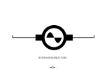
613-10423-00Book Page 1 Monday, March 4, 1996 2:29 PM CentreCOM™ AT-200 Series Single Port Transceiver User Manual PN 613-10423-00 Rev A 951117 613-10423-00Book Page i Monday, March 4, 1996 2:29 PM RADIATED ENERGY U.S. Federal Communications Note: This equipment has been tested and found to comply with the limits for a Class A digital device pursuant to Part 15 of FCC Rules. These limits are designed to provide reasonable protection against harmful interference when the equipment is operated in a commercial environment. This equipment generates, uses, and can radiate radio frequency energy and, if not installed and used in accordance with this instruction manual, may cause harmful interference to radio communications. Operation of this equipment in a residential area is likely to cause harmful interference in which case the user will be required to correct the interference at his own expense. Electrical Safety and Installation Requirements Note: Modifications or changes not expressly approved of by the manufacturer or the FCC, can void your right to operate this equipment. Canadian Department of Communications This digital apparatus does not exceed the Class A limits for radio noise emissions from digital apparatus as set out in the radio interference regulations of the Canadian Department of Communications. Le present appariel numerique n'emet pas de bruits radiolectriques depassant les limites appicables aux appariels numeriques de Classe A. Prescrites dans le reglement sur le brouillage radielectrique edicte par le minestere des Communications Du Canada. This product has been tested and complies with the German Vfg 243/1991 requirements for a Class B device. SAFETY These products have been safety tested by UL to Standard UL 478, CSA to CSA 220 and by TUV to EN60950. The AT-200 series models have been safety tested as “Non-Patient Equipment” by Underwriters Laboratories Inc, to UL544, the Standard for Medical and Dental Equipment. LIGHTNING DANGER DANGER: DO NOT WORK on equipment or CABLES during periods of LIGHTNING ACTIVITY. ! INSTALLATION Operating temperature: This product is designed for a maximum ambient temperature of 50 degrees C. Environmental Air Notice Caution: UL listed for use in other Environmental Air Spaces in Accordance with Article 300-22(C) of the U.S.A National Electrical Code. Note: Product is not Plenum rated All Countries: Install product in accordance with local and National Electrical Codes. STRAHLUNGSENERGIE Bescheinigung des Herstellers/Importeurs Hiermit wird bescheinigt, daß das Single port Transceiver Typenbezeichnung AT-200 in Ubereinstimmung mit den Bestimmungen der BAPT-AmtsblVfg 243/1991 Klasse B funkentstört ist. Der vorschriftsmäßige Betrieb mancher Geräte ( z. B MeBsender) kann allerdings gewissen Einschränkungen unterliegen. Beachten Sie deshalb die Hinweise in der Bedienungsanleitung. Dem Zentralamt fur Zulassungen im Fermeldewesen wurde das Inverkehrbringen dieses Gerätes angezeigt und die Berechtigung zur Überprufung der Serie auf Eienhaltung der Bestimmungen eingeräumt. Von Benutzer zusammengestellte Systeme, die dieses Gerat beihhhalten, müssen den Betimmungen von Vfg 243/1991 Klasse B, entsprechen. SICHERHEIT Die Sicherheitsprüfung dieser Produkte wurde von Underwriters Laboratories Inc. gemäß Norm 478, CSA nach CSA 220 und gemäß TÜV nach EN60950 durchgeführt. i 613-10423-00Book Page ii Monday, March 4, 1996 2:29 PM Die Sicherheitsprüfung erfolgte nur für die Modelle der Serie AT-200 als “nicht für Patienten zugelassene Geräte” durch Underwriters Laboratories Inc. gemäß UL544, der Norm für medizinische und zahntechnische Geräte. GEFAHR DURCH BLITZSCHLAG GEFAHR: Keine Arbeiten am Gerät oder an den Kabeln während eines Gewitters ausführen ! INSTALLATION Betjeningstemperatur: Dieses Produkt wurde für den Betrieb in einer Umgebungstemperatur von nicht mehr als 50° C entworfen. Alle Länder: Installation muß örtlichen und nationalen elektrischen Vorschriften entsprechen. STRÅLINGSENERGI Dette kommercielle produkt opfylder de krav, der i USA stilles til udstyr af Klasse A. Dette produkt opfylder krav, der ifølge German Vfg 243/1991 stilles til udstyr af Klasse B SIKKERHED Disse produkter er blevet sikkerhedstestet af UL til Standard 478, CSA til CSA 220 og af TUV til EN60950. Kun modeller fra serie AT-200 er blevet sikkerhedstestet som “Non-patientapparatur” af Underwriters Laboratories Inc. til UL544, standard for medicinsk og dentalapparatur. FARE UNDER UVEJR FARE: UNDLAD at arbejde på udstyr eller KABLER i perioder med LYNAKTIVITET. ! INSTALLATION Betjeningstemperatur: Dette apparat er konstrueret til en omgivende temperatur på maksimum 50grader C. Alle Lande: Installation af produktet skal ske i overensstemmelse med lokal og national lovgivning for elektriske installationer. STRALINGSENERGIE Dit handelsprodukt werd getest en voldoet aan de Amerikaanse vereisten voor een klasse A toestel. Dit produkt werd getest en voldoet aan de Duitse Vfg 243/1991 vereisten voor een klasse B toestel. VEILIGHEID De veiligheid van deze produkten is door UL getest geworden volgens Norm 478, CSA tot CSA 220 en door TUV volgens EN60950. Alleen de modellen van de AT-200 serie zijn op veiligheid getest geworden als "Niet voor patiënten bestemde uitrusting" door Underwriters Laboratories Inc. volgens UL544, de Norm voor Geneeskundige en Tandheelkundige Uitrusting. GEVAAR VOOR BLIKSEMINSLAG GEVAAR: NIET aan toestellen of KABELS WERKEN bij BLIKSEM. ! ii INSTALLATIE Bedrijfstemperatuur: De omgevingstemperatuur voor dit produkt mag niet meer bedragen dan 50 gradenCelsius. Alle landen: het toestel installeren overeenkomstig de lokale en nationale elektrische voorschriften. 613-10423-00Book Page iii Monday, March 4, 1996 2:29 PM ENERGIE RAYONNEE Ce matériel a été testé et est certifié conforme par la réglementation américaine aux normes définies pour les appareils de classe A. Ce matériel a été testé et est certifié conforme par la réglementation allemande Vfg 243/1991 aux normes définies pour les appareils de classe B. SECURITE La sécurité de ces produits a été testée par UL conformément à la norme du Standard 478, CSA à CSA 220 et par TUV conformément à la norme EN60950. Seuls les modèles de série AT-200 ont été approuvés en tant que “matériel non patient” par Underwriters Laboratories Inc., conformément au standard UL544, la norme des matériels dentaires et médicaux. DANGER DE FOUDRE DANGER: NE PAS MANIER l'équipement ou les CABLES pendant les périodes d'activité orageuse. ! INSTALLATION Temperature De Fonctionnement: Ce produit est capable de tolérer une température ambiante maximum de 50 degrés Celsius Pour tous pays: Installer le produit conformément aux normes électriques nationales et locales. SÄTEILYENERGIA Tämä kaupallinen tuote on testattu ja noudattaa Yhdysvaltojen vaatimuksia luokan A laitteelle. Tämä kaupallinen tuote on testattu ja noudattaa Saksan Vfg 243/1991 -vaatimuksia luokan B laitteelle. TURVALLISUUS UL on turvatestannut nämä tuotteet Standard 478 mukaisesti, CSA standardin CSA 220 mukaisesti ja TUV standardin EN60950 mukaisesti. Underwriters Laboratories, Inc. on turvatarkastanut ainoastaan sarjaan AT-200 kuuluvat laitteet “Ei-potilas laitteina,” standardin UL544 mukaisesti jonka otsikkona on Lääke- ja hammaslääketiedevälineistöstandardi (the Standard for Medical and Dental Equipment). SALAMANISKUVAARA HENGENVAARA: ÄLÄ TYÖSKENTELE laitteiden tai KAAPELEIDEN KANSSA SALAMOINNIN AIKANA. ! ASENNUS KäyttölämpötIla: Tämä tuote on suunniteltu ympäröivän ilman maksimilämpötilalle 50°C. Kaikki maat: Asenna tuote paikallisten ja kansallisten sähköturvallisuusmääräysten mukaisesti. ENERGIA IRRADIATA Questo prodotto commerciale è stato collaudato e risponde ai requisiti U.S.A. per i dispositivi di classe A. Questo prodotto è stato collaudato e risponde ai requisiti della legge tedesca Vfg 243/1991 per i dispositivi di classe B. NORME DI SICUREZZA Questi prodotti sono stati sottoposti a collaudi di sicurezza dai seguenti enti: dalla UL in conformità allo standard 478, dalla CSA in conformità allo standard CSA 220 e dal TÜV in conformità allo standard EN60950. Solo i modelli della serie AT-200 sono stati sottoposti a collaudi di sicurezza in qualità di "strumenti non-paziente" dalla Underwriters Laboratories Inc. in conformità allo standard UL544 per la strumentazione medica e odontoiatrica. iii 613-10423-00Book Page iv Monday, March 4, 1996 2:29 PM PERICOLO DI FULMINI PERICOLO: NON LAVORARE sul dispositivo o sui CAVI durante PRECIPITAZIONI TEMPORALESCHE. ! INSTALLAZIONE Temperatura di funzionamento: Questo prodotto è concepito per una temperatura ambientale massima di 50 gradi centigradi. Tutti i paesi: installare il prodotto in conformità alle vigenti normative elettriche nazionali. UTSTRÅLT ENERGI Dette kommersielle produktet har blitt testet og er i samsvar med amerikanske krav for et AKlasse apparat. Dette produktet har blitt testet og er i samsvar med tyske Vfg 243/1991 krav for et B-Klasse apparat. SIKKERHET Disse produktene er blitt sikkerhetstestet av UL i forhold til Standard 478, CSA i forhold til CSA 220, og av TUV i forhold til EN60950. Bare modellene i AT-200-serien er blitt sikkerhetstestet som “Non-patient equipment” (utstyr som ikke skal brukes på pasienter) av Underwriters Laboratories Inc. i forhold til UL544, standard for medisinsk- og tannlegeutstyr. FARE FOR LYNANTENNELSE FARE: MÅ IKKE BRUKES på utstyr eller ledninger mens LYN-AKTIVITET er i gang. ! INSTALLASJON Driftstemperatur: Dette produktet har blitt fremstilt til bruk med maksimum romtemperatur på eller 50 grader celsius. Alle land: Produktet må installeres i samsvar med de lokale og nasjonale elektriske koder. ENERGIA IRRADIADA Este produto foi testado e atende aos requisitos para dispositivos comerciais de Classe A nos E.U.A. Este produto foi testado e atende aos requisitos Vfg 243/1991 para dispositivos de Classe B na Alemanha. SEGURANÇA Este produtos foram testados pela UL quanto a aspectos de segurança no Padrão 478, CSA a CSA 220 e pela TUV para EN60950 Somente os modelos da série AT-200 foram testados quanto a aspectos de segurança pela Underwriters Laboratories Inc. para UL544, como “equipamentos não destinados a pacientes,” dentro do Padrão para Equipamentos Médico-Dentários. PERIGO DE CHOQUE CAUSADO POR RAIO PERIGO: NÃO TRABALHE no equipamento ou nos CABOS durante períodos suscetíveis de QUEDAS DE RAIO. ! INSTALAÇÃO Temperatura De Funcionamento: Este produto foi projetado para uma temperatura ambiente máxima de 50 graus centígrados. Todos os países: Instale o produto de acordo com as normas federais e locais para instalações elétricas. iv 613-10423-00Book Page v Monday, March 4, 1996 2:29 PM ENERGIA RADIADA Este producto comercial ha sido probado y cumple con las normas requeridas en los EE. UU. para un dispositivo de Clase A. Este producto ha sido probado y cumple con los requisitos Vfg 243/1991 de Alemania para un dispositivo de Clase B. SEGURIDAD La seguridad de estos productos ha sido probada por UL como conforme con la Norma 478, CSA a CSA 220, y por TUV como conforme con EN60950. La seguridad de únicamente los modelos de serie AT-200 como “Equipo que no es para pacientes” ha sido probada por Underwriters Laboratories Inc. como conforme con UL544, la Norma para Equipo Médico y Dental. PELIGRO DE RAYOS PELIGRO: NO REALICE NINGUN TIPO DE TRABAJO O CONEXION en los equipos o en LOS CABLES durante TORMENTAS DE RAYOS. ! INSTALACION Temperatura requerida para la operación: Este producto está diseñado para una temperatura ambiental máxima de 50 grados C. Para todos los países: Monte el producto de acuerdo con los Códigos Eléctricos locales y nacionales. ENERGIUTSTRÅLNING Denna handelsprodukt har testats och befunnits vara i enlighet med U.S.A.s krav för klass A utrustning. Denna produkt har testats och befunnits vara i enlighet med Tysklands Vfg 243/1991 krav för klass B utrustning. SÄKERHET Dessa produkter har säkerhetstestats av UL i enlighet med Standard 478, av CSA i enlighet med CSA 220, och av TUV i enlighet med EN60950. Endast modellerna i serien AT-200 has säkerhetstestats som “Utrustning ej avsedd för patient” av Underwriters Laboratories, Inc., enligt UL544:s standard för utrustning för sjukoch tankvård (the Standard for Medical and Dental Equipment). FARA FÖR BLIXTNEDSLAG FARA: ARBETA EJ på utrustningen eller kablarna vid ÅSKVÄDER. ! INSTALLATION Driftstemperatur: Denna produkt är konstruerad för rumstemperatur ej överstigande 50 grader Celsius. Alla länder: Installera produkten i enlighet med lokala och statliga bestämmelser för elektrisk utrustning. v 613-10423-00Book Page vii Monday, March 4, 1996 2:29 PM Table of Contents Overview ............................................................................................. 1 Installation ......................................................................................... 1 Heartbeat configuration ................................................................ 1 Thick Ethernet installation with coaxial active tap assembly (for model AT-206) ................................................. 2 Data cabling considerations ................................................3 Tapping the cable and assembling the transceiver ..............3 Thick Ethernet installation with coaxial N-series tap (for model AT-208) ................................................................... 5 Data cabling considerations ................................................6 Thin Ethernet installation with BNC tap (for models AT-204 and AT-207) .................................................. 7 Data cabling considerations ................................................8 Attaching AUI drop cables (for all models) ............................... 8 Data cabling considerations ................................................8 Checking Operation ................................................................ 9 List of Figures Figure 1: Location of the Heartbeat Switch ..................................... 2 Figure 2: Assembling the Coaxial Active Tap .................................. 4 Figure 3: 50 Ω Terminator for Thicknet Segment ............................ 5 Figure 4: AT-200 with N-Series Thicknet Backbone Connector (AT-208) .......................................... 6 Figure 5: AT-200 with Thin Coax Backbone Connector (AT-204) ............................................................................... 7 Figure 6: AT-200 with Thin Coax T-Connector (AT-207) ............................................................................... 7 Figure 7: BNC-T with 50 Ω Terminator ............................................ 8 List of Tables Table 1: AT-200 Series Single Port Transceivers ............................ 1 vii 613-10423-00Book Page 1 Monday, March 4, 1996 2:29 PM Overview CentreCOM™ AT-200 Series Single Port Transceivers are highly reliable compact Media Access Units (MAUs) for users of Ethernet Local Area Networks (LANs). They provide the electronic and physical interface between the IEEE 802.3 coaxial cable and a Data Terminal Equipment (DTE) station. The AT-200 transceiver is available in a variety of configurations, all of which meet the transceiver compliance requirements of IEEE 802.3 and are compatible with Ethernet Version 1.0 and 2.0. The use of industry-standard connectors ensures plug compatibility with all existing cable connectors used in Attachment Unit Interface (AUI), thicknet (10BASE5) or thinnet (10BASE2) installations. Table 1 shows the AT-200 series transceiver models available. Table 1: AT-200 Series Single Port Transceivers Model Cable Connector AT-204 10BASE2 Bayonet Nut Couple (BNC) AT-205 N/A No Backbone Connector AT-206 10BASE5 Coaxial Active (Stinger) Type Tap AT-207 10BASE2 BNC-T AT-208 10BASE5 Coaxial N-Series Installation Installation of an AT-200 series transceiver involves checking heartbeat configuration, installing the tap body (if it is shipped separated or has been removed) and connecting the cables properly. The AT-204, AT-207 and AT-208 are shipped with the coaxial tap body installed. With the AT-206, you install the coaxial active tap body when you tap the 10BASE5 cable. The AT-205 comes with no tap body. Heartbeat configuration Note All transceivers are shipped with the Heartbeat switch in the “0” (disabled) position. With few exceptions, the Signal Quality Error (SQE)/Heartbeat (i.e., Collision Presence Test) should be disabled; i.e., the Heartbeat switch should be left in the “0” (disabled) position. Check the device’s documentation to determine whether to enable SQE/Heartbeat. In most cases, when the AUI port is connected to a repeater or another node, the switch must be set to “0” to eliminate the possibility of excessive collisions. The switch should be set to “1” (enabled) with some older Data Communication Equipment (DCE) repeaters and Network Interface Controller (NIC) cards that take advantage of the heartbeat signal. 1 613-10423-00Book Page 2 Monday, March 4, 1996 2:29 PM When necessary, you can enable the SQE test using the Heartbeat switch located on the Printed Circuit Board (PCB) inside the transceiver body. This must be done without the tap body installed in the transceiver. Checking and setting the SQE/Heartbeat switch 1. If the tap body is not installed in the transceiver (for models AT-205 and AT-206), skip to step 3. 2. To remove the tap body from the transceiver, remove the two panhead screws and slide the tap body out. 3. Locate the PCB inside the tap body opening. See Figure 1. With the transceiver facing you, the SQE/Heartbeat switch is on the right side of the circuit board. Set the switch to the desired setting (“1” = SQE enabled; “0” = SQE disabled). 4. Install the tap body. Tap body opening Transceiver body Panhead screw (2) Figure 1: Location of the Heartbeat Switch Thick Ethernet installation with coaxial active tap assembly (for model AT-206) Before installing the AT-206 Single Port Transceiver, check to see that the transceiver package contents are complete. If any of the following items are missing or damaged, contact your sales representative. ❑ ❑ ❑ ❑ 2 AT-200 Series Single Port Transceiver AT-06 tap kit Clamp/pressure-block assembly Tap body Braid terminators (2) Probe assembly Protective dust cover Button head socket screw Manual Warranty card 613-10423-00Book Page 3 Monday, March 4, 1996 2:29 PM AT-200 Single Port Transceiver Data cabling considerations. When configuring 10BASE5 coax segments, IEEE 802.3 specifications provide the following rules to follow: ❑ ❑ ❑ ❑ ❑ ❑ MAU attachments limited to 100 per segment MAU attachments spaced at multiples of 2.5 meters (8.2 ft.) measured accurately from the cable end (50 Ω terminator included) Segment length cannot exceed 500 meters (1,640 ft.) Worst case “end-to-end” propagation delay for the segment is 2165 ns Propagation delay of 10BASE5 Ethernet coax is calculated at 4.33 ns/ meter Both ends of the segment must be terminated with a 50 Ω termination with a power rating of 0.5 watts or greater Earth grounding of the segment shield must take place at only one point on the cable Tapping the cable and assembling the transceiver. In addition to the tap kit supplied with the AT-206, you also need the following tools supplied as accessory AT-1220-K: ❑ ❑ Hex wrench Combination hex nut driver and coring drill The clamp assembly has a frame that slides onto the tap body, a pressure block that holds the cable in place and a button head socket screw. The tap body features a cable channel that retains the cable and an internal guide slot to accept the transceiver’s PCB. The braid terminators are designed to pierce the cable jacket and provide a secure ground. The probe assembly features a spring-loaded contact (stinger) and threads into the tap body, ensuring permanent contact with the center conductor. To install the tap body, cable and clamp assembly 1. Before attaching the tap to the transceiver, make sure the transceiver’s SQE/Heartbeat switch is in the correct position. Refer to the “Heartbeat configuration” on page 1. 2. Insert the two braid terminators into the tap body. Refer to the exploded view of the tap in Figure 2. 3. Determine a tapping location on the cable. These may be found on the cable at 2.5 meter (8.2 ft.) intervals (usually denoted by black marks). 3 613-10423-00Book Page 4 Monday, March 4, 1996 2:29 PM 4. Place the cable in the cable channel of the tap body. Socket screw Clamp assembly Pressure block Cable Braid terminator (2) Tap body Probe assembly Figure 2: Assembling the Coaxial Active Tap 5. Slide the clamp assembly onto the tap body until it stops. 6. Using the hex wrench, thread the button socket screw into the clamp frame until the pressure block bottoms on the clamp track and holds the cable securely. Caution Use only the coring drill supplied separately in the coaxial active connector installation tool kit, model AT-1220-K, to drill the thick Ethernet cable. ! 7. Insert the combination nut driver/coring drill through the hole in the tap body. Drill through the cable to the center conductor. The coring drill end has a stop to prevent overdrilling. 8. Inspect the hole to be sure no particles remain. Caution ! 9. Hand-tighten only. Do NOT over-tighten or damage could result. Using the nut driver end of the tool assembly, thread the probe assembly into the tap body until the probe assembly is firmly seated. 10. If installed, remove the two long panhead screws from the transceiver body. 4 613-10423-00Book Page 5 Monday, March 4, 1996 2:29 PM AT-200 Single Port Transceiver 11. To install the transceiver, align the opening on the transceiver body so that the diagnostic LEDs are facing you. (The transceiver is reversible front to back.) Gently guide the tap body into the transceiver opening so that the probe post and the two braid terminator posts are aligned with the three gold-colored circuit board contacts. Then slide the tap assembly fully into the slot. 12. Secure the tap body to transceiver with the two panhead screws. Note Replacement probe assembly and braid terminators are available as tool kit AT-060-K. 13. Be sure the cable is terminated at both ends. Figure 3 shows a terminator installed at one end of a thicknet segment. Cable Thicknet terminator Figure 3: 50 Ω Terminator for Thicknet Segment Thick Ethernet installation with coaxial N-series tap (for model AT-208) Before installing the AT-208 Single Port Transceiver, check to see that the transceiver package contents are complete. If any of the following items are missing or damaged, contact your sales representative. ❑ ❑ ❑ AT-200 Series Single Port Transceiver with AT-08 tap Manual Warranty card No assembly of the transceiver is required. It comes with the tap body factory installed. See Figure 4. 5 613-10423-00Book Page 6 Monday, March 4, 1996 2:29 PM The SQE/Heartbeat is factory set to the “0” (disabled) position. Unless your application calls for the heartbeat signal to be enabled, leave this switch in the “0” position. (See “Heartbeat configuration” on page 1.) Figure 4: AT-200 with N-Series Thicknet Backbone Connector (AT-208) Data cabling considerations. When configuring 10BASE5 coax segments, IEEE 802.3 specifications provide the following rules to follow: ❑ ❑ ❑ ❑ ❑ ❑ MAU attachments limited to 100 per segment MAU attachments spaced at multiples of 2.5 meters (8.2 ft.) measured accurately from the cable end (50 Ω terminator included) Segment length cannot exceed 500 meters (1,640 ft.) Worst case “end-to-end” propagation delay for the segment is 2165 ns Propagation delay of 10BASE5 Ethernet coax is calculated at 4.33 ns/ meter Both ends of the segment must be terminated with a 50 Ω termination with a power rating of 0.5 watts or greater Earth grounding of the segment shield must take place at only one point on the cable Attach the N-series tap to cable 1. Note 2. 6 Attach 10BASE5 coaxial cable, using male N-series connectors, to either end of the transceiver’s N-series connector. There is no internal termination on the AT-200 series transceiver. Be sure both sides of the N-series connector on the tap body are connected to a cable. Be sure the cable is terminated at both ends. Figure 3 on page 5 shows a terminator installed at one end of a thicknet segment. 613-10423-00Book Page 7 Monday, March 4, 1996 2:29 PM AT-200 Single Port Transceiver Thin Ethernet installation with BNC tap (for models AT-204 and AT-207) Before installing the AT-204 or AT-207 Single Port Transceiver, check to see that the transceiver package contents are complete. If any of the following items are missing or damaged, contact your sales representative. ❑ ❑ ❑ AT-200 Series Single Port Transceiver with AT-04 or AT-07 tap Manual Warranty card No assembly of the transceiver is required. It comes with the tap body factory installed. Figure 5 shows an AT-204 transceiver, which is used with a separate T-connector, and Figure 6 shows an AT-207, which is ready to attach to the thinnet backbone. The AT-204 enables you to take the transceiver off the network without interrupting traffic on the segment. Figure 5: AT-200 with Thin Coax Backbone Connector (AT-204) Figure 6: AT-200 with Thin Coax T-Connector (AT-207) 7 613-10423-00Book Page 8 Monday, March 4, 1996 2:29 PM The SQE/Heartbeat is factory set to the “0” (disabled) position. Unless your application calls for the heartbeat signal to be enabled, leave this switch in the “0” position. (See “Heartbeat configuration” on page 1.) Data cabling considerations. When configuring 10BASE2 coax segments, IEEE 802.3 specifications provide the following rules to follow: ❑ ❑ ❑ ❑ ❑ ❑ MAU attachments limited to 29 per cable segment MAU attachments spaced at no less than 0.5 meter (1.64 ft.) Segment length cannot exceed 185 meters (607 ft.) Worst case propagation “end-to-end” propagation delay for the segment is 950.9 ns Propagation delay of 10BASE2 Ethernet cable is 5.14 ns/meter Both ends of the segment must be terminated with a 50 Ω termination with a power rating of 0.5 watts or greater Earth grounding of the segment shield must take place at only one point on the cable Attach the BNC connector to cable 1. Plug a BNC-T connector into the BNC receptacle. 2. Plug in the 10BASE2 coaxial cable. If the AT-200 series transceiver is between nodes on the cable, attach a thin coax segment to each side of the T-connector. If the transceiver is at the end of the segment, attach a thin coax segment to one side of the T and a 50 Ω terminator to the other side as shown in Figure 7. Cable Thinnet terminator Figure 7: BNC-T with 50 Ω Terminator Note There is no internal termination on the AT-200 series transceiver. Do not plug a thinnet coaxial cable directly into the BNC connector on the tap body without a T-connector. Attaching AUI drop cables (for all models) Data cabling considerations. AUI or Drop cables are governed by the following IEEE 802.3 specification rules: ❑ ❑ 8 Length cannot exceed 50 meters (164 ft.) Attachments may be made only to the cable ends at the 15-pin D-subminiature connector 613-10423-00Book Page 9 Monday, March 4, 1996 2:29 PM AT-200 Single Port Transceiver ❑ ❑ ❑ ❑ AUI cables may have a maximum 257 ns propagation delay, as used for computing the worst case propagation delay of a cable system AUI cable propagation delay is approximately 5.13 ns/meter AUI cable internally consists of four shielded twisted pair wires with an overall shield and drain wire; a 15-pin D-subminiature male connector at one end and a 15-pin D-subminiature female connector at the other end Cable impedance is nominally 78 Ω AUI cable typically connects a transceiver attached to a coaxial segment to a DTE (workstation). Attach the AUI port to cable Caution If power appears at any pin other than 6 (power return) and 13 (power), connecting the cable to the transceiver might result in severe damage to the transceiver and void your warranty. 1. Connect the cable at the station DTE end and test the pins at the transceiver end to make sure that power does not appear at any pins other than 6 and 13. 2. Carefully insert the 15-pin D-subminiature connector into the connector on the transceiver. 3. Move the slide lock to the locked position; this engages the lock posts on the transceiver. 4. Check the Power indicator on the side of the transceiver to make sure it is enabled. Checking Operation Once installation is complete, make sure that the Power indicator is illuminated. 1. The Power indicator changes color depending upon which position the heartbeat switch is set. 2. An amber color indicates that heartbeat is enabled (“1” position). A green color indicates that heartbeat is disabled (“0” position). 9 613-10423-00Book Page 10 Monday, March 4, 1996 2:29 PM Technical Support Fax Order Form Name ___________________________________________________________ Company ________________________________________________________ Address _________________________________________________________ City ____________________ State/Province ____________________________ Zip/Postal Code _______________ Country ____________________________ Phone ___________________________ Fax ____________________________ Incident Summary Model number of Allied Telesyn product I am using _______________________ Network software products I am using (e.g., network managers)______________ _______________________________________________________________ Brief summary of problem___________________________________________ _______________________________________________________________ _______________________________________________________________ Conditions (List the steps that led up to the problem.)______________________ _______________________________________________________________ _______________________________________________________________ _______________________________________________________________ Detailed description (Please use separate sheet) Technical Support Fax Numbers: Asia Singapore, Taiwan, Thailand, Malaysia, Indonesia, Korea, Hong Kong, Philippines, China, India (+65) 383-2079 France France, Belgium, Luxembourg, Holland, Italy, Spain, Australia, New Zealand, Greece, Middle East, Africa, South America (+33) 1-6928-3749 Germany Germany, Switzerland, Austria, Eastern Europe (+49) 30-435-70-650 North America United States, Canada, Mexico (206)-481-3790 United Kingdom United Kingdom, Denmark, Norway, Sweden, Finland, Iceland (+44) 1-865-390-002 10 613-10423-00Book Page 11 Monday, March 4, 1996 2:29 PM AT-200 Single Port Transceiver CentreCOM AT-200 Manual Feedback Form Please tell us what additional information you would like to see discussed in the manual. If there are topics you would like information on that were not covered in the manual, please photocopy this page, answer the questions and fax or mail this form back to Allied Telesyn. The mailing address and fax number are at the bottom of the page. Your comments are valuable when we plan future revisions of the manual. I found the following the most valuable ________________________________ _______________________________________________________________ _______________________________________________________________ _______________________________________________________________ _______________________________________________________________ _______________________________________________________________ I would like more information on the following ___________________________ _______________________________________________________________ _______________________________________________________________ _______________________________________________________________ _______________________________________________________________ _______________________________________________________________ I would find the manual more useful if _________________________________ _______________________________________________________________ _______________________________________________________________ _______________________________________________________________ _______________________________________________________________ _______________________________________________________________ Please fax or mail your feedback. Fax to 1-206-481-3790. Or mail to: Allied Telesyn Technical Publications Department 19015 North Creek Parkway, Suite 200 Bothell, WA 98011 USA 11 613-10423-00Book Page 12 Monday, March 4, 1996 2:29 PM CentreCOM is a trademark of Allied Telesyn International Corp. Copyright 1994 Allied Telesyn International Corp. All rights reserved. No part of this publication may be reproduced without prior written permission from Allied Telesyn International Corp. Allied Telesyn International Corp. reserves the right to make changes in specifications and other information contained in this document without prior written notice. The information provided herein is subject to change without notice. In no event shall Allied Telesyn International Corp. be liable for any incidental, special, indirect, or consequential damages whatsoever, including but not limited to lost profits, arising out of or related to this manual or the information contained herein, even if Allied Telesyn International Corp. has been advised of, known, or should have known, the possibility of such damages. Allied Telesyn 950 Kifer Road Sunnyvale, CA 94086 USA Tel (800) 424-4284 • Fax (408) 736-0100 Technical Support Tel (800) 428-4835 • Fax (206) 481-3790