1
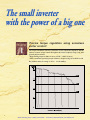
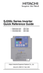
Artisan Technology Group is your source for quality
new and certified-used/pre-owned equipment
• FAST SHIPPING AND
DELIVERY
• TENS OF THOUSANDS OF
IN-STOCK ITEMS
• EQUIPMENT DEMOS
• HUNDREDS OF
MANUFACTURERS
SUPPORTED
• LEASING/MONTHLY
RENTALS
• ITAR CERTIFIED
SECURE ASSET SOLUTIONS
SERVICE CENTER REPAIRS
Experienced engineers and technicians on staff
at our full-service, in-house repair center
WE BUY USED EQUIPMENT
Sell your excess, underutilized, and idle used equipment
We also offer credit for buy-backs and trade-ins
www.artisantg.com/WeBuyEquipment
InstraView REMOTE INSPECTION
LOOKING FOR MORE INFORMATION?
Visit us on the web at www.artisantg.com for more
information on price quotations, drivers, technical
specifications, manuals, and documentation
SM
Remotely inspect equipment before purchasing with
our interactive website at www.instraview.com
Contact us: (888) 88-SOURCE | [email protected] | www.artisantg.com
Sensorless Vector Control
Actual Size (SJ100-004NFE, 004NFU)
All Rights Reserved,Copyright ©2002,Hitachi,Ltd.
Artisan Technology Group - Quality Instrumentation ... Guaranteed | (888) 88-SOURCE | www.artisantg.com
The small inverter
with the power of a big one
Precise torque regulation using senseless
vector control!
The torque calculation software (sensorless vector control) developed by Hitachi
ensures accurate torque control throughout the entire frequency range, even with
general purpose motors.
• High starting torque of 200%or more (3.7kW~ : 180% or more)
• 100% continuous operating torque within a 1:10 speed range (6 to 60 Hz/5 to 50
Hz) without motor de-rating. (3.7kW~: 1:3 (20~60Hz))
Example of SJ100-015NFE with Hitachi 1.5kW 4 pole totally enclosed type motor
1
Artisan Technology Group - Quality Instrumentation ... Guaranteed | (888) 88-SOURCE | www.artisantg.com
CONTENTS
W
Features
P1~4
W
Standard Specifications
P5
W
Dimensional Drawings
P6~7
W
Operation
W
Function List
W
Terminal Functions
P13
W
Protective Functions
P14
W
Connection Diagram
P15
W
Applicable Wiring Apparatus and Options
P16
W
For Correct Operation
P8
P9~12
P17~18
Advanced Functions Condensed in One Unit
X Auto tuning to set motor constants
X Second motor setting (Provision to set second motor constants)
X PID control provided as standard
X 16 –stage multispeed operation
X Instantaneous power failure retry
(frequency stabilization)
X Intelligent terminal system
allows you to select only the
necessary functions
from a full lineup of
enhanced functions.
X FAN ON/OFF selection
to provide longer cooling
fan life
X Incorporated rush current
prevention circuit
2
Artisan Technology Group - Quality Instrumentation ... Guaranteed | (888) 88-SOURCE | www.artisantg.com
Compact, Powerful, Intelligent
and Easy to Use
Perfect matching to Constant torque load
The powerful and intelligent SJ100 inverter series solves your
applications requirements for high torque at low speeds.
[Dynamic braking circuit incorporated as standard]
X CONVEYOR X TRUCK
X EXTRUDER X MIXER
X LIFT etc.
Simple Operation By keypad or external
input signals
The SJ100 can be started by pressing
the RUN button or receiving an
external signal through the terminal.
Speed can be changed by standard
potentiometer, keypad or external
signals. Functions are grouped for
quick, easy setting.
Compact Size Saves Space
Installation space is reduced by
56% from the J100 Series and
11% from the compact L50 Series.
This allows downsizing of your
system installation.
3
Artisan Technology Group - Quality Instrumentation ... Guaranteed | (888) 88-SOURCE | www.artisantg.com
Network-Compatible World Standard Machine
Expands Global Business
The SJ100 Series of world standard machines provide global performance.
X European low–voltage directive compliant, EMC directive compliant
(with dedicated noise filter)
X UL, c–UL standards
X C–Tick (Australian EMC requirment, with dedicated noise filter)
The line -up includes models
compatible with DeviceNet.
<CE >
<UL>
<C–UL>
<C–Tick>
Model Type List
SJ100 - 004 N F E
Series name
Applicable motor rating
002 0.2kW
075 7.5kW
E:European version for Europe, Australia, Singapore,etc.
U:UL version for North America
F:Operator panel equipped
Input power specification
L:Three-phase 200V class
N:Single-/three-phase 200V class
H:Three-phase 400V class
Applicable motor rating ( kW)
Single-/Threephase 200V
0.2
0.4
0.55
0.75
1.1
1.5
2.2
3.0
3.7
4.0
5.5
7.5
NFE type
Eurpean
NFU type
Version
(xxE type) Three-phase
LFU type
200V
UL
Version
(xxUtype) Three-phase HFE type
400V
HFU type
NFE type
Single-/ThreeDevice Net phase 200V
NFU type
Compatible
[SJ100DN] Three-phase
LFU type
(xxE type) 200V
(xxUtype)
Three-phase
400V
HFE type
HFU type
4
Artisan Technology Group - Quality Instrumentation ... Guaranteed | (888) 88-SOURCE | www.artisantg.com
Standard Specifications
Item
200 V Class
Model (S J100-)
Protective structure:
Applicable motor(kW)
0.2
Rated capacity(kVA)(240V/460V) 0.6
0.55 0.75 1.1 1.5 2.2 3.7 5.5 7.5
1.2 1.6 2.0 3.3 4.5 7.2 9.9 13.3
1-phase : 200~240V+5%/-10%, 50/60Hz +/-5%
3-phase : 200~230V+10%/-10%,50/60Hz+/-5% (037~075LFU :3-phase only)
3-phase 200~240V (corresponding to input voltage)
Rated input voltage
Rated output voltage
Rated output current (A)
Control method
1.6
0.4
1.0
2.6
3.0
4.0
5.0
0.75
1.9
1.5
3.0
2.2
4.3
3.0
6.2
4.0
6.8
5.5 7.5
10.3 12.7
3-phase380~460+/-10%,50/60Hz+/-5%
3-phase 380~460V (corresponding to input voltage)
7.8
8.6
13
16
0.5 ~ 360 Hz
Digital command: w 0.01% of the Max. frequency
Analog command: w 0.1% (25!Cw10!C) of the Max. frequency
Frequency accuracy
Digital: 0.1 Hz, Analog: Max. frequency/1000
V/F optionally variable, V/F control (constant torque, reduced torque), sensorless vector control
Frequency setting resolution
Volt./Freq. characteristic *5
150%, 60 seconds
Overload current rating
Acceleration/deceleration time
0.1~3000 sec. (linear or S-curve acceleration/deceleration), second acceleration/deceleration setting available
200%or more
Starting torque*6
Dynamic braking *7
Approx. 100%
(without external resistor)
Dynamic braking *7
(with external resistor)
DC braking
Approx.70%
Approx. 150%
180%or more
Approx.20%
200%or more
Approx. 100% Approx. 70%
Approx.100% Approx.80%
Approx.150%
180%or more
Approx.20%
Approx.100%
Approx.80%
Operating frequency, time, and braking force variable
Up ( 1 ) and down ( 2 ) keys/Value setting keys
Digital operator panel
Frequency Potentiometer
setting
External signal *8
Analog setting
0~10 VDC (input impedance 10kΩ)
4~20mA (input impedance 250Ω), Potentiometer: 1kΩ to 2kΩ (2W) Variable resister
Input Forward Digital operator panel
signal /Reverse
External signal
run
Output
signal
0.4
1.1
8.0 11.0 17.5 24
32 1.5 2.5 3.8 5.5
Sine-wave pulse width modulation (PWM) control
Output frequency range *4
Braking
400 V Class
002NFE 004NFE 005NFE 007NFE 011NFE 015NFE 022NFE - 004HFE 007HFE 015HFE 022HFE 030HFE 040HFE 055HFE 075HFE
002NFU 004NFU - 007NFU - 015NFU 022NFU 037LFU 055LFU 075LFU 004HFU 007HFU 015HFU 022HFU - 040HFU 055HFU 075HFU
IP20
Run/Stop (Forward/Reverse run change by command)
Forward run/stop, Reverse run/stop
Operation command available at terminal assignment (1a/1b selectable)
Intelligent input terminal
FW (Forward run comand), RV (reverse run command), CF1~CF4 (multi-stage speed setting), JG (jogging command),
2CH (2-stage acceleration/deceleration command), FRS (free run stop command), EXT (external trip), USP (USP function), SFT (software lock),
AT (analog current input select signal), RS (Reset), PTC (Thermal protection), DB(external DC braking command), SET(2nd setting selection),
UP (remote control, acceleration), DWN (remote control, deceleration)
Intelligent output terminal
RUN (running signal), FA1,2 (frequency arrival signal), OL (overload advance notice signal), OD
(deviation signal at PID control), AL (alarm signal)
Frequency monitor
PWM output; Select analog output frequency monitor, analog output current monitor or digital
output frequency monitor
Alarm output contact
OFF for the inverter alarm (1C contact output) (possible to change to ON for the alarm)
Other functions
AVR function, curved acceleration/deceleration, upper and lower limiters, 16-stage speed, fine adjustment of start
frequency, carrier frequency change (0.5to16Kz ) frequency jump, gain and bias settung, process jogging, electronic
thermal level adjustment, retry function, trip history monitor, 2nd setting selection, auto tuning, fan on/off selection
Protective function
Overcurrent, overvoltage, undervoltage, overload, extreme high temperature, CPU error, memory
error, ground fault detection at startup, internal communication error,electronic thermal, CT error
Operating
environment
Ambient/storage
temperature/humidity
Vibration *11
Location
-10~50!C (*9)/-25~70!C (*10)/20~90% (no condensation)
5.9 m/s2 (0.6G), 10~55 Hz
Altitude 1,000 m or less, indoors (no corrosive gases or dust)
Munsell 8.5YR6.2/0.2,cooling fins in base color of aluminum
Coating color
Option
Weight(kg)
0.7
Remote operator unit, copy unit, cables for the units, braking unit, braking resistor, AC reactor,
DC reactor, noise filter
0.85 0.85 1.3 1.3 2.2 2.8 2.8 5.5 5.7 1.3 1.7 1.7 1.8 2.8 2.8 5.5 5.7
*1: The protection method conforms to JEM1030.
*2: The applicable motor refers to Hitachi standard 3-phase motor (4-pole). To use
other motors, care must be taken to prevent the rated motor current from exceeding
the rated output current of the inverter.
*3: The output voltage decreases as the main power supply voltage decreases. (Except
for use of the AVR function)
*4: To operate the motor beyond 50/60 Hz, consult the motor manufacturer about the
maximum allowable rotation speed.
*5: SLV selected, set carrier frequency more than 2.1kHz.
*6: At the rated voltage when using a Hitachi standard 3-phase, 4-pole moter.(When
selecting high starting torque flux vector contlrol)
*7: The braking torque at capacitive feedback is the average deceleration torque at the
shortest deceleration (stoppage from 50 Hz) of the motor itself. It is not the
continuous regenerative braking torque. And the average deceleration torque
varies with motor loss. This value decreases when operating beyond 50/60 Hz. If a
large regeneration torque is required, the optional braking resistor should be used.
*8: The frequency command is the maximum frequency at 9.8 V for input voltage 0 ~ 10
VDC, or at 19.6 mA for input current 4 ~ 20 mA. If this characteristic is not
convenient, contact your Hitachi sales representative.
*9: To use the inverter at 40!C or higher, reduce carrier frequency 2.1 kHz and derate
output current 80%, and remove the top cover.
*10: The storage temperature refers to the short-term temperature during transport.
*11: Conforms to the test method specified in JIS C0040 (1999). For the model types
excluded in the standard specifications, contact your Hitachi sales representative.
5
Artisan Technology Group - Quality Instrumentation ... Guaranteed | (888) 88-SOURCE | www.artisantg.com
Dimensional Drawings
V SJ100-002NFE, 004NFE, 005NFE
V SJ100-007NFE, 011NFE, 004HFE
002NFU, 004NFU
007NFU, 004HFU
model
002NFE
002NFU
004NFE
005NFE
004NFU
V SJ100- 015NFE, 015NFU
D
93
107
V SJ100-007HFE, 015HFE, 022HFE
007HFU, 015HFU, 022HFU
V SJ100-022NFE, 030HFE, 040HFE
022NFU, 037LFU, 040HFU
✽ 007HFE , 007HFU
with out FAN
VSJ100-055LFU,055HFE,055HFU,
075HFE,075HFU
V SJ100- 075LFU
6
Artisan Technology Group - Quality Instrumentation ... Guaranteed | (888) 88-SOURCE | www.artisantg.com
Dimensional Drawings
V FFL100-SB3, LB3
V FFL100-HB32
V FFL100-SB5, HB6
V FFL100-SB11, HB11, HB17
Noise filter
Inverter model
Input Power Source
Inverter model
SJ100-002NF
004NF
*
*
SJ100-005NFE
007NF
*
SJ100-011NFE
015NF
022NF*
*
1-phase 200V class
3-phase 200V class
1-phase 200V class
3-phase 200V class
FFL100-SB3
FFL100-LB3
FFL100-SB5
FFL100-HB6
1-phase 200V class
FFL100-SB11
3-phase 200V class
FFL100-HB11
SJ100-037LFU
3-phase 200V class
FFL100-HB17
SJ100-055LFU
075LFU
3-phase 200V class
FFL100-HB32
SJ100-004HF
007HF
015HF
3-phase 400V class
FFL100-HB6
3-phase 400V class
FFL100-HB11
3-phase 400V class
FFL100-HB32
***
SJ100-022HF
*
030HFE
040HF
*
SJ100-055HF
075HF*
*
7
Artisan Technology Group - Quality Instrumentation ... Guaranteed | (888) 88-SOURCE | www.artisantg.com
Operation
The SJ100 Series can be easily operated with the digital operator panel equipped as standard in the main unit.
For remote operation, the remote operator unit is available as an option.
Power lamp
Monitor section (LED)
Displays the monitored frequency,
motor current, motor rpm, or alarm
condition.
Indicates ON/OFF of the control
circuit power supply.
Monitor lamp
Monitor lamp
Indicates the monitor item.
Indicates the monitor item.
Run key
Frequency setting Potentiometer
Press to start the motor.
Stop/Reset key
Store key
Press to stop the motor or to cancel
the alarm.
Use to store the set data.
Function key
Up/down keys
Scroll the function code No. or
change the setting.
(1) Setting the maximum frequency
Function code appears.
or the previously
monitored value is displayed.
POWER
RUN
PRG
Turn on the
power.
RUN
A
PRG
STOP
RESET
RUN
1
Press the
FUNC key.
MAX
2
STR
A
PRG
2
MAX
STR
Display
using the up 1
and down 2 keys.
The previous set value
is displayed.
appears.
POWER
Press the
up key 1
three times.
RUN
MIN
1
FUNC
POWER
Hz
STOP
RESET
RUN
MIN
FUNC
POWER
Hz
appears.
appears.
RUN
A
PRG
STOP
RESET
RUN
1
Hz
A
STOP
RESET
RUN
MIN
FUNC
POWER
Hz
2
Press the
FUNC key.
MAX
STR
1
2
MAX
STR
The setting is complete
(
appears).
The set value is updated.
POWER
MIN
FUNC
POWER
POWER
RUN
Hz
RUN
Hz
RUN
Hz
RUN
Hz
PRG
A
PRG
A
PRG
A
PRG
A
STOP
RESET
RUN
FUNC
1
STOP
RESET
RUN
MIN
2
Press the
FUNC key.
MAX
STR
MIN
1
FUNC
2
MAX
STR
Change the set value
using the up 1 and
down 2 keys.
STOP
RESET
RUN
MIN
FUNC
1
2
MAX
STR
Press the
STR key to
enter the value.
STOP
RESET
RUN
MIN
FUNC
1
1
2
MAX
STR
(2) Running the motor (using the Potentiometer)
The motor rotates at the frequency
set by the potentiometer.
or the previously
monitored value is displayed.
POWER
RUN
Hz
PRG
Turn on the
power.
A
STOP
RESET
RUN
MIN
1
FUNC
2
MAX
STR
The motor stops.
POWER
Press the RUN key
and rotate the
Potentiometer.
RUN
Hz
PRG
A
MIN
FUNC
1
2
Hz
PRG
STOP
STOP
RESET
RUN
POWER
RUN
MAX
STR
Press the RESET key
to stop the motor.
A
STOP
RESET
RUN
MIN
FUNC
1
2
MAX
STR
(Operating frequency monitor)
(3) Monitoring the output current value
or the previously
monitored value is displayed.
Function code appears.
POWER
RUN
PRG
Turn on the
power.
RUN
A
PRG
MIN
FUNC
1
2
POWER
Hz
STOP
RESET
RUN
MAX
STR
appears.
Press the
FUNC key.
RUN
A
PRG
MIN
FUNC
1
2
MAX
STR
POWER
POWER
Hz
STOP
RESET
RUN
Output current value is
displayed.
Display
using the up 1
and down 2 keys.
Hz
RUN
A
PRG
STOP
RESET
RUN
MIN
FUNC
1
2
MAX
STR
Press the
FUNC key.
Hz
A
STOP
RESET
RUN
MIN
FUNC
1
2
MAX
STR
1 when running the motor, return to Monitor Mode or Basic Setting Mode.
8
Artisan Technology Group - Quality Instrumentation ... Guaranteed | (888) 88-SOURCE | www.artisantg.com
Function List
‘‘xxE type’’ and ‘‘xxU type’’ in the tables below refer to the model types for Europe and North America, respectively.
Monitoring Functions and Main Profile Parameters
Code
Monitor
Setting
Expanded
Function
d01
d02
Function
Output frequency monitor
Output current monitor
d03
Running direction monitor
d04
d05
d06
Process variable (PV), PID feedback value monitor
Intelligent input terminal status monitor
Intelligent output terminal status monitor
d07
Scaled output freguency monitor
d08
d09
F01
F02
F202
F03
F203
F04
A-B-C-H--
Trip event monitor
Trip history monitor
Output frequency setting
Acceleration time 1 setting
2ndsetting acceleration time 1 setting
Deceleration time 1 setting
2ndsetting deceleration time 1 setting
Motor direction setting
Extented function of A group setting
Extented function of B group setting
Extented function of C group setting
Extented function of H group setting
Monitor/Setting Range
0.0 ~ 360.0 Hz
0.00 ~ 999.9 A
F (forward run)
r (reverse run)
w (stop)
0 ~ 9999
Display the status of the intelligent terminals
(Input, Output)
Initial Setting
-
(Output frequency (Hz)) T
(frequency converted value b86 )
0.5 ~ 360 Hz
0.1 ~ 3000 s
0.1 ~ 3000 s
0.1 ~ 3000 s
0.1 ~ 3000 s
00:Forward/01:Reverse
A01 ~ A98
b01 ~ b92
C01 ~ C95
H01 ~ H234
10.0s
10.0s
10.0 s
10.0s
00:Forward
-
A Group: Standard Functions
Code
Function
Monitor/Setting Range
Potentiometer (Front Case)
. Control terminal
. Digital panel
. Control terminal
. Digital panel
Initial Setting
.
Basic
Setting
Analog
Input
Setting
Frequency Commanding
A02
Run Commanding
A03
Base frequency setting
50 ~ 360 Hz
A203
2nd setting base frequency setting
50 ~ 360 Hz
A04
Maximum frequency setting
50 ~ 360 Hz
A204
2nd setting maximun frequency setting
50 ~ 360 Hz
A11
A12
A13
A14
A15
A16
A20
A220
External frequency setting start
External frequency setting end
External frequency start rate setting
External frequency end rate setting
External frequency start pattern setting
External frequency sampling count setting
Multispeed frequency setting (Speed 0)
2nd setting multispeed frequency setting (Speed 0)
A21
A35
A38
Multispeed frequency setting (Speed 1~ Speed 15)
~
Multispeed
Freq.
Setting
A01
Jogging frequency setting
Control terminal
Control terminal
0.0 ~ 360 Hz
0.0 ~ 360 Hz
0 ~ 100%
0 ~ 100%
Set frequency of A11 / 0 Hz
1 ~ 8 times
xxE type:50Hz
xxU type:60Hz
xxE type:50Hz
xxU type:60Hz
xxE type:50Hz
xxU type:60Hz
xxE type:50Hz
xxU type:60Hz
0.0 Hz
0.0 Hz
0%
100%
0 Hz
8 times
0 ~ 360 Hz
0 Hz
0.00 ~ 9.99 Hz
Free-run stop
. Controlled deceleration
. DC braking to stop
1.0 Hz
.
A39
Jogging stop operation selection
Free-run stop
9
Artisan Technology Group - Quality Instrumentation ... Guaranteed | (888) 88-SOURCE | www.artisantg.com
Code
V/F
Characteristics
DC
Braking
Upper/Lower
Limiter,Jump
Frequency
PID
Control
A41
A241
A42
A242
A43
A243
Function
Torque boost mode selection
2nd setting torque boost mode selection
Manual torque boost setting
2nd setting manual torque boost setting
Boost frequency setting
2nd setting boost frequency setting
A44
Control method setting
A244
2nd setting Control method setting
A45
A51
A52
A53
A54
A55
A61
A62
A63
A64
A65
A66
A67
A68
A71
A72
A73
A74
A75
A76
Output voltage gain setting
DC braking enable
DC braking frequency setting
DC braking output delay time setting
DC braking force setting
DC braking time setting
Frequency upper limiter setting
Frequency lower limiter setting
Jump frequency setting 1
Jump frequency width setting 1
Jump frequency setting 2
Jump frequency width setting 2
Jump frequency setting 3
Jump frequency width setting 3
Enable PID function
P gain setting
I gain setting
D gain setting
PV scale conversion
PV source setting
A81
AVR function selection
A82
AVR voltage selection
A92
A292
A93
A293
Second acceleration time setting
2nd setting second acceleration time setting
Second deceleration time setting
2nd setting second deceleration time setting
Second acceleration/deceleration
switching method
2nd setting second acceleration/deceleration
switching method
Acceleration switching frequency
2nd setting acceleration switching frequency
Deceleration switching frequency
2nd setting deceleration switching frequency
Acceleration pattern selection
Deceleration pattern selection
AVR
2nd
Acceleration/
Deceleration
Function
A94
A294
A95
A295
A96
A296
A97
A98
Setting Range
Manual/Auto
Manual/Auto
0 ~ 99
0 ~ 99
0.0 ~ 50.0%
0.0 ~ 50.0%
•Constant torque
•Reduced torque
•Sensorless vector (*)
•Constant torque
•Reduced torque
•Sensorless vector (*)
Initial Setting
Manual
Manual
11
11
10%
10%
Sensorless vector
Sensorless vector
50 ~ 100%
100%
ON/OFF
OFF
0.5 ~ 10Hz
0.5Hz
0.0 ~ 5 s
0.0 s
0 ~ 100%
0%
0.0 ~ 60 s
0.0 s
0.0, 0.5 ~ 360(Disable when 0.0) Hz
0.0 Hz
0.0, 0.5 ~ 360(Disable when 0.0) Hz
0.0 Hz
0.0 ~ 360 Hz
0.0 Hz
0 ~ 10 Hz
0.5 Hz
0 ~ 360 Hz
0 Hz
0 ~ 10 Hz
0.5 Hz
0 ~ 360 Hz
0 Hz
0 ~ 10 Hz
0.5 Hz
ON/OFF
OFF
0.2 ~ 5 times
1.0
0.0 ~ 150 s
1.0 s
0.0 ~ 100 s
0.0 s
0.01 ~ 99.99
1.00
Current/Voltage
Current
ON/OFF/OFF at
xxE type:OFF at decel.
deceleration
xxU type:ON
200/220/230/240
xxE type:230/400
380/400/415/440/460
xxU type:230/460
0.1 ~ 3000 s
15.0 s
0.1 ~ 3000 s
15.0 s
0.1 ~ 3000 s
15.0 s
0.1 ~ 3000 s
15.0 s
Terminal /switching
Terminal
frequency
Terminal /switching
Terminal
frequency
0 ~ 360 Hz
0 Hz
0 ~ 360 Hz
0 Hz
0 ~ 360 Hz
0 Hz
0 ~ 360 Hz
0 Hz
Linear/S-curve
Linear
Linear/S-curve
Linear
(*) Sensorless vector selected, set carrier frequency more than 2.1kHz by b83
10
Artisan Technology Group - Quality Instrumentation ... Guaranteed | (888) 88-SOURCE | www.artisantg.com
B Group: Fine Tuning Functions
Code
Instantaneous
Stop Restart
Function
b213
Setting Range
Trip/0Hz start
Selection of restart mode
/interrupt start
/interrupt stop
Allowable instantaneous power failure time setting
0.3 ~ 25 s
Time and delay enforced before motor restarts
0.3 ~ 100 s
50 ~120% of the rated Differs depending
Electronic thermal level setting
inverter current value
on model type
50
~120%
of
the
rated
Differs
depending
2nd setting electronic thermal level setting
inverter current value
on model type
Reduced torque
Electronic thermal characteristic selection
/constant torque
Reduced
torque
2nd setting electronic thermal characteristic selection
/constant torque
b21
Overload restriction operation mode
b22
Overload restriction setting
b23
b31
b81
b82
b83
b84
Deceleration rate at overload restriction
Software lock selection
Analog meter adjustment
Start frequency adjustment
Carrier frequency setting
Initialization mode selection
b85
Country code for initialization
b86
b87
Frequency conversion value setting
Stop key validity selection during terminal operation
b88
Resume on FRS cancellation mode selection
b89
b90
b91
b92
Monitoring selection
Dynaimic braking use time(ratio)setting
Deceleration mode selection
FAN ON/OFF selection
b01
b02
b03
b12
Electronic
Thermal
Overload
Limit
Lock
Others
b212
b13
Initial Setting
Trip
1.0 s
1.0 s
Rated
current value
Rated
current value
Reduced torque
characteristic
Reduced torque
characteristic
01:ON
only at acceleration
00 ~ 02 (code)
and constant speed
Rated
50 ~150% of the rated Differs depending
current x1.25
inverter current value
on model type
0.3 ~ 30.0
1.0
00 ~ 03 (code)
01
0 ~ 255
80
0.5 ~ 9.9 Hz
0.5 Hz
0.5 ~ 16 kHz
5 kHz
Trip history clear /Parameter initialization
Trip history clear
xxE type: 01
01, 02
xxU type: 02
0.1 ~ 99.9
1.0
Enabled/disabled
Enabled
0Hz start/frequency
0Hz start
matching start
01 ~ 07 (code)
01
00 ~ 100.0
00
Deceleration stop/free run stop
Deceleration stop
ON/OFF at inverter stop
ON
C Group: Intelligent Terminal Functions
Code
Intelligent
Input
Terminal
Setting
Intelligent
Input
Terminal
Active
State
Function
Setting Range
Code
00
01
02
03
04
05
06
07
08
09
11
12
13
15
16
18
19
27
28
Function
FW (Forward run)
RV (Reverse run)
CF1 (Multispeed 1)
CF2 (Multispeed 2)
CF3 (Multispeed 3)
CF4 (Multispeed 4)
JG (Jogging operation )
DB (External DC braking)
SET (2nd setting selection)
2CH (Second acceleration/deceleration command)
FRS (Free run stop command)
EXT (External trip)
USP (Unattended start protection)
SFT (Software lock)
AT (Analog current input selection signal)
RS (Reset)
PTC (Thermistor trip)[Assignable to C05 only]
UP (Remote control function, Acceleration)
DWN (Remote control function, Decceleration)
Initial Setting
C01
Input terminal 1 setting
C02
Input terminal 2 setting
C03
Input terminal 3 setting
C04
Input terminal 4 setting
C05
Input terminal 5 setting
C06
Input terminal 6 setting
C11
Input terminal 1 active state
C12
C13
Input terminal 2 active state
Input terminal 3 active state
C14
Input terminal 4 active state
C15
Input terminal 5 active state
NO
NO
xxE type:NO
xxU type:NC
NO
C16
Input terminal 6 active state
NO
Input terminal active state
NO: Normally open
NC: Normally closed
VInput ON State
FW
RV
xxE type:CF1
xxU type:AT
xxE type:CF2
xxU type:USP
xxE type:RS
xxU type:2CH
xxE type:2CH
xxU type:RS
NO
11
Artisan Technology Group - Quality Instrumentation ... Guaranteed | (888) 88-SOURCE | www.artisantg.com
Code
Intelligent
Output
Terminal
Setting
Intelligent
Output
Terminal
Active
State
C21
Output terminal 1 setting
C22
Output terminal 2 setting
C23
FM terminal setting
Setting Range
Code
00
01
02
03
04
05
Initial Setting
Function
RUN (Running signal)
FA1 (Frequency arrival signal:command arrival)
FA2 (Frequency arrival signal:setting or more)
OL (Overload advance notice signal)
OD (Output deviation for PID control)
AL (Alarm signal)
FA1
RUN
A-F (Analog output frequency monitor)
A (Analog output current monitor)
D-F (Digital output frequency monitor)
A-F
Code
Function
00
RUN (Running signal)
01
FA1 (Frequency arrival signal:command arrival)
02
FA2 (Frequency arrival signal:setting or more)
03
OL (Overload advance notice signal)
04
OD (Output deviation for PID control)
05
AL (Alarm signal)
Output terminal active state
NO: Normally open
NC: Normally closed
Output terminal active state
NO: Normally open
NC: Normally closed
C24
Alarm relay output terminal setting
C31
Output terminal 11 active state
C32
Output terminal 12 active state
C33
Alarm relay active state
NO: AL0-AL2 is closed at alarm NC: AL0-AL2 opens at alarm
C41
Overload advance notice signal
0~200% of the inverter rated current
C42
Differs depending on models
AL
NO
NO
NC
Inverter rated current
Acceleration arrival signal frequency setting
0.0 ~ 360.0 Hz
C43
Deceleration arrival signal frequency setting
0.0 ~ 360.0 Hz
0 Hz
C44
PID deviation limit signal level setting
0.0 ~100.0%
3.0%
C81
Frequency command adjust.(0-L terminal)
0.0 ~255
Factoty set
C82
Frequency command adjust.(OI-L terminal)
0.0 ~255
Factoty set
C91~C95
-
(Reserved) Do not edit.
-
Function
Relation
with
Output
Terminal
Others
Function
0 Hz
H Group: Sensorless Vector Functions
Code
Sensorless
Vectol
Contorol
Motor
Constant
Auto
Tuning
Motor
Constant
Function
H01
H02
H202
H03
H203
H04
H204
H05
H205
H06
H206
H20
H220
H21
H221
H22
H222
H23
H223
H24
H224
H30
H230
H31
H231
H32
H232
H33
H233
H34
H234
Auto-tuning setting
Motor data
Motor data, 2nd motor
Motor capacity
Motor capacity, 2nd motor
Motor poles setting
Motor polesetting, 2nd motor
Speed control response constant (Kp)
Speed control response constant (Kp), 2nd motor
Moter stabilization constant
Motor stabilization coustant, 2nd motor
Motor constant R1
Motor constant R1, 2nd motor
Motor constant R2
Motor constant R2, 2nd motor
Motor constant L
Motor constant L, 2nd motor
Motor constant Io
Motor constant Io, 2nd motor
Inertia (J)
Inertia (J), 2nd motor
Motor constant R1
Motor constant R1, 2nd motor
Motor constant R2
Motor constant R2, 2nd motor
Motor constant L
Motor constant L, 2nd motor
Motor constant Io
Motor constant Io, 2nd motor
Inertia (J)
Inertia (J), 2nd motor
Setting Range
Initial Setting
00~02(code)
Hitachi standard/auto
Hitachi standard/auto
0.1~7.5
0.1~7.5
2/4/6/8
2/4/6/8
0~99
0~99
0~255
0~255
0~65.53
0~65.53
0~65.53
0~65.53
0~655.35
0~655.35
0~655.35
0~655.35
0~655.35
0~655.35
0~65.53
0~65.53
0~65.53
0~65.53
0~655.35
0~655.35
0~655.35
0~655.35
0~655.35
0~655.35
00
Hitachi standard
Hitachi standard
Artisan Technology Group - Quality Instrumentation ... Guaranteed | (888) 88-SOURCE | www.artisantg.com
Factoty set
4
4
20
20
100
100
Factoty set
12
Terminal Functions
[Main Circuit Terminal]
[Control Circuit Terminal]
Terminal Screw Diameter
007~022NFE
055~075LFU
002~005NFE 007~022NFU
037LFU
055~075HFE
002~004NFU 004~040HFE
055~075HFU
004~040HFU
Main
circuit
terminal
Main circuit
terminal
Control circuit
terminal
Front case (right open)
M3.5
M4
M5
Control
circuit
terminal
M2 (press-tight type)
Alarm
terminal
M3 (press-tight type)
Terminal section cover (left open)
Main Circuit Terminals
Symbol
Terminal Name
L1,L2,L3
Main power supply input
terminals
Connect the input power
supply.
T1,T2,T3
Inverter output terminals
Connect the motor.
+, +1
+, -
+, RB
G
DC reactor connection
terminals
Function
Short bar
Connect the DC reactor for
harmonic suppression, power
factor improvement.
External braking unit
connection terminals
Connect the optional
regenerative braking unit
when braking torque required
External braking resistor
connection terminals
Connect the optional
regenerative braking resistor
when braking torque required
Ground connection terminal
Ground to prevent electric
shock and reduce noise
RB
+1
+
L1
L2 N/L3 T1/U T2/V T3/W
-
UPPER
LOWER
Motor
Ground
Power supply
(Power source)
Control Circuit Terminals
Symbol
Remarks
Terminal Name
Signal
PWM output
Monitor terminal (frequency, current, etc.)
FM
-
Common terminal for monitor and frequency command
L
24 VDC
Common terminal for the intelligent input terminal
P2 4
6
5
4
Input/Monitor
signal
3
2
1
OI
Contact input
P24
SW
1 6
Operated by SW (closed)
-
Power supply (10VDC) for frequency command
H
O
Intelligent input terminals, selection from:
Forward run command (FW), Reverse run command (RV), Multispeed
commands 1~4 (CF1~CF4), 2-stage acceleration/deceleration command (2CH), Free-run
stop (FRS), External trip (EXT), Unattended start protection (USP), Jogging (JG),
Analog input selection (AT), Software lock (SFT), Reset (RS), PTC Thermistor thermal
protection (PTC), External DC braking (DB), Set second motor (SET), and
Remote control acceleration/deceleration(UP/DWN)
Frequency
command
Frequency command input (voltage command) (0 ~ 10VDC)
Input impedance 10 kΩ
Frequency command input (current command) (4 ~ 20mADC)
Input impedance 250Ω
-
L
Common terminal for frequency command
12
Intelligent output terminal, selection from:
Run signel (RUN), Freguency arrival at the set freguency signal (FA1), Freguency arrival at Open collector output
L level at operation (ON)
or aboue the set freguency signal (FA2), Overload advanced notice signal (OL), Output
deviation for PID control (OD), and Alarm signal (AL).
11
Output signal
CM2
AL2
AL1
AL0
Alarm output
Alarm output terminal:
NO-NC contact (relay) output
Common with intelligent output terminal
<Initial Setting>
Normal:AL0–AL1 closed
Trip/Power OFF:AL0–AL2
closed
Contact rating
AC250V 2.5A
0.2A
DC30V 3.0A
0.7A
13
Artisan Technology Group - Quality Instrumentation ... Guaranteed | (888) 88-SOURCE | www.artisantg.com
resistor load
cos
0.4
resistor load
0.4
cos
Protective Functions
Digital operator
Description
Name
When the motor is restrained or suddenly reduced in
speed, a large current is charged to the inverter,
causing a fault. When the inverter detects 205% peak
current for the rated current of the inverter,Over current
is occurred.
Overcurrent
protection
Remote operator
/copy unit
ERR1 ****
Constant speed
OC.Drive
Deceleration
OC.Decel
Acceleration
OC.Accel
Others
Over.c
Overload protection
(*1)
When the inverter output current causes the motor to overload, the electronic
thermal trip in the inverter cuts off the inverter output.
Over.L
Braking resistor
overload protection
If the duty rating for the regenerative braking resistor has been exceeded,an overvoltage is detected
by stopping BRD(regenerative braking unit)operation and the inverter output is turned off.
OL.BLD
Overvoltage
protection
If regenerative energy from the motor or the main power supply voltage is high,
the protective circuit activates to cut off the inverter output when the voltage of
the converter section exceeds the specification.
Over.V
EEPROM error(*2)
The inverter output is cut off when EEPROM in the inverter has an error due to
external noise, excessive temperature rise, or other factor.
EEPROM
Undervoltage
protection
When the input voltage received by the inverter decreases, the control circuit
does not function normally. When the input voltage is below the
specification, the inverter output is cut off.
Under.V
CT error
Turns off the output if CT in the inverter has become abnormal.
CPU error
The inverter output is cut off when the inverter CPU has a malfunction or an
error.
CPU
CPU2
External trip
When the external equipment or unit has an error, the inverter receives the
corresponding signal and cuts off the output.
EXTERNAL
USP error
The USP error is indicated when the power is turned on with the inverter in
RUN state. (Enabled when the USP function is selected.)
USP
Ground fault
protection
Ground fault is detected between the inverter output section and the motor
when the power is turned on, to protect the inverter.
GND.Flt
Input overvoltage
protection
When the input voltage is higher than the specified value, it is detected 100
seconds after power is turned on and the output is cut off.
OV.SRC
Temperature error
When the temperature in the main circuit increases due to cooling fan stop,
the inverter output is cut off. (Only for the model type with cooling fan)
OH FIN
PTC error
When the resistance value of the external thermistor is too large, the equipment
detects the abnormal condition of the thermistor and then cut off the output
(when PTC function is selected)
PTC
Waiting on account
of undervoltage
Waiting with the output turned off, because the inverter receiving Voltage has
dropped.
UV.WAIT
CT
Notes
1.Press the reset key 10 seconds after the alarm has occurred.
2.If an EEPROM error occurs,be sure to comfirm the seting value again.
Trip Monitoring Method
FUNC
FUNC
Trip cause
FUNC
Trip frequency
FUNC
Trip current
Trip +-(DC) voltage
Trip History Monitoring Method
FUNC
FUNC
Previous trip cause
Trip cause before the previous
FUNC
Note
1:
is indicated when there is no trip.
14
Artisan Technology Group - Quality Instrumentation ... Guaranteed | (888) 88-SOURCE | www.artisantg.com
Connection Diagram
Inverter
Main power
supply
3-phase
200~230V
50/60 Hz
L1
T1
L2
T2
L3
T3
Motor
DCL
(DC reactor) (option)
+1
P24
1
2
3
4
+
L
L
RB
L
-
Dynamic
braking
resistor (option)
Dynamic
braking
unit (option)
AL0
L
5V
AL1
5
Alarm relay output
AL2
6
L
11
L
RY
FM
L
Frequency setting
device
1kΩ~2kΩ
(0.3W or more
is recommended)
H
12
DC10V
RY
DC24V
CM2
O
*1: Note that the common terminal differs depending on
the terminal name.
O
Current input
L
4~20mA
Terminal
Name
1, 2, 3, 4, 5, 6
Common
P24
FM, H, O, OI 11, 12
L
CM2
*2: The braking resistor is equipped with a
thermosensor. If it is activated, turn off the main
power or extend the deceleration time.
*3: Use the above timing to turn on the main power and
input the RUN command. If the main power ON
and the RUN command input occur simultaneously,
the motor starts to run 2 sec. later because the
control power supply boot is delayed.
Class 3 grounding
Turn on the main power at the timing shown below.
Main circuit power
t
2.0
(*3)
RUN command
Output frequency
Motor rpm
<Connection to the Programmable Controller>
INVERTE R
When the internal interface
power source is used
L1
U
L2
V
L3
Moto r
W
2 4 VDC 1
COM
P 24
+1
+
1
1
2
2
3
3
4
4
5
5
AL 1
6
6
AL 2
S
L
EH- YTP16 t ype
t ransist or out put mo du le
RB
AL 0
A la rm o ut pu t
con tact
Note 1:
Do not short circuit the terminals
P24 and L by mistake.
The control power supply may
cause a failure
In verte r co mmon
15
Artisan Technology Group - Quality Instrumentation ... Guaranteed | (888) 88-SOURCE | www.artisantg.com
Applicable Wiring Apparatus and Options
Standard Apparatus
Wiring
Motor
Output
(kW)
(Power supply)
Fuse
Inverter model
Power lines
0.2
SJ100-002NFE/NFU
0.4
SJ100-004NFE/NFU
0.55
SJ100-005NFE
0.75
SJ100-007NFE/NFU
Signal lines
Applicable equipment
Fuse(class J)
rated 600V
AWG16/1.3mm2
10A
AWG14/2.1mm2
15A
1.1
SJ100-011NFE
1.5
SJ100-015NFE/NFU
AWG12/3.3mm2
25A(single ph.)
15A(three ph.)
2.2
SJ100-022NFE/NFU
AWG10/5.3mm2
30A(single ph.)
20A(three ph.)
3.7
SJ100-037LFU
5.5
SJ100-055LFU
7.5
SJ100-075LFU
0.14 to 0.75
AWG12/3.3mm2
mm2
AWG10/5.3mm2
Shielded
wire
AWG8/8.4mm2
0.4
SJ100-004HFE/HFU
0.75
SJ100-007HFE/HFU
1.5
SJ100-015HFE/HFU
2.2
SJ100-022HFE/HFU
3.0
SJ100-030HFE
4.0
SJ100-040HFE/HFU
5.5
SJ100-055HFE/HFU
7.5
SJ100-075HFE/HFU
(*)
30A
40A
50A
3A
6A
AWG16/1.3mm2
10A
10A
AWG14/2.1mm2
15A
AWG12/3.3mm2
20A
25A
NOTE1: Field wiring connection must be made by a UL Listed and CSA Certified closed-loop terminal connector sized for the wire
gauge involeved. Connector must be fixed using the crimp tool specified by the connector manufacturer.
NOTE2: Be sure to consider the capacity of the circuit breaker to be used.
NOTE3: Be sure to use bigger wires for power lines if the distance exceeds 20 m.
(* ) Use 0.75 mm2 wire for the alarm signal wire.
Options
L1
L2
L3
Name
Function
Input-side AC reactor for
harmonicsuppression/power
coordination/powerfactor
improvement
(ALI- w w w 2)
This is useful when harmonic suppression measures must be taken,
when the main power voltage unbalance rate exceeds 3% and the
main power capacity exceeds 500kVA, or when a sudden power
voltage variation occurs.It also helps to improve the power factor.
+
Radio noise filter
<zerophase reactor>
(ZCL-w )
Noise may occur in a nearby radio, etc., via the mainpower supply
side wiring when using the inverter. This filter helps to reduce the
noise; radiated noise reduction.
RB
EMI filter for Inverter
(FFL100-w w )
Reduces the conductive noise on the main power wires generated
from the main power supply. Connect to the inverter primary side
(input side).
Input-side radio noise filter
(capacitive filter)
(CFI- w )
Reduces noise radiated from the main power wiring on the input side.
DC reactor
Suppresses harmonics generated by the inverter.
Braking resistor
This is useful for increasing the control torque of the inverter, for
frequently repeating ON-OFF of the inverter, or for decelerating the
load with a large inertial moment (GD 2).
+1
Inverter
T1
T2
T3
Braking unit
Thermal
relay
Motor
IM
Output-side noise filter
(ACF-C w )
This is installed between the inverter and the motor to reduce noise
radiated from the control power wiring. It is useful for reducing
radio-wave disturbance in a radio or TV set and for preventing
malfunction of measuring instruments or sensors
Radio noise filter
<zero-phase reactor>
(ZCL- w w w )
Useful for reducing noise produced in the inverter output side.
(It is usable on either the input or output side.)
AC reactor for vibration
reduction/thermal relay
malfunction prevention
(ACL-L2- w w w )
(ACL-H2- w w w )
Vibration may increase when driving a general-purpose motor with an
inverter as compared with operation on commercial power.
Connecting this reactor between the inverter and the motor allows
reduction of motor pulsation. When the wiring between the inverter and
the motor is 10 m or more, inserting the reactor prevents thermal relay
malfunction caused by harmonics resulting from inverter switching.
A current sensor can be used instead of the thermal relay.
LCR filter
Output-side sine wave generating filter
Note 1: FFL100 series filter is required for EMC directive(Europe),C-Tick(Australian EMC requirment) but the other
options are not for these purpose. Reactors and filters except for EMI filter listed above are for general use in
noise reduction.
Note 2: Fieldbus communications -Please consult your sales representative or distributor for available options.
Artisan Technology Group - Quality Instrumentation ... Guaranteed | (888) 88-SOURCE | www.artisantg.com
16
For Correct Operation
Application to Motors
[Application to general-purpose motors]
Operating frequency
The overspeed endurance of a general-purpose motor is 120% of the rated speed for 2 minutes (JIS C4004). For
operation at higher than 60 Hz, it is required to examine the allowable torque of the motor, useful life of bearings,
noise, vibration, etc. In this case, be sure to consult the motor manufacturer as the maximum allowable rpm differs
depending on the motor capacity, etc.
Torque characteristics
The torque characteristics of driving a general-purpose motor with an inverter differ from those of driving it with
commercial power (starting torque decreases in particular). Carefully check the load torque characteristic of a
connected machine and the driving torque characteristic of the motor.
Motor loss and
temperature increase
An inverter-driven general-purpose motor heats up swiftly at lower speeds. Consequently, the torque level permitting
continuous use decreases with lower motor speeds. Carefully check the torque characteristics.
Noise
When run by an inverter, a general-purpose motor generates noise slightly greater than with commercial power.
Vibration
When run by an inverter at variable speeds, the motor may generate vibration, especially because of (a) unbalance of
the rotor including a connected machine, or (b) resonance caused by the natural vibration frequency of a mechanical
system. Particularly, be careful of (b) when operating at variable speeds a machine previously fitted with a constant
speed motor. Vibration can be minimized by (1) avoiding resonance points using the frequency jump function of the
inverter, (2) using a tire-shaped coupling, or (3) placing a rubber shock absorber beneath the motor base.
Power transmission mechanism
Under continued, low-speed operation, oil lubrication can deteriorate in a power transmission mechanism with an oiltype gear box (gear motor) or reducer. Check with the motor manufacturer for the permissible range of continuous
speed. To operate at more than 60 Hz, confirm the machine’s ability to withstand the centrifugal force generated.
[Application to special motors]
Gear motor
The allowable rotation range of continuous drive varies depending on the lubrication method or motor manufacturer.
(Particularly in case of oil lubrication, pay attention to the low frequency range.) The Hitachi CX/CA gear motors are of a
grease lubrication type. Their grease lubrication capability remains unchanged even if the motor rotating speed
decreases.
Brake-equipped motor
For use of a brake-equipped motor, be sure to connect the braking power supply from the primary side of the inverter.
Pole-change motor
There are different kinds of pole-change motors, constant output characteristic type, constant torque characteristic
type, etc., and with different rated current values. In motor selection, check the maximum allowable current for each
motor of a different pole count. At the time of pole changing, be sure to stop the motor.
Submersible motor
The rated current of a submersible motor is significantly larger than that of the general-purpose motor. In inverter
selection, be sure to check the rated current of the motor.
Explosion-proof motor
Inverter drive is not suitable for a safety-enhanced explosion-proof type of motor. The inverter should be used in
combination with a pressure-proof explosion-proof type of motor.
* Explosion-proof verification is not available for SJ100 Series. For explosion-proof operation, use other series of motors.
Synchronous (MS) motor
High-speed (HFM) motor
In most cases, the synchronous (MS) motor and the high-speed (HFM) motor are designed and manufactured to meet
the specifications suitable for a connected machine. As to inverter selection, consult the manufacturer.
Single-phase motor
A single-phase motor is not suitable for variable-speed operation by inverter drive. Therefore, use a three-phase motor.
[Application to the 400V-class motor]
A system applying a voltage-type PWM inverter with IGBT may have surge voltage at the motor terminals resulting from the cable constants including
the cable length and the cable laying method. Depending on the surge current magnification, the motor coil insulation may be degraded. In
particular, when a 400V-class motor is used, a longer cable is used, and critical loss can occur, take the following countermeasures:
(1) install the LCR filter between the inverter and the motor,
(2) install the AC reactor between the inverter and the motor, or
(3) enhance the insulation of the motor coil.
Notes on Use
[Drive]
Run/Stop
Run or stop of the inverter must be done with the keys on the operator panel or through a control circuit terminal.
Do not operate by installing a electromagnetic contactor (Mg) in the main circuit.
Emergency motor stop
When the protective function is operating or the power supply stops, the motor enters the free run stop state. When
an emergency stop is required or when the motor should be kept stopped, use the mechanical brake.
High-frequency run
A max. 360 Hz can be selected on the SJ100 Series. However, a two-pole motor can attain up to approx. 21,600
rpm, which is extremely dangerous. Therefore, carefully make selection and settings by checking the mechanical
strength of the motor and connected machines. Consult the motor manufacturer when it is necessary to drive a
standard (general-purpose) motor at over 60 Hz. A full line of high-speed motors is available from Hitachi.
[Installation location and operating environment]
Avoid installation in areas of high temperature, excessive humidity, or where moisture can easily collect, as well as areas that are dusty, subject to corrosive
gasses, mist of liquid for grinding, or salt. Install the inverter away from direct sunlight in a well-ventilated room that is free of vibration. The inverter can be
operated in the ambient temperature range from -10 to 50!C.(carrier frequency and output current must be reduced in the range of 40 to 50!C)
17
Artisan Technology Group - Quality Instrumentation ... Guaranteed | (888) 88-SOURCE | www.artisantg.com
[Main power supply]
In the cases below involving a general-purpose inverter, a large peak current flows on the main power supply side,
and is able to destroy the converter module. Where such situations are foreseen or the connected equipment must
be highly reliable, install an AC reactor between the power supply and the inverter. Also, where influence of
indirect lightning strike is possible, install a lightning conductor.
(A) The unbalance factor of the power supply is 3% or higher. (Note)
(B) The power supply capacity is at least 10 times greater than the inverter capacity (the power supply capacity is
500 kVA or more).
(C) Abrupt power supply changes are expected.
Examples:
(1) Several inverters are interconnected with a short bus.
(2) A thyristor converter and an inverter are interconnected with a short bus.
(3) An installed phase advance capacitor opens and closes.
In cases (A), (B) and (C), it is recommended to install an AC reactor on the main power supply side.
Note: Example calculation with VRS = 200V, VST = 203V, VTR = 197V
VRS : R-S line voltage, VST : S-T line voltage, VTR : T-R line voltage
Installation of an
AC reactor on the
input side
Max. line voltage (min.) - Mean line voltage
Unbalance factor of voltage = ------------------------------------------------------------------ T 100
Mean line voltage
205 - 202
VRS -(VRS + VST + VTR )/3
= ---------------------------------- T 100 = ---------------- T 100 = 1.5 (%)
202
(VRS + VST + VTR )/3
Using a private power
generator
An inverter run by a private power generator may overheat the generator or suffer from a deformed output voltage
waveform of the generator. Generally, the generator capacity should be five times that of the inverter (kVA) in a
PWM control system, or six times greater in a PAM control system.
Notes on Peripheral Equipment Selection
(1) Be sure to connect main power wires with R, S, and T (input) terminals and motor wires to U, V, and W terminals
(output). (Incorrect connection will cause a breakdown.)
(2) Be sure to provide a grounding connection with the ground terminal ( ).
Wiring connections
Wiring
between
inverter and
motor
Electromagnetic contactor
When an electromagnetic contactor is installed between the inverter and the motor, do not perform on-off switching
during running operation.
Thermal relay
When used with standard applicable output motors (Hitachi standard three-phase squirrel-cage four-pole motors), the
SJ100 Series do not need a thermal relay for motor protection due to the internal electronic protective circuit. A
thermal relay, however, should be used:
● during continuous running at a range beyond 30 to 60 Hz.
● for motors exceeding the range of electronic thermal adjustment (rated current).
● when several motors are driven by the same inverter; install a thermal relay for each motor.
● The RC value of the thermal relay should be more than 1.1 times the rated current of the motor.
Where the wiring
length is 10 m or more, the thermal relay tends to turn off readily. In this case, provide an AC reactor on the output
side or use a current sensor. See the item for the thermal relay malfunction preventive AC reactor on page 16.
Installing a circuit breaker
Install a circuit breaker on the main power input side to protect inverter wiring and ensure personal safety. Choose an
inverter-compatible circuit breaker. The conventional type may malfunction due to harmonics from the inverter. For
more information, consult the circuit breaker manufacturer.
Wiring distance
The wiring distance between the inverter and the remote operator panel should be 20 meters or less. When this
distance is exceeded, use CVD-E (current-voltage converter) or RCD-E (remote control device). Shielded cable
should be used on the wiring. Beware of voltage drops on main circuit wires. (A large voltage drop reduces torque.)
Earth leakage relay
If the earth leakage relay (or earth leakage breaker) is used, it should have a sensitivity level of 15 mA or more (per
inverter). The leakage current differs depending on the cable length; see page xx.
Phase advance capacitor
Do not use a capacitor for power factor improvement between the inverter and the motor because the high-frequency
components of the inverter output may overheat or damage the capacitor
High-frequency Noise and Leakage Current
(1) High-frequency components are included in the input/output of the inverter main circuit, and they may cause interference in a transmitter, radio,
or sensor if used near the inverter. The interference can be minimized by attaching noise filters (option) in the inverter circuitry.
(2) The switching action of an inverter causes an increase in leakage current. Be sure to ground the inverter and the motor.
Because a smoothing capacitor deteriorates as it undergoes internal chemical reaction, it should normally be
replaced every five years. Be aware, however, that its life expectancy is considerably shorter when the inverter is
subjected to such adverse factors as high temperatures or heavy loads exceeding the rated current of the inverter.
The approximate lifetime of the capacitor is as shown in the figure at the right when it is used 12 hours daily
(according to the ‘‘Instructions for Periodic Inspection of General-Purpose Inverter’’ (JEMA).)
Also, such consumable parts as a cooling fan should be replaced. (Maintenance inspection and parts replacement
must be performed by only specified trained personnel.)
Ambient temperature ( )
Lifetime of Primary Parts
Capacitor lifetime (years)
Precaution for Correct Usage
V Before use, be sure to read through the Instruction Manual to insure proper use of the inverter.
V Note that the inverter requires electrical wiring; a specialist should carry out the wiring.
V The inverter in this catalog is designed for general industrial applications. For special applications in fields such as aircraft, outer space, nuclear
power, electrical power, transport vehicles, clinics, and submarine relay equipment, please consult with us in advance.
V For application in a facility where human life is involved or serious losses may occur, make sure to provide safety devices to avoid a serious
accident.
V The inverter is intended for use with a three-phase AC motor. For use with a load other than this, please consult with us.
18
Artisan Technology Group - Quality Instrumentation ... Guaranteed | (888) 88-SOURCE | www.artisantg.com
Printed in Japan (H) SM-E229R 0602
Artisan Technology Group - Quality Instrumentation ... Guaranteed | (888) 88-SOURCE | www.artisantg.com
Artisan Technology Group is your source for quality
new and certified-used/pre-owned equipment
• FAST SHIPPING AND
DELIVERY
• TENS OF THOUSANDS OF
IN-STOCK ITEMS
• EQUIPMENT DEMOS
• HUNDREDS OF
MANUFACTURERS
SUPPORTED
• LEASING/MONTHLY
RENTALS
• ITAR CERTIFIED
SECURE ASSET SOLUTIONS
SERVICE CENTER REPAIRS
Experienced engineers and technicians on staff
at our full-service, in-house repair center
WE BUY USED EQUIPMENT
Sell your excess, underutilized, and idle used equipment
We also offer credit for buy-backs and trade-ins
www.artisantg.com/WeBuyEquipment
InstraView REMOTE INSPECTION
LOOKING FOR MORE INFORMATION?
Visit us on the web at www.artisantg.com for more
information on price quotations, drivers, technical
specifications, manuals, and documentation
SM
Remotely inspect equipment before purchasing with
our interactive website at www.instraview.com
Contact us: (888) 88-SOURCE | [email protected] | www.artisantg.com