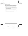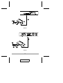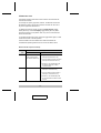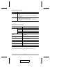
1
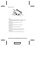
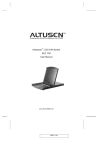
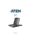
User Manual
KA9250
Read this guide thoroughly and follow the installation and operation
procedures carefully in order to prevent any damage to the units and/or
any devices that connect to them.
This package contains:
M
M
M
M
1 KA9250 KVM Extender Module
1 Power Adapter
1 User Manual
1 Quick Start Guide
If anything is damaged or missing, contact your dealer.
© Copyright 2003 ATEN® International Co., Ltd.
Manual Part No. PAPE - 1226-1AX
Printed in Taiwan 01/2003
All brand names and trademarks are the registered property of their respective owners.
2003-01-17
Note: This equipment has been tested and found to comply with
the limits for a Class B digital device, pursuant to Part 15 of the FCC
Rules. These limits are designed to provide reasonable protection
against harmful interference in a residential installation. This
equipment generates, uses and can radiate radio frequency energy,
and if not installed and used in accordance with the instruction
manual, may cause interference to radio communications.
However, there is no guarantee that interference will not occur in a
particular installation. If this equipment does cause harmful
interference to radio or television reception, which can be
determined by turning the equipment off and on, the user is
encouraged to try to correct the interference by one or more of the
following measures:
M Reorient or relocate the receiving antenna;
M Increase the separation between the equipment and receiver;
M Connect the equipment into an outlet on a circuit different from
that which the receiver is connected;
M Consult the dealer or an experienced radio/television technician
for help.
2003-01-17
Overview
The KA9250 KVM Extender Module allows the KH0116 and KL0116 16
Port High Density KVM Switches to be operated from a remote console
up to 150m away.
The KA9250 module connects to the KH0116 or KL0116’s RJ-45
Remote Console port via industry standard Category 5 cable for a neat
and reliable installation. When a Local and Remote Console are
present, both can access the Switch.
The KA9250 features a custom ASIC to ensure the utmost in reliability
and compatibility, that can also sense the distance to the KH0116 or
KL0116 and automatically adjust the gain to compensate.
Setup is quick and easy - simply plug the remote console components
(keyboard, monitor and mouse) into the KA9250’s Console ports; run
the Cat. 5 cable to the KH0116 or KL0116’s RJ-45 Remote Console
port; plug in the power adapter; and you are ready to go.
Features
M Built-in ASIC for Greater Reliability and Compatibility
M Category 5 Cable to Connect the Remote Unit to the KH0116 or
KL0116 - Up To 150m Away
M Push Button Selection of the Active Console
M High Resolution Video - Up To 1280 x 1024
M Supports VGA, SVGA, and Multisync Monitors
M Local Monitor Supports DDC; DDC2; DDC2B
M Automatic Gain Control - Automatically Adjusts Signal Strength to
Compensate for Distance
-1-
2003-01-17
Installation Requirements
Remote Console
M A VGA, SVGA, or Multisync monitor capable of the highest
resolution that you will be using on any computer in the installation
M A PS/2 style keyboard
M A PS/2 style mouse
Note: 1. If you connect a DDC type monitor to the Local unit, the
monitor that connects to the Remote unit must be able to
support the highest video resolution that the DDC monitor
can provide.
2. You must use the same brand and model of mouse on both
the local and remote units.
Cable
Category 5 cable is the minimum required to connect the KA9250 to the
KH0116 or KL0116. Cable of a lesser standard will result in degrading
the video signal. For best performance, we strongly recommend
Category 5 cable.
-2-
2003-01-17
Rear View
1
R
PO
WE
K
LIN
9V
AC
C
P
U
I/
O
E
T
O
M
E
R
2
3
6
4
5
1. LEDs
The KA9250 has two LEDs (Power and Link) to indicate the operating
status of the Local and Remote units (see p. 7, for details).
2. Mouse Port
The remote PS/2 mouse plugs into this connector.
3. Keyboard Port
The remote PS/2 keyboard plugs into this connector.
4. Monitor Port
The remote monitor plugs into this connector.
5. Remote I/O
The Category 5 cable that connects back to the KH0116 or
KL0116’s Remote Console port plugs into this connector.
6. Power Jack
The cable from the AC Power Adapter plugs into this jack.
-3-
2003-01-17
Installation
All installation involves is plugging cables into their appropriate ports.
Refer to the diagrams on the next page as you perform the following
steps:
1. Plug the keyboard, monitor, and mouse cables for the remote
console devices into their ports on the Console side of the KA9250.
2. Plug either end of the Category 5 cable into the KA9250’s Remote
I/O port. Plug the other end of the cable into the Remote Console
port of the KH0116 or KL0116.
3. Plug the power adapter (supplied with the KA9250) into an AC
source; plug the adapter’s power cable into the KA9250’s Power
Jack.
4. Power up your KH0116 or KL0116 installation according to the steps
given in the Installation section of its User Manual.
-4-
2003-01-17
2
LINK
PO
WER
3
9V
AC
C
P
U
I/
O
E
T
O
M
E
R
1
KH0116
2
LIN
K
PO
WER
9V
AC
C
P
U
I/
E
T
O
M
E
R
O
3
1
KL0116
-5-
2003-01-17
Operation
The default operating environment is for both the Local and Remote
consoles to be active.
For security and privacy purposes, however, the Remote console can
be disabled so that it cannot have access to the KH0116 / KL0116 or
any of the equipment attached to it.
To disable the Remote console, press the Disable Remote toggle
button (KH0116), or the LCD Display toggle button (KL0116) until it
clicks and locks into the In position. Now, only the Local Console has
access to the Switch.
To reenable the Remote console, press the toggle button again, so that
it clicks and returns to the Out position.
The KH0116/KL0116 and KA9250 have LEDs that indicate the
Local/Remote operating status as shown in the two tables, below:
KH0116 / KL0116 (Local Console):
Operating Mode
LED
Local
Local
Auto
Lights to indicate that the
local console is active
(the Remote LED is out).
1. Lights when the local console is
active (the Remote LED is out)
2. Turns off when the remote console is
active (the Remote LED turns on)
3. Flashes on and off alternately with
the Remote LED when neither
console is active.
Remote
The LED is Off.
1. Lights when the remote console is
active (the Local LED is out)
2. Turns off when the local console is
active (the Local LED turns on)
3. Flashes on and off alternately with
the Local LED when neither console
is active.
-6-
2003-01-17
KA9250 (Remote Console):
LED
Indication
Power
1. Lights steadily to indicate that the connection to the Local Unit
is ok.
2. Flashes when there is a problem with the connection to the
Local Unit.
Link
1. Lights when the remote console is active.
2. Is Off when the local console is active.
3. Is Off when there is a problem with the connection to the
Local Unit.
Specifications
Function
Connectors
KA9250R
Keyboard
1 x 6 pin mini-DIN female
Mouse
1 x 6 pin mini-DIN female
Monitor
1 x 15 pin HDB female
Unit To Unit
8P8C Jack
LEDs
1 Power On
1 On Line
Cable Length
150m [500’] (max.)
Video Resolution
1280 x 1024
DDC; DDC2; DDC2B*
Power Consumption
AC 9V 4.0W (max.)
Housing
Metal
Weight
220 g
Dimensions (L x W x H)
100 x 80 x 35 mm
* DDC, DDC2, and DDC2B support is for the Local monitor only.
-7-
2003-01-17
Troubleshooting
Symptom
No Video
Action
Make sure that all cables are securely plugged into their
sockets.
Limited Warranty
IN NO EVENT SHALL THE DIRECT VENDOR’S LIABILITY EXCEED THE PRICE
PAID FOR THE PRODUCT FROM DIRECT, INDIRECT, SPECIAL, INCIDENTAL,
OR CONSEQUENTIAL DAMAGES RESULTING FROM THE USE OF THE
PRODUCT, DISK, OR ITS DOCUMENTATION.
The direct vendor makes no warranty or representation, expressed, implied, or
statutory with respect to the contents or use of this documentation, and especially
disclaims its quality, performance, merchantability, or fitness for any particular
purpose.
The direct vendor also reserves the right to revise or update the device or
documentation without obligation to notify any individual or entity of such revisions,
or update. For further inquiries, please contact your direct vendor.
-8-
2003-01-17