1
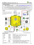
ALLEN&HEATH
GR2
Audio Zone Mixer
Safety Instructions ............... 3
S
Soouunndd C
Coonnttrraaccttoorr A
Apppplliiccaattiioonnss
Introduction ......................... 4
Welcome to the GR2 ........... 5
Features............................... 6
66 M
Miiccrroopphhoonnee IInnppuuttss
Audio Signal Paths .............. 8
System Function.................. 9
33 S
Stteerreeoo LLiinnee IInnppuuttss
Connecting Power ............... 9
11 S
Stteerreeoo,, 11 M
Moonnoo ZZoonnee
A
Assssiiggnnaabbllee A
Auuxx O
Ouuttppuutt
Front Panel .......................... 10
Rear Panel ........................... 11
Configuration Settings......... 12
Zone Remote Wired ............ 14
PL-12 Wall Plate................... 15
R
Reem
moottee C
Coonnttrrooll
Utility Remote ...................... 16
Installation............................ 17
IInnssttaalllleerr C
Coonnffiigguurraabbllee
Applications ......................... 18
Specification ........................ 20
Configuration Sheets........... 22
USER GUIDE
INSTALLATION
Publication AP6320
Limited One Year Warranty
This product has been manufactured in the UK by Allen & Heath Limited and is
warranted to be free from defects in materials or workmanship for a period of one
year from the date of purchase by the original owner.
To ensure a high level of performance and reliability for which this equipment has
been designed and manufactured, read this user guide before operating. In the
event of a failure, notify and return the defective unit to Allen & Heath Limited or
its authorised agent as soon as possible for repair under warranty subject to the
following conditions
Conditions Of Warranty
1. The equipment has been installed and operated in accordance with the
instructions in this user guide
2. The equipment has not been subject to misuse either intended or accidental,
neglect, or alteration other than as described in the user guide or service
manual, or approved by Allen & Heath.
3. Any necessary adjustment, alteration or repair has been carried out by Allen
& Heath or its authorised agent.
4. The defective unit is to be returned carriage prepaid to Allen & Heath or its
authorised agent with proof of purchase.
5. Units returned should be packed to avoid transit damage.
In certain territories the terms may vary. Check with your Allen & Heath agent for
any additional warranty which may apply.
This product complies with the European Electromagnetic Compatibility
directives 89/336/EEC & 92/31/EEC and the European Low Voltage
Directives 73/23/EEC & 93/68/EEC.
NOTE: Any changes or modifications to the unit not approved by Allen & Heath could void the
compliance of the unit and therefore the user’s authority to operate it.
GR2 User Guide AP6320 Issue 1
Copyright © 2005 Allen & Heath Limited. All rights reserved
Whilst we believe the information in this guide to be reliable we do not assume responsibility for
inaccuracies. We also reserve the right to make changes in the interest of further product
development.
Allen & Heath Limited
Kernick Industrial Estate,
Penryn, Cornwall, TR10 9LU, UK
http://www.allen-heath.com
2
GR2 User Guide
Important Safety Instructions
READ THESE INSTRUCTIONS BEFORE PROCEEDING
This symbol, wherever it appears, alerts you to the presence of uninsulated
dangerous voltage inside the enclosure that may be sufficient to constitute a
risk of electric shock.
This symbol, wherever it appears, alerts you to important operating and
maintenance instructions in the accompanying literature.
CAUTION
ATTENTION: RISQUE DE CHOC ELECTRIQUE – NE PAS OUVRIR
Read instructions: Read and retain these safety and operating instructions for future reference.
Heed all warnings printed here and on the appliance. Follow the operating and user instructions
printed in this user guide.
Do not remove cover: This appliance contains no user serviceable parts inside. Operate the
appliance with its cover correctly fitted.
Power sources:
Connect the appliance to a mains power outlet only of the type described in
this user guide and marked on the rear panel. Use the power cord with sealed mains plug
appropriate for your local mains supply as provided with the console. If the provided plug does not fit
into your outlet consult your service agent for assistance.
Power cord routing:
Route the power cord so that it is not likely to be walked on, stretched
or pinched by items placed upon or against it.
Grounding:
Do not remove or tamper with the ground connection in the power cord. Do not
defeat the grounding and polarisation means of the power cord plug. A polarised plug has two
blades with one wider than the other. A grounding type plug has two blades and a third grounding
prong. The wide blade or the third prong are provided for your safety. When the provided plug does
not fit your outlet, consult an electrician for replacement of the obsolete outlet.
WARNING: This apparatus must be earthed.
Water and moisture: To reduce the risk of fire or electric shock do not expose this appliance
to rain or moisture. Do not place containers of liquids on surfaces where liquid may spill into any
openings. Do not expose the appliance to dripping or splashing.
Ventilation:
The appliance should be situated so that its location or position does not interfere
with its proper ventilation. Do not obstruct its ventilation openings. If the appliance is to be operated
in a rack or other furniture ensure that it is constructed to allow adequate ventilation.
Heat: Do not locate the appliance in a place subject to excessive heat or direct sunlight as this
could be a fire hazard. No naked flame sources such as lighted candles should be placed on or near
the appliance.
Servicing: Switch off the equipment and unplug the power cord immediately if it is exposed to
moisture or spilled liquid, if objects have fallen into the openings, if the power cord or plug have
become damaged, if the appliance has been dropped, during lightning storms, or if smoke, odour or
noise is noticed. Refer servicing to qualified technical personnel only.
Installation: Install and use the appliance in accordance with the instructions printed in this user
guide. Do not connect the output of power amplifiers directly to this appliance.
connectors and plugs only for their intended purpose.
Use audio
Operating environment Protect the appliance from excessive dirt, dust, smoke, ash, heat and
vibration when operating and storing.
Cleaning Clean the appliance only with a dry, soft cloth.
GR2 User Guide
3
Introduction
This User Guide provides a quick reference to the installation and operation of the GR2 audio
zone mixer. We refer to two types of user in this guide: The Installer configures the unit for the
application and is assumed to have technical knowledge in audio system interconnection and
setup. The Operator is the day to day user of the unit and does not require technical knowledge.
This guide provides technical information for the installer. A Configuration Sheet is included at the
rear of this guide so that the installation settings and instructions for the operator may be logged.
The GR2 offers many configuration possibilities to satisfy the custom requirements of a multitude
of architectural and utility sound applications. To take advantage of this capability, we
recommend that the installer studies the system block diagram to fully understand its signal flow
and control possibilities.
Important Mains plug wiring instructions.
The console is supplied with a moulded mains plug fitted to the AC mains power lead. Follow the
instructions below if the mains plug has to be replaced. The wires in the mains lead are coloured
in accordance with the following code:
TERMINAL
WIRE COLOUR
European
USA/Canada
L
LIVE
BROWN
BLACK
N
NEUTRAL
BLUE
WHITE
E
EARTH GND
GREEN & YELLOW
GREEN
The wire which is coloured Green and Yellow must be connected to the terminal in the plug which
is marked with the letter E or with the Earth symbol. This appliance must be earthed.
The wire which is coloured Blue must be connected to the terminal in the plug which is marked
with the letter N.
The wire which is coloured Brown must be connected to the terminal in the plug which is marked
with the letter L.
4
GR2 User Guide
Welcome to the GR2
The GR2 is a compact 9 in 4 out 1U rack mount analogue zone mixer with 6 mic
and 3 stereo line inputs, two zone outputs (1 stereo, 1 mono), and an assignable
mono aux output.
It is configured by the installer for a variety of applications by setting front panel
DIP switches and presets. These are accessible by removing a cover plate
which protects the settings during day-to-day operation, and can be used to
mount a custom ident label. Simple controls such as mute, source select and
level are available to the operator, or can be plugged to lock their function. A
combination of XLR, phono and Phoenix screw terminal connections is provided
to conveniently suit both the freestanding and installed applications. Additional
connections are provided to input external paging and alarm audio signals, and
to expand the number of mics beyond 6 by linking GR2 units. Exceptional
capability is provided with functions such as paging, mic priority, music
override, alarm input, and independent mic and zone EQ.
Each input channel and zone output is provided with its own level control and
signal meter. Level and/or source selection for each zone can be configured for
local front panel or remote control using industry standard 10V control. The
installer can make simple potentiometer/rotary switch wall plates, interface with
third party systems such as AMX, or use the Allen & Heath PL12 wall plates with
or without the optional PL-5 infra-red controller. A utility socket allows remote
control of page selection, mic muting and priority, and alarm trigger.
Stereo and mono zones each with local or remote source selection and level…
Aux output for additional zone, recording, sub bass feed, mic expander…
Configure as 6 mic / 3 stereo line, or 4 mic / 4 stereo line, mic expander…
Source select or mix all operating modes…
Page ducking, music override, mic priority, alarm override…
Remote control…
GR2 User Guide
5
Features
mic
mute
ALLEN&HEATH
mic
priority
mic 1
mic 2
mic 3
mics
mic 4
mic 5
1 2
GR2
music 4
mic 6
music 1
1 2
music 2
1 2
music 3
music
mute
alarm
music 3
music
mute
alarm
mono
< source >
mono
< source >
zone 1
zone 2
< source >
1 2
1 2
AUDIO ZONE MIXER
mic
mute
ALLEN&HEATH
mic
priority
mic 1
mic 2
mics
mic 3
mic 4
mic 5
1 2
GR2
music 4
mic 6
music 1
1 2
music 2
1 2
1 2
zone 1
zone 2
< source >
1 2
AUDIO ZONE MIXER
!
phantom pwr
A B C D
on
power on
mic 1 2 34 56
100 - 240V~
47-63Hz ~ 25W MAX
mic enable
E F G H
on
page Z1 Z2
mic1=page
mic priority
pad
pad
gain trim
mic 1
pad
pad
gain trim
mic 3
gain trim
mic 4
CAUTION: RISK OF ELECTRIC SHOCK. DO NOT OPEN. AVIS: RISQUE DE CHOC ELECTRIQUE - NE PAS OUVRIR.
ATTENTION: REMPLACER PAR UN FUSIBLE STRICTEMENT IDENTIQUE EN VALEURS.
Z2
FOR CONTINUED PROTECTION AGAINST RISK OF FIRE
REPLACE FUSE WITH SAME TYPE AND RATING.
FUSE: T1AL
WARNING
pad
gain trim
mic 2
UTILITY REMOTE
ZONE REMOTE
AUX
OUT
pad
gain trim
mic 5
Z1
L
gain trim
mic 6
ZONE OUT
R
music 1
music 2
music 3
+4
+4
+4
-10
-10
-10
music 1 priority
I J K L
G
AUX
+ -
G
Z2
+
-
G
Z1R
+ -
G
Z1L
+
-
50
on
20
mic56=music4
Z2 enable
Z1 enable
long release
level trim
3
L
2
L
R
R
300
200
HPF
MUSIC IN
400
-
MF
+ 180
mic EQ
2k
FREQ
EXPAND IN
1
L
R
music
select
remote enable
M N O P
5k
-
HF
+
on
mix
all
sel
one
zone source
Q R S T
on
Z2 source
Z2 level
Z1 source
Z1 level
aux source
U V W X
-
LF
music
mics Z2
Z1=music+mics
+
zone 1 EQ
G
MIC MIX
+ -
G
PAGE
+ -
G
MIC 2
+ -
G
MIC 1
+ -
G
MIC 6
+ -
G
MIC 5
+ -
G
MIC 4
+ -
G
MIC 3
+ -
HF
+
page mix
mic mix
aux output
100Hz
sub filter
on
follow Z2
follow Z1
MIC 1
THIS APPARATUS MUST BE EARTHED.
ALLEN&HEATH
GR2
MADE IN THE UK BY ALLEN & HEATH LIMITED
( R - MUSIC 4 - L )
6 (4) mic / line inputs
Mic 1 balanced Phoenix terminal plug and XLR, 2-6 Phoenix
Selectable +15V phantom power (mic 1,2,34,56)
Gain trims and pad switches protected behind front cover plate
Mic or line level capability (-60dBu to +20dBu signal sensitivity)
Mic priority for chairman override with panel and remote control
Mic priority on mic 1 (or 2 if a paging mic is configured on mic 1)
Configurable as 6 mic + 3 stereo or 4 mic + 4 stereo inputs
Mic / line inputs 5/6 can be configured as stereo music input 4
Music 4 input balanced on Phoenix plug for long cables runs
3 band mic EQ with swept HPF, swept MF and shelf HF
Mic expander input
0dBu line level balanced on Phoenix plug
Aux output can be configured as a 0dBu mic expander send
Dedicated paging channel with 2 sources
Configurable from Mic / line 1 input, and/or
Balanced page input on Phoenix plug (ext paging or alarm)
Preset page channel EQ for speech intelligibility
Ducking of zone program on presence of page mic signal
External switching to enable paging to zone 1 and/or zone 2
Aux output can be configured as a page feed to other units
3 (4) stereo line music inputs
+4/-10 level setting protected behind front cover plate
One-at-a-time or mix all source selection
Independent source selection for each zone
Panel or remote level and/or source selection
Music source mute switch
Stereo input 1 configurable as priority input (jukebox, adverts)
Overrides other selections on presence of audio signal
Short or long priority release time
6
GR2 User Guide
2 zone outputs, one stereo one mono
0dBu, duplicated on RCA phono and balanced Phoenix
Zone 1 configurable as music only or music+mics mix
Zone 2 configurable as mics, music or music+mics mix
VCAs for page ducking, alarm override and remote level control
2 band zone 1 music EQ with shelving LF and HF
Zone 1 stereo/mono switch
Mono Aux output
0dBu, duplicated on RCA phono and balanced Phoenix
Configurable as page out, mic mix, zone 1 (mono) or zone 2
Switchable low pass filter for sub bass application
Front panel controls
9 input channels with level and signal/peak meters
Input level control provides +6dB boost
2 zones with level, source <> select and signal/peak meters
Source active indicators for each zone
Mic priority, mic mute, music mute and alarm active indicators
Zone Remote RJ45
CAT5 cable to connect zone 1 and/or zone 2 remote
Standard 0-10V DC level control, 0V=off, +10V=on
0-10V stepped for remote selection of up to 4 sources plus off
Provides +10V for reference and for remote circuit power
Many remote control possibilities including:
Level control using hard wired potentiometer
Resistive ladder source select using hard wired rotary switch
Resistive ladder source select using 2-pole switches with LEDs
Third party control (AMX/Crestron) using 10V interface
Optional PL-12 wall plate with IR and extended functions
PL-5 hand held IR remote works with PL-12
Utility Remote RJ45
Logic control – switch to ground = active
Provides +10V for remote circuit power
Interfaces with third party and custom systems
Mute control for mic mix
Priority mic override switching
Alarm switch mutes all except page channel
External page to zone 1, 2 enable
Connections
Phoenix screw terminal plugs for pre-wired installation
Standard XLR and RCA phono connectors for plug-and-play
RJ45 for CAT5 cable connection to remotes
Universal 100-240V.AC IEC mains input
Mechanics
Compact 1U rack or desk mount
Removable front plate to access installer configuration settings
Dip switches letter coded for installer convenience
Level controls can be removed and plugged for protection
Bolt-on rack ears provided for 19” rack mounting
Plastic feet fitted for desk mounting
No need to remove the cover, all settings accessible on front
GR2 User Guide
7
Audio Signal Paths
Simplified block diagram
GR2 AUDIO ZONE MIXER
EXPAND
PL-12 WALL PLATE
PAGE MIX
EXT PAGE IN
PAGE EQ
MIC MIX
10V LOGIC
MIC2
MIC1
UTILITY REMOTE
1
Z1 PAGE ENABLE
Z2 PAGE ENABLE
MIC MUTE
MIC PRIORITY
ALARM OVERRIDE
MIC PRIORITY
MIC4
ZONE REMOTE
PL-5 IR CONTROLLER
PAGE MIC
MIC3
Z1 SOURCE SELECT
Z1 LEVEL
Z2 SOURCE SELECT
Z2 LEVEL
2
3
4
5
1
2
10
5
AUX ZONE2
11
3
12
13
4
14
6
7
8
PL-5
9
MIC MIX
AUX
MIC EQ
MIC6
MIC5
PAGE MIX
PHANTOM POWER
GAIN / PAD
MIC MUTE
L
MUSIC1
R
1
SUB EQ
ZONE1
DUCKING
AUX
ZONE2
LEVEL
SOURCE
< SELECT >
ZONE2
MIC MIX
MIC5/6, MUSIC4
MUSIC PRIORITY
SOURCE
MICS
MUSIC
PAGE
ZONE2 MIX
ZONE1
MONO
2
3
4
L
MUSIC2
R
< SELECT >
MUSIC MUTE
MICS
LEVEL
ZONE1 MIX
1
2
L
MUSIC3
R
3
4
PAGE
STEREO
ZONE1 EQ
L
ZONE1
R
MONO / STEREO
LINE +4/-10
REMOTE CONTROL
Page mix - Overrides the music/mic selection. The input is from the external
page input and/or from mic 1 if it is configured as a paging mic. The page mix
EQ provides high pass and low pass filters tuned for paging speech. The mix
routes directly to the zone outputs and is not affected by the output level front
panel or remote controls. Signal detected on the page mix causes ducking of
any page enabled zone.
Mic mix - The performance or conference mic mix. Depending on the
configuration, the mic mix may comprise 3, 4, 5 or 6 mic inputs being sourced
from mics 1-6, 2-6, 1-4 or 2-4. The mix of mic inputs can be routed to the zones
via the VCAs, or direct to the aux output. A dedicated mic EQ provides a swept
frequency high pass filter, swept frequency peak/dip mid, and shelving high
frequency cut/boost tuned to deal with typical live performance or conference
microphone mixing.
Music mix - An independent mix of the music sources for each zone. Each
has operator controllable music source selection. The number of sources that
can be selected by the operator depends on the configuration, either 2, 3 or 4.
Alternatively, all sources can be permanently mixed together. Music 1 input can
have priority over the other sources for applications such as jukebox or live /
pre-recorded retail announcements. Mics 5/6 can be configured as an
additional ‘music 4’ balanced stereo source. This allows either 6 mic / 3 stereo
music or 4 mic / 4 stereo music capability.
Zone 1 and 2 VCA mixes - The music plus mic mix for each zone. Zone 1
is stereo, zone 2 is mono. Routed through a VCA, the mix is overridden during
paging or when the alarm input is triggered. The mic mix can be added to the
pre-VCA music mix. Zone 1 has a 2-band EQ and mono switching.
Aux mix - An independent mono output which can be sourced from any
combination of the page mix, mic mix, post-level zone 1 or zone 2 mix.
Applications include routing the page mix only to create a single paging source
to daisy chain through other GR2 units, routing mic mix only to expand the
number of mics to a second GR2, feeding a conference recorder, or creating a
mono sum and filtered sub bass mix to compliment the zone 1 stereo output.
8
GR2 User Guide
System Function
A B C D
GR2 AUDIO ZONE MIXER
MIX
+
-
PAGE 1 2 3456
PAGE EQ
+
EXPAND
Detailed block diagram
PHANTOM POWER
PAD
MIC2
+
-
MIC1
+
-
MIC4
PK
sig
+
-
MIC3
+
PK
sig
TRIM
PAD
MIC6
+
-
MIC5
PK
sig
TRIM
PAD
( R - MUSIC 4 - L )
G
+
-
1
2
3
4
HPF MF
F
HF
5
11
13
PL-
9
5
VCA
0V
MIC EQ
CAT5
UTILITY REMOTE
ZONE 2 MIX
Z1
LEVEL
PAGE
S
+
Z2
+
Z1
J
ZONE 1,2 REMOTE
PAGE Z1 ENABLE
PAGE Z2 ENABLE
MIC MUTE
MIC PRIORITY
ALARM MUTE
Z2
Z2
MUTE
CUSTOM
WIRED
REMOTE
MIC MUTE
MUSIC 4
I
REMOTE
LOCAL
MUSIC MIX
O
REMOTE 0-10V
LEVEL
Z2
AUX
PAGE
DUCK
V
+
SUB
EQ
MICS
DUCKING
SIGNAL DETECT
LEVEL
AUX MIX
U
MUTE
Z1
Z2 OUT
AUX
SOURCE
LEVEL
T
Z1 SOURCE SELECT 0-10V
Z1 LEVEL 0-10V
Z2 SOURCE SELECT 0-10V
Z2 LEVEL 0-10V
PK
sig
F
L
MUSIC 1
PRIORITY
Z2
FOLLOW
Z2
-20dB
FOLLOW
Z1
MUSIC MUTE
X
W
+
L
MUSIC 2
R
10
12
14
6
LEVEL
PK
sig
SOURCE
1
2
3
4
5
8
LEVEL
LEVEL
+4/-10
+10V
7
H
LONG RELEASE
L
MUSIC 1
R
MIC MIX
MIC PRIORITY
LEVEL
MIC MIX
+
+4/-10
LEVEL
LEVEL
MUSIC PRIORITY
SIGNAL DETECT
PK
sig
Z2
Z1
REMOTE
PK
sig
TRIM
PAD
Z2
Z1
MIC1 PAGE
PL-5 IR CONTROLLER
TRIM
PAD
LEVEL
PL-12 WALL PLATE
PK
sig
TRIM
PAD
WALL PLATE DISABLE
WIRING OPTIONS
PK
sig
TRIM
MIC1
Z2 FOLLOW Z1
(ROOM COMBINING)
PAGE MIX
+
-
FILTER ON
Z2
PK
sig
MIC MIX
+
+4/-10
LF
LEVEL
L
MUSIC 3
R
PAGE
L
Z1 OUT
R
ZONE 1 MIX
Z1
HF
Z1
Z1
MONO
R
REMOTE
LOCAL
PK
sig
E
Z1 OUT
+
1L
Z2
SOURCE SELECT
< Z1 >
< Z2 >
Z1
M
Z2
P
REMOTE
Q
MIX ALL (SELECT OFF)
K
+
+
ZONE 1 EQ
1R
DUCK
MUSIC 1
PRIORITY
LEVEL
MUTE
REMOTE ALARM INPUT
N
REMOTE LEVEL 0-10V
Configuration settings - The system block diagram shows the many
configuration possibilities to satisfy the unique requirements of each installation.
The DIP switches are labeled with letters for easy identification and logging
using the configuration sheet provided at the rear of this guide.
Mic priority - When switched, all mics except mic 1 are turned off. Note that
mic 2 becomes the priority mic if mic 1 is configured for paging. In this case,
the paging mic 1 is not affected by the priority switch.
Music priority - If configured, the pre-level music 1 signal is detected. If it
exceeds a -20dB threshold the Z1 and Z2 FETs are turned off to mute the
currently selected music source. Release time can be set to short or long.
Paging - Overrides any page enabled zone by ducking the VCA by 20dB
when page signal is detected.
Remote control - The Zone remote may be custom wired to potentiometers
and switches or connected to the PL-12 wall plate using standard CAT5 cables
as shown here. Other functions may be hard wired to the Utility remote.
GR2 User Guide
9
Front Panel – Operator Controls
8
7
1
ALLEN&HEATH
mic
mute
mic
priority
9
6
mic 1
mic 2
mic 3
mics
14
mic 4
mic 5
1 2
GR2
music 4
15
13
mic 6
music 1
1 2
1 2
music 2
1 2
music 3
music
mute
10
16
alarm
mono
< source >
zone 1
< source >
12
zone 2
1 2
AUDIO ZONE MIXER
3
5
2
17
4
KNOB
PRESET
11
PLUG
1. Rack ears
9. Mic mix selected indicators
These are supplied fitted ready for 19” rack or furniture
mounting. For desk top operation they may be removed
using a T10 Torx screwdriver.
Lights when the mic mix has been configured to route to
the zone. One for each zone.
2. Feet
Use the < and > keys to scroll through the available
music sources for each zone. They are disabled if
remote control is configured.
These are supplied fitted ready for desk top operation. If
they need to be removed for installation into a 1U rack
space then use a small slotted screwdriver to lever out
the plastic rivet from the centre of each foot.
3. Power on indicator
Lights to indicate that mains power is applied to the unit.
4. Cover plate
A cover plate protects the configuration settings and
provides a space for fitting a custom label to identify the
control functions. Use a 2mm Allen key to remove the
three hex head screws before lifting off the plate to
access the configuration switches and trimmers.
5. Input level controls
Rotary controls to adjust the levels of the microphone
and music input channels from fully off to +6dB boost.
0dB unity position is 3 o’clock. If required, the knobs
may be pulled off and the settings protected for day-today operation using the plastic hole plugs provided.
6. Input signal meter
A 2-colour indicator lights green when a signal level
above -14dB is detected, and red for signals above
+14dB. The input gain should be reduced if the meter
consistently lights red. The signal is pre level control.
7. Mic mute switch
Turns off the mic mix channel. The red indicator lights
when the mics are muted either by this switch or remote
control. This does not affect the paging mic.
8. Mic priority switch
Turns off all mics except mic 1 (or 1 and 2 if mic 1 has
been configured for paging). Use this function for
chairman or MC override using mic 1 (2). The red
indicator lights when priority is selected either by this
switch or remote control. The priority function does not
affect the paging mic.
10
10. Source select keys
11. Zone level controls
Rotary controls to adjust the output level of each zone
from fully off to fully on (0dB unity gain). Disabled if
remote control is configured. Does not affect the page
mix level which is routed to the zone after the level
control. If required, the knobs may be pulled off and the
settings protected using the plastic hole plugs provided.
12. Output signal meter
A 2-colour indicator lights green when a signal level
above -14dB is detected, and red for signals above
+14dB. The signal is post level control.
13. Music 1-3 source selected indicators
Light when the associated music source is selected for
the zone. All light if ‘mix all’ mode is configured.
14. Music 4 source selected indicator
Lights when mic 5/6 has been configured as music
source 4, and has been selected using the panel or
remote source select keys or mix all function.
15. Music mute switch
Turns off the current music source selection. The red
indicator lights when the source is muted by the switch.
16. Alarm indicator
The red indicator lights when the zones have been
muted by an external trigger wired to the utility remote
socket. Does not affect the paging channel which
remains active for paging or evacuation messages.
17. Zone 1 mono switch
Sums the stereo zone L and R signals for mono
operation.
GR2 User Guide
Rear Panel - Connections
2
1
3
10
CAUTION: RISK OF ELECTRIC SHOCK. DO NOT OPEN. AVIS: RISQUE DE CHOC ELECTRIQUE - NE PAS OUVRIR.
ATTENTION: REMPLACER PAR UN FUSIBLE STRICTEMENT IDENTIQUE EN VALEURS.
Z2
FOR CONTINUED PROTECTION AGAINST RISK OF FIRE
REPLACE FUSE WITH SAME TYPE AND RATING.
100 - 240V~
47-63Hz ~ 25W MAX
FUSE: T1AL
UTILITY REMOTE
ZONE REMOTE
WARNING
9
Z1
L
AUX
OUT
11
ZONE OUT
R
10
G
AUX
+ -
G
Z2
+
-
G
Z1R
+ -
G
Z1L
+
-
7
3
L
2
L
R
R
MUSIC IN
EXPAND IN
1
L
R
6
5
4
G
MIC MIX
+ -
G
PAGE
+ -
G
MIC 2
+ -
G
MIC 1
+ -
G
MIC 6
+ -
G
MIC 5
+ -
G
MIC 4
+ -
G
MIC 3
+ -
MIC 1
THIS APPARATUS MUST BE EARTHED.
ALLEN&HEATH
GR2
( R - MUSIC 4 - L )
MADE IN THE UK BY ALLEN & HEATH LIMITED
2
13
12
11
G
Do not plug network or other nonrelated RJ45 cables into these sockets.
Z1R
+ -
9
G
Z1L
+
-
8
5
G
MIC 4
+ -
G
MIC 3
+ -
Shorting plugs for
unused inputs
1. Power ON/OFF switch
7. Mic expander input
This switch is rear panel mounted to prevent accidental
or illegal user operation. Press to switch on or off.
Balanced with +, - and ground connections to feed a
0dBu external line level signal to the mic mix. Plug
another GR2 in to expand the number of mic inputs.
This input is muted when mic priority is active.
To avoid power up thumps, make sure power
amplifiers are turned on last and turned off first.
2. Mains input IEC connector
Check that your local mains supply matches
that marked on the rear of the unit. Check that
the mains IEC plug is correctly seated.
3. Mains fuse
Replace only with the type and value marked on
the rear panel. Turn the unit off and unplug the
power cord before removing the fuse.
4. Mic 1 XLR input
The mic 1 input is duplicated on both XLR and Phoenix
screw terminal plug for installer convenience. This is
convenient for pre-wiring custom cables or using a
standard XLR mic cable. Only one connection should
be used. The input is balanced pin2=+ and can be
configured to provide phantom power.
5. Mic 1-6 Phoenix plug inputs
The inputs are balanced, each with +, - and ground
connections. Plug mic 1 into either the Phoenix or the
XLR, not both. Phantom power can be configured to a
combination of mics 1, 2, 3+4, 5+6. Line level sources
may be used by setting the front panel configuration pad
switches. Sensitivity can be adjusted to accept signals
within the range -60dBu to +20dBu. Mics 5/6 may be
configured as another stereo mic or line music source
with balanced input suitable for long cable connection.
6. External Page input
Balanced with +, - and ground connections to input a
0dBu external line level signal to the page mix. This
mixes with mic 1 if it has been configured as a paging
mic. Use with an external source such as paging or prerecorded evacuation / safety message.
GR2 User Guide
8. RCA phono music inputs
Unbalanced line level stereo inputs for connection to
music and other stereo sources. Sensitivity may be
configured for +4dBu or -10dBV operation. To prevent
unnecessary signal crosstalk, plug the RCA shorting
plugs provided into any inputs which are not being used.
9. Zone 1 L and R output
Stereo zone 1 output is available on balanced Phoenix
and unbalanced RCA phono plugs. Both may be used
at the same time to split the signal to two different
destinations. Nominal level is 0dBu with +20dBu max..
10. Zone 2 output
Mono zone 2 output is available on balanced Phoenix
and unbalanced RCA phono plug. Both may be used at
the same time to split the signal to two different
destinations. Nominal level is 0dBu with +20dBu max.
11. Aux output
Mono aux output is available on balanced Phoenix and
unbalanced RCA phono plugs. Both may be used at the
same time to split the signal to two different destinations.
Nominal level is 0dBu with +20dBu max.
12. Zone remote
Allows daisy chain connection to Allen & Heath PL-12
wall plates or custom wired or third party remote panels
to control zone 1 and 2 levels and source selections.
Standard RJ45 plugs and CAT5 cable may be used.
13. Utility remote
Allows connection to custom wired or third party
controllers for remote page enable, mic mute and
priority, and alarm trigger. Standard RJ45 connectors
and CAT5 cable may be used.
11
Front Panel – Configuration Settings
ALLEN&HEATH
mic
mute
mic
priority
mic 1
mic 2
mic 3
mics
1 2
GR2
mic 4
mic 5
music 4
mic 6
1 2
music 1
1 2
music 2
1 2
music 3
music
mute
alarm
mono
< source >
zone 1
< source >
To access the configuration settings remove the 3x M3 hex screws
securing the front cover plate. Use the 2mm Allen key provided.
zone 2
1 2
AUDIO ZONE MIXER
!
phantom pwr
A B C D
on
mic enable
E F G H
music 1 priority
I J K L
on
mic 1 2 34 56
on
page Z1 Z2
mic1=page
mic priority
mic56=music4
music
select
remote enable
M N O P
on
Z2 enable
Z1 enable
long release
Z1 source
Z1 level
mix
all
sel
one
zone source
Q R S T
Z2 source
Z2 level
aux source
U V W X
on
on
music
mics Z2
Z1=music+mics
page mix
mic mix
DIP switch settings
Up = ON. Factory default =all switches off.
A
Phantom power mic 1
Switches phantom power to mic 1.
B
Phantom power mic 2
Switches phantom power to mic 2.
C
Phantom power mic 3&4 Switches phantom power to mic 3 and 4.
D
Phantom power mic 5&6 Switches phantom power to mic 5 and 6.
follow Z2
follow Z1
Notes on using phantom power: When enabled, +15V DC phantom power is switched to the +
and – mic input connections. Use only with balanced microphones and cables. To avoid audible
thumps, turn the mic level off before changing the setting, and before plugging the mic cables.
E
Page enable zone 1
The page mix is routed and ducks zone 1 output.
F
Page enable zone 2
The page mix is routed and ducks zone 2 output.
G
Mic 1 = paging
Routes mic 1 to the page mix instead of the mic mix.
H
Mic priority enable
Enables the panel and remote priority switch function.
Notes on paging and mic priority: The page signal is not affected by the zone level control.
When signal is present, the zone mix is ducked by 20dB. When mic 1 is set for paging, it is
removed from the mic mix and mic 2 becomes the priority mic.
I
Mic 5/6 = music 4
Mic/line 5/6 is routed to the music selector instead of the mic mix.
J
Music priority release
Hold time after the music 1 signal stops. Short=2sec, long=12sec.
K
Priority enable zone 1
Enables the music 1 priority override function in zone 1.
L
Priority enable zone 2
Enables the music 1 priority override function in zone 2.
Notes on music priority: When enabled, the music 1 source is routed permanently to the zone.
Presence of music 1 audio signal overrides (mutes) the current source selection.
12
M
Remote source zone 1
Remote source control enabled. The panel <> 1 switches are disabled.
N
Remote level zone 1
Remote level control enabled. The panel level control 1 is disabled.
O
Remote level zone 2
Remote source control enabled. The panel <> 2 switches are disabled.
P
Remote source zone 2
Remote level control enabled. The panel level control 2 is disabled.
Q
Mix all sources
All music sources are mixed together. Source <> selection is disabled.
R
Add mics to zone 1
Zone 1= music only (switch off), or music+mic mix (switch on).
S
Mics to zone 2
Add mics to zone 2 output (independent of the page mix).
T
Music to zone 2
Add music sources to zone 2 output.
U
Page mix to aux
Adds the page mix to the aux output.
V
Mic mix to aux
Adds the mic mix to the aux output.
W
Zone 1 mix to aux
Adds the zone 1 mix to the aux output. Sums L and R into mono.
X
Zone 2 mix to aux
Adds the zone 2 mix to the aux output.
GR2 User Guide
mic
mute
ALLEN&HEATH
mic
priority
mic 1
mic 2
mic 3
mics
mic 4
mic 5
music 4
1 2
GR2
mic 6
music 1
1 2
music 2
1 2
music
mute
music 3
1 2
alarm
mono
zone 1
< source >
zone 2
< source >
1 2
AUDIO ZONE MIXER
!
phantom pwr
A B C D
mic enable
E F G H
on
power on
on
page Z1 Z2
mic1=page
mic priority
mic 1 2 34 56
pad
pad
gain trim
mic 2
pad
pad
gain trim
mic 3
gain trim
mic 4
pad
pad
gain trim
mic 1
pad
pad
gain trim
mic 1
gain trim
mic 2
pad
gain trim
mic 5
gain trim
mic 4
Channel trim settings
music 1 priority
I J K L
50
on
20
mic56=music4
Z2 enable
Z1 enable
long release
level trim
pad
pad
gain trim
mic 3
music 1
music 2
music 3
+4
+4
+4
-10
-10
-10
gain trim
mic 6
300
200
HPF
400
-
MF
2k
+ 180
mic EQ
FREQ
5k
HF
+
on
Z1 source
Z1 level
pad
gain trim
mic 5
music
select
remote enable
M N O P
-
gain trim
mic 6
mix
all
sel
one
Z2 source
Z2 level
zone source
Q R S T
on
aux source
U V W X
-
LF
music
mics Z2
Z1=music+mics
+
zone 1 EQ
HF
+
page mix
mic mix
follow Z2
follow Z1
music 1
music 2
music 3
+4
+4
+4
-10
-10
-10
level trim
Use a small flat bladed screwdriver to set or adjust.
Pad
Switches in a 30dB attenuator pad for the mic input. Use with hot mic or line level sources.
Gain
Adjust from +10 to +60dB gain (-20 to +30dB with pad in). Accepts mic or line signals.
Turn up until the channel LED meter starts to flash red for loud signals, then back off a little.
Music trim
Set the switch to match a high +4dBu or low -10dBV level source (switch pressed in).
50
20
300
200
HPF
aux output
100Hz
sub filter
on
400
-
MF
+ 180
Equaliser (EQ) settings
mic EQ
2k
FREQ
5k
aux output
-
HF
+
-
LF
+
-
zone 1 EQ
HF
+
100Hz
sub filter
Use a small flat bladed screwdriver to adjust.
Note
Start with the EQ set at mid position (flat response, 0dB gain).
Try to make only small adjustments if needed. Cut rather than boost where possible.
Mic HPF
12dB/octave high pass filter to reduce low frequency mic popping and handling noise.
Use FREQ to sweep the cut off frequency from 20Hz (off) to 400Hz.
Start between mid position and 200Hz for typical vocal microphones. Mid position = 100Hz.
Mic MF
Peak/dip equaliser with +/-12dB gain (boost/cut).
Swept frequency range from 180Hz to 5kHz. Mid position = 1kHz.
Use MF to notch out resonant or feedback frequencies, or to improve microphone tone.
Mic HF
Shelving high frequency (treble) equaliser with +/-12dB boost/cut around 12kHz.
Use this to brighten up the sound, or to filter out high frequency noise or ringing.
Zone 1 LF
Shelving low frequency (bass) equaliser with +/-12dB boost/cut around 100Hz.
Use as necessary to tune the response of the stereo zone speakers.
Zone 1 HF
Shelving high frequency (treble) equaliser with +/-12dB boost/cut around 10kHz.
Use as necessary to tune the response of the stereo zone speakers.
Aux 100Hz
12dB/octave low pass (high cut) filter with 100Hz turning point frequency.
Switch this in when using the aux output to feed a sub bass speaker without a crossover.
mic HPF
mic MF
180Hz
20Hz
400Hz
GR2 User Guide
mic HF
5kHz
zone 1 EQ
LF
aux SUB FILTER
HF
100Hz
13
Remote Control – Zone Level and Source Selection
CAUTION: RISK OF ELECTRIC SHOCK. DO NOT OPEN. AVIS: RISQUE DE CHOC ELECTRIQUE - NE PAS OUVRIR.
ATTENTION: REMPLACER PAR UN FUSIBLE STRICTEMENT IDENTIQUE EN VALEURS.
Z2
FOR CONTINUED PROTECTION AGAINST RISK OF FIRE
REPLACE FUSE WITH SAME TYPE AND RATING.
100 - 240V~
47-63Hz ~ 25W MAX
FUSE: T1AL
UTILITY REMOTE
ZONE REMOTE
WARNING
Z1
L
AUX
OUT
ZONE OUT
R
G
AUX
+ -
G
G
Z1R
+ -
Z1L
G +
Z2
+
-
-
3
L
2
L
R
R
MUSIC IN
EXPAND IN
1
L
G
MIC MIX
+ -
MIC 6
G + -
R
G
PAGE
+ -
MIC 5
G + -
G
MIC 2
+ -
MIC 4
G + -
G
MIC 1
+ -
MIC 1
MIC 3
G + -
THIS APPARATUS MUST BE EARTHED.
GR2
( R - MUSIC 4 - L )
MADE IN THE UK BY ALLEN & HEATH LIMITED
Z1 SOURCE
+10V
Z1 LEVEL
0V
Z2 LEVEL
0V
Z2 SOURCE
+10V
ALLEN&HEATH
Voltage control Level and source selection are voltage controlled
using an internal or external +10V DC reference voltage. This
means they can be controlled in many different ways including
custom wired potentiometers, switches and interface circuits, third
party controllers such as AMX or Crestron, or the Allen & Heath PL12 intelligent wall plate with PL-5 infra-red controller option.
WH/GN
GN
WH/OR
BL
WH/BL
OR
WH/BN
BN
1
2
3
4
5
6
7
8
TIA/EIA 568A
1 2 3 45 6 7 8
TIA/EIA 568B
1 2 3 45 6 7 8
WH/OR
OR
WH/GN
BL
WH/BL
GN
WH/BN
BN
LEVEL
SOURCE
0V=off +10V=maximum (0dB)
0V=off, +2V=1, +4V=2, +6V=3, +8V=4
Configure remote control
Set the front panel DIP switches M,
N, O, P to configure which zones and functions to control.
+10Vref
CAT5 wiring
The two zones are wired from one RJ45 socket,
convenient for daisy chaining two zone wall plates using a single
CAT5 cable run. Use standard CAT5 UTP or STP cable terminated
with an RJ45 plug at the GR2 and wired to the circuit at the wall
plate. Wire the circuit according to the RJ45 pin numbers shown
here. If you are using pre-installed cables, note that there are two
CAT5 connection standards, 568A and 568B. The cable colour code
differences are shown in the diagram. Check the pinout first.
LEVEL
4k7 ohm
linear
4
3
2
1
zone 1
Level control Use a linear law rotary potentiometer or a switched
0V
resistor ladder to control the zone level. Use a potentiometer or
ladder value between 2k and 10k ohms. We recommend 4k7 ohms.
Example 1
Source OFF,1,2,3,4
Source selection Use a resistor ladder wired to a rotary or other
type of switch. We recommend 5x 1k ohm resistors wired as shown
in the diagrams here. Wire the switch to the resistors according to
the combination of sources to be used, for example1234, 123, 234,
23. Switching to 0V provides an off position if required. Note that
you may wish to exclude music 1 from the source selection if it has
been configured as the priority source such as a jukebox.
+10Vref
LEVEL
1k ohm
4k7 ohm
linear
SOURCE
8V
1k ohm
6V
1k ohm
4V
1k ohm
2V
1k ohm
4
3
2
1
off
Check the wiring before connecting power Ensure
the CAT5 cable is correctly wired. Check the continuity of all wiring.
Ensure there are no shorts or exposed wire ends.
zone 2
0V
1k ohm
1k ohm
6V
1k ohm
4V
1k ohm
2V
1k ohm
+10Vref
SOURCE
3
2
1
Example 3
Source 2,3
1k ohm
+10Vref
1k ohm
6V
1k ohm
4V
1k ohm
SOURCE
3
2
1k ohm
0V
LEVEL
14
+10Vref
1k ohm
1k ohm
6V
1k ohm
4V
1k ohm
2V
1k ohm
0V
Example 5 Example 6
Set min level Set min/max
+10Vref
Example 4
Push switches
+10Vref
1k ohm
330 ohm
LEVEL
330 ohm
SOURCE
3
2
1
Example 8
Zone 2 follow 1
source and level
0V
Example 7
Stepped level
+10Vref
1k ohm
1k ohm lin
-20dB
1k ohm lin
330 ohm
2k2 ohm
2k2 ohm
2k2 ohm
0V
0V
3
LEVEL
2
1
10V power Do not draw more than 100mA from each
+10V pin. The internal 10V supply is protected against a short
circuit using a resettable fuse. If it trips, turn off the GR2, wait a few
seconds and turn it back on again.
Z1 SOURCE
+10V
Z1 LEVEL
0V
Z2 LEVEL
0V
Z2 SOURCE
+10V
Example 2
Source 1,2,3
1k ohm
6V
1k ohm
4V
LEVEL
SOURCE
3
2
1
2V
1k ohm
off
0V
0V
Z1 SOURCE
+10V
Z1 LEVEL
0V
Z2 LEVEL
0V
Z2 SOURCE
+10V
off
Example 9
Zone 2 follow 1
source only
1
2
3
4
5
6
7
8
SOURCE
8V
1k ohm
6V
1k ohm
4V
1k ohm
2V
1k ohm
1
2
3
4
5
6
7
8
1k ohm
+10Vref
1k ohm
4k7
lin
1k ohm
6V
1k ohm
4V
1k ohm
2V
1k ohm
zone 1
LEVEL
+10Vref
4k7
lin
4k7
linear
zone 2
LEVEL
SOURCE
3
2
1
0V
0V
GR2 User Guide
Remote Control – PL-12 Wall Plate
CAUTION: RISK OF ELECTRIC SHOCK. DO NOT OPEN. AVIS: RISQUE DE CHOC ELECTRIQUE - NE PAS OUVRIR.
ATTENTION: REMPLACER PAR UN FUSIBLE STRICTEMENT IDENTIQUE EN VALEURS.
Z2
FOR CONTINUED PROTECTION AGAINST RISK OF FIRE
REPLACE FUSE WITH SAME TYPE AND RATING.
100 - 240V~
47-63Hz ~ 25W MAX
FUSE: T1AL
UTILITY REMOTE
ZONE REMOTE
WARNING
AUX
OUT
Z1
L
ZONE OUT
R
G
AUX
+ -
G
Z2
+
-
G
Z1R
+ -
G
Z1L
+
-
3
L
2
L
R
R
MUSIC IN
EXPAND IN
1
L
R
G
MIC MIX
+ -
G
PAGE
+ -
G
MIC 2
+ -
G
MIC 1
+ -
G
MIC 6
+ -
G
MIC 5
+ -
G
MIC 4
+ -
G
MIC 3
+ -
MIC 1
THIS APPARATUS MUST BE EARTHED.
ALLEN&HEATH
GR2
( R - MUSIC 4 - L )
MADE IN THE UK BY ALLEN & HEATH LIMITED
CAT5 CABLE
CAT5 CABLE
Z2 FOLLOW Z1
(ROOM COMBINING)
WALL PLATE DISABLE
WIRING OPTIONS
SETUP MENU
PL-12 WALL PLATE
SETUP
OPTIONS
LEVEL
INDICATOR
SOURCE
INDICATOR
SETUP
ITEM
Z2
Z1
Z2
Z1
PL-5 IR CONTROLLER
1
2
3
4
ENTER
SETUP
LEVEL
CONTROL
SOURCE
SELECT
ITEM
SELECT
5
5
1
2
10
11
3
12
13
4
14
6
7
8
PL
-5
9
INFRA-RED
SENSOR
The optional Allen & Heath PL-12 ‘intelligent’ wall plate provides
remote control of zone source selection and level. Full setup and
operating instructions are detailed in the PL-12 user guide. The
following provides an overview of its capability.
1
SOURCE SELECT
LEVEL
UP/DOWN
2
3
SOURCE
SELECT
4
SOURCE OFF
5
MUSIC
MUTE
PRESETS
PL-12 setup options:
Zone 2 follow zone 1 = on, off
One PL-12 controls both zones
Sources to select = 1234, 123, 234, 23
Choose which sources can be selected
Source off = enabled, disabled
Allow a source off position
Power up = last settings, off, preset
Default settings when power is applied
Power up preset = 1, 2, 3, 4
Which preset to select if enabled above
Preset recall = enabled, disabled
Allows recall of presets using the PL-5
Preset store = enabled, disabled
Allows saving of presets using the PL-5
Follow mode = source only, source+level
What to control when in zone 2 follow zone 1
mode.
The PL-12 can be reset to factory default
(settings shown in bold above).
GR2 User Guide
Control
A rotary level control provides 32 steps from fully off to
fully on. Up/down keys toggle through the available sources with
LEDs to indicate which source is active. An infra-red detector senses
the optional PL-5 hand held remote if it is used.
CAT5 cables A standard CAT5/RJ45 cable connects between the
ZONE REMOTE port and the first PL-12 wall plate. Another cable
connects from the first wall plate to a second if both zones require
remote control. The control for both zones is passed down a single
CAT5 cable. This can be convenient for cable installation and for
situations where one remote is used to control both zones.
Zone selection A jumper plug on the wall plate circuit card sets
which zone to control. Each zone can be controlled by one plate
only. However, you can set one plate to control both zones.
Setup menu options The PL-12 presents the installer with many
setup options to satisfy the custom requirements of the application,
shown in the table here. These are accessed using setup mode.
Wired switch options
Two switch options are available at the
PL-12 wall plate. One switches operating mode for zone 2 control to
follow zone 1, convenient for room combining situations where a
divider screen is fitted with a switch to toggle mode. This switch
should be wired to the first wall plate. Another set of contacts can be
wired to a remote switch to disable the wall plate when it should not
be used by the operator.
PL-5 infra-red controller The optional hand held controller may
be used with the IR detector on the PL-12 wall plate for wireless zone
level control and source selection. It provides additional functions
including direct source selection, a source mute switch and a preset
store/recall system.
Working with presets The PL-5 hand held controller allows the
storing and recall of up to 4 presets of level, source selection and
zone 2 follow 1 setting. The installer can store these during
installation, then disable store to prevent them being overwritten by
the operator.
15
Remote Control – Utility
CAUTION: RISK OF ELECTRIC SHOCK. DO NOT OPEN. AVIS: RISQUE DE CHOC ELECTRIQUE - NE PAS OUVRIR.
ATTENTION: REMPLACER PAR UN FUSIBLE STRICTEMENT IDENTIQUE EN VALEURS.
Z2
FOR CONTINUED PROTECTION AGAINST RISK OF FIRE
REPLACE FUSE WITH SAME TYPE AND RATING.
100 - 240V~
47-63Hz ~ 25W MAX
FUSE: T1AL
UTILITY REMOTE
ZONE REMOTE
WARNING
AUX
OUT
Z1
L
ZONE OUT
R
G
AUX
+ -
G
Z2
+
-
G
Z1R
+ -
G
Z1L
+
-
3
L
2
L
R
R
MUSIC IN
EXPAND IN
1
L
R
G
MIC MIX
+ -
G
PAGE
+ -
G
MIC 2
+ -
G
MIC 1
+ -
G
MIC 6
+ -
G
MIC 5
+ -
G
MIC 4
+ -
G
MIC 3
+ -
MIC 1
THIS APPARATUS MUST BE EARTHED.
GR2
( R - MUSIC 4 - L )
MADE IN THE UK BY ALLEN & HEATH LIMITED
WH/GN
GN
WH/OR
BL
WH/BL
OR
WH/BN
BN
1
2
3
4
5
6
7
8
TIA/EIA 568A
123 456 78
PAGE Z1
PAGE Z2
MIC MUTE
0V
MIC PRIORITY
0V
ALARM
+10V
ALLEN&HEATH
WH/OR
OR
WH/GN
BL
WH/BL
GN
WH/BN
BN
TIA/EIA 568B
123 456 78
The UTILITY REMOTE port provides switch inputs for remote control
of several functions including zone 1 and 2 page enable, mic mute
and priority, and alarm control input.
Switch control The contact is held high through a steering diode
and 10k ohm series resistor to the internal +5V DC supply. The
function is switched by connecting the contact to 0V (ground).
OFF = Contact open (held at +5V)
ON =
Contact switched to 0V
Configure remote control
Set the front panel DIP switch H to
enable the mic priority function. The other utility functions are
always available.
CAT5 wiring These functions are available from the utility remote
Page enable zone 1
Page enable zone 2
RJ45 socket, convenient for wiring using standard CAT5 UTP or STP
cable. Wire the circuit according to the RJ45 pin numbers shown
here. If you are using pre-installed cables, note that there are two
CAT5 connection standards, 568A and 568B. The cable colour code
differences are shown in the diagram. Check the pinout first.
Page enable These two contacts may be wired to press-to-make
Mic mute
or latching switches at a paging station so that either or both zones
may be paged. This routes the page mix signal to the zone output
and ducks the zone VCA when page signal is detected.
Mic mute Wire to a switch to silently mute the mic mix. This may
Mic priority
be used to mute conference or live performance mics at a wall plate
near their source.
Mic priority
Wire to a switch to duplicate the front panel mic
priority function. Both are active when DIP switch H has been set.
Selecting either switch actions the priority function.
Alarm Wire to a switch to mute both zone VCAs when the contact
Alarm (zone mute)
is grounded. Note that the page mix continues to be routed to the
outputs. A common application is to connect a fire alarm DC trigger
to silence the music source in the event of an emergency. The
external paging input may be used to feed an evacuation message
to the outputs.
Interfacing to external equipment There are many ways to
interface the utility remote inputs to external equipment.
A
competent electronics engineer should be consulted if custom
circuits are to be used. The simplest arrangement is to use a contact
closure such as a switch or relay. The second pole of a switch may
be used to connect an LED or lamp indicator if required.
Check the wiring before connecting power Ensure
the CAT5 cable is correctly wired. Check the continuity of all wiring.
Ensure there are no shorts or exposed wire ends.
10V power If you are powering external interface circuits
from the socket, do not draw more than 100mA from the +10V pin.
The internal 10V supply is protected against a short circuit using a
resettable fuse. If it trips, turn off the GR2, wait a few seconds and
turn it back on again.
16
GR2 User Guide
Installation
483mm
19"
44mm
48mm 1.7"
1.9" 1U
434mm
17"
ALLEN&HEATH
mic
mute
mic
priority
mic 1
mic 2
mic 3
mics
mic 4
1 2
GR2
mic 5
music 4
mic 6
1 2
music 1
1 2
music 2
1 2
music 3
music
mute
alarm
mono
< source >
zone 1
< source >
zone 2
1 2
AUDIO ZONE MIXER
Remove 2x rack ears
M3 Torx T10
307mm
12"
232mm
9.1"
REMOVE 4x FEET
75mm
3"
Rack mount
Desk mount
The GR2 is shipped with the two rack mount ears
already fitted. This enables the unit to be mounted in a
1U space in a standard 19” industrial rack case.
Desktop or shelf mounting may be required where the
unit is operated by a receptionist or bar staff.
Remove the 4 plastic feet if they interfere with other
equipment in the rack. To do this, lever the small plastic
rivet in the centre of each foot out with a slotted
screwdriver.
Use the mounting fixings provided by the supplier of the
rack case. These are usually black or chrome plated M6
bolts that seat in black plastic cups to prevent damage
to the equipment panels.
All four mounting fixings
should be fitted.
The GR2 is shipped with four plastic feet already fitted.
If preferred, remove the two rack ears. Use a T10 Torx
(starhead) screwdriver to remove the 2 M3 fixing screws
on each side.
Allow enough space behind the unit for the
connecting plugs and cables.
Do not
completely cover the unit. To prevent excessive
heat build up ensure adequate ventilation
around the unit.
Avoid positioning the unit or audio cables too
close to equipment such as power amplifiers,
power supplies or computer monitors which
emit high levels of radiated interference.
Avoid positioning the unit directly above or
below equipment which generates large
amounts of heat such as power amplifiers or
power supplies.
The GR2 weighs 3.6kg (8 lbs). Make sure the rack or
shelf used is able to support the weight of the mixer and
other equipment positioned next to it.
GR2 User Guide
17
Application Example 1 – Two Room Bar or Restaurant
ALLEN&HEATH
mic
mute
mic
priority
mic 1
mic 2
mic 3
mics
mic 4
mic 5
music 4
mic 6
1 2
1 2
MIC1 LIVE MIC2
KARAOKE
GR2
music 1
1 2
music 2
music
mute
music 3
alarm
mono
zone 1
< source >
zone 2
< source >
1 2
1 2
AUDIO ZONE MIXER
PAGE
MC
JUKEBOX
BGM
SATELLITE
LOUNGE/BAR
RESTAURANT
AUX = SUB BASS or PAGE LOBBY
CD
(Background music)
ALARM
ZONE 2 WALL PLATE
(Music mute and evacuation message)
RESTAURANT
ZONE 1 WALL PLATE
PAGING MIC
BAR
CEILING SPEAKERS
LOUNGE
LOUNGE PA
REST ROOMS
SUB
MC MIC
STAGE MICS 1&2]
KARAOKE
JUKEBOX
TV
(BGM, live performance, quiz, video, jukebox and paging)
ZONE 1
AUX OUT
ZONE 2 (BGM and paging)
Here, stereo zone 1 feeds the lounge, the area used for several activities
including background music, customer jukebox play, big screen TV or video,
and live entertainment such as solo or duo musicians, karaoke, comedy or
quiz night. Mono zone 2 provides background music to the restaurant, or can be
switched to follow the entertainment in the lounge particularly if a big event
combines both rooms into one. Paging announcements can be made to either
or both zones, for example calling a party to their table. The 6 mic/line channels
cater for the dedicated paging mic, an MC and two live performance mics, while
inputs 4 and 5 are configured as an additional music source, in this case the
remote karaoke machine. This provides a 4 mic / 4 stereo music source system.
Mic 1 is used for paging. Mic priority works with the MC mic 2 providing a
means of turning off the two performance mics, for example during quiz night.
The aux output is used to drive a sub bass speaker in the lounge. It is
configured with a mono mix of the zone 1 music selection and routed through
the built-in 100Hz crossover. The fire alarm provides a switch to mute the music,
and keep the paging channel live. The GR2 can also accept a pre-recorded
evacuation message. Wall plates provide local level and source selection control
in both zones. The choice of Phoenix screw terminal or standard audio
connectors is an advantage here. For a small, quick installation it may be more
convenient to use standard cables to connect the sources and amps using RCA
phono, and a paging mic using a standard XLR lead.
The configuration switch settings for this example are shown below. In this
case, the mic priority function is enabled, mic 1 used for paging enabled to both
zones, music 4 source configured, music 1 priority selected for the jukebox in
zone 1 with long release time active, remote wall plate control for each zone,
music plus mics selected for performance zone 1, music only for BGM to zone
2, and the aux output set to follow zone 1 with filter for the sub bass speaker.
!
phantom pwr
mic enable
A B C D
E F G H
on
mic 1 2 34 56
18
on
page Z1 Z2
mic1=page
mic priority
music 1 priority
I J K L
remote enable
M N O P
on
mic56=music4
Z2 enable
Z1 enable
long release
Z1 source
Z1 level
music
select
mix
on all
sel
one
Z2 source
Z2 level
zone source
aux source
Q R S T
U V W X
on
on
music
mics Z2
Z1=music+mics
page mix
mic mix
aux output
100Hz
sub filter
follow Z2
follow Z1
GR2 User Guide
Application Example 2 - Conference
ALLEN&HEATH
mic
mute
mic
priority
mic 1
mic 2
mic 3
mics
mic 4
mic 5
1 2
GR2
music 4
mic 6
music 1
1 2
1 2
music 2
music 3
music
mute
alarm
mono
zone 1
< source >
< source >
zone 2
1 2
1 2
AUDIO ZONE MIXER
CHAIRMAN
PRES 1
PRES 2
PRES 3
PRES 4
PRES 5
PROJECTOR
VIDEO
CD
PRESENTATION
MICS
AUX = RECORDING
ZONE 2
ZONE 1
LR
SPEECH REINFORCEMENT
CEILING SPEAKERS
STEREO PRESENTATION SOUND
SCREEN
PRESENTATION
CHAIRMAN
PRESENTERS
QUESTIONS
RECORD
3 STEREO IN
6 MIC IN
PC
VCR
DVD
LECTURN MICS
TABLE MICS
RADIO MICS
Here, stereo zone 1 provides audio for the presentation, typically from a PC
running a projector display, or from a VCR, DVD or CD. Mono zone 2 provides
speech reinforcement to the audience via overhead ceiling speakers. The aux
output sums the presentation and speech channels together to record the
proceedings. Typically up to 6 mics are required for chairman, speakers,
presenters and audience participation. GR2 units may be linked to provide
additional mics, for example 12 or 18. Mic 1 priority can be selected so that the
chairman has priority over the presenters, typically during the introduction or
summary. Often a technician controls the equipment from a booth or other mix
position. Alternatively, remote control may be used such as wired plates or third
party touch screens which integrate the multi-media systems.
The GR2 provides a good solution for this application as it includes many inputs
(6 mic and 3 stereo lines), independent mono and stereo zone and a utility aux
output in a compact, affordable unit. The mic EQ optimises the response for the
ceiling speakers, particularly to notch out a dominant feedback frequency,
compensate for speaker characteristics and to filter out low end pops and noise
from the microphones. The separate zone 1 EQ sweetens the presentation
audio to the main stereo speakers.
Phoenix screw terminal plug connectors used for the mic inputs and zone
outputs simplify the installation, particularly if it is to be pre-wired. The RCA
phono line inputs and aux output are convenient for direct connection to the
source equipment and recorder.
The configuration switch settings for this example are shown below. In this
case, the mic priority function is enabled, sources mixed together rather than
individually selected, mics only sent to zone 2, and the zone 1 and 2 sources
mixed for recording from the aux output.
!
phantom pwr
mic enable
A B C D
E F G H
on
mic 1 2 34 56
GR2 User Guide
on
page Z1 Z2
mic1=page
mic priority
music 1 priority
I J K L
remote enable
M N O P
on
mic56=music4
Z2 enable
Z1 enable
long release
Z1 source
Z1 level
music
select
mix
on all
sel
one
Z2 source
Z2 level
zone source
aux source
Q R S T
U V W X
on
on
music
mics Z2
Z1=music+mics
page mix
mic mix
aux output
100Hz
sub filter
follow Z2
follow Z1
19
Specification
System
Output level control
VCA signal path
Front panel or remote DC control
Paging
Configured independently to zone 1 and 2
Triggered by page mix signal presence
Threshold -20dB
Ducking depth -20dB
Music 1 priority
Configured independently to zone 1 and 2
Triggered by music 1 signal presence
Threshold -20dBu
Release time selectable short = 2 seconds, long = 12 seconds
Routing
Zone 1 = music only, or music+mic mix
Zone 2 = nothing (page only), music, mic mix, or music+mic mix
Aux = any combination of page mix, mic mix, zone 1 or zone 2 mix
Signal meters
2-colour LED for each input and output
Green = signal –12dB, red = peak +15dB (5dB before clipping)
Page mix equaliser
Fixed HPF 150Hz, LPF 8kHz
Mic mix equaliser
HPF swept frequency 20 to 400Hz
MF ±12dB swept frequency 180Hz to 5kHz
HF ±10dB shelving 12kHz
Zone 1 equaliser
LF ±12dB 80Hz shelf, HF ±12dB 10kHz shelf
Mic/line 1-6 in
Balanced Phoenix screw terminal (mic 1 duplicated on XLR, pin2 hot)
Pad out
2k ohm -60 to -20dBu
Pad in
10k ohm -30 to +20dBu
Phantom power = +15V
Stereo music 1,2,3 in
Dual RCA phono 50k ohm
-10dBV or +4dBu
Mix expander in
Balanced Phoenix screw terminal
10k ohm 0dBu
Page in
Balanced Phoenix screw terminal
10k ohm 0dBu
Zone out 1,2 out
Impedance balanced Phoenix screw terminal (Duplicated on RCA phono)
0dBu <75ohm
Aux out
Impedance balanced Phoenix screw terminal (Duplicated on RCA phono)
0dBu <75ohm
Maximum output
+20dBu into 2k ohm
Internal headroom
+20dB
Frequency response
20Hz to 20kHz +0/-1dB
Noise
Residual output noise (zone level min) <-91dBu
Mix noise (one selection, (zone level max) < -85dBu
Mains Power Input
3pin IEC male socket
Universal mains input 100-240V.AC 47-63Hz 25VA max
Supplied with country dependent mains power lead
Fuse
T1AL 250V 20mm
Inputs
Outputs
Performance
Power supply
20
GR2 User Guide
Remote control
Zone level
0V = off, +10V DC = fully on
Zin = 10k ohm
Source select
Off = 0V, music1=+2V, music2=+4V, music3=+6V, music4=+8V Zin = 10k ohm
Utility switches
Zone 1 page enable, zone 2 page enable, mic mute, mic priority, alarm
Held at +5V DC through diode and 10k ohm, switch to 0V (ground) to activate
DC voltage
Internal +10V DC, max total current = 300mA (100mA per pin)
Protected against short circuit by a resettable fuse
Cable
CAT5 UTP or STP, maximum recommended length 100 metres
Rack mount
width 483mm (19”)
Height 44mm (1.7”) 1U
Depth 235mm (9.3”) *
Rack mount
width 434mm (17”)
Height 48mm (1.9”)
Depth 235mm (9.3”) *
Weight
Unpacked 3.6kg (8lb)
Mechanical
Note * Depth does not include connector plugs. Allow at least 75mm (3”) extra for the cables
PAGE
GR2 AUDIO ZONE MIXER
MIX
+
-
1 2 3456
A B C D
PAGE EQ
+
EXPAND
PHANTOM POWER
MIC1
PAD
MIC2
+
-
MIC1
+
-
MIC4
PK
sig
+
-
MIC3
+
PK
sig
TRIM
PAD
MIC6
+
-
MIC5
PK
sig
TRIM
PAD
( R - MUSIC 4 - L )
G
+
-
1
2
3
4
HPF MF
F
HF
5
10
11
12
13
14
PL5
9
VCA
0V
MIC EQ
CAT5
UTILITY REMOTE
ZONE 2 MIX
Z1
LEVEL
PAGE
S
+
Z2
+
Z1
J
ZONE 1,2 REMOTE
PAGE Z1 ENABLE
PAGE Z2 ENABLE
MIC MUTE
MIC PRIORITY
ALARM MUTE
Z2
Z2
MUTE
CUSTOM
WIRED
REMOTE
MIC MUTE
MUSIC 4
I
REMOTE
LOCAL
MUSIC MIX
F
O
REMOTE 0-10V
LEVEL
Z2
AUX
PAGE
DUCK
V
+
SUB
EQ
MICS
DUCKING
SIGNAL DETECT
LEVEL
AUX MIX
U
MUTE
Z1
Z2 OUT
AUX
SOURCE
LEVEL
T
MUSIC 1
PRIORITY
Z1 SOURCE SELECT 0-10V
Z1 LEVEL 0-10V
Z2 SOURCE SELECT 0-10V
Z2 LEVEL 0-10V
PK
sig
L
Z2
FOLLOW
Z2
-20dB
FOLLOW
Z1
MUSIC MUTE
X
W
+
L
MUSIC 2
R
5
6
LEVEL
PK
sig
SOURCE
1
2
3
4
8
LEVEL
LEVEL
+4/-10
+10V
7
H
LONG RELEASE
L
MUSIC 1
R
MIC MIX
MIC PRIORITY
LEVEL
MIC MIX
+
+4/-10
LEVEL
LEVEL
MUSIC PRIORITY
SIGNAL DETECT
PK
sig
Z2
Z1
REMOTE
PK
sig
TRIM
PAD
Z2
Z1
MIC1 PAGE
PL-5 IR CONTROLLER
TRIM
PAD
LEVEL
PL-12 WALL PLATE
PK
sig
TRIM
PAD
WALL PLATE DISABLE
WIRING OPTIONS
PK
sig
TRIM
Z2 FOLLOW Z1
(ROOM COMBINING)
PAGE MIX
+
-
FILTER ON
Z2
PK
sig
MIC MIX
+
+4/-10
LF
LEVEL
L
MUSIC 3
R
PAGE
L
Z1 OUT
R
ZONE 1 MIX
Z1
HF
Z1
Z1
MONO
R
REMOTE
LOCAL
PK
sig
E
Z1 OUT
+
1L
Z2
SOURCE SELECT
< Z1 >
< Z2 >
Z1
M
Z2
P
REMOTE
Q
MIX ALL (SELECT OFF)
K
1R
DUCK
MUSIC 1
PRIORITY
LEVEL
MUTE
REMOTE ALARM INPUT
GR2 User Guide
+
+
ZONE 1 EQ
N
REMOTE LEVEL 0-10V
21
22
A B C D
phantom pwr
ALLEN&HEATH
WH/OR
OR
WH/GN
BL
WH/BL
GN
WH/BN
BN
gain trim
mic 4
pad
3
mic 3
AUX
5
4
MIC 3
UTILITY REMOTE
R
Z1
L
ZONE OUT
level trim
MIC 4
1
2
3
4
5
6
7
8
WH/OR
OR
WH/GN
BL
WH/BL
GN
WH/BN
BN
CUSTOM WIRING
on
AUX
G
G
Z1
Z1R
+ -
AUX
+ -
2
1 2
music 2
1234
-
Z1L
+
G
3
R
3
L
HPF
GR2 User Guide
ZONE 1
1 2 ZONE
P1
1
2
3
4
5
6
7
8
400
200
1
R
1
L
FREQ
5k
2k
-
P2
G
G
G
MIC 6
+ -
6
MUSIC 1
PL-5 PRESETS
1234
CN2
CN1
P4
P1
ZONE 2
MUSIC 2
1 2 ZONE
Z1 Z2
LINK
Zone to
Control
LF
P2
AG6440
TO GR2
1
2
3
4
5
6
7
8
MENU SETTINGS
3
1
MIC 1
1
MUSIC 3
P3
P4
100Hz
sub filter
aux output
follow Z2
follow Z1
U V W X
aux source
page mix
mic mix
on
PIN 2 = +
HF
+
zone 2
Z2 FOLLOW Z1 = OFF, ON
SOURCE SELECT = 123, 1234, 23, 234
SOURCE OFF = DISABLE, ENABLE
PWR UP = LAST, OFF, PRESET
PWR UP PRESET = 1, 2, 3, 4
PRESET RECALL = DISABLE, ENABLE
PRESET STORE = DISABLE, ENABLE
FOLLOW = SOURCE+LEVEL, SOURCE
MIC 3
+ -
MIC 1
+ -
-
AUX
zone 1 EQ
+
PL-5 PRESETS
G
MIC 4
+ -
4
G
2
MIC 2
+ -
Z2 FOLLOW Z1
G
MIC 5
+ -
5
G
-
2
< source >
music
mics Z2
Z1=music+mics
on
zone source
zone 1
Q R S T
PAGE
+ -
( R - MUSIC 4 - L )
G
MIC MIX
+ -
P
M
mix
on all
sel
one
music
select
Z2 source
Z2 level
M N O P
WALL PLATE DISABLE
P3
1
remote enable
ZONE
< source >
CONTACT
Z1 source
Z1 level
HF
+
mono
EXPAND IN
alarm
PL-12 WALL PLATES
MUSIC IN
mic EQ
MENU SETTINGS
R
2
L
MF
+ 180
300
MUSIC
music
mute
Z2 FOLLOW Z1 = OFF, ON
SOURCE SELECT = 123, 1234, 23, 234
SOURCE OFF = DISABLE, ENABLE
PWR UP = LAST, OFF, PRESET
PWR UP PRESET = 1, 2, 3, 4
PRESET RECALL = DISABLE, ENABLE
PRESET STORE = DISABLE, ENABLE
FOLLOW = SOURCE+LEVEL, SOURCE
2
-
music 3
MIC 6 (MUSIC 4R)
AG6440
Z1 Z2
CN1
TO GR2
CN2
LINK
Zone to
Control
MIC 5 (MUSIC 4L)
3
1 2
WALL PLATE DISABLE
-
Z2
+
G
Z2
20
Z2 enable
Z1 enable
long release
I J K L
music 1 priority 50
music 1
mic56=music4
+4
-10
1
1 2
Z1 SOURCE SELECT
+10V REF
Z1 LEVEL CONTROL
0V
Z2 LEVEL CONTROL
0V
Z2 SOURCE SELECT
+V
Z1
MADE IN THE UK BY ALLEN & HEATH LIMITED
AUX
OUT
ZONE REMOTE
ZONE REMOTE
mic 6
PL OFF
MIC 2
PAGE Z1 ENABLE
PAGE Z2 ENABLE
MIC MUTE
0V
MIC PRIORITY
0V
ALARM
+V
FUSE: T1AL
Z2
Z2
6
1 2
music 4
music 1 music 2 music 3
mic 5
gain trim
mic 6
pad
mic 4
gain trim
mic 5
pad
4
1 2
mics
CAUTION: RISK OF ELECTRIC SHOCK. DO NOT OPEN. AVIS: RISQUE DE CHOC ELECTRIQUE - NE PAS OUVRIR.
ATTENTION: REMPLACER PAR UN FUSIBLE STRICTEMENT IDENTIQUE EN VALEURS.
FOR CONTINUED PROTECTION AGAINST RISK OF FIRE
REPLACE FUSE WITH SAME TYPE AND RATING.
gain trim
mic 3
pad
2
mic 2
Allen & Heath reserve the right to make changes in the interest of further product development.
Z2 FOLL Z1
MIC 1
1
2
3
4
5
6
7
8
CUSTOM WIRING
mic 1
gain trim
mic 2
pad
1
UTILITY REMOTE
GR2
THIS APPARATUS MUST BE EARTHED.
WARNING
100 - 240V~
47-63Hz ~ 25W MAX
gain trim
mic 1
pad
CONNECTORS
page Z1 Z2
mic1=page
mic priority
on
E F G H
mic enable
mic
priority
MIC/LINE
mic
mute
(PROVISIONAL)
CONFIGURATION SHEET
PL OFF
LABEL TEMPLATE
mic 1 2 34 56
on
!
AUDIO ZONE MIXER
GR2
ALLEN&HEATH
SETTINGS
ALLEN&HEATH GR2
Z2 FOLL Z1
GR2 User Guide
23
AUDIO ZONE MIXER
GR2
ALLEN&HEATH
SETTINGS
mic
mute
mic
priority
ALLEN&HEATH GR2
mic 1
mic 2
mic 3
1 2
mics
(PROVISIONAL)
mic 4
OPERATOR SHEET
mic 5
1 2
music 4
mic 6
1 2
music 1
1 2
music 2
1 2
music 3
music
mute
alarm
2
3
4
5
4
5
zone 2
3
< source >
1
zone 1
2
< source >
1
mono
CONTACT
24
GR2 User Guide