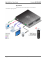
1
Crestron HD-SCALER
High-Definition Video Scaler
Operations & Installation Guide
Regulatory Compliance
As of the date of manufacture, the HD-SCALER has been tested and found to comply with specifications for
CE marking.
Federal Communications Commission (FCC) Compliance Statement
This device complies with part 15 of the FCC Rules. Operation is subject to the following conditions:
(1) This device may not cause harmful interference and (2) this device must accept any interference received,
including interference that may cause undesired operation.
CAUTION: Changes or modifications not expressly approved by the manufacturer responsible for
compliance could void the user’s authority to operate the equipment.
NOTE: This equipment has been tested and found to comply with the limits for a Class B digital device,
pursuant to part 15 of the FCC Rules. These limits are designed to provide reasonable protection against
harmful interference in a residential installation. This equipment generates, uses and can radiate radio
frequency energy and, if not installed and used in accordance with the instructions, may cause harmful
interference to radio communications. However, there is no guarantee that interference will not occur in a
particular installation. If this equipment does cause harmful interference to radio or television reception,
which can be determined by turning the equipment off and on, the user is encouraged to try to correct the
interference by one or more of the following measures:
•
Reorient or relocate the receiving antenna
•
Increase the separation between the equipment and receiver
•
Connect the equipment into an outlet on a circuit different from that to which the receiver is connected
•
Consult the dealer or an experienced radio/TV technician for help
Industry Canada (IC) Compliance Statement
CAN ICES-3(B)/NMB-3(B)
The specific patents that cover Crestron products are listed at patents.crestron.com.
Crestron, the Crestron logo, Cresnet, Creston Studio, Crestron Toolbox, QuickMedia, and QuickSwitch HD are either trademarks or registered
trademarks of Crestron Electronics, Inc. in the United States and/or other countries. Dolby Digital is either a trademark or registered trademark of
Dolby Laboratories in the United States and/or other countries. DTS is either a trademark or registered trademark of DTS, Inc. in the United States
and/or other countries. HDMI and the HDMI Logo are either trademarks or registered trademarks of HDMI Licensing LLC in the United States and/or
other countries. Other trademarks, registered trademarks, and trade names may be used in this document to refer to either the entities claiming the
marks and names or their products. Crestron disclaims any proprietary interest in the marks and names of others. Crestron is not responsible for errors
in typography or photography.
This document was written by the Technical Publications department at Crestron.
©2014 Crestron Electronics, Inc.
Crestron HD-SCALER
High-Definition Video Scaler
Contents
High-Definition Video Scaler: HD-SCALER
1
Introduction ............................................................................................................................... 1
Features and Functions ................................................................................................ 1
Applications................................................................................................................. 4
Specifications .............................................................................................................. 5
Physical Description .................................................................................................. 10
Setup ........................................................................................................................................ 14
Network Wiring ......................................................................................................... 14
Identity Code ............................................................................................................. 14
Installation ................................................................................................................. 15
Hardware Hookup ..................................................................................................... 17
Uploading and Upgrading ........................................................................................................ 18
Establishing Communication ..................................................................................... 18
Firmware ................................................................................................................... 18
IR Remote Operation ............................................................................................................... 20
On-Screen Display ................................................................................................................... 22
Configuration ........................................................................................................................... 25
Configuring Analog Input Parameters ....................................................................... 25
Configuring Digital Input Parameters ....................................................................... 26
Configuring Output Parameters ................................................................................. 27
Problem Solving ...................................................................................................................... 28
Troubleshooting......................................................................................................... 28
Check Network Wiring.............................................................................................. 28
Further Inquiries ........................................................................................................ 29
Future Updates .......................................................................................................... 29
Return and Warranty Policies .................................................................................................. 30
Merchandise Returns / Repair Service ...................................................................... 30
Crestron Limited Warranty........................................................................................ 30
Operations & Installation Guide – DOC. 7136B
Contents • i
Crestron HD-SCALER
High-Definition Video Scaler
High-Definition Video Scaler:
HD-SCALER
Introduction
The HD-SCALER provides a simple and cost-effective universal scaler solution with
advanced features for adapting any digital HD display, projector, or codec to handle
virtually any video signal regardless of resolution or format. The compact,
low-profile design of the HD-SCALER allows it to be installed discreetly behind a
flat-panel display, above a ceiling projector, or in the back of an equipment rack.
Features and Functions
•
•
•
•
•
•
•
•
•
•
•
•
•
•
•
Compact, low-profile surface mount design
Automatically scales any input signal to match the native resolution of
the display
Perfect for adapting all kinds of video devices to handle any resolution
and format
Supports input/output resolutions up to HD 1080p and UXGA/
WUXGA1
Performs deinterlacing of NTSC, PAL, and 1080i sources
Handles HDMI® signals with HDCP
Also handles DVI and DisplayPort Multimode sources2
Supports analog RGBHV, RGBS, RGsB, component, composite, and
S-video sources3
Allows advanced management of EDID
Allows adjustable overscan and underscan up to 7.5%
Features auto-switching between digital and analog sources
Handles 7.1 digital audio and analog stereo audio signals
Allows embedding of analog audio to HDMI
Setup via on-screen display using IR wireless remote (included)
Provides detailed input/output signal information on screen
(Continued on following page)
1. The HD-SCALER supports any input or output resolution and scan rate that has a pixel clock of
165 MHz or lower.
2. HDMI IN requires an appropriate adapter or interface cable to accommodate a DVI or DisplayPort
multimode signal. HDMI OUT requires an appropriate adapter or interface cable to accommodate a
DVI signal. CBL-HD-DVI interface cables sold separately.
3. The RGBHV input can accept component, composite, and S-video signals via direct interface to
Crestron® MPS Series products, or through an appropriate adapter (not included). Composite and
S-video signals are not detected automatically and must be selected programmatically or manually.
Operations & Installation Guide – DOC. 7136B
High-Definition Video Scaler: HD-SCALER • 1
Crestron HD-SCALER
High-Definition Video Scaler
Features and Functions
(Continued)
•
•
•
•
Includes built-in test patterns for precise display setup
Allows control system integration via Cresnet®
Affords a seamless upgrade for Crestron MPS and QuickMedia®
systems
Provides a powerful portable diagnostic tool for any video setup
Universal HD Scaler
The HD-SCALER connects to the HDMI or DVI input of a video display. Fully
automatic operation is achieved using the display’s EDID1—just insert the
HD-SCALER into the incoming video signal path and it intelligently converts and
enhances that signal for optimal appearance on the display.
Both HDMI and RGBHV inputs are provided, accommodating modern digital
sources such as HDMI, DVI, and DisplayPort Multimode 2 as well as analog
VGA/RGB, component, S-video,3 and composite video.3 Input source selection can
occur automatically via built-in auto-detection or programmatically via integration
with a Crestron control system.
The HD-SCALER handles standard and high-definition video sources with
resolutions up to 1080p60 progressive and 1080i30 interlaced, as well as computer
sources up to UXGA 1600x1200 and WUXGA 1920x1200. Whatever the source, the
HD-SCALER is capable of scaling it up or down, deinterlacing it, reducing noise
artifacts, and adjusting its aspect ratio to match the native resolution of the video
display or computer monitor. Any display resolution up to 1920x12004 can be
supported, with auto-calibration ensuring a quick and easy setup and hands-off
operation.
On-Screen Display
Advanced setup and diagnostics is facilitated through an intuitive on-screen display
(OSD). The OSD appears on the video display with navigation enabled using an IR
remote (included). The OSD displays detailed information about each connected
source and display device. This information includes the video resolution, refresh
rate, pixel clock, color space, and color depth, as well as the audio format and
sampling frequency. The OSD and remote enable manual control over input
selection, output resolution, image brightness and contrast, horizontal/vertical
position, phase, RGB color balance, overscan, and underscan. Management of
EDID1 is also accessible through the OSD.
1. EDID (Extended Display Identification Data) is data embedded in an HDMI, DVI, or VGA signal that
enables a display device to tell the source device what resolutions and formats it can support, allowing
the source to configure itself automatically to feed the best signal that both devices can support.
2. HDMI IN requires an appropriate adapter or interface cable to accommodate a DVI or DisplayPort
multimode signal. HDMI OUT requires an appropriate adapter or interface cable to accommodate a
DVI signal. CBL-HD-DVI interface cables sold separately.
3. The RGBHV input can accept component, composite, and S-video signals via direct interface to
Crestron MPS Series products or through an appropriate adapter (not included). Composite and
S-video signals are not detected automatically and must be selected programmatically or manually.
4. The HD-SCALER supports any input or output resolution and scan rate that has a pixel clock of
165 MHz or lower.
2 • High-Definition Video Scaler: HD-SCALER
Operations & Installation Guide – DOC. 7136B
Crestron HD-SCALER
High-Definition Video Scaler
Built-In Test Patterns
To ensure optimum performance and proper setup without necessitating any
additional test equipment, the HD-SCALER includes a complete assortment of
professional video test patterns. These include various color bars, line and grid
patterns, RGB and grayscale ramps, streak and streak boost, raster, solid colors, and
several aspect ratio boxes. Even as a portable device, the HD-SCALER provides an
invaluable setup tool.
Audio Capabilities
Normally, the audio source follows the active video input, passing up to 8-channel
digital audio via HDMI and 2-channel analog audio alongside RGBHV. However,
the audio breakaway capability of the HD-SCALER also allows combining analog
audio with digital video from an HDMI or DVI source, embedding the analog audio
and digital video signals into one HDMI output.
Unparalleled System Integration
The HD-SCALER is well-suited for a wide range of applications including
boardrooms and classrooms, home entertainment, rental and staging, and digital
signage. Its simple set-and-forget nature and compact size let it go anywhere a
high-quality video scaler is needed. In addition, built-in Cresnet connectivity
allows for remote control over input selection and numerous other functions.
The HD-SCALER can be powered through the Cresnet connection or via a local
power pack (included).
Digital Upgrade for Legacy Systems
The HD-SCALER is ideal for adding digital connectivity and scaling to existing AV
systems. Through a single VGA cable, its RGBHV input can be connected directly to
the output of a Crestron MPS system or QuickMedia receiver, converting every
analog RGB, component, S-video,* and composite* video signal to HDMI and
scaling the output to feed a high-definition digital display or projector. Analog audio
is converted similarly through a simple stereo audio cable. Digital AV sources are
easily accommodated via the HDMI input, which can be expanded simply using a
Crestron QuickSwitch HD® HDMI Switcher (HD-MD8X1 or HD-MD8X2, sold
separately).
*
The RGBHV input can accept component, composite, and S-video signals via direct interface to
Crestron MPS Series products or through an appropriate adapter (not included). Composite and
S-video signals are not detected automatically and must be selected programmatically or manually.
Operations & Installation Guide – DOC. 7136B
High-Definition Video Scaler: HD-SCALER • 3
High-Definition Video Scaler
Crestron HD-SCALER
Applications
The diagram below shows an HD-SCALER in a typical application.
HD-SCALER in a Typical Application
4 • High-Definition Video Scaler: HD-SCALER
Operations & Installation Guide – DOC. 7136B
Crestron HD-SCALER
High-Definition Video Scaler
Specifications
Specifications for the HD-SCALER are listed in the following table.
HD-SCALER Specifications
SPECIFICATION
Features
DETAILS
Universal HD video scaler and
deinterlacer, 3D motion-adaptive filter, 3D
noise reduction, MPEG noise reduction,
2:2 and 2:3 pull-down sequence
detection, diagonal line interpolation,
EDID management, input auto-detection
1
and auto-switching, built-in test patterns,
OSD setup with IR remote, Cresnet
network controllable, audio breakaway,
HDMI audio embedding
Video
Switcher
2 x 1 combination digital/analog switch,
Crestron QuickSwitch HD
Input Signal Types
HDMI, DVI, DisplayPort Multimode,
1
RGB, component (YPbPr), S-video
1
1
(Y/C), composite
Output Signal Types
HDMI, DVI
Formats
HDMI, DVI, HDCP content protection
support, RGBHV/RGBS/ RGsB up to
UXGA/WUXGA, HD video up to
1080p60, NTSC or PAL
2
2
2
Input Resolutions
HDMI and DVI,
Progressive
640 x 480 @ 60 Hz
720 x 480 @ 60 Hz (480p)
720 x 576 @ 50 Hz (576p)
800 x 600 @ 60 Hz
848 x 480 @ 60 Hz
852 x 480 @ 60 Hz
854 x 480 @ 60 Hz
1024 x 768 @ 60 Hz
1024 x 852 @ 60 Hz
1024 x 1024 @ 60 Hz
1280 x 720 @ 50 Hz (720p50)
1280 x 720 @ 60 Hz (720p60)
1280 x 768 @ 60 Hz
1280 x 800 @ 60 Hz
1280 x 960 @ 60 Hz
1280 x 1024 @ 60 Hz
1360 x 768 @ 60 Hz
1365 x 1024 @ 60 Hz
1366 x 768 @ 60 Hz
1400 x 1050 @ 60 Hz
1440 x 900 @ 60 Hz
1600 x 900 @ 60 Hz
1600 x 1200 @ 60 Hz
1680 x 1050 @ 60 Hz
1920 x 1080 @ 24 Hz (1080p24)
1920 x 1080 @ 50 Hz (1080p50)
1920 x 1080 @ 60 Hz (1080p60)
(Continued on following page)
Operations & Installation Guide – DOC. 7136B
High-Definition Video Scaler: HD-SCALER • 5
Crestron HD-SCALER
High-Definition Video Scaler
HD-SCALER Specifications (Continued)
SPECIFICATION
DETAILS
Input Resolutions
HDMI and DVI,
Progressive
(Continued)
1920 x 1200 @ 60 Hz
2048 x 1080 @ 24 Hz
2048 x 1152 @ 60 Hz
plus any other resolution up to 165 MHz
pixel clock
HDMI and DVI,
Interlaced
720 x 480 @ 30 Hz (480i)
720 x 576 @ 25 Hz (576i)
1920 x 1080 @ 25 Hz (1080i25)
1920 x 1080 @ 30 Hz (1080i30)
plus any other resolution up to 165 MHz
pixel clock
RGB
640 x 480 @ 60 Hz
720 x 480 @ 60 Hz (480p)
720 x 576 @ 50 Hz (576p)
800 x 600 @ 60 Hz
848 x 480 @60Hz
1024 x 768 @ 60 Hz
1280 x 720 @ 50 Hz (720p50)
1280 x 720 @ 60 Hz (720p60)
1280 x 768 @ 60Hz
1280 x 800 @ 60 Hz
1280 x 960 @ 60 Hz
1280 x 1024 @ 60 Hz
1360 x 768 @ 60 Hz
1366 x 768 @ 60 Hz
1400 x 1050 @ 60 Hz
1440 x 900 @ 60 Hz
1600 x 1200 @ 60 Hz
1680 x 1050 @ 60 Hz
1920 x 1080 @ 50 Hz (1080p50)
1920 x 1080 @ 60Hz (1080p60)
1920 x 1200 @ 60Hz
Component
1
480i
576i
480p
576p
720p50
720p60
1080p24
1080i25 (1125 lines)
1080i30
1080p30
1080p50 (1125 lines)
1080p60
1
Composite and S-video
480i
576i
(Continued on following page)
6 • High-Definition Video Scaler: HD-SCALER
Operations & Installation Guide – DOC. 7136B
Crestron HD-SCALER
High-Definition Video Scaler
HD-SCALER Specifications (Continued)
SPECIFICATION
DETAILS
Scaler Output Resolutions
Progressive
640 x 480 @ 60 Hz
720 x 480 @ 60 Hz (480p)
720 x 576 @ 50 Hz (576p)
800 x 600 @ 60Hz
848 x 480 @ 60Hz
1024 x 768 @ 60 Hz
1280 x 720 @ 50 Hz (720p50)
1280 x 720 @ 60 Hz (720p60)
3
1280 x 768 @ 60 Hz
3
1280 x 800 @ 60 Hz
1280 x 960 @ 60 Hz
1280 x 1024 @ 60 Hz
1360 x 768 @ 60 Hz
3
1366 x 768 @ 60 Hz
3
1400 x 1050 @ 60 Hz
3
1440 x 900 @ 60 Hz
4
1600 x 900 @ 60 Hz
1600 x 1200 @ 60 Hz
4
1680 x 1050 @ 60 Hz
1920 x 1080 @ 50 Hz (1080p50)
1920 x 1080 @ 60 Hz (1080p60)
4
1920 x 1200 @ 60 Hz
4
2048 x 1152 @ 60 Hz
plus any other resolution up to 165 MHz
pixel clock
Interlaced
1920 x 1080 @ 25 Hz (1080i25)
1920 x 1080 @ 30 Hz (1080i30)
Analog-to-Digital Conversion
10-bit 165 MHz per each of 3 channels
Audio
Switcher
2 x 1 combination digital/analog switch
Input Signal Types
HDMI, DisplayPort Multimode,
analog stereo
Output Signal Type
HDMI
2
Formats
®
®
HDMI
Dolby Digital , Dolby Digital EX, DTS ,
DTS-ES, DTS 96/24, up to 8 channel
PCM
Analog
Stereo 2-Channel
Analog-to-Digital Conversion
24-bit 48 kHz
(Continued on following page)
Operations & Installation Guide – DOC. 7136B
High-Definition Video Scaler: HD-SCALER • 7
Crestron HD-SCALER
High-Definition Video Scaler
HD-SCALER Specifications (Continued)
SPECIFICATION
DETAILS
Audio (Continued)
Performance (Analog)
Frequency Response
20 Hz to 20 kHz ±0.75 dB
S/N Ratio
>90 dB, 20 Hz to 20 kHz A-weighted
THD+N
<0.05% @ 1 kHz (line)
Stereo Separation
>90 dB
Communications
Cresnet
Supports Cresnet slave mode for control
HDMI
Passes CEC, manages EDID, supports
HDCP
USB
For console, USB 2.0 client
Remote
5
19 button IR wireless remote for OSD
navigation
Power Requirements
Power Pack
0.75 amp @ 24 Vdc;
100-240 Vac, 50/60 Hz power pack
included
Cresnet Power Usage
10 watts (0.42 amp @ 24 Vdc) with no
power pack connected
Battery
(1) CR2032 disposable lithium battery for
remote (included)
Environmental
Temperature
32º to 104ºF (0º to 40ºC)
Humidity
10% to 90% RH (non-condensing)
Heat Dissipation
30 Btu/h
Enclosure
Chassis
Metal, matte black finish with two integral
mounting flanges; vented front, top, and
bottom
Mounting
Freestanding, surface mount, or attach to
a single rack rail
Dimensions
Height
7.36 in (187 mm)
Width
7.43 in (189 mm)
Depth
1.24 in (32 mm)
Weight
1.8 lb (0.79 kg)
Included Accessory
24 Vdc Power Pack, Universal
(Continued on following page)
8 • High-Definition Video Scaler: HD-SCALER
Operations & Installation Guide – DOC. 7136B
Crestron HD-SCALER
High-Definition Video Scaler
HD-SCALER Specifications (Continued)
SPECIFICATION
DETAILS
Available Accessories
CBL-AUDIO
Crestron Certified Mini-TRS Stereo Audio
Interface Cable
CBL-HD
Crestron Certified HDMI Interface Cable
CBL-HD-DVI
Crestron Certified HDMI to DVI Interface
Cable
CBL-HD-LOCK
Locking High-Speed HDMI Cable
CBL-VGA
Crestron Certified Computer VGA
Interface Cable
CBL-VGA-AUD
Crestron Certified Computer VGA
Interface Cable with Mini-TRS Audio
CRESNET
Cresnet Control Cable
1. The RGBHV input can accept component, composite, and S-video signals via direct interface to
Crestron MPS Series products or through an appropriate adapter (not included). However, composite
and S-video signals are not detected automatically and must be selected programmatically or
manually.
2. HDMI IN requires an appropriate adapter or interface cable to accommodate a DVI or DisplayPort
multimode signal. HDMI OUT requires an appropriate adapter or interface cable to accommodate a
DVI signal. CBL-HD-DVI interface cables sold separately.
3. With or without reduced blanking.
4. With reduced blanking only.
5. EDID (Extended Display Identification Data) is data embedded in an HDMI, DVI, or VGA signal that
enables a display device to tell the source device what resolutions and formats it can support, allowing
the source to configure itself automatically to feed the best signal that both devices can support.
Operations & Installation Guide – DOC. 7136B
High-Definition Video Scaler: HD-SCALER • 9
High-Definition Video Scaler
Crestron HD-SCALER
Physical Description
This section provides information on the connections, controls, and indicators
available on the HD-SCALER.
HD-SCALER Physical Views (Left and Right Sides Shown)
10 • High-Definition Video Scaler: HD-SCALER
Operations & Installation Guide – DOC. 7136B
Crestron HD-SCALER
High-Definition Video Scaler
HD-SCALER Overall Dimensions (Front and Right Side Views)
6.89 in
(175 mm)
7.36 in
(187 mm)
5.25 in
(134 mm)
1.24 in
(32 mm)
7.43 in
(189 mm)
HD-SCALER Connectors, Controls, and Indicators (Left and Right Side Views)
1
2
9
10
3
4
11
5
6
7
12
14
13
15
8
Operations & Installation Guide – DOC. 7136B
High-Definition Video Scaler: HD-SCALER • 11
Crestron HD-SCALER
High-Definition Video Scaler
Connectors, Controls, and Indicators
1
#
CONNECTORS,
CONTROLS, AND
INDICATORS
DESCRIPTION
1
AUDIO IN
(1) 3.5 mm TRS mini phone jack;
Unbalanced stereo line-level audio input;
Input Impedance: 10 kilohms;
Input Level: 2 Vrms maximum
2
RGBHV IN
(1) DB15HD female, RGB (VGA),
component, S-video, or composite video
2
input;
Formats: RGBHV, RGBS, RGsB, YPbPr,
Y/C, NTSC, PAL;
Input Levels: 0.5 to 1.5 Vp-p with built-in
dc restoration;
Input Impedance: 75 ohms;
Sync Input Type: Autodetect RGBHV,
RGBS, RGsB, YPbPr;
Sync Input Level: 3 to 5 Vp-p;
Sync Input Impedance: 1 kilohm
3
HDMI IN
4
HDMI OUT
5
SETUP
(LED and Button)
(1) Red LED used for touch-settable ID
(TSID) and (1) recessed push button
6
NET
(1) 3.5 mm detachable terminal block;
Cresnet slave port, connects to Cresnet
control network;
24: Power (24 Vdc)
Y: Data
Z: Data
G: Ground
7
PWR
24 VDC 0.75 A
(1) 19-pin Type A HDMI female;
HDMI digital video/audio input;
Also supports DVI and DisplayPort
3
Multimode
8
(1) 19-pin Type A HDMI female;
HDMI digital video/audio output;
3
Also supports DVI
(1) 2.1 x 5.5 mm barrel dc power
connector;
24 Vdc power input; power pack included
(1) 6-32 screw, chassis ground lug
9
RESET
10
(1) Recessed push button for
hardware reset
COMPUTER
Pin 2
Pin 1
(1) USB Type B female;
USB 2.0 computer console port
(6 foot [~1.8 meters] cable included)
PIN
Pin 3
Pin 4
DESCRIPTION
1
+5 Vdc
2
Data -
3
Data +
4
Ground
(Continued on following page)
12 • High-Definition Video Scaler: HD-SCALER
Operations & Installation Guide – DOC. 7136B
Crestron HD-SCALER
High-Definition Video Scaler
Connectors, Controls, and Indicators (Continued)
1
#
CONNECTOR6
CONTROLS, AND
INDICATORS
11
IR IN
12
HDMI OUT LED
(1) Green LED, indicates output signal
presence
13
HDMI IN LED
(1) Green LED, indicates HDMI input is
selected
14
RGB IN LED
(1) Green LED, indicates RGB input is
selected
15
PWR LED
(1) Green LED, indicates 24 Vdc power
supplied via Cresnet network or local
power pack
DESCRIPTION
(1) IR receiver window for use with
remote provided
1. Interface connector for the NET port is provided with the unit.
2. The RGBHV input can accept component, composite, and S-video signals via direct interface to
Crestron MPS Series products or through an appropriate adapter (not included). Composite and
S-video signals are not detected automatically and must be selected programmatically or manually.
Refer to the following table for the RGBHV IN connector pinouts.
RGBHV IN Connector Pinouts
PIN 5
PIN 10
PIN 15
PIN 1
PIN 6
PIN 11
PIN #
RGB
YPbPr
S-VIDEO
1
R
Pr
C
2
G
Y
Y
3
B
Pb
5
Gnd
Gnd
Gnd
6
Red_Gnd
Pr_Gnd
C_Gnd
7
Grn_Gnd
Y_Gnd
Y_Gnd
8
Blu_Gnd
Pb_Gnd
13
H
14
V
COMPOSITE
Comp
Gnd
For best video performance, grounds should be kept separate. Grounds should not be connected to the
connector shell. The connector shell is reserved for the cable shield.
3. HDMI IN requires an appropriate adapter or interface cable to accommodate a DVI or DisplayPort
multimode signal. HDMI OUT requires an appropriate adapter or interface cable to accommodate a
DVI signal. CBL-HD-DVI interface cables sold separately.
Operations & Installation Guide – DOC. 7136B
High-Definition Video Scaler: HD-SCALER • 13
Crestron HD-SCALER
High-Definition Video Scaler
Setup
Network Wiring
When wiring the Cresnet network, consider the following:
•
Use Crestron Certified Wire.
•
Use Crestron power supplies for Crestron equipment.
CAUTION: Failure to use Crestron power supplies could cause equipment
damage or void the Crestron warranty.
•
Provide sufficient power to the system.
CAUTION: Insufficient power can lead to unpredictable results or damage
to the equipment. Use the Crestron Power Calculator to help calculate how
much power is needed for the system (www.crestron.com/calculators).
For Cresnet networks with 20 or more devices, use a Cresnet Hub/Repeater
(CNXHUB) to maintain signal quality.
For more details, refer to “Check Network Wiring” on page 28.
Identity Code
NOTE: The latest software can be downloaded at www.crestron.com/software.
The Net ID of the HD-SCALER has been factory set to A3. The Net IDs of multiple
HD-SCALER devices in the same system must be unique. Net IDs are changed from
a personal computer (PC) via Crestron Toolbox™ (refer to “Establishing
Communication” on page 18).
When setting the Net ID, consider the following:
•
The Net ID of each unit must match an ID code specified in the Crestron
Studio™ or SIMPL Windows program.
•
Each network device must have a unique Net ID.
For more details, refer to the Crestron Toolbox help file.
14 • High-Definition Video Scaler: HD-SCALER
Operations & Installation Guide – DOC. 7136B
Crestron HD-SCALER
High-Definition Video Scaler
Installation
Ventilation
The HD-SCALER should be used in a well-ventilated area. The venting holes should
not be obstructed under any circumstances.
To prevent overheating, do not operate this product in an area that exceeds the
environmental temperature range listed in the table of specifications.
Mounting the HD-SCALER
The HD-SCALER mounts on a flat surface such as a wall or ceiling. The
HD-SCALER can also be mounted on a rack rail.
Mounting on a Flat Surface
To mount the HD-SCALER on a flat surface such as a wall or ceiling, use four
mounting screws (not included). The following illustration shows mounting of the
HD-SCALER on a wall.
Mounting the HD-SCALER on a Wall
Mounting Screws (4)
(Not Included)
Operations & Installation Guide – DOC. 7136B
High-Definition Video Scaler: HD-SCALER • 15
Crestron HD-SCALER
High-Definition Video Scaler
Rack Mounting
To mount the HD-SCALER on the front or rear rail of a rack, do the following:
1.
Position either mounting flange of the HD-SCALER so that the holes align
with the holes in the rack (refer to the illustration below).
2.
Secure the device to the rack using two rack mounting screws (not
included).
Mounting the HD-SCALER on a Rack Rail
Rack Mounting
Screws
(Not Included)
16 • High-Definition Video Scaler: HD-SCALER
Operations & Installation Guide – DOC. 7136B
Crestron HD-SCALER
High-Definition Video Scaler
Hardware Hookup
Make the necessary connections as called out in the following illustrations. Refer to
“Network Wiring” on page 14. Apply power after all connections have been made.
Hardware Connections for the HD-SCALER (Left Side View)
Ground
AUDIO IN:
From Unbalanced
Stereo Line Level
Audio Source
HDMI IN:
From HDMI
Source
RGBHV IN:
From RGB (VGA) or
Component (YPbPr)
Video Source
NET:
From Cresnet
Power Supply/To
Cresnet Device
PWR:
From Power Pack
(Included)
HDMI OUT:
To HDMI Display/
Receiver
Hardware Connections for the HD-SCALER (Right Side View)
COMPUTER:
To USB Port on PC
(For Firmware
Loading Only)
NOTE: Ensure that the unit is properly grounded by connecting the chassis ground
lug to an earth ground (building steel).
NOTE: The supported power supply configuration is either the external power pack
(included) or a Cresnet power supply. A Cresnet power supply and the included
power pack cannot be connected to the HD-SCALER at the same time.
Operations & Installation Guide – DOC. 7136B
High-Definition Video Scaler: HD-SCALER • 17
Crestron HD-SCALER
High-Definition Video Scaler
Uploading and Upgrading
Crestron recommends using the latest programming software and that each device
contains the latest firmware to take advantage of the most recently released features.
However, before attempting to upload or upgrade it is necessary to establish
communication. Once communication has been established, files (for example,
firmware) can be transferred to the device.
NOTE: Crestron software and any files on the website are for authorized Crestron
dealers and Crestron Service Providers (CSPs) only. New users must register to
obtain access to certain areas of the site (including the FTP site).
Establishing Communication
Use Crestron Toolbox for communicating with the HD-SCALER; refer to the
Crestron Toolbox help file for details. There is one method of communication: USB.
USB Communication
HD-SCALER
R
R
DIO
IN
V
ID
E
AU
O
S
C
A
L
LE
-SCA
HD
E
USB
RG
BH
V IN
IN
HD
MI
OU
T
SE
TU
P
HD
YZMI
G
24
NE
T
PW
R
PC Running
Crestron Toolbox
The COMPUTER port on the HD-SCALER connects to the USB port on the PC via
a Type A to Type B USB cable:
1.
Use the Address Book in Crestron Toolbox to create an entry using the
expected communication protocol (USB). When multiple USB devices are
connected, identify the HD-SCALER by entering “HD-SCALER” in the
Model text box, the unit’s serial number in the Serial text box or the unit’s
hostname in the Hostname text box. The hostname can be found in the
“System Info” window in the Ethernet section of the window; however,
communications must be established in order to see this information in the
“System Info” window.
2.
Display the HD-SCALER’s “System Info” window (Tools | System Info);
communications are confirmed when the device information is displayed.
Firmware
Firmware files may be distributed from programmers to installers or from Crestron
to dealers. Firmware upgrades are available from the Crestron website as new
features are developed after product releases. For details on upgrading, refer to the
Crestron Toolbox help file.
Check the Crestron website to find the latest firmware. (New users must register to
obtain access to certain areas of the site, including the FTP site.)
Upgrade HD-SCALER firmware using Crestron Toolbox:
1.
Download the appropriate .puf file from the Crestron website to the PC.
2.
Double-click the .puf file. The Toolbox Address Book opens.
18 • High-Definition Video Scaler: HD-SCALER
Operations & Installation Guide – DOC. 7136B
Crestron HD-SCALER
High-Definition Video Scaler
3.
From the list in the Address Book, select the entry listed for the
HD-SCALER (the address is listed as USB), and then click OK.
The HD device list is displayed, and the checkbox of the HD-SCALER
firmware is automatically selected.
4.
Click Update.
5.
After the process is complete, click Recheck to verify the upgrade.
Operations & Installation Guide – DOC. 7136B
High-Definition Video Scaler: HD-SCALER • 19
Crestron HD-SCALER
High-Definition Video Scaler
IR Remote Operation
The HD-SCALER is shipped from the factory with an IR remote (refer to the
illustration below).
HD-SCALER IR Remote
To operate the remote, point it at the IR IN receiver window on the HD-SCALER
and press the appropriate buttons. Refer to the table below for descriptions of the
buttons.
IR Remote Buttons
BUTTON
DESCRIPTION
MENU
Accesses or closes the HD-SCALER On-Screen
Display (OSD) (refer to “On-Screen Display” on
page 22 for additional information).
INFO
Shows or hides information about input and output
formats.
OK
Selects OSD menu items or settings.
and
Up and Down navigation buttons.
and
Left and right navigation buttons.
Left button also functions as a back button to
return to the previous level in the OSD.
(Continued on following page)
20 • High-Definition Video Scaler: HD-SCALER
Operations & Installation Guide – DOC. 7136B
Crestron HD-SCALER
High-Definition Video Scaler
IR Remote Buttons (Continued)
BUTTON
DESCRIPTION
EDID
DFLT/COPY
Specifies whether the analog/digital input EDID is
to be set to DFLT in which the HD-SCALER
sends a list of default resolutions to the source or
set to COPY in which resolutions are read from
the display and sent to the source.
NOTE: If RGB video has been selected by
pressing the RGB video button on the remote,
then the analog input EDID is set. If digital video
has been selected by pressing the HDMI video
button on the remote, then the digital input EDID
is set.
ASPECT
1:1/NORM/ZOOM/STRCH
AUDIO
AUTO/ALOG/HDMI
VIDEO
AUTO/RGB/HDMI
Operations & Installation Guide – DOC. 7136B
Specifies one of the following:
•
1:1: Matches the resolution of the image on
the display with the input resolution of the
source image. For example, if the output
resolution is 1080p and the input resolution is
640x480, the resolution of the image on the
display is 640x480 with a black bar
surrounding it. If the image size is larger than
the total resolution of the display, the image is
cropped to the size of the display.
•
NORM: Fits the source image within the
display while maintaining the aspect ratio of
the image on the display. If the source image
is smaller than the total resolution of the
display, the image is enlarged to fit the
display. If the source image is larger than the
total resolution of the display, the image is
reduced to fit the display.
•
ZOOM: Zooms in on the image while
maintaining the aspect ratio. Cropping of the
image may occur.
•
STRCH: Depending on the input and output
resolutions, stretches the image horizontally,
vertically, or both horizontally and vertically to
fill the display. The aspect ratio of the image
is not maintained.
Specifies one of the following:
•
AUTO: Automatically detects the audio input
source: analog, HDMI (digital), or both. If both
analog and HDMI audio inputs are detected,
HDMI is selected as the preferred audio
setting.
•
ALOG: Sets the audio to analog.
•
HDMI: Sets the audio to HDMI (digital).
Specifies one of the following:
•
AUTO: Automatically detects the video input
source: RGB (analog), HDMI (digital), or both.
If both RGB and HDMI video inputs are
detected, HDMI is selected as the preferred
video setting.
•
RGB: Sets the video to RGB (analog).
•
HDMI: Set the video to HDMI (digital).
High-Definition Video Scaler: HD-SCALER • 21
Crestron HD-SCALER
High-Definition Video Scaler
On-Screen Display
The HD-SCALER on-screen display (OSD), which appears on the display device,
allows configuration of input and output signal parameters and also provides access
to information about the HD-SCALER. The main menu of the HD-SCALER OSD is
shown below.
HD-SCALER OSD Main Menu
As shown above, the main menu of the HD-SCALER OSD consists of five items:
1.
Analog Input: Accesses the Analog Input submenu, which allows
configuration of analog input parameters (refer to “Configuring Analog
Input Parameters” on page 25 for additional information). Also allows
display of analog input signal information.
2.
Digital Input: Accesses the Digital Input submenu, which allows
configuration of digital input parameters (refer to “Configuring Digital
Input Parameters” on page 26 for additional information). Also allows
display of digital input signal information.
3.
Output: Accesses the Output submenu, which allows configuration of
video and audio output parameters (refer to “Configuring Output
Parameters” on page 27 for additional information). Also allows display of
EDID video and audio information.
4.
Device Information: Provides HD-SCALER firmware and hardware
versions and debug information.
5.
Restore Defaults: Reboots the HD-SCALER and restores configuration
settings to the default values.
The illustration on the following page provides a menu tree of the HD-SCALER
OSD.
22 • High-Definition Video Scaler: HD-SCALER
Operations & Installation Guide – DOC. 7136B
Crestron HD-SCALER
High-Definition Video Scaler
HD-SCALER OSD Menu Tree
HD-SCALER
On-Screen Display Menu
Digital
Input
Analog
Input
Device
Information
Output
Auto
Calibrate
Contrast
Resolution
Contrast
Brightness
Underscan
Brightness
EDID
Test
Patterns
Horizontal
Position
Overscan
EDID
Video Info
Vertical
Position
Signal
Information
EDID
Audio Info
Phase Coarse
Restore
Defaults
Signal
Information
Phase Fine
Color Red
Color Green
Color Blue
EDID
Overscan
Source
Control
Signal
Information
Operations & Installation Guide – DOC. 7136B
High-Definition Video Scaler: HD-SCALER • 23
Crestron HD-SCALER
High-Definition Video Scaler
The following provides an overview of OSD operation using the IR remote:
•
To access the OSD, press MENU. Pressing MENU a second time closes
the OSD.
•
To navigate up or down in a menu or in a list of available configuration
or .
settings, use
•
To select a highlighted item in a menu or in a list of available configuration
settings, press OK.
•
To go back to the previous level (for example, to a submenu or to the main
menu), use .
•
To navigate to the left (-) or to the right (+) when adjusting a setting in a
slider (for example, Brightness), use or .
•
To save a setting in a slider, press OK.
24 • High-Definition Video Scaler: HD-SCALER
Operations & Installation Guide – DOC. 7136B
Crestron HD-SCALER
High-Definition Video Scaler
Configuration
Configuration of input and output signals is performed from the HD-SCALER OSD
using the supplied IR remote. For information about the remote, refer to “IR Remote
Operation” on page 20.
Configuring Analog Input Parameters
To configure analog input parameters, navigate to the Analog Input main menu item
and then press OK on the IR remote.
The Analog Input submenu appears as shown below.
Analog Input Submenu
The Analog Input submenu allows configuration of the following parameters:
•
Auto Calibrate: Automatically centers the image on the display.
•
Contrast: Adjusts the contrast level of the video signal.
•
Brightness: Adjusts the brightness level of the video signal.
•
Horizontal Position: Adjusts the horizontal positioning of the video signal.
•
Vertical Position: Adjusts the vertical positioning of the video signal.
•
Phase - Coarse: Adjusts the coarse phase level of the video signal.
•
Phase - Fine: Adjusts the fine phase level of the video signal.
•
Color - Red: Adjusts the red color component of the video signal.
•
Color - Green: Adjusts the green color component of the video signal.
•
Color - Blue: Adjusts the blue color component of the video signal.
•
EDID: Specifies whether the analog input EDID is to be set to the default
EDID of the display or copied (cloned) from the output EDID of the
display.
Operations & Installation Guide – DOC. 7136B
High-Definition Video Scaler: HD-SCALER • 25
Crestron HD-SCALER
High-Definition Video Scaler
•
Overscan: Sets overscan to None (default), 2.5%, 5.0%, or 7.5%.
•
Source Control: Sets the video input signal type: Auto, RGB, YPbPr,
S-Video, CVBS, or CVBS (VCR mode). When set to Auto, only RGB and
component video signals are automatically detected.
In addition, the Signal Information menu item provides display of analog input
signal information.
Configuring Digital Input Parameters
To configure digital input parameters, navigate to the Digital Input main menu item
and then press OK on the IR remote.
The Digital Input submenu appears as shown below.
Digital Input Submenu
The Digital Input submenu allows configuration of the following parameters:
•
Contrast: Adjusts the contrast level of the video.
•
Brightness: Adjusts the brightness level of the video.
•
EDID: Specifies whether the digital input EDID is to be set to the default
EDID of the display or copied (cloned) from the output EDID of the
display.
•
Overscan: Sets overscan to None (default), 2.5%, 5.0%, or 7.5%.
In addition, the Signal Information menu item provides display of digital input
signal information.
26 • High-Definition Video Scaler: HD-SCALER
Operations & Installation Guide – DOC. 7136B
Crestron HD-SCALER
High-Definition Video Scaler
Configuring Output Parameters
To configure output parameters, navigate to the Output main menu item and then
press OK on the IR remote.
The Output submenu appears as shown below.
Output Submenu
The Output submenu allows configuration of the following parameters:
•
Resolution: Sets the video output resolution.
NOTE: When Resolution is set to Automatic (default setting), the preferred
resolution of the display is used. (Selecting EDID Video Info in the Output
submenu indicates the preferred resolution of the display.)
NOTE: To select a resolution, navigate to the desired resolution and then
press OK on the IR remote. The display shows the selected resolution and
provides a prompt asking whether the resolution is to be kept. Within 15
seconds, select Ok to keep the resolution or Revert to go back to the
previous resolution and then press OK on the IR remote. If OK is not
pressed within 15 seconds or if a resolution that is not supported by the
display is selected, the output reverts to the previous resolution. Depending
on the display, an error may be indicated prior to reverting to the previous
resolution.
NOTE: If the input resolution is 1080p24 and the output resolution is set to
1080p60, turning on the OSD causes the video to blank. The blanking of the
video is the expected behavior.
•
Underscan: Sets underscan to None (default), 2.5%, 5.0%, or 7.5%.
In addition, the Output submenu also allows display of test patterns and provides
display of EDID video and audio information as well as video and audio output
signal information.
Operations & Installation Guide – DOC. 7136B
High-Definition Video Scaler: HD-SCALER • 27
Crestron HD-SCALER
High-Definition Video Scaler
Problem Solving
Troubleshooting
The following table provides corrective action for possible trouble situations.
If further assistance is required, please contact a Crestron customer service
representative.
HD-SCALER Troubleshooting
TROUBLE
POSSIBLE CAUSE(S)
CORRECTIVE ACTION
PWR LED
does not
illuminate.
Device is not receiving
power.
Verify connection via the
Cresnet network or from the
included power pack.
HDMI IN LED
does not
illuminate.
HDMI input is not
selected.
Verify that HDMI is selected.
HDMI OUT
LED does not
illuminate.
Device is not receiving
video signal.
Ensure that proper video signal
is routed to device.
Device connected to the
HDMI OUT port has not
sent the hotplug signal.
Power on device connected to
the HDMI OUT port and ensure
that it is switched to the
correct input.
RGB IN LED
does not
illuminate.
RGB input is not selected.
Verify that RGB is selected.
Device loses
functionality
due to
electrostatic
discharge.
Device is improperly
grounded.
Check that all ground
connections have been made
properly.
Check Network Wiring
Use the Right Wire
To ensure optimum performance over the full range of the installation topology, use
Crestron Certified Wire only. Failure to do so may incur additional charges if
support is required to identify performance deficiencies because of using improper
wire.
Calculate Power
CAUTION: Use only Crestron power supplies for Crestron equipment. Failure to
do so could cause equipment damage or void the Crestron warranty.
CAUTION: Provide sufficient power to the system. Insufficient power can lead to
unpredictable results or damage to the equipment. Use the Crestron Power
Calculator to help calculate how much power is needed for the system
(www.crestron.com/calculators).
When calculating the length of wire for a particular Cresnet run, the wire gauge and
the Cresnet power usage of each network unit to be connected must be taken into
consideration. Use Crestron Certified Wire only. If Cresnet units are to be daisy
chained on the run, the Cresnet power usage of each network unit to be daisy
chained must be added together to determine the Cresnet power usage of the entire
chain. If the unit is run from a Crestron system power supply network port, the
Cresnet power usage of that unit is the Cresnet power usage of the entire run.
28 • High-Definition Video Scaler: HD-SCALER
Operations & Installation Guide – DOC. 7136B
Crestron HD-SCALER
High-Definition Video Scaler
The wire gauge and the Cresnet power usage of the run should be used in the
following equation to calculate the cable length value on the equation’s left side.
Cable Length Equation
40,000
L<
RxP
Where: L = Length of run (or chain) in feet
R = 6 Ohms (Crestron Certified Wire: 18 AWG (0.75 mm2 ))
or 1.6 Ohms (Cresnet HP: 12 AWG (4 mm 2 ))
P = Cresnet power usage of entire run (or chain)
Make sure the cable length value is less than the value calculated on the right side of
the equation. For example, a Cresnet run using 18 AWG Crestron Certified Wire and
drawing 20 watts should not have a length of run more than 333 feet (101 meters). If
Cresnet HP is used for the same run, its length could extend to 1250 feet (381
meters).
NOTE: All Crestron certified Cresnet wiring must consist of two twisted pairs. One
twisted pair is the 24 and G pair and the other twisted pair is the Y and Z pair.
Strip and Tin Wire
When daisy chaining Cresnet units, strip the ends of the wires carefully to avoid
nicking the conductors. Twist together the ends of the wires that share a pin on the
network connector and tin the twisted connection. Apply solder only to the ends of
the twisted wires. Avoid tinning too far up the wires or the end becomes brittle.
Insert the tinned connection into the Cresnet connector and tighten the retaining
screw. Repeat the procedure for the other three conductors.
Add Hubs
Use of a Cresnet Hub/Repeater (CNXHUB) is advised whenever the number of
Cresnet devices on a network exceeds 20 or when the combined total length of
Cresnet cable exceeds 3000 feet (914 meters).
Further Inquiries
To locate specific information or resolve questions after reviewing this guide,
contact Crestron's True Blue Support at 1-888-CRESTRON [1-888-273-7876] or, for
assistance within a particular geographic region, refer to the listing of Crestron
worldwide offices at www.crestron.com/offices.
To post a question about Crestron products, log onto Crestron’s Online Help at
www.crestron.com/onlinehelp. First-time users must establish a user account to fully
benefit from all available features.
Future Updates
As Crestron improves functions, adds new features, and extends the capabilities of
the HD-SCALER, additional information may be made available as manual updates.
These updates are solely electronic and serve as intermediary supplements prior to
the release of a complete technical documentation revision.
Check the Crestron website periodically for manual update availability and its
relevance. Updates are identified as an “Addendum” in the Download column.
Operations & Installation Guide – DOC. 7136B
High-Definition Video Scaler: HD-SCALER • 29
Crestron HD-SCALER
High-Definition Video Scaler
Return and Warranty Policies
Merchandise Returns / Repair Service
1.
No merchandise may be returned for credit, exchange or service without prior authorization from
Crestron. To obtain warranty service for Crestron products, contact an authorized Crestron dealer.
Only authorized Crestron dealers may contact the factory and request an RMA (Return
Merchandise Authorization) number. Enclose a note specifying the nature of the problem, name
and phone number of contact person, RMA number and return address.
2.
Products may be returned for credit, exchange or service with a Crestron Return Merchandise
Authorization (RMA) number. Authorized returns must be shipped freight prepaid to Crestron,
6 Volvo Drive, Rockleigh, N.J. or its authorized subsidiaries, with RMA number clearly marked
on the outside of all cartons. Shipments arriving freight collect or without an RMA number shall
be subject to refusal. Crestron reserves the right in its sole and absolute discretion to charge a 15%
restocking fee plus shipping costs on any products returned with an RMA.
3.
Return freight charges following repair of items under warranty shall be paid by Crestron,
shipping by standard ground carrier. In the event repairs are found to be non-warranty, return
freight costs shall be paid by the purchaser.
Crestron Limited Warranty
Crestron Electronics, Inc. warrants its products to be free from manufacturing defects in materials and
workmanship under normal use for a period of three (3) years from the date of purchase from Crestron,
with the following exceptions: disk drives and any other moving or rotating mechanical parts, pan/tilt heads
and power supplies are covered for a period of one (1) year; touch screen display and overlay components
are covered for 90 days; batteries and incandescent lamps are not covered.
This warranty extends to products purchased directly from Crestron or an authorized Crestron dealer.
Purchasers should inquire of the dealer regarding the nature and extent of the dealer's warranty, if any.
Crestron shall not be liable to honor the terms of this warranty if the product has been used in any
application other than that for which it was intended or if it has been subjected to misuse, accidental
damage, modification or improper installation procedures. Furthermore, this warranty does not cover any
product that has had the serial number altered, defaced or removed.
This warranty shall be the sole and exclusive remedy to the original purchaser. In no event shall Crestron
be liable for incidental or consequential damages of any kind (property or economic damages inclusive)
arising from the sale or use of this equipment. Crestron is not liable for any claim made by a third party or
made by the purchaser for a third party.
Crestron shall, at its option, repair or replace any product found defective, without charge for parts or labor.
Repaired or replaced equipment and parts supplied under this warranty shall be covered only by the
unexpired portion of the warranty.
Except as expressly set forth in this warranty, Crestron makes no other warranties, expressed or implied,
nor authorizes any other party to offer any warranty, including any implied warranties of merchantability or
fitness for a particular purpose. Any implied warranties that may be imposed by law are limited to the terms
of this limited warranty. This warranty statement supersedes all previous warranties.
30 • High-Definition Video Scaler: HD-SCALER
Operations & Installation Guide – DOC. 7136B
Crestron HD-SCALER
High-Definition Video Scaler
This page is intentionally left blank.
Operations & Installation Guide – DOC. 7136B
High-Definition Video Scaler: HD-SCALER • 31
Crestron Electronics, Inc.
15 Volvo Drive Rockleigh, NJ 07647
Tel: 888.CRESTRON
Fax: 201.767.7576
www.crestron.com
Operations & Installation Guide – DOC. 7136B
(2029518)
04.14
Specifications subject to
change without notice.