1
v) Follow steps 1 through 8 in reverse order to reassemble firebox. Otherwise continue with step 14.
14. Use a short handled Phillips screwdriver to remove
the two (2) screws that attach the Flicker Motor to the
bracket (Figure 11).
15. Cutting as close to the motor as possible, cut each of the
five (5) colored wires leading from the Flicker Motor.
16. Discard old Flicker Motor.
17. Pick up new Flicker Motor and cut wire leads to 3 ½ inch
long with wire cutters.
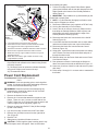
18. Using one of the supplied wire connectors from the
Replacement Part Kit, place one (1) yellow wire from the
new Flicker Motor and the yellow wire cut in step 15 into
each terminal. (Figure 13)
19. Secure the wire connector by crimping the 3M symbol
with pliers.
20. Pull on end of wires to ensure a strong connection.
21. Repeat the process for the four (4) remaining wires.
Ensure that all wires are paired by color in each
connector.
! NOTE: In the event that multiple Flicker Motors were
already replaced within unit, or if required wiring has been cut
too short, it may be necessary to replace Flicker Motor and
the attached cable as a whole.
To do so:
i) Follow steps 1 through 12 and 14.
ii) Follow steps 1 through 8 from Partially Reflective
Glass Replacement procedure to remove Partially
Reflective Glass.
iii) Cut all cable ties that bind the Flicker Motor Cable
and other wires together (wires and cable run behind the
Partially Reflective Glass and up the corner of the firebox
to the Remote Control Receiver).
iv) Unplug Flicker Motor Cable from Remote Control
Receiver (Figure 15).
v) Discard defective Flicker Motor and cable.
vi) Plug in the replacement Flicker Motor into Remote
Control Receiver and run cable down back corner of the
firebox, using cable clamps and ties as needed.
vii) Properly orient and attach new Flicker Motor to
bracket using screws from step 14.
vii) Re-install Partially Reflective Glass and continue
with step 23 below.
22. Properly orient and secure the replacement Flicker Motor
to the bracket with screws removed in step 14.
23. Push smaller opening of rubber sleeve from
Replacement Part Kit onto the Flicker Motor shaft.
24. Push larger end of replacement Flicker Rod into open
end of rubber sleeve.
25. Move plastic bushing from old to new Flicker Rod in the
same position and slide rod into support bracket. Turn
bushing to lock into place.
26. Follow steps 1 through 8 in reverse order to re-assemble
firebox.
Lower Light Harness
Replacement
Tools Required: Phillips head Screwdriver
Wire Cutters
Warning: If unit was operating prior to servicing allow
at least 10 minutes for light bulbs and heating element to
cool off to avoid accidental burning of skin.
Warning: Disconnect power before attempting any
maintenance or cleaning to reduce the risk of electric
shock or damage to persons.
1. Slide firebox out of mantel.
2. Lay unit on it’s back for safe removal of Front Glass.
3. Remove four (4) Phillips screws from right side of trim
(Figure 8).
4. Remove Trim.
5. Slide glass to right side of firebox to remove.
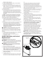
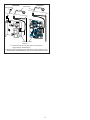
Figure 12
Remaining Spring
on Rod
Figure 13
CAUTION: Even though the glass is safety glass it may
break if bumped, struck of dropped. Care must be taken
when handling the glass.
6. Pull the front edge of the plastic Ember Bed or plastic
grate up and forward until the rear tab releases from the
ledge located at the bottom of the Partially Reflective
Glass (Figure 6).
! IMPORTANT: Only handle the Log Set Assembly by the
Ember Bed or plastic grate.
! NOTE: Log Set Assembly fits tightly into firebox, some
force may be necessary to remove.
7. Disconnect LED harness (only required on DF3015 unit).
8. Set Log Set Assembly in front of firebox.
9. Loosen, but do not remove, the two (2) Philips screws
that clamp the Partially Reflective Glass in place, and
Ensure that all
connectors have
two wires with the
same color
13