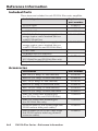
1
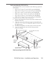
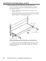
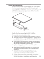
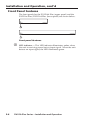
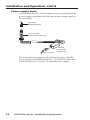
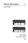
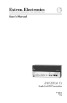
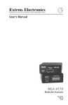
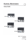
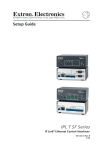
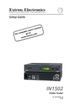
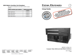
User’s Guide
DVI DA Plus Series
DVI Distribution Amplifiers
68-1536-01
Rev. B
04 09
Precautions
Safety Instructions • English
This symbol is intended to alert the user of important
operating and maintenance (servicing) instructions in
the literature provided with the equipment.
This symbol is intended to alert the user of the
presence of uninsulated dangerous voltage within
the product’s enclosure that may present a risk of
electric shock.
Caution
Read Instructions • Read and understand all safety and operating
instructions before using the equipment.
Retain Instructions • The safety instructions should be kept for future
reference.
Follow Warnings • Follow all warnings and instructions marked on the
equipment or in the user information.
Avoid Attachments • Do not use tools or attachments that are not
recommended by the equipment manufacturer because they may be
hazardous.
Consignes de Sécurité • Français
Ce symbole sert à avertir l’utilisateur que la
documentation fournie avec le matériel contient des
instructions importantes concernant l’exploitation et
la maintenance (réparation).
Ce symbole sert à avertir l’utilisateur de la présence
dans le boîtier de l’appareil de  tensions dangereuses
non isolées posant des risques d’électrocution.
Attention
Lire les instructions• Prendre connaissance de toutes les consignes de
sécurité et d’exploitation avant d’utiliser le matériel.
Conserver les instructions• Ranger les consignes de sécurité afin de pouvoir
les consulter à l’avenir.
Respecter les avertissements • Observer tous les avertissements et consignes
marqués sur le matériel ou présentés dans la documentation utilisateur.
Eviter les pièces de fixation • Ne pas utiliser de pièces de fixation ni d’outils
non recommandés par le fabricant du matériel car cela risquerait de poser
certains dangers.
Sicherheitsanleitungen • Deutsch
Dieses Symbol soll dem Benutzer in der im
Lieferumfang enthaltenen Dokumentation
besonders wichtige Hinweise zur Bedienung und
Wartung (Instandhaltung) geben.
Dieses Symbol soll den Benutzer darauf aufmerksam
machen, daß im Inneren des Gehäuses dieses
Produktes gefährliche Spannungen, die nicht isoliert
sind und die einen elektrischen Schock verursachen
können, herrschen.
Achtung
Lesen der Anleitungen • Bevor Sie das Gerät zum ersten Mal verwenden,
sollten Sie alle Sicherheits-und Bedienungsanleitungen genau durchlesen
und verstehen.
Aufbewahren der Anleitungen • Die Hinweise zur elektrischen Sicherheit
des Produktes sollten Sie aufbewahren, damit Sie im Bedarfsfall darauf
zurückgreifen können.
Befolgen der Warnhinweise • Befolgen Sie alle Warnhinweise und
Anleitungen auf dem Gerät oder in der Benutzerdokumentation.
Keine Zusatzgeräte • Verwenden Sie keine Werkzeuge oder Zusatzgeräte,
die nicht ausdrücklich vom Hersteller empfohlen wurden, da diese eine
Gefahrenquelle darstellen können.
Instrucciones de seguridad • Español
Este símbolo se utiliza para advertir al usuario
sobre instrucciones importantes de operación y
mantenimiento (o cambio de partes) que se desean
destacar en el contenido de la documentación
suministrada con los equipos.
Este símbolo se utiliza para advertir al usuario sobre
la presencia de elementos con voltaje peligroso sin
protección aislante, que puedan encontrarse dentro
de la caja o alojamiento del producto, y que puedan
representar riesgo de electrocución.
Precaucion
Leer las instrucciones • Leer y analizar todas las instrucciones de operación y
seguridad, antes de usar el equipo.
Conservar las instrucciones • Conservar las instrucciones de seguridad para
futura consulta.
Obedecer las advertencias • Todas las advertencias e instrucciones marcadas
en el equipo o en la documentación del usuario, deben ser obedecidas.
Evitar el uso de accesorios • No usar herramientas o accesorios que no
sean especificamente recomendados por el fabricante, ya que podrian
implicar riesgos.
Warning
Power sources • This equipment should be operated only from the power source
indicated on the product. This equipment is intended to be used with a main power
system with a grounded (neutral) conductor. The third (grounding) pin is a safety
feature, do not attempt to bypass or disable it.
Power disconnection • To remove power from the equipment safely, remove all power
cords from the rear of the equipment, or the desktop power module (if detachable),
or from the power source receptacle (wall plug).
Power cord protection • Power cords should be routed so that they are not likely to be
stepped on or pinched by items placed upon or against them.
Servicing • Refer all servicing to qualified service personnel. There are no userserviceable parts inside. To prevent the risk of shock, do not attempt to service
this equipment yourself because opening or removing covers may expose you to
dangerous voltage or other hazards.
Slots and openings • If the equipment has slots or holes in the enclosure, these are
provided to prevent overheating of sensitive components inside. These openings
must never be blocked by other objects.
Lithium battery • There is a danger of explosion if battery is incorrectly
replaced. Replace it only with the same or equivalent type recommended by
the manufacturer. Dispose of used batteries according to the manufacturer’s
instructions.
Avertissement
Alimentations• Ne faire fonctionner ce matériel qu’avec la source d’alimentation
indiquée sur l’appareil. Ce matériel doit être utilisé avec une alimentation principale
comportant un fil de terre (neutre). Le troisième contact (de mise à la terre) constitue
un dispositif de sécurité : n’essayez pas de la contourner ni de la désactiver.
Déconnexion de l’alimentation• Pour mettre le matériel hors tension sans danger,
déconnectez tous les cordons d’alimentation de l’arrière de l’appareil ou du module
d’alimentation de bureau (s’il est amovible) ou encore de la prise secteur.
Protection du cordon d’alimentation • Acheminer les cordons d’alimentation de
manière à ce que personne ne risque de marcher dessus et à ce qu’ils ne soient pas
écrasés ou pincés par des objets.
Réparation-maintenance • Faire exécuter toutes les interventions de réparationmaintenance par un technicien qualifié. Aucun des éléments internes ne peut être
réparé par l’utilisateur. Afin d’éviter tout danger d’électrocution, l’utilisateur ne doit
pas essayer de procéder lui-même à ces opérations car l’ouverture ou le retrait des
couvercles risquent de l’exposer à de hautes tensions et autres dangers.
Fentes et orifices • Si le boîtier de l’appareil comporte des fentes ou des orifices, ceux-ci
servent à empêcher les composants internes sensibles de surchauffer. Ces ouvertures
ne doivent jamais être bloquées par des objets.
Lithium Batterie • Il a danger d’explosion s’ll y a remplacment incorrect de la batterie.
Remplacer uniquement avec une batterie du meme type ou d’un ype equivalent
recommande par le constructeur. Mettre au reut les batteries usagees conformement
aux instructions du fabricant.
Vorsicht
Stromquellen • Dieses Gerät sollte nur über die auf dem Produkt angegebene
Stromquelle betrieben werden. Dieses Gerät wurde für eine Verwendung mit einer
Hauptstromleitung mit einem geerdeten (neutralen) Leiter konzipiert. Der dritte
Kontakt ist für einen Erdanschluß, und stellt eine Sicherheitsfunktion dar. Diese
sollte nicht umgangen oder außer Betrieb gesetzt werden.
Stromunterbrechung • Um das Gerät auf sichere Weise vom Netz zu trennen, sollten
Sie alle Netzkabel aus der Rückseite des Gerätes, aus der externen Stomversorgung
(falls dies möglich ist) oder aus der Wandsteckdose ziehen.
Schutz des Netzkabels • Netzkabel sollten stets so verlegt werden, daß sie nicht im
Weg liegen und niemand darauf treten kann oder Objekte darauf- oder unmittelbar
dagegengestellt werden können.
Wartung • Alle Wartungsmaßnahmen sollten nur von qualifiziertem Servicepersonal
durchgeführt werden. Die internen Komponenten des Gerätes sind wartungsfrei.
Zur Vermeidung eines elektrischen Schocks versuchen Sie in keinem Fall, dieses
Gerät selbst öffnen, da beim Entfernen der Abdeckungen die Gefahr eines
elektrischen Schlags und/oder andere Gefahren bestehen.
Schlitze und Öffnungen • Wenn das Gerät Schlitze oder Löcher im Gehäuse aufweist,
dienen diese zur Vermeidung einer Überhitzung der empfindlichen Teile im
Inneren. Diese Öffnungen dürfen niemals von anderen Objekten blockiert werden.
Litium-Batterie • Explosionsgefahr, falls die Batterie nicht richtig ersetzt
wird. Ersetzen Sie verbrauchte Batterien nur durch den gleichen oder einen
vergleichbaren Batterietyp, der auch vom Hersteller empfohlen wird. Entsorgen Sie
verbrauchte Batterien bitte gemäß den Herstelleranweisungen.
Advertencia
Alimentación eléctrica • Este equipo debe conectarse únicamente a la fuente/tipo
de alimentación eléctrica indicada en el mismo. La alimentación eléctrica de este
equipo debe provenir de un sistema de distribución general con conductor neutro
a tierra. La tercera pata (puesta a tierra) es una medida de seguridad, no puentearia
ni eliminaria.
Desconexión de alimentación eléctrica • Para desconectar con seguridad la acometida
de alimentación eléctrica al equipo, desenchufar todos los cables de alimentación
en el panel trasero del equipo, o desenchufar el módulo de alimentación (si fuera
independiente), o desenchufar el cable del receptáculo de la pared.
Protección del cables de alimentación • Los cables de alimentación eléctrica se deben
instalar en lugares donde no sean pisados ni apretados por objetos que se puedan
apoyar sobre ellos.
Reparaciones/mantenimiento • Solicitar siempre los servicios técnicos de personal
calificado. En el interior no hay partes a las que el usuario deba acceder. Para evitar
riesgo de electrocución, no intentar personalmente la reparación/mantenimiento
de este equipo, ya que al abrir o extraer las tapas puede quedar expuesto a voltajes
peligrosos u otros riesgos.
Ranuras y aberturas • Si el equipo posee ranuras o orificios en su caja/alojamiento,
es para evitar el sobrecalientamiento de componentes internos sensibles. Estas
aberturas nunca se deben obstruir con otros objetos.
Batería de litio • Existe riesgo de explosión si esta batería se coloca en la posición
incorrecta. Cambiar esta batería únicamente con el mismo tipo (o su equivalente)
recomendado por el fabricante. Desachar las baterías usadas siguiendo las
instrucciones del fabricante.
安全须知 • 中文
警告
这个符号提示用户该设备用户手册中
有重要的操作和维护说明。
电源 • 该 设 备 只 能 使 用 产 品 上 标 明 的 电 源 。 设 备
必须使用有地线的供电系统供电。 第三条线
(地线)是安全设施,不能不用或跳过。
这个符号警告用户该设备机壳内有暴
拔掉电源 • 为安全地从设备拔掉电源,请拔掉所有设备后
或桌面电源的电源线,或任何接到市电系统的电源线。
露的危险电压,有触电危险。
电源线保护 • 妥善布线, 避免被踩踏,或重物挤压。
注意
阅读说明书 • 用 户 使 用 该 设 备 前 必 须 阅 读 并 理
解所有安全和使用说明。
保存说明书 • 用户应保存安全说明书以备将来使
用。
遵守警告 • 用户应遵守产品和用户指南上的所有安
全和操作说明。
维护 • 所有维修必须由认证的维修人员进行。 设备内部
没有用户可以更换的零件。为避免出现触电危险不要自
己试图打开设备盖子维修该设备。
通风孔 • 有些设备机壳上有通风槽或孔,它们是用来防止
机内敏感元件过热。 不要用任何东西挡住通风孔。
锂电池 • 不正确的更换电池会有爆炸的危险。 必须使用
与厂家推荐的相同或相近型号的电池。 按照生产厂的
建议处理废弃电池。
避免追加 • 不要使用该产品厂商没有推荐的工具或
追加设备,以避免危险。
声明
所使用电源为 A 级产品,在生活环境中,该产品可能会造成无线电干扰。在这种情况下,可能需要用
户对其干扰采取切实可行的措施。
FCC Class A Notice
This equipment has been tested and found to comply with the limits for a Class A digital device,
pursuant to part 15 of the FCC Rules. Operation is subject to the following two conditions: (1) this
device may not cause harmful interference, and (2) this device must accept any interference received,
including interference that may cause undesired operation. The Class A limits are designed to
provide reasonable protection against harmful interference when the equipment is operated in
a commercial environment. This equipment generates, uses, and can radiate radio frequency
energy and, if not installed and used in accordance with the instruction manual, may cause harmful
interference to radio communications. Operation of this equipment in a residential area is likely to
cause harmful interference, in which case the user will be required to correct the interference at his
own expense.
N
This unit was tested with shielded cables on the peripheral devices. Shielded cables must be used
with the unit to ensure compliance with FCC emissions limits.
N For complete safety information about these products please read the Safety
Compliances sheet, which is available online at www.extron.com.
Table of Contents
Chapter One • Introduction..................................................... 1-1
About This Manual.................................................................... 1-2
About the DVI DA Plus Series. ............................................... 1-2
DVI DA Plus Series Features.................................................... 1-3
Chapter Two • Installation and Operation. .................. 2-1
Installation Overview. .............................................................. 2-2
Mounting the Distribution Amplifier.................................. 2-2
Tabletop placement................................................................ 2-2
Rack mounting........................................................................ 2-2
UL guidelines for rack mounting............................................2-2
Rack mounting the DVI DA4 Plus...........................................2-3
Rack mounting the DVI DA6 Plus and DVI DA8 Plus.............2-4
Under-desk mounting............................................................. 2-5
Front Panel Features.................................................................. 2-6
Rear Panel Features................................................................... 2-7
Power supply input................................................................. 2-8
Input cable connections.......................................................... 2-9
Output cable connections...................................................... 2-9
DVI connector pin assignments........................................... 2-10
Operation.................................................................................... 2-11
Troubleshooting........................................................................ 2-12
Appendix A • Reference Information .............................A-1
Specifications...............................................................................A-2
Included Parts..............................................................................A-4
Accessories. ..................................................................................A-4
All trademarks mentioned in this manual are the properties of their respective owners.
68-1536-01
Rev. B
04 09
DVI DA Plus Series • Table of Contents
i
Table of Contents, cont’d
ii
DVI DA Plus Series • Table of Contents
DVI DA Plus Series
1
Chapter One
Introduction
About this manual
About the DVI DA Plus Series
DVI DA Plus Series Features
Introduction
About This Manual
This manual describes the installation, operation, and
specifications of the Extron DVI DA4 Plus, DVI DA6 Plus, and
DVI DA8 Plus Distribution Amplifiers.
Unless stated otherwise, all references to the "distribution
amplifier" or "DVI DA Plus Series" in this manual refer to the
features or operation of all three models.
About the DVI DA Plus Series
These Digital Visual Interface (DVI) Distribution Amplifiers
(DAs) accept one single link DVI-D input and distribute four
(DVI DA4 Plus), six (DVI DA6 Plus), or eight (DVI DA8 Plus)
single link DVI-D output signals.
All three models use Extron's EDID Minder feature to maintain
continuous EDID (Extended Display Identification Data)
communication with the attached source. This ensures that the
DVI source powers up correctly and maintains a proper video
output, even if the display is off.
The DVI DA4 Plus is 1U high and half a rack wide. The
DVI DA6 Plus and DVI DA8 Plus are both 1U high and a full
rack wide. All three models offer a variety of mounting options.
The illustration below shows a typical application of the
DVI DA8 Plus.
us
8 Pl
I DA
DV
8
7
6
5
UT
TP
I-D
DV
OU
4
3
2
1
UT
I-D
INP
DV
Extron
DVI DA8 Plus
R
WE
PO
12V MAX
A
Display
with
DVI Input
0.4
Distribution Amplifier
Computer
with
DVI Output
1-2
DVI DA Plus Series • Introduction
Display
with
DVI Input
Local
Monitor
DVI DA Plus Series Features
EDID Minder — The EDID Minder maintains continuous EDID
(Extended Display Identification Data) communication with
the attached source. This ensures that the DVI source powers
up correctly and maintains a proper video output, even if the
display is off.
High Resolution DVI-D input — The distribution amplifiers
accept one single link DVI-D input, with a resolution range up
to 1920 x 1200 or 1080p @ 60 Hz.
Input Equalization — Input Equalization (EQ) conditions the
input signals to ensure the integrity of the signals delivered to
the output devices.
DVI-D outputs — The units distribute four (DVI DA4 Plus),
six (DVI DA6 Plus), or eight (DVI DA8 Plus) single link DVI-D
output signals simultaneously, at resolutions up to 1920 x 1200
or 1080p @ 60 Hz.
N
The actual signal transmission distance can vary greatly
and depends on signal resolution, cable type, cable
quality, graphics card and the display used in the system.
External power supply — All three models are powered by
external 12 VDC power supply (provided with the units).
Power on Pin 14 — The distribution amplifiers are able to
provide a 5 VDC (250 mA) output.
Front Panel Indicator LED — The LED light on the front panel
provides feedback about power status and whether an input
signal is detected.
Versatile mounting options — All three units can be mounted
in a rack, under a desk or set on a tabletop.
DVI DA Plus Series • Introduction
1-3
Introduction, contd
1-4
DVI DA Plus Series • Introduction
DVI DA Plus Series
2
Chapter Two
Installation and Operation
Installation Overview
Mounting the Distribution Amplifier
Front Panel Features
Rear Panel Features
Operation
Troubleshooting
Installation and Operation
Installation Overview
All three distribution amplifiers can be mounted on tabletops,
under furniture, and in racks by following these steps:
1. Ensure that the input sources, the distribution amplifier and
the output display(s) are all turned off and all power sources
and signal cables are disconnected.
2. Mount the unit as described in "Mounting the Distribution
Amplifier", below.
3. Connect the cables (see page 2-9).
4. Plug in the power supply, turn on the display devices and,
finally, turn on the input devices (see page 2-11).
Mounting the Distribution Amplifier
Tabletop placement
Attach the four provided rubber feet to the bottom of the unit
and place it in any convenient location.
Rack mounting
UL guidelines for rack mounting
The following Underwriters Laboratories (UL) guidelines are
relevant to the safe installation of these products in a rack:
1. Elevated operating ambient temperature — If the unit
is installed in a closed or multi-unit rack assembly, the
operating ambient temperature of the rack environment
may be greater than room ambient temperature. Therefore,
install the equipment in an environment compatible with
the maximum ambient temperature (Tma: +122 °F, +50 °C)
specified by Extron.
2. Reduced air flow — Install the equipment in the rack so that
the equipment gets adequate air flow for safe operation.
3. Mechanical loading — Mount the equipment in the rack so
that uneven mechanical loading does not create a hazardous
condition.
4. Circuit overloading — Connect the equipment to the supply
circuit and consider the effect that circuit overloading might
have on overcurrent protection and supply wiring. Give
appropriate consideration to the equipment nameplate
ratings when addressing this concern.
5. Reliable earthing (grounding) — Maintain reliable
grounding of rack-mounted equipment. Pay particular
attention to supply connections other than direct connections
to the branch circuit (such as the use of power strips).
2-2
DVI DA Plus Series • Installation and Operation
Rack mounting the DVI DA4 Plus
The DVI DA4 Plus can be mounted on the following (optional)
rack shelves:
•
RSF 123 (3.5" deep, 1U rack shelf kit: part # 60-190-20)
•
RSB 123 (3.5" deep, 1U basic rack shelf: part # 60-604-20)
•
RSU 126 (6" deep, 1U rack shelf kit: part # 60-190-10)
•
RSB 126 (6" deep, 1U basic rack shelf: part # 60-604-10)
•
RSU 129 (9.5" deep, 1U rack shelf kit: part # 60-190-01)
•
RSB 129 (9.5" deep, 1U basic rack shelf: part # 60-604-01)
To mount the units, follow these instructions:
1.
Remove the rubber feet if these have been installed on the
bottom of the unit.
2.
Align the unit on the shelf and secure it to the shelf with
two 4-40 x 3/16" screws in diagonally opposite corners (see
the figure below).
3.
Install false faceplate(s) or other unit(s) to the rack shelf.
4.
Attach the shelf to the rack with the four provided
10-32 x 3/4" bolts.
1U Universal Rack Shelf
1/2 Rack Width Front False
Faceplate
Front false
faceplate
uses 2
screws.
Use 2 mounting holes on
opposite corners.
(2) 4-40 x 3/16"
Screws
Rack mounting the DVI DA4 Plus
DVI DA Plus Series • Installation and Operation
2-3
Installation and Operation, cont’d
Rack mounting the DVI DA6 Plus and DVI DA8 Plus
The DVI DA6 Plus and DVI DA8 Plus distribution amplifiers
can be mounted using the Extron MBD 149 rack mount kit
(provided) as follows:
1.
Remove rubber feet if these have been installed on the
bottom of the unit.
2.
Secure one bracket to each side of the distribution amplifier
with the provided bracket mounting screws (four #8 screws
for each bracket — see the figure below).
MBD 149 Bracket
FRONT
Rack mounting screws
Bracket mounting screws
Rack mounting the DVI DA6 Plus or DVI DA8 Plus
3. Align the holes in the mounting brackets with holes in the
rack and secure the unit with brackets to the rack using the
four rack-mounting screws and four washers provided with
the mounting kit.
2-4
DVI DA Plus Series • Installation and Operation
Under-desk mounting
Mount the DVI DA6 Plus or DVI DA8 Plus (not shown) under
furniture, using the optional Extron MBU 149 under-desk
mounting kit (part # 70-222-01). Mount the DVI DA4 Plus using
the optional Extron MBU 123 under-desk mounting kit (part
# 70-212-01) as shown in the figure below. Follow the same
instructions with either kit:
Under furniture mounting the DVI DA4 Plus
To mount the unit under a desk or table:
1. If necessary, remove rubber feet from the bottom of the unit.
2. Secure the under-desk mounting brackets to the unit with the
four (DVI DA4 Plus) or eight (DVI DA6 Plus/DVI DA8 Plus)
provided #8 screws.
3. Hold the unit, with the mounting brackets attached, under
the furniture where it will be secured. Mark the position of
the holes on the underside of the furniture.
4. In the marked positions, drill four pilot holes 3/32" in
diameter and 1/4" deep.
5. Insert the four provided wood screws into the pilot holes
and tighten until approximately 1/4" of the screw head is
protruding.
6. Guide the holes of the mounting brackets over the
protruding screw head and slide the unit forward or
backward to seat it firmly under the furniture.
7. Tighten all four wood screws to secure the unit in place.
DVI DA Plus Series • Installation and Operation
2-5
Installation and Operation, cont’d
Front Panel Features
The front panels for the DVI DA4 Plus (upper panel) and the
DVI DA6 Plus/DVI DA8 Plus (lower panel) are shown below:
DVI DA PLUS
DVI DISTRIBUTION AMPLIFIER
1
DVI DA Plus SERIES
DVI DISTRIBUTION AMPLIFIER
1
Front panel features
a
2-6
LED indicator — This LED indicator illuminates amber when
the unit is receiving power but no input signal. When the unit
detects an input signal, the LED illuminates green.
DVI DA Plus Series • Installation and Operation
Rear Panel Features
The rear panels for the DVI DA4 Plus (top panel), the
DVI DA6 Plus (middle panel), and DVI DA8 Plus (bottom
panel) are shown below:
DVI DA4 Plus
POWER
12V
1.0A MAX
DVI-D INPUT
2
3
DVI-D OUTPUT
1
2
3
4
4
DVI DA6 Plus
POWER
12V
1.5A MAX
2
DVI-D OUTPUT
DVI-D INPUT
1
2
3
3
4
5
6
5
6
4
DVI DA8 Plus
POWER
12V
1.5A MAX
DVI-D OUTPUT
DVI-D INPUT
1
2
3
4
7
8
Rear panel features
b
c
d
Power input — Connect the external power supply (provided)
to the 3.5 mm, 2-pole captive screw power receptacle.
Input connector — Connect the input signal to the female DVI-I
connector. The DVI input signal is equalized to ensure integrity.
Output Connectors — Connect up to four (DVI DA4 Plus),
six (DVI DA6 Plus) or eight (DVI DA8 Plus) DVI-D outputs to
display devices, using the female DVI-I connectors.
N
Although these distribution amplifiers have DVI-I
connectors, they are only compatible with single link
DVI-D video signals.
N
The DVI DA Plus series distribution amplifiers are not
HDCP compliant.
DVI DA Plus Series • Installation and Operation
2-7
Installation and Operation, cont’d
Power supply input
Connect the two pole, 3.5 mm captive screw connector from the
power supply (provided with the unit) to this orange socket on
the rear panel.
POWER
12V
1.0A MAX
Back Panel
Power Receptacle
DC Power Cord
Captive Screw Connector
Ground
+12 VDC
AC Power Cord
External
Power Supply
(12 VDC, 2 A )
The external power supply in the illustration above (12 VDC,
2A) is for use with the DVI DA4 Plus. The DVI DA6 Plus and
DVI DA8 Plus use a 12 VDC, 3A external power supply.
2-8
DVI DA Plus Series • Installation and Operation
Input cable connections
Connect a single link DVI-D source device, with a resolution
range up to 1920 x1200 or 1080p @ 60 Hz, to the female DVI-I
input, using a DVI cable.
N
Although these distribution amplifiers have DVI-I
connectors, they are only compatible with single link
DVI-D video signals.
Input EQ conditions input signals to ensure the integrity of the
signals delivered to the output devices.
Output cable connections
Use DVI-I cables to connect up to four (DVI DA4 Plus),
six (DVI DA6 Plus) or eight (DVI DA8 Plus) display devices.
N
The actual signal transmission distance can vary and
depends on signal resolution, cable quality, graphics
card, and display used in the system.
DVI DA Plus Series • Installation and Operation
2-9
Installation and Operation, cont’d
DVI connector pin assignments
The illustration below shows the pin assignments for the
DVI-I connectors.
N
Although DVI-I dual link connectors are used, these
distribution amplifiers are only compatible with single
link DVI-D video signals.
DVI - Female
1
8
17
24
9
2-10
Pin
Signal
Pin
Signal
Pin
Signal
1
TMDS data 2–
9
TMDS data 1–
17
TMDS data 0–
2
TMDS data 2+
10
TMDS data 1+
18
TMDS data 0+
3
TMDS data
2/4 shield
11
TMDS data
1/3 shield
19
TMDS data
0/5 shield
4
Spare
12
Spare
20
Spare
5
Spare
13
Spare
21
Spare
6
DDC clock
14
+5 V power
22
TMDS clock
shield
7
DDC data
15
Ground
23
TMDS clock+
8
Spare
16
Hot plug detect
24
TMDS clock–
DVI DA Plus Series • Installation and Operation
Operation
1.
Connect the captive screw connector from the supplied
12 VDC power supply into the power receptacle on the
rear panel. Do not power on the power supply yet.
2.
Connect the source device to the DVI input receptacle on
the rear panel.
3.
Run cables from the display device(s) and connect them to
the DVI output receptacles on the rear panel.
4.
Power on the display device(s).
5.
Power on the distribution amplifier. The LED will light
amber to show that the unit is receiving power.
6.
Power on the input device.
When a DVI video source boots up it normally communicates
with the output device using the bi-directional Extended
Display Identification Data (EDID) communication protocol.
The output device then produces a signal with a resolution that
is compatible with the output device.
Extron's EDID Minder feature maintains continuous EDID
(Extended Display Identification Data) communication with
the attached source and ensures that the DVI source powers
up correctly and maintains a proper video output, even if the
display is off or when a new monitor is connected to the output.
When the distribution amplifier is powered on, it automatically
scans all detectable outputs, selects the device with the lowest
native resolution and passes the EDID information of that
device to the input device.
If no output displays are connected, the distribution amplifier
provides the EDID information stored from the last display to
which it was connected. If no output device has previously
been connected to the unit, or the unit has been set to the factory
default, it uses the factory default resolution (1024 x 768).
DVI DA Plus Series • Installation and Operation
2-11
Installation and Operation, cont’d
Troubleshooting
No output signal — Check that the front panel LED is on
(amber shows that the unit is receiving power, green shows that
it is also receiving an input signal). If LED is not lit, check the
power supply and/or video input connections to the unit (see
page 2-6).
No output signal or poor quality signal — Check the integrity
of the cabling from the source device to the distribution
amplifier and from the distribution amplifier to each of the
display devices.
DVI signals run at very high frequency and poor connections
can cause degradation or loss of the signal, or jitter.
• Signal transmission distance can vary greatly and depends
on signal resolution, cable type, cable quality, graphics card
and the display used in the system.
• Use only cable that is designed for DVI signals.
• Limit or avoid the use of adapters or couplers.
Display device displays a flashing black or blue screen, snow
or other distortion — A device that is not HDCP compliant may
be receiving HDCP-encrypted signals.
The DVI DA Plus series distribution amplifiers are not
High-Bandwidth Digital Content Protection (HDCP) compliant.
Signal on some displays but not others — Reboot the source
device.
When the source device boots up, the distribution amplifier's
EDID handling feature ensures that the output resolution of
the source device is matched to the requirements of the display
device with the lowest resolution.
If an additional display device is added, which requires an even
lower resolution, the image will not be displayed correctly on
that monitor until the source device is shut down and rebooted.
At that time, the distribution amplifier's EDID handling ensures
that the output resolution of the source device is recalibrated to
meet the needs of the additional display device.
2-12
DVI DA Plus Series • Installation and Operation
DVI DA Plus Series
A
Appendix A
Reference Information
Specifications
Included Parts
Accessories
Reference Information
Specifications
N
*Appropriate DVI-D to HDMI cables or adapters are required
for HDMI signal input/output.
Video
Maximum data rate....................... 4.95 Gbps (1.65 Gbps per color)
Maximum pixel clock.................... 165 MHz
Resolution Range........................... Up to 1920 x 1200 or 1080p @ 60 Hz
Formats............................................ RGB and YCbCr digital video
Standards......................................... DVI 1.0, HDMI 1.2
Video Input
Numbers/signal type.................... 1 single link DVI-D (or HDMI*)
Connectors...................................... 1 female DVI-I
Video Output
Numbers/signal type.................... 4, 6 or 8 (depending on model) single link
DVI-D (or HDMI*)
Connectors...................................... 4, 6 or 8 female DVI-I
General
External power supply.................. 100 VAC to 240 VAC, 50/60 Hz, external;
to 12 VDC, regulated
DVI DA4 Plus..................... 2 A
DVI DA6 Plus, DVI DA8 Plus
3A
Power input requirements............ 12 VDC
DVI DA4 Plus..................... 1.0 A (max)
DVI DA6 Plus, DVI DA8 Plus
1.5 A (max)
Temperature/humidity................. Storage - 40° to + 158°F (-40° to + 70°C) /
10% to 90%, noncondensing
Operating + 32° to + 122°F (0° to + 50°C) /
10% to 90%, noncondensing
Cooling............................................ Convection, no vents
Mounting
Rack mount......................... Yes, with optional shelf kits or basic
shelves (DVI DA4 Plus)
or with provided mounting brackets (DVI
DA6 Plus and DVI DA8 Plus)
Furniture mount................. Yes with optional under-desk mounting
kit
A-2
DVI DA Plus Series • Reference Information
Enclosure type................................ Metal
Enclosure dimensions
DVI DA4 Plus.....................1.75" H x 8.75" W x 3.0" D
(1U high, half rack wide)
4.4 cm H x 22.2 cm W x 7.6 cm D
(Depth excludes connectors.)
DVI DA6 Plus, DVI DA8 Plus
1.75" H x 17.5" W x 8.5" D
(1U high, full rack wide)
4.4 cm H x 44.4 cm W x 21.6 cm D
(Depth excludes connectors.)
Product weight............................... 2.8 lbs (1.3 kg)
Shipping weight............................. 5 lbs (3 kg)
Vibration.......................................... ISTA 1A in carton (International Safe
Transit Association)
Regulatory compliance
Safety.................................... CE, CUL, UL
EMI/EMC........................... CE, C-tick, FCC Class A, ICES, VCCI
MTBF................................................ 30,000 hours
Warranty.......................................... 3 years parts and labor
N
All nominal levels are at ±10%
N
Specifications are subject to change without notice
DVI DA Plus Series • Reference Information
A-3
Reference Information
Included Parts
These items are included in each DVI DA Plus series amplifier:
Included parts
Replacement
part number
DVI DA4 Plus
60-846-01
DVI DA6 Plus
60-932-01
or DVI DA8 Plus
60-933-01
12 VDC, 2A Desktop power supply with
orange captive screw attached (for use
with DVI DA4 Plus)
28-181-05LF
12 VDC, 3A Desktop power supply with
orange captive screw attached (for use
with DVI DA6 Plus and DVI DA8 Plus)
28-113-05LF
(1) IEC cord
(4) Rubber feet (not attached)
MBD 149 rack mount kit
(DVI DA6 Plus and DVI DA8 Plus only)
70-770-03
Setup Guide — DVI DA Plus Series
Accessories
Accessories
A-4
Part number
RSF 123 (3.5" deep, 1U rack shelf kit)
60-190-20
RSB 123 (3.5" deep, 1U basic rack shelf)
60-604-20
RSU 126 (6" deep, 1U rack shelf kit)
60-190-10
RSB 126 (6" deep, 1U basic rack shelf)
60-604-10
RSU 129 (9.5" deep, 1U rack shelf kit)
60-190-01
RSB 129 (9.5" deep, 1U basic rack shelf)
60-604-01
MBU 149 Under desk mounting kit
(for DVI DA6 Plus and DVI DA8 Plus)
70-222-01
MBU 123 Under desk mounting kit
(for DVI DA4 Plus only)
70-212-01
DVID SL series (3, 6 or 15 feet single link
DVI-D male to male patch cables)
26-585-0x
IN9700 series (25, 35, 50 or 75 feet single
link DVI-D male to male long distance
extension cables)
26-584-0x
DVI DA Plus Series • Reference Information
Extron’s Warranty
Extron Electronics warrants this product against defects in materials and workmanship
for a period of three years from the date of purchase. In the event of malfunction during
the warranty period attributable directly to faulty workmanship and/or materials,
Extron Electronics will, at its option, repair or replace said products or components,
to whatever extent it shall deem necessary to restore said product to proper operating
condition, provided that it is returned within the warranty period, with proof of
purchase and description of malfunction to:
USA, Canada, South America,
and Central America:
Extron USA
1001 East Ball Road
Anaheim, CA 92805
U.S.A.
Europe, Africa, and the Middle East:
Extron Europe
Hanzeboulevard 10
3825 PH Amersfoort
The Netherlands
Asia:
Extron Asia
135 Joo Seng Road #04-01
PM Industrial Bldg.
Singapore 368363
Singapore
Japan:
Extron Japan
Kyodo Building, 16 Ichibancho
Chiyoda-ku, Tokyo 102-0082
Japan
China:
Extron China
686 Ronghua Road
Songjiang District
Shanghai 201611
China
Middle East:
Extron Middle East
Dubai Airport Free Zone
F12, PO Box 293666
United Arab Emirates, Dubai
This Limited Warranty does not apply if the fault has been caused by misuse, improper
handling care, electrical or mechanical abuse, abnormal operating conditions or nonExtron authorized modification to the product.
If it has been determined that the product is defective, please call Extron and ask for an
Applications Engineer at (714) 491-1500 (USA), 31.33.453.4040 (Europe), 65.6383.4400
(Asia), or 81.3.3511.7655 (Japan) to receive an RA# (Return Authorization number). This
will begin the repair process as quickly as possible.
Units must be returned insured, with shipping charges prepaid. If not insured, you
assume the risk of loss or damage during shipment. Returned units must include the
serial number and a description of the problem, as well as the name of the person to
contact in case there are any questions.
Extron Electronics makes no further warranties either expressed or implied with respect
to the product and its quality, performance, merchantability, or fitness for any particular
use. In no event will Extron Electronics be liable for direct, indirect, or consequential
damages resulting from any defect in this product even if Extron Electronics has been
advised of such damage.
Please note that laws vary from state to state and country to country, and that some
provisions of this warranty may not apply to you.
Extron USA - West
Headquarters
+800.633.9876
Inside USA / Canada Only
+1.714.491.1500
+1.714.491.1517 FAX
Extron USA - East
Extron Europe
Extron Asia
Extron Japan
Extron China
Extron Middle East
+800.633.9876
+800.3987.6673
+800.7339.8766
+81.3.3511.7655
+81.3.3511.7656 FAX
+400.883.1568
+971.4.2991800
+971.4.2991880 FAX
+1.919.863.1794
+1.919.863.1797 FAX
+31.33.453.4040
+31.33.453.4050 FAX
+65.6383.4400
+65.6383.4664 FAX
Inside USA / Canada Only
Inside Europe Only
Inside Asia Only
© 2009 Extron Electronics. All rights reserved.
Inside China Only
+86.21.3760.1568
+86.21.3760.1566 FAX