1
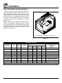
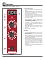
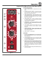
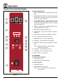
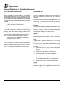
ZEPHAIRE-E & zephaire-E plus
convection ovens
INSTALLATION - OPERATION - MAINTENANCE
BLODGETT OVEN COMPANY
www.blodgett.com
44 Lakeside Avenue, Burlington, Vermont 05401 USA Telephone: (802) 658-6600 Fax: (802) 864-0183
PN 90147 Rev V (10/13)
© 2013 - G.S. Blodgett Corporation
Your Service Agency’s Address:
Model
Serial number
Oven installed by
Installation checked by
TABLE OF CONTENTS
IMPORTANT
WARNING: Improper installation, adjustment, alternation,
service or maintenance can
cause property damage, injury or death. Read the instllation, operation and maintenance instructions thoroughly
before installing or servicing
this equipment.
FOR YOUR SAFETY
Do not store or use gasoline or
other flammable vapors or liquids in the vicinity of this or any
other appliance.
The information contained in this
manual is important for the proper installation, use, and maintenance of this oven. Adherence
to these procedures and instructions will result in satisfactory
baking results and long, trouble free service. Please read
this manual carefully and retain
it for future reference.
ERRORS: Descriptive, typographic or pictorial errors are
subject to correction. Specifications are subject to change
without notice.
INSTALLATION
Oven Description and Specifications. . . . . . . . . . . . . . . . . . . . . . . . . . . . . . . . . . . . . . . . 2
Delivery and Location. . . . . . . . . . . . . . . . . . . . . . . . . . . . . . . . . . . . . . . . . . . . . . . . . . . . . 3
Utility Connections - Standards and Codes. . . . . . . . . . . . . . . . . . . . . . . . . . . . . . . . . . 4
Electric and Water Connections. . . . . . . . . . . . . . . . . . . . . . . . . . . . . . . . . . . . . . . . . . . . 5
Oven Assembly. . . . . . . . . . . . . . . . . . . . . . . . . . . . . . . . . . . . . . . . . . . . . . . . . . . . . . . . . . . 6
NSF Bolts. . . . . . . . . . . . . . . . . . . . . . . . . . . . . . . . . . . . . . . . . . . . . . . . . . . . . . . . . . . . 6
Leg Attachment. . . . . . . . . . . . . . . . . . . . . . . . . . . . . . . . . . . . . . . . . . . . . . . . . . . . . . . 7
Caster Assembly. . . . . . . . . . . . . . . . . . . . . . . . . . . . . . . . . . . . . . . . . . . . . . . . . . . . . . 7
Double Section Assembly. . . . . . . . . . . . . . . . . . . . . . . . . . . . . . . . . . . . . . . . . . . . . . 8
Oven Leveling. . . . . . . . . . . . . . . . . . . . . . . . . . . . . . . . . . . . . . . . . . . . . . . . . . . . . . . . 8
OPERATION
Zephaire E Standard Control. . . . . . . . . . . . . . . . . . . . . . . . . . . . . . . . . . . . . . . . . . . . . . . 9
Zephaire E Plus Standard Control. . . . . . . . . . . . . . . . . . . . . . . . . . . . . . . . . . . . . . . . . 10
Zephaire E Plus Manual Control with Water Spritzer.. . . . . . . . . . . . . . . . . . . . . . . . 11
Zephaire E Plus Solid State Digital.. . . . . . . . . . . . . . . . . . . . . . . . . . . . . . . . . . . . . . . . 12
General Guidelines for Operating Personnel. . . . . . . . . . . . . . . . . . . . . . . . . . . . . . . . 14
Suggested Times and Temperatures. . . . . . . . . . . . . . . . . . . . . . . . . . . . . . . . . . . . . . . 15
MAINTENANCE
Cleaning and Preventative Maintenance. . . . . . . . . . . . . . . . . . . . . . . . . . . . . . . . . . . 16
Troubleshooting Guide. . . . . . . . . . . . . . . . . . . . . . . . . . . . . . . . . . . . . . . . . . . . . . . . . . . 17
Installation
Oven Description and Specifications
Cooking in a convection oven differs from cooking in a
conventional deck or range oven since heated air is constantly recirculated over the product by a fan in an enclosed chamber. The moving air continually strips away
the layer of cool air surrounding the product, quickly allowing the heat to penetrate. The result is a high quality product, cooked at a lower temperature in a shorter
amount of time.
Blodgett convection ovens represent the latest advancement in energy efficiency, reliability, and ease of operation. Heat normally lost, is recirculated within the cooking
chamber before being vented from the oven: resulting in
substantial reductions in energy consumption and enhanced oven performance.
Air Flow Pattern for Blodgett Electric Convection Ovens
Figure 1
voltage
hz
kW
electrical ratings
max load (amps)
Phase
L1
L2
L2
208
60
11
1
51
0
51
208
60
11
3
31
29
29
220-240
60
11
1
44
0
44
220-240
60
11
3
26
24
24
440
60
11
3
15
14
14
480
60
11
3
14
13
13
220/380
60
11
3
18
15
15
220/380
50
11
3
18
15
15
240/415
50
11
3
18
14
14
230/400
50
11
3
18
15
15
* Electric connection wiring is sized for 90ºC copper wire at 125% of rated input.
2
N
—
—
—
—
—
—
3
3
4
3
Electrical
Connection
AWG*
6
8
6
8
12
12
Size per local code
Size per local code
Size per local code
Size per local code
Installation
Delivery and Location
Delivery and inspection
oven location
All Blodgett ovens are shipped in containers to prevent
damage. Upon delivery of your new oven:
The well planned and proper placement of your oven will
result in long term operator convenience and satisfactory
performance.
•
Inspect the shipping container for external damage.
Any evidence of damage should be noted on the
delivery receipt which must be signed by the driver.
•
Uncrate the oven and check for internal damage.
Carriers will accept claims for concealed damage if
notified within fifteen days of delivery and the shipping container is retained for inspection.
The following clearances must be maintained between
the oven and any combustible or non-combustible construction.
The Blodgett Oven Company cannot assume responsibility for loss or damage suffered in transit. The carrier assumed full responsibility for delivery in good order when
the shipment was accepted. We are, however, prepared
to assist you if filing a claim is necessary.
•
Oven body right side - 1/2” (1.3 cm)
•
Oven body left side - 1/2” (1.3 cm)
•
Oven body back - 1/2” (1.3 cm)
•
Oven body bottom - 1/2” (1.3 cm)
Adequate clearances must be available for servicing.
•
Keep the oven area free and clear of all combustibles such as paper, cardboard, and flammable
liquids and solvents.
•
Do not place the oven on a curb base or seal to
a wall. This will restrict the flow of air and prevent
proper ventilation resulting in damage to the oven.
Before making any utility connections to this oven, check
the rating plate to be sure the oven specifications are
compatible with the electrical services supplied for the
oven.
1. The rating plate is attached on the oven body back.
3
Installation
Utility Connections - Standards and Codes
U.S. and Canadian installations
THE INSTALLATION INSTRUCTIONS CONTAINED
HEREIN ARE FOR THE USE OF QUALIFIED INSTALLATION AND SERVICE PERSONNEL ONLY. INSTALLATION OR SERVICE BY OTHER THAN QUALIFIED
PERSONNEL MAY RESULT IN DAMAGE TO THE OVEN
AND/OR INJURY TO THE OPERATOR.
Installation must conform with local codes, or in the absence of local codes, with the National Electrical Code,
ANSI/NFPA 70-Latest Edition and/or Canadian National
Electric Code C22.2 as applicable.
Appliance is to be installed with backflow prevention in
accordance with applicable federal, province and local
codes.
Qualified installation personnel are individuals, a firm,
a corporation, or a company which either in person or
through a representative are engaged in, and responsible
for:
•
the installation of electrical wiring from the electric
meter, main control box or service outlet to the electric appliance.
•
Qualified installation personnel must be experienced
in such work, familiar with all precautions required,
and have complied with all requirements of state or
local authorities having jurisdiction.
General export installations
Installation must conform with Local and National installation standards. Local installation codes and/or requirements may vary. If you have any questions regarding the
proper installation and/or operation of your Blodgett oven,
please contact your local distributor. If you do not have a
local distributor, please call the Blodgett Oven Company
at 0011-802-658-6600.
4
Installation
Electric and Water Connections
electrical connection
water connection for optional spritzer
The electric motor, indicator lights and related switches
are connected to the oven as follows:
The optional water spritzer is available on Zephaire E
Plus standard controls only.
The service line will enter trough the rear of the oven and
connected to the terminal block (see diagram).
1. Connect the water source to the 3/4” femail garden
hose connection on the back of the oven.
1. Remove the bottom trim and control panel. Removal
of the body side is not necessary.
2. The oven should be installed with backflow protection
in accordance with federal, state and local codes.
2. Remove knock-out in the rear of the unit and run the
supply power line to terminal block and connect the
wires.
3. Reinstall the control panel and the bottom trim.
The Blodgett Oven Company cannot assume responsibility for loss or damage suffered as a result oF improper
installATION.
Figure 3
Connect wires to
terminal block
Run supply line through
the knock-out
Figure 2
5
Installation
Oven Assembly
NSF Bolts
These bolts are required by NSF to block any exposed
hole on the back of an oven. This includes:
1. Locate the 5/16” bolts that were shipped with the
oven.
•
any unit, single or stacked, without a back panel.
2. Install the bolts as shown
•
any holes in stacked units not used for mounting
stacking brackets.
Double Stacked Units
Units without back panels
Figure 4
6
Installation
Oven Assembly
Leg Attachment
Caster Assembly
1. Push the oven onto a lift with the bottom of the oven
down.
NOTE: Install the locking casters on the front of the
oven. Install the non-locking casters on the back
of the oven.
2. Align the threaded stud in each leg with the nut located inside each bottom corner of the oven frame. Turn
the legs clockwise and tighten to the nearest full turn.
Casters for Single and Double Stacked Ovens:
1. Attach the legs as described.
2. Pry the adjustable feet out of the legs.
3. Align the two leg plate holes in each leg with those
in the oven bottom. Secure each leg using two 1/2”
bolts.
3. Insert one caster into each leg as shown. Tighten the
large hex nut to secure the casters.
NOTE: If using casters see CASTER ASSEMBLY
before proceeding.
4. Level the oven by screwing the adjustable leg feet in
or out as necessary.
Adjustable
Leg Foot
Caster Assembly
Figure 6
Low Profile Casters for Double Stacked Ovens:
1. Align the three holes in each caster assembly plate
with those in the oven bottom. Secure each caster
using three 1/2” bolts.
6” (15 cm) Legs Shown
Figure 7
Figure 5
7
Installation
Oven Assembly
Double Section Assembly
5/16” bolts shipped with the ovens.
NOTE: Old style ovens refer to units with painted exposed rear angle. New style ovens refer to units
with rear angle iron enclosed in steel.
4. Drill a clearance hole for a 5/16” bolt in the angle iron
of the old style oven. Use the holes in the stacking
brackets as a pilot.
The following instructions apply to stacking two new style
ovens.
5. Attach the stacking brackets to the old style oven with
the 5/16” bolts and nuts provided in the kit.
1. Secure the short legs to the bottom sections as described.
6. Attach the flue connector.
2. Place the upper section in position on top of the lower
oven.
WARNING!!
When stacking ovens be sure to remove the
single oven flue boxes prior to attaching
three-piece connector.
3. Attach the stacking brackets using the remaining
5/16” bolts shipped with the ovens.
4. Attach the flue connector.
Oven Leveling
The following instructions apply to stacking a new style
oven on an old style oven.
After assembly, the oven should be leveled and moved to
the operating location.
1. Secure the short legs to the bottom sections as described.
1. The oven can be leveled by adjusting the feet or casters located on the bottom of each leg.
2. Place the upper section in position on top of the lower
oven.
3. Attach the stacking brackets using the remaining
Flue Connector
Figure 8
8
Operation
Zephaire E Standard Control
1
ON
MAN
OFF
AUTO
BLOWER
COOL
DOWN
The information contained in this section is provided for
the use of qualified operating personnel. Qualified operating personnel are those who have carefully read the
information contained in this manual, are familiar with
the functions of the oven and/or have had previous experience with the operation of the equipment described.
Adherence to the procedures recommended herein will
assure the achievement of optimum performance and
long, trouble-free service.
2
Control Description
1. BLOWER ON/OFF SWITCH - Controls the operation
of the blower. If the blower switch is in the OFF position the oven will be turned off.
LIGHT OFF OVEN READY
3
2. COOL DOWN SWITCH - When the switch is in the
AUTO position, the oven can be used to cook. When
the switch is in the MAN position, the oven is cooling
down for the next bake.
3. OVEN READY LIGHT - When lit indicates elements
are heating. When the light goes out the oven has
reached operating temperature.
4
4. THERMOSTAT - Controls the temperature at which
the oven will operate. Temperatures can range from
200-500ºF (93-260ºC).
5. COOK TIMER - Used to time the length of the cooking operation. When the set time expires, a buzzer
will sound.
6. HEAT CUTOFF - circuit breaker
operation
5
1. Set the COOL DOWN switch (2) to the AUTO position. Turn the THERMOSTAT (4) to the desired operating temperature.
2. Set the BLOWER ON/OFF switch (1) to the ON position. When the OVEN READY light (3) goes out, load
the product and set the COOK TIMER (5).
3. When the timer sounds, remove the product. If the
next product requires a lower operating temperature,
then the cool down mode can be used. Turn the COOL
DOWN SWITCH (2) to the MAN position. Make sure
that the door is open.
6
4. Turn the oven off by setting the BLOWER ON/OFF
switch (1) to the OFF position.
Figure 9
9
Operation
Zephaire E Plus Standard Control
CONTROL DESCRIPTION
ON
HI
1. CAVITY LIGHTS ON/OFF - Operates the oven cavity
lights.
MAN
2. BLOWER HI/LO/OFF SWITCH - Controls the operation of the blower. If the blower switch is in the OFF
position the oven will be turned off.
OFF
OFF
1
LIGHTS
LOW
BLOWER
AUTO
3
COOL
DOWN
3. COOL DOWN SWITCH - When the switch is in the
AUTO position, the oven can be used to cook. When
the switch is in the MAN position, the oven is cooling
down for the next bake.
2
LIGHT OFF OVEN READY
4. OVEN READY LIGHT - When lit indicates elements
are heating. When the light goes out the oven has
reached operating temperature.
4
5. THERMOSTAT - Controls the temperature at which
the oven will operate. Temperatures can range from
200-500ºF (93-260ºC).
6. COOK TIMER - Used to time the length of the cooking operation. When the set time expires, a buzzer
will sound.
5
7. HEAT CUTOFF - circuit breaker
operation
1. Set the COOL DOWN switch (3) to the AUTO position. Turn the THERMOSTAT (5) to the desired operating temperature.
2. Set the BLOWER switch (2) to the HI position. When
the OVEN READY light (4) goes out, load the product
and set the COOK TIMER (6).
6
3. When the timer sounds, remove the product. If the next
product requires a lower operating temperature, then
the cool down mode can be used. Set the BLOWER
switch (2) to the LO position. Turn the COOL DOWN
SWITCH (3) to the MAN position. Make sure that the
door is open.
4. Turn the oven off by setting the BLOWER switch (2)
to the OFF position.
7
Figure 10
10
Operation
Zephaire E Plus Manual Control with Water Spritzer
CONTROL DESCRIPTION
1. CAVITY LIGHTS ON/OFF - Operates the oven cavity
lights.
HI
ON
MAN
2. BLOWER HI/LO/OFF SWITCH - Controls the operation of the blower. If the blower switch is in the OFF
position the oven will be turned off.
OFF
OFF
1
AUTO
LOW
LIGHTS
BLOWER
3
COOL
DOWN
3. COOL DOWN SWITCH - When the switch is in the
AUTO position, the oven can be used to cook. When
the switch is in the MAN position, the oven is cooling
down for the next bake.
2
LIGHT OFF OVEN READY
4. OVEN READY LIGHT - When lit indicates elements
are heating. When the light goes out the oven has
reached operating temperature.
4
5. THERMOSTAT - Controls the temperature at which
the oven will operate. Temperatures can range from
200-500ºF (93-260ºC).
6. COOK TIMER - Used to time the length of the cooking operation. When the set time expires, a buzzer
will sound.
5
7. WATER SPRITZER - Press to inject steam in the
oven cavity. The water indicator light illuminates when
steam is being produced.
8. HEAT CUTOFF - circuit breaker
operation
1. Set the COOL DOWN switch (3) to the AUTO position. Turn the THERMOSTAT (5) to the desired operating temperature.
6
7
2. Set the BLOWER switch (2) to the HI position. When
the OVEN READY light (4) goes out, load the product
and set the COOK TIMER (6).
3. When the timer sounds, remove the product. If the next
product requires a lower operating temperature, then
the cool down mode can be used. Set the BLOWER
switch (2) to the LO position. Turn the COOL DOWN
SWITCH (3) to the MAN position. Make sure that the
door is open.
PRESS FOR STEAM
4. Turn the oven off by setting the BLOWER switch (2)
to the OFF position.
8
Figure 11
11
Operation
Zephaire E Plus Solid State Digital
control Description
1. CAVITY LIGHTS ON/OFF - Operates the oven cavity
lights.
1
2
HI
ON
2. BLOWER ON/OFF SWITCH - Controls the operation
of the blower. If the blower switch is in the OFF position the oven will be turned off.
MAN
OFF
OFF
LOW
LIGHTS
BLOWER
AUTO
3. COOL DOWN SWITCH - When the switch is in the
AUTO position, the oven can be used to cook. When
the switch is in the MAN position, the oven is cooling
down for the next bake.
3
COOL
DOWN
4. DISPLAY - displays time or temperature and other information related to oven function.
5. HEAT LAMP - lights when heater is on.
4
6. PULSE LAMP - lights when Pulsed Fan Mode is
turned on.
7. HOLD LAMP - lights when Hold Mode is turned on.
5
8. DIAL - used to enter set points in display
7
9. START/STOP KEY - starts or stops the timer.
6
8
10. TIME KEY - used to show time in the display.
11. TEMP KEY - used to show set temperature in the display.
10
9
NOTE: Actual temperature is shown while the
TEMP key is held down.
11
12
12. HOLD KEY - turns Hold Mode on or off.
13
13. PULSE KEY - turns Pulse Mode on or off.
14. HEAT CUTOFF - circuit breaker
Programming
To set the cook temperature:
1. Press TEMP (11) key.
2. Rotate dial (8) to enter temperature.
To set the cook time:
1. Press TIME (10) key.
14
2. Rotate the dial (8) to enter time.
NOTE: Time is entered in hours : minutes or minutes : seconds.
Figure 12
12
Operation
Zephaire E Plus Solid State Digital
To set the hold time:
7. Push the START/STOP key (9) to stop timer.
1. Press HOLD key (12) to turn hold mode on.
8. Remove the product.
NOTE: HOLD light is on.
9. Push HOLD (12) key to turn off hold mode.
2. Rotate dial (8) to enter the hold temperature.
Cook with Pulse:
3. Press START/STOP key (9)
NOTE: PULSE light is on when pulse mode is on and off
when pulse mode is off.
To set the pulse time:
1. Turn the BLOWER switch (2) to the desired position.
1. Press PULSE KEY (13) to turn pulse mode on.
2. Enter cook time and cook temperature.
NOTE: Pulse light is on.
2. Rotate DIAL (8) to enter the pulse time. Pulse time is
a portion of the pre-set cook time.
3. Press PULSE KEY (13). Enter the pulse time.
NOTE: Pulse time is a portion of the cook time and
does not increase the previously entered
cook time.
operation
Cook Only:
4. Load product into the oven.
1. Turn the BLOWER switch (2) to the desired position.
NOTE: The display reads LOAD when the oven is
near the set temperature.
2. Enter the cook time and temperature.
5. Push START/STOP KEY (9). The timer begins to
count down the cook time. The oven will be in pulse
mode for the set pulse time. Once the set time has expired, the unit will automatically switch to cook mode
and continue counting down.
3. Load product into the oven.
NOTE: The display reads LOAD when the oven is
near the set temperature.
4. Press the START/STOP key (9). The timer begins to
count down.
6. When the cook timer reaches 00:00 the buzzer
sounds and the display reads DONE.
5. When the cook timer reaches 00:00 the buzzer
sounds and the display reads DONE.
7. Push the START/STOP KEY (9) to turn the buzzer off.
6. Press the START/STOP key (9) to silence the buzzer.
8. Remove the product.
7. Remove the product.
WARNING!!
Cook with Hold:
A complete five minute shutdown must be
observed before the oven is relighted.
NOTE: HOLD light is on when hold mode is on and off
when hold mode is off.
1. Turn the BLOWER switch (2) to the desired position.
2. Enter the cook time and temperature.
3. Press the HOLD key (12). Enter the hold temperature.
4. Load product into the oven.
NOTE: The display reads LOAD when the oven is
near the set temperature.
5. Push the START/STOP (9) key. Timer begins to count
down.
6. When the cook timer reaches 00:00 the buzzer sounds
and the display reads DONE. The buzzer turns off after a few seconds. The display reads HOLD until the
oven reaches the hold temperature. Then the timer
begins to count up.
13
Operation
General Guidelines for Operating Personnel
Cook Times and Temperatures
Operating tips
Preheating the oven
Pans and Racks
Always preheat the oven before baking or roasting. We
recommend preheating 50°F (28°C) above the cook temperature to offset the drop in temperature when the doors
are opened and cold product is loaded into the oven. Set
the thermostat to the cook temperature after the product
is loaded.
Product or pan height determines how many racks are
used. The oven holds up to ten 18” x 26” (45.7 x 66.0 cm)
bun pans.
Load the oven from the bottom, centering the pans on the
rack. Never place a pan or aluminum foil on the bottom
of the oven. This obstructs the flow of air and results in
uneven baking and roasting.
NOTE: For frozen product, preheat the oven 100°F
(56°C) above the cook temperature.
Roasting
Cook Temperatures
To reduce shrinkage when roasting, place meat directly on
the racks. Place a sheet pan one-half full of water in the
bottom rack position. The water evaporates, increasing
humidity in the oven chamber. The pan catches grease
from the meat, making oven cleaning easier.
Generally, cook temperatures should be 50°F (28°C) lower than deck or range oven recipes. If the edges of the
product are done but the center is raw, or if there is color
variation, reduce the thermostat setting another 15-25°F
(10-15°C). Continue to reduce the cook temperature on
successive loads until the desired results are achieved.
Baking
Weigh the product to ensure equal distribution in each
pan. Varying amounts of product will cause uneven baking results.
NOTE: Cooking at excessive temperatures will not
reduce cook time, it will produce unsatisfactory
baking and roasting results.
Fans
Cook Time
The fan must be operating for the oven to heat. Use the
Pulse Plus feature to allow light or liquid product to set
in the pan and to avoid rippling towards the fan. If your
oven is not equipped with this feature use the following
procedure.
Check the product in about half the time recommended
for deck or range oven recipes. Record times and temperatures which provide best results for future reference.
NOTE: Cook time will vary with the amount of product
loaded, the type of pan and the temperature.
1. Preheat the oven 25°F (15°C) above the baking temperature.
2. Load the oven with product. Close the doors.
3. Set the thermostat to the baking temperature.
4. Turn the oven off.
5. Allow the product to set for 5-7 minutes with the fan
off. The residual heat in the oven sets the product.
6. Turn the oven on for the remainder of the bake.
Lights
Turn the oven lights off when not viewing the product.
Leaving the lights on for extended periods of time shortens the bulb life considerably.
14
Operation
Suggested Times and Temperatures
product
temperature
time
# shelves
Hamburger Patties (5 per lb)
400°F (205°C)
8-10 mins.
10
Steamship Round (80 lb. quartered)
275°F (135°C)
2 hrs 45 mins.
2
Standing Rib Choice (20 lbs, trimmed, rare)
235°F (115°C)
2 hrs 45 mins.
2
Banquet Shell Steaks (10 oz. meat)
450°F (235°C)
7-8 mins.
5
Swiss Steak after Braising
275°F (135°C)
1 hr.
5
Baked Stuffed Pork Chop
375°F (190°C)
25-30 mins.
5
Boned Veal Roast (15 lbs.)
300°F (150°C)
3 hrs. 10 mins.
2
Lamb Chops (small loin)
400°F (205°C)
7-8 mins.
5
Bacon (on racks in 18” x 26” pans)
Poultry
400°F (205°C)
5-7 mins.
10
Chicken Breast & Thigh
350°F (175°C)
40 mins.
5
Chicken Back & Wing
350°F (175°C)
35 mins.
5
Chicken (21/2 lbs. quartered)
350°F (175°C)
30 mins.
5
Turkey Rolled (18 lb. rolls)
Fish and Seafood
310°F (155°C)
3 hrs 45 mins.
3
Halibut Steaks, Cod Fish (frozen 5 oz)
350°F (175°C)
20 mins.
5
Baked Stuffed Lobster (21/2 lb.)
400°F (205°C)
10 mins.
3
Lobster Tails (frozen)
Cheese
425°F (220°C)
9 mins.
5
Macaroni & Cheese Casserole
350°F (175°C)
30 mins.
5
Melted Cheese Sandwiches
Potatoes
400°F (205°C)
8 mins.
10
Idaho Potatoes (120 ct.)
400°F (205°C)
50 mins.
5
Oven Roasted Potatoes (sliced or diced)
Baked Goods
325°F (165°C)
10 mins.
5
Frozen Berry Pies (22 oz)
325°F (150°C)
35 mins.
5 (30 pies)
Fresh Apple Pie (20 oz.)
350°F (175°C)
25-30 mins.
5 (30 pies)
Pumpkin Pies (32 oz.)
300°F (150°C)
30-50 mins.
5 (20 pies)
Fruit Crisp
300°F (150°C)
25 mins.
5
Bread (24 - 1 lb. loaves)
325°F (155°C)
30 mins.
3
Southern Corn Bread
375°F (190°C)
15-20 mins.
5
Baking Soda Biscuits
400°F (205°C)
6 mins.
5
Brown & Serve Rolls
350°F (175°C)
15 mins.
5
Sheet Cakes (5 lb. mixed batter per pan)
325°F (160°C)
16-18 mins.
5
Chocolate Cake
325°F (160°C)
20 mins.
5
Meats
Brownies
325°F (150°C)
15 mins.
5
NOTE: Actual times and temperatures may vary considerably from those shown above. They are affected by weight of
load, temperature of the product, recipe, type of pan and calibration of thermostat. Should your recipe vary, write
in your proven time and temperature for ready reference.
15
Maintenance
Cleaning and Preventative Maintenance
cleaning the oven
preventative maintenance
Stainless steel ovens may be kept clean and in good condition with a light oil.
The best preventative maintenance measures are, the
proper installation of the equipment and a program for
routinely cleaning the ovens.
1. Saturate a cloth, and wipe the oven when it is cold.
Annual Maintenance
2. Dry the oven with a clean cloth.
This oven requires no lubrication, however, the venting
system should be checked annually for possible deterioration resulting from moisture and corrosive flue products.
On the stainless front or interiors, deposits of baked on
splatter may be removed with any non-toxic industrial
stainless steel cleaner. Heat tint and heavy discoloration
may be removed with any non-toxic commercial oven
cleaner.
If maintenance or repairs are required, contact your local
Blodgett service company, a factory representative or the
Blodgett Oven company.
1. Apply cleaners when the oven is cold. Always rub
with the grain of the metal.
WARNING!!
Keep liquid away from the light sockets, temperature
probes, heating elements, etc. Avoid spraying the oven’s
electrical connections, thermostat and light bulb receptacles.
Disconnect the oven from the power supply
before servicing. It is not necessary to unplug
the oven when cleaning.
The porcelain interior can be cleaned with any commercial oven cleaner. Be sure caustic cleaning compounds
DO NOT come in contact with the aluminized steel panel
directly behind the blower wheel.
1. Remove the racks and rack supports from the oven.
2. Soak the parts in a solution of ammonia and water.
3. Reinstall after cleaning.
16
Maintenance
Troubleshooting Guide
POSSIBLE CAUSE(S)
SYMPTOM: Elements will not heat
• Oven not plugged in.
•
Plug in electrical supply cord.
•
Power switch on the control panel is off.
•
Set the control panel to COOK or OVEN ON.
•
Control set below ambient temperature.
•
Set to desired cook temperature.
•
Doors are open.
•
Close doors.
SYMPTOM: Oven does not come to ready.
• The oven has not reached preheat temperature.
•
Wait for oven to reach preheat temperature.
•
•
*
SYMPTOM: Convection fan does not run.
• Oven is not plugged in.
•
Plug in electrical supply cord.
•
Circuit breaker tripped.
•
Reset the breaker.
•
Doors are open
•
Close doors.
•
*
Internal problem with main temperature control.
SYMPTOM: General baking problems.
• Thermostat out of calibration.
SUGGESTED REMEDY
*Denotes remedy is a difficult operation and should be performed by qualified personnel only. It is recommended, however, that All repairs and/or adjustments be done by your local Blodgett service agency and not by the owner/operator.
Blodgett cannot assume responsibility for damage as a result of servicing done by unqualified personnel.
WARNING!!
Disconnect the oven from the power supply before servicing. It is not necessary to unplug the oven when
cleaning.
17