1
(8527+(50
'5,9(6
934
3URGXFW#0DQXDO
#&RS\ULJKW#(XURWKHUP#'ULYHV#/LPLWHG#4<<<
All rights strictly reserved. No part of this document may be stored in a retrieval system, or transmitted
in any form or by any means to persons not employed by a Eurotherm group company without written
permission from Eurotherm Drives Ltd.
Although every effort has been taken to ensure the accuracy of this document it may be necessary,
without notice, to make amendments or correct omissions. Eurotherm Drives cannot accept
responsibility for damage, injury, or expenses resulting therefrom.
3ULQWHG#LQ#(QJODQG
+$79784;
,VVXH
6
:$55$17<
Eurotherm Drives warrants the goods against defects in design, materials and
workmanship for the period of 12 months from the date of delivery on the terms
detailed in Eurotherm Drives Standard Conditions of Sale IA058393C.
Eurotherm Drives reserves the right to change the content and product
specification without notice.
COPYRIGHT in this document is reserved to Eurotherm Drives Limited.
,17(1'('#86(56
The manual is to be made available to all persons who are required to configure,
install or service the equipment described herein or any other associated
operation.
6$)(7<#,1)250$7,21
Please read this section BEFORE installing the equipment
,17(1'('#86(56
This Guide is to be made available to all persons who are required to install,
configure, or service equipment described herein or any other associated
operation.
The information given is intended to highlight safety issues, and to enable the
user to obtain maximum benefit from the equipment.
$33/,&$7,21#$5($
The equipment described is intended for industrial motor speed control
applications utilising AC induction or AC synchronous machines.
3(56211(/
Installation, operation and maintenance of the equipment should be carried out
only by qualified personnel. A qualified person is someone who is technically
competent and familiar with all safety information and established safety
practices, with the installation process; operation, and maintenance of this
equipment, and with all the hazards involved.
+$=$5'6
This equipment can endanger life through rotating machinery and high voltages.
The equipment contains high value capacitors which take time to discharge after
removal of the mains supply. Before working on the equipment ensure isolation
of the mains supply from terminals L1, L2/N and L3 (as applicable). Wait for at
least 3 minutes for the capacitors to discharge to safe voltage levels (<50 V)
Failure to do so constitutes AN ELECTRICAL SHOCK HAZARD.
When replacing a drive in an application, and before returning to use, it is
essential that all user defined parameters for the product's operation are
correctly installed.
Failure to do so may create A HAZARD AND RISK OF INJURY.
WARNING! The metal parts may reach 90°° C.
$33/,&$7,21#5,6.
The specifications, processes and circuitry described herein are for guidance
only, and may need to be adapted to the user’s specific application.
Eurotherm Drives does not guarantee the suitability of the equipment described
in this Guide for individual applications.
5,6.#$66(660(17
Under fault conditions, power loss, or other operating conditions not intended,
the equipment may not operate as specified. In particular:
• The motor speed may not be controlled.
• The direction of rotation of the motor may not be controlled.
• The motor may be energised.
,1#$//#6,78$7,216
THE USER should provide guarding and/or additional safety systems to prevent
risk of injury and electric shock.
&21752/#$1'#6,*1$/#:,5,1*
All control and signal terminals are SELV, i.e., protected by double insulation.
Ensure all wiring rated for highest system voltage.
(1&/2685(
To maintain compliance with the Standard VDE0160(1994)/EN50178(1998)
(used to demonstrate the 601 compliance with the Low Voltage Directive) the
unit should be mounted inside a suitable control cubicle requiring a tool for
opening.
5&'V
Compatible with RCDs which function normally with DC components of earth
leakage current (Type B according to IEC 755/A2).
&RQWHQWV
3DJH
&KDSWHU#4#3URGXFW#2YHUYLHZ
404
'HVFULSWLRQ1111111111111111111111111111111111111111111111111111 404
(TXLSPHQW#6XSSOLHG 111111111111111111111111111111111111111 404
/('#'LVSOD\111111111111111111111111111111111111111111111111111 406
)XQFWLRQ#.H\V 111111111111111111111111111111111111111111111111 406
,QVWUXFWLRQ#3XOORXW#*XLGH111111111111111111111111111111111 407
&RQWURO#7HUPLQDO#'HVFULSWLRQ 11111111111111111111111111 407
3RZHU#7HUPLQDO#'HVFULSWLRQ 1111111111111111111111111111 408
&RQWURO#&DEOH#5HWDLQHU11111111111111111111111111111111111 408
0RWRU#&DEOH#&ODPS 111111111111111111111111111111111111111 408
&ORQLQJ#&RQQHFWRU 1111111111111111111111111111111111111111 408
&KDSWHU#5#7HFKQLFDO#'HWDLOV
504
(OHFWULFDO#6SHFLILFDWLRQ 111111111111111111111111111111111111 504
(QYLURQPHQWDO#6SHFLILFDWLRQ 1111111111111111111111111111 505
0HFKDQLFDO#6SHFLILFDWLRQ 11111111111111111111111111111111 505
&KDSWHU#6#3URGXFW#&RGH
604
&KDSWHU#7#(OHFWULFDO#,QVWDOODWLRQ
704
:LULQJ#*XLGHOLQHV#IRU#(0& 11111111111111111111111111111 714
5HTXLUHPHQWV#IRU#8/#&RPSOLDQFH# 1111111111111111111 707
'\QDPLF#%UDNLQJ#6SHFLILFDWLRQ 111111111111111111111111 718
&KDSWHU#8##2SHUDWLQJ#'HVFULSWLRQ
804
8VHU#$GMXVWDEOH#3DUDPHWHUV 1111111111111111111111111111 804
'ULYH#6WDWXV 111111111111111111111111111111111111111111111111111 808
'LDJQRVWLFV 111111111111111111111111111111111111111111111111111 809
6HOHFWLQJ#DQG#2SHUDWLQJ#/RFDO#0RGH111111111111111 809
&KDSWHU#9##&RQIRUPLW\
904
&KDSWHU#:#0DLQWHQDQFH#)#5HSDLU
:04
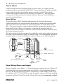
4#0#4##3URGXFW#2YHUYLHZ
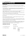
3 52'8&7# 2 9(59,(:
'(6&5,37,21
The 601 range of Frequency Inverters is designed for speed control of standard 3phase induction motors. The range covers motor power ratings from 0.37kW (1/2 hp)
to 2.2kW (3 hp).
The 601 features built in programming/operator controls and (optional) EMC
compliant RFI filters. A pullout instruction guide provides quick reference for LED
codes and terminal description.
Suitable members of the 601 range can operate from either a single phase two wire
supply of 220/240 Volts or 3 wire 380 - 460 Volts supply, 50/60Hz.
The 400V 3-phase 601 range has an internal dynamic brake switch, this allows the
user easy and convenient connection to an external resistor.
Advanced microprocessor technology provides a pulse width modulation strategy for
quiet operation.
The 601 control terminals are SELV, i.e. double insulated from power circuits to
allow easy and safe system interconnection.
The 601 is protected against overloads, excessive voltages and both phase to phase
and phase to earth short circuits via an intelligent monitoring strategy. This avoids
nuisance tripping and gives trouble free operation.
Optional internal RFI filters offer full electromagnetic compatibility (EMC) for the
majority of applications without the need for additional external components. A
comprehensive guide to EMC compliance is given in Chapter 6.
(48,30(17#6833/,('
Part Number
1) 601 Frequency Inverter
See Product Code
2) 601 Product Manual
HA464518
English (Multilingual)
Including:-
French
German
Italian
Spanish
(1*/,6+
934#0##+$79784;
3URGXFW#2YHUYLHZ#4#0#5
(8527+(50
'5,9(6
60I
E
M
7R#UHPRYH#7HUPLQDO#&RYHU#SUHVV#KHUH#DQG#SXOO#GRZQ
'%54
'%55
&ORQLQJ#FRQQHFWLRQ
+LQWHUQDO,
(8527+(50
'5,9(6
60I
/('#'LVSOD\
)XQFWLRQ
.H\V
,QVWUXFWLRQ
3XOORXW#*XLGH
E
M
4
5 6
7
8
9
:
;
&RQWURO
7HUPLQDOV
< 43
3RZHU
7HUPLQDOV
6XSSO\#3(
L1
L1
L2
4#3KDVH
6#3KDVH
L3
M1/U
L2/N
&DEOH
5HWDLQHU
M1/U
M2/V
M2/V
M3/W
M3/W
6XSSO\#3(
0RWRU#&DEOH
6FUHHQ#&ODPS
&RQWURO#:LUHV
0RWRU#3(
0RWRU#&DEOH
&RQWURO#6FUHHQ#3(
6XSSO\#&DEOH
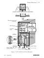
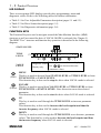
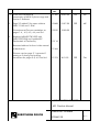
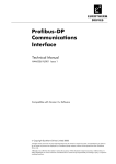
)LJXUH#414=#934#ZLWK#7HUPLQDO#&RYHU#5HPRYHG
934#0##+$79784;
(1*/,6+
4#0#6##3URGXFW#2YHUYLHZ
/('#',63/$<
Three seven segment LED displays provide drive programming, status and
diagnostic values. Refer to the following tables for further information:
• Table 5.1 for User Adjustable Parameters description (pages 5-1 and 5-2).
• Table 5.2 for Drive Status description (page 5-5).
• Table 5.3 for Diagnostics information (page 5-6).
)81&7,21#.(<6
The Function Keys are used to navigate around the Man Machine Interface (MMI)
structure as well as control the drive if LOCAL MODE is selected (See Chapter 5).
The MMI “Tree” structure and function key operation is described in the following
diagram.
STATUS LEVEL
M
TITLE
LEVEL
3ëç
ë
ê
é
3ë
M
VALUE
LEVEL
M
(Red)
E
3êûîîîûîîîûîîîû3ëç
ë
E
Diagnostic values. Current parameter values are displayed.
Use
to increase/decrease
Display only.
parameter values.
MENU
This key is used to descend from STATUS LEVEL to TITLE LEVEL or from
TITLE LEVEL to VALUE LEVEL.
This function key is also used to stop the drive when LOCAL mode is selected.
ESCAPE
E
This key is used to ascend from VALUE LEVEL to TITLE LEVEL or from
(Green)
TITLE LEVEL to STATUS LEVEL. Note this action saves the selected
parameter.
This function key is also used to start the drive when LOCAL mode is selected.
UP
This key is used to scroll through the TITLE LEVEL or increase parameter
values.
This function key is also used to increase the local setpoint and thus the
inverter frequency when LOCAL mode is selected
DOWN
This key is used to scroll through the TITLE LEVEL or to decrease parameter
values. This function key is also used to decrease the local setpoint and thus
the inverter frequency when LOCAL mode is selected.
(1*/,6+
934#0##+$79784;
3URGXFW#2YHUYLHZ#4#0#7
,16758&7,21#38//287#*8,'(
This panel gives the user sufficient information for basic operation of the product:
•
Translates the drive status information given in mnemonic form on the LED
display (eg RDY = Ready; OC = Overcurrent).
•
Decodes the titles of the parameters (P1 to P15) and the diagnostics (D1 to D3)
shown on the LED display (eg D1 = Frequency).
•
Where parameters are used to select an operating mode it decodes the numbers
assigned to each mode (eg P11 mode 1 = Coast to Stop).
•
Shows the function of each control terminal.
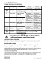
&21752/#7(50,1$/#'(6&5,37,21
7HUPLQDO
'HVFULSWLRQ
)XQFWLRQ
5DQJH
-1RWHV
4
39#UHIHUHQFH#IRU
39
39
;
DQDORJXH#,22
5
$QDORJXH#LQSXW
6SHHG#VHWSRLQW
3#0#439
4/#5/#9
6
&XUUHQW#LQSXW
6SHHG#VHWSRLQW
7#0#53P$
4/#6/#9
7
439#UHIHUHQFH
)RU#DQDORJXH#,22
439#“#8(
7
8
$QDORJXH#RXWSXW
5DPS#2XWSXW
3#0439
7/#9
9
579#VXSSO\
)RU#GLJLWDO#,22
83P$#PD[
:
'LJLWDO#LQSXW
3#9
6WRS
3#0#579
8/#9
579
5XQ
3#0#579
8/#9/#:
;
'LJLWDO#LQSXW
39
)RUZDUG
579
5HYHUVH
2U#SUHVHW#VHOHFW
3#0#579
8/#9/#:
<
'LJLWDO#LQSXW
39
6WRS
579
-RJ
2U#SUHVHW#VHOHFW
43
'LJLWDO#RXWSXW#0
347#'LJLWDO
3#0#579#RSHQ
9
6HH#&KDSWHU#8
2XWSXW#6HOHFW
FROOHFWRU#83P$#PD[
7DEOH#414
-#1RWHV
41
43#ELW#UHVROXWLRQ#3#0#439/#QR#VLJQ1
51
,QSXW#,PSHGDQFH#43NΩ;#DEVROXWH#PD[LPXP#LQSXW#YROWDJH#57#9ROWV#'&
61
,QSXW#,PSHGDQFH#583Ω;#DEVROXWH#PD[LPXP#LQSXW#YROWDJH#:1;:#9ROWV#'&1
71
$EVROXWH#PD[LPXP#RXWSXW#43P$1
81
/RJLF#ORZ#OHYHO#?#8#9ROWV>#/RJLF#KLJK#OHYHO#!#43#9ROWV/#DEVROXWH
PD[LPXP#LQSXW#YROWDJH#.63#043#9ROWV#'&1
91
8SGDWH#WLPH#43PV1
:1
6HH#SDJH#708#IRU#3UHVHW#FRQILJXUDWLRQ1
;1
,W#LV#UHFRPPHQGHG#WKDW#WKH#´392FRPPRQµ#EH#FRQQHFWHG#WR#SURWHFWLYH#
HDUWK2JURXQG#IRU#VDIHW\#UHDVRQV1##,Q#D#V\VWHP#FRPSULVLQJ#RI#PRUH#WKDQ#
RQH#FRQWUROOHU/#WKH#´392FRPPRQµ#VLJQDOV#VKRXOG#EH#FRQQHFWHG#WRJHWKHU
DQG#MRLQHG#WR#SURWHFWLYH#HDUWK2JURXQG#DW#RQH
RQH#SRLQW#RQO\1##7KLV#LV
RQH
PDQGDWRU\#WR#PHHW#WKH#(0&#VSHFLILFDWLRQ#VWDWHG1
934#0##+$79784;
(1*/,6+
4#0#8##3URGXFW#2YHUYLHZ
32:(5#7(50,1$/#'(6&5,37,21
7HUPLQDO 'HVFULSWLRQ
5HIHUHQFH
7HUPLQDO
/4
3RZHU#,QSXW
/521
3RZHU#,QSXW
/6
3RZHU#,QSXW
0428
0529
062:
3RZHU
2XWSXWV
5HIHUHQFH
7HUPLQDO
)XQFWLRQ
5DQJH
5DQJH
5339#4#3KDVH
7339#6#3KDVH
6XSSO\#SURWHFWLYH#HDUWK#+3(,1##7KLV#WHUPLQDO#PXVW#EH
FRQQHFWHG#WR#D#SURWHFWLYH#+HDUWK,#JURXQG#IRU
#IRU
SHUPDQHQW#HDUWKLQJ1
6;327939#$&
6LQJOH#DQG#WKUHH 55325739#$&
“43(#ZLWK#UHVSHFW “43(#ZLWK#UHVSHFW
SKDVH#OLYH
WR#/521
WR#/5/#/6
FRQQHFWLRQ1
6LQJOH#SKDVH
QHXWUDO#+RU#/5,/
WKUHH#SKDVH#OLYH
FRQQHFWLRQ1
7KUHH#SKDVH#OLYH
FRQQHFWLRQ1
83093+]#+,7271,55325739#$&
“43(#ZLWK#UHVSHFW
WR#/4
83093+]#+,7271,-
83093+]#+,7271,6;327939#$&
“43(#ZLWK#UHVSHFW
WR#/4/#/6
83093+]#+,7271,-
1RW#DSSOLFDEOH
6;327939#$&
“43(#ZLWK#UHVSHFW
WR#/4/#/5
83093+]#+,7271,3#WR#55325739#$& 3#WR#6;327939#$&
3#WR#573+]1
3#WR#573+]1
+'HOWD#FRQQHFWHG, +6WDU#FRQQHFWHG,
60SKDVH#VXSSO\
FRQQHFWLRQ#IRU
PRWRU1
6XSSO\#SURWHFWLYH#HDUWK#+3(,1##7KLV#WHUPLQDO#PXVW#EH
FRQQHFWHG#WR#D#SURWHFWLYH#+HDUWK,#JURXQG#IRU
IRU
SHUPDQHQW#HDUWKLQJ1
7DEOH#415
-##)RU#SURGXFWV#WKDW#DUH#ILWWHG#ZLWK#D#ILOWHU#+VHH#&KDSWHU#6#3URGXFW
:$51,1*$
###&RGH,#DQ#HDUWK#UHIHUHQFH#VXSSO\#+71,#PXVW#EH#XVHG1
&21752/#&$%/(#5(7$,1(5
This clip is used to provide guaranteed segregation of the control and power cables.
It may be rotated in either direction to allow easy installation of the control cables.
02725#&$%/(#&/$03
In order to conform with the specified generic EMC standards the motor cable must
be screened and the screen connected to both the motor frame and the motor
cable clamp. This clamp is internally connected to power terminals PE (Protective
Earth) and provides convenient 360o connection, and is used for the motor protective
earth and motor and control cable screen connections as shown in figure 1.1.
&/21,1*#&211(&725
This connector is located between the first and second top rib. It is intended to mate
with an external data module. In order for the cloning function to operate, a
compatible data module must be present (refer to Eurotherm Drives Sales
Department).
(1*/,6+
934#0##+$79784;
7HFKQLFDO#'HWDLOV##5#0#4
7 (&+1,&$/# ' (7$,/6
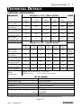
(/(&75,&$/#63(&,),&$7,21
3$5$0(7(5
0D[#6XSSO\
&XUUHQW#4SK
6XSSO\#)XVH#5DWLQJ
43#[#6;#PP
(DUWK#/HDNDJH
&XUUHQW#+)LOWHUHG,
0D[#2XWSXW
R
&XUUHQW###73 &
0D[#2XWSXW
R
&XUUHQW###83 &
+HDW#'LVVLSDWLRQ
5532573#9#“#43(##4#3KDVH#+,7271,-
81,76
316:N:2
318KS
3188N:2
31:8KS
31:8N:2
413KS
414N:2
418KS
418N:2
5KS
816
91<
<18
4513
4813
$PSV#$&
+506,
43
43
43
53
53
$PSV
:18
:18
:18
:18
:18
P$
515
613
713
818
:13
$PSV#$&
515
515
613
718
718
$PSV#$&
:3
:DWWV
55
65
75
88
6;32793#9#“#43(##6#3KDVH#+,7271,-
316:N:2 3188N:2 31:8N:2 414N:2
318KS
31:8KS
413KS
418KS
418N:2
5KS
0D[#6XSSO\
514
51:
617
715
815
&XUUHQW#6SK
6XSSO\#)XVH#5DWLQJ
43
43
43
43
43
43#[#6;#PP
(DUWK#/HDNDJH
43
43
43
43
43
&XUUHQW#+)LOWHUHG,
0D[#2XWSXW
418
513
518
618
718
R
&XUUHQW###73 &
0D[#2XWSXW
418
513
513
618
618
R
&XUUHQW###83 &
+HDW#'LVVLSDWLRQ
46
4;
56
64
74
'\QDPLF#%UDNLQJ '%5#0LQLPXP#5HVLVWDQFH ;5#2KPV
6ZLWFK
'%5#'XW\#&\FOH
433#(#+FRQWLQXRXV#UDWLQJ,
6SHFLILFDWLRQ
$//#934#5$1*(
515N:2
6KS
91<
$PSV#$&
+506,
43
$PSV
43
P$
818
$PSV#$&
813
$PSV#$&
87
:DWWV
6XSSO\#)UHTXHQF\=
3RZHU#)DFWRU#+ODJ,=
2XWSXW#)UHTXHQF\=
2YHUORDG=
6XSSO\#6KRUW#&LUFXLW#5DWLQJ
)XVH#5DWLQJ#DQG#3DUW#1XPEHU=
83293+]#±43(
31<#+##83293+],
3#0#573#+]
483(#IRU#63#VHFRQGV
8333#$PSV
43$ &+763347
53$ &+763357
)XVH#+ROGHU#43#[#6;##PP#3DUW#1XPEHU= &3384935
* Products fitted with a filter must only be used on earth referenced supplies (TN).
7DEOH#514
934#0##+$79784;#
(1*/,6+
5#0#5##7HFKQLFDO#'HWDLOV
(19,5210(17$/#63(&,),&$7,21
2SHUDWLQJ#7HPS
3#0#73°&#+VHH#7DEOH#514#IRU#FXUUHQW#UDWLQJ#DW#83R&,
6WRUDJH#7HPS
058#0#.88°&
6KLSSLQJ#7HPS
058#0#.:3°&
&OLPDWLF#&RQGLWLRQV
&ODVV#6.6/#DV#GHILQHG#E\#SU(1834:;#+4<<8,
(QFORVXUH#5DWLQJ
,353#+8/#2SHQ#7\SH,#VXLWDEOH#IRU#FXELFOH#PRXQW#RQO\1
$OWLWXGH
$ERYH#4333P#GHUDWH#4(#SHU#433P
+XPLGLW\
0D[1#;8(#5HODWLYH#+XPLGLW\#DW#73°&
(0& &RQGXFWHG
(PLVVLRQV
5339#6LQJOH#3KDVH
7339#603KDVH
414N:#)#418N: 316:23188231:8N:
+$OO,
48P#0RWRU
&DEOH#0D[LPXP
58P#0RWRU#&DEOH
0D[LPXP
58P#0RWRU
&DEOH#0D[LPXP
(1833;404+4<<5,
(1833;40
5+4<<7,
,QWHUQDO#ILOWHU
5DGLDWHG
(PLVVLRQV
(1833;404+4<<5,#>DOO#PRGHOV@#ZKHQ#PRXQWHG#LQVLGH#D
FXELFOH#SURYLGLQJ#48G%#HOHFWURPDJQHWLF#UDGLDWLRQ
DWWHQXDWLRQ#EHWZHHQ#63#DQG#4330+]/#VFUHHQHG#FRQWURO
DQG#PRWRU#FDEOHV#RXWVLGH#RI#FXELFOH1##&RQWURO#39#PXVW#EH
FRQQHFWHG#WR#SURWHFWLYH#HDUWK2JURXQG1
,PPXQLW\
SU(1833;505#+4<<5,/#(1833;504#+4<<5,
6DIHW\
(1834:;+4<<;,/#9'(#3493#+4<<7,/
,QVWDOODWLRQ22YHUYROWDJH#&DWHJRU\#6/#3ROOXWLRQ#'HJUHH#5
ZKHQ#ILWWHG#LQVLGH#D#VXLWDEOH#FRQWURO#FXELFOH1
7DEOH#515
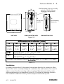
0(&+$1,&$/#63(&,),&$7,21
The enclosure has IP20 ingress protection. A suitable control cubicle must be used
where necessary to comply with local wall mount requirements. To maintain
compliance with the European Electrical Safety Standard VDE0160(1994) /
EN50178(1998) the 601 should be mounted inside a suitable control cubicle
requiring a tool for opening.
0RXQWLQJ
The 601 must be mounted vertically on a solid flat non-inflammable vertical
surface either panel mounted or on a rail complying with EN50022 (35mm DIN).
The unique dual action clip allows the 601 to be easily panel or DIN rail mounted.
(1*/,6+
934#0##+$79784;
7HFKQLFDO#'HWDLOV##5#0#6
Wall mounting clip can be easily
pushed to allow different
mounting configurations.
W
H2
H
H1
H3
Fixing hole
centres
Din Mounting
dimension
W1
D
SIDE VIEW
PANEL MOUNTING VIEW
DIN MOUNTING VIEW
)LJXUH#514
$OO#'LPHQVLRQV#DUH#LQ#PLOOLPHWUHV#+#LQFKHV#,
+
+4
+5
+6
:
:4
'
4;613
4;;13
53813
48413
:513
6913
4:813
+:153µ,
+:17µ,
+;13:µ,
+81<7µ,
+51;6µ,
+4174µ,
+91;<µ,
)L[LQJV
0RXQWLQJ#+ROHV#818#PP1##8VH#08#IL[LQJV1
:HLJKW
55325739#5DQJH#414#NJ#+518#OEV,1
6;327939#5DQJH#418#NJ#+616#OEV,1
Maintain a minimum clearance for ventilation of 100 mm ( 4 in ) above
and below.
7DEOH#516
9HQWLODWLRQ
In normal operation the 601 dissipates heat and must therefore be mounted to allow
the free flow of air vertically through the ventilation slots and heatsink. Care must be
taken to ensure that the mounting surface is cool and that heat generated by other
adjacent equipment is not transmitted to the 601. Provided the minimum clearance
for ventilation is adhered to these products maybe mounted side-by-side.
934#0##+$79784;#
(1*/,6+
6#0#4##3URGXFW#&RGH
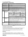
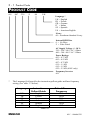
352'8&7#&2'(
601
/007
/230
/F
/00
/UK
Language *
UK = English
FR = French
GR = German
IT = Italian
SP = Spanish
US = American English
Livery
00 = Eurotherm Standard Livery
Internal RFI Filter
0 = No Filter
F = Filter Fitted
AC Supply Voltage +/- 10 %
230 = 220 / 240 V AC 1-Phase
400 = 380 / 460 V AC 3-Phase
Power Ratings
003 = 0.37 kW
005 = 0.55 kW
007 = 0.75 kW
011 = 1.1 kW
015 = 1.5 kW
022 = 2.2 kW (400V only)
Frequency Inverter
601
*
The Language field specifies the instruction pullout guide and base frequency
setting (see table 3-1 below).
/DQJXDJH
UK
FR
GR
IT
SP
US
(1*/,6+
,QVWUXFWLRQ
3XOORXW#*XLGH
English
French
German
Italian
Spanish
English
7DEOH#604
'HIDXOW#%DVH
)UHTXHQF\
50 Hz
50 Hz
50 Hz
50Hz
50 Hz
60 Hz
934#0##+$79784;
(OHFWULFDO#,QVWDOODWLRQ##7#0#4
(/(&75,&$/#,167$//$7,21
Read the Safety Information at the front of the manual before proceeding.
:,5,1*#*8,'(/,1(6#)25#(0&
The 601 series has been designed to comply with the European Community Directive
89/336/EEC on EMC. In particular the 601 meets the given generic emission and
immunity standards specified in table 2.2 when suitably cubicle mounted and when
the internal RFI filter option is fitted.
The following wiring guidelines must be followed to prevent interference with other
electrical equipment.
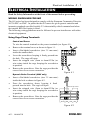
8VLQJ#&DJH#&ODPS#7HUPLQDOV
&RQWURO#DQG#3RZHU
To wire the control terminals or the power terminals (see figure 4-1):
•
•
•
•
•
Remove the terminal cover as shown in figure 1.1.
Insert a flat-bladed screwdriver (size 3.5 mm max.)
inside the smallest hole.
Lever the screwdriver keeping it firmly pressed into
the hole. The cage will open.
Insert the stripped wire (5mm to 6mm/0.22in.) or
wire crimp inside the cage keeping the screwdriver
in position.
Remove the screwdriver. Note the cage provides the
correct force for a secure connection.
)LJXUH#714
'\QDPLF#%UDNH#7HUPLQDO#+7339#RQO\,
•
•
•
•
Insert a flat-bladed screwdriver (size 3.5 mm max.)
inside the hole as shown in figure 4.2.
Press the screwdriver down, keeping it firml
pressed into the hole. The cage will open.
Insert the stripped wire (5mm to 6mm/0.22in.) or
wire crimp inside the cage keeping the screwdriver
in position.
Remove the screwdriver. Note the cage provides the
correct force for a secure connection.
5HDU#RI#WRS#FRYHU
DBR1
DBR2
)LJXUH#715
934#0##+$79784;#
(1*/,6+
7#0#5#(OHFWULFDO#,QVWDOODWLRQ
&RQWURO#&DEOHV
Control wiring should be segregated from all power wiring. To comply with the
radiated emissions requirements of EN50081-1 the product must be inside a suitable
control cubicle and the control cables must be screened outside of the cubicle.
Connect the screen to earth at the 601 end only (see figure 4.3). Note the cubicle
must provide 15dB attenuation to radiated emissions between 30 and 100MHz to
meet the residential limits.
0RWRU#:LULQJ
To meet the generic EMC Standards and minimise the electrical interference,
connections between the Inverter and the motor must be made using screened cable.
The screens must be connected to the motor frame and to the motor cable clamp
(PE). The motor protective earth conductor should be connected at the drive end to
the motor PE point. Where it is necessary to interrupt the screened cable for
connection to circuit breakers or other devices, the screens should be connected over
the shortest distance possible.
The motor cables should be segregated from all other wiring and should not be run in
the same conduit/trunking as supply or control wiring. The recommended method for
terminating the screen on screened motor cables is shown on the following figure.
6XSSO\#3(
/4
/5
/6
M1/U
/4
4#3KDVH
6#3KDVH
L2/N
M1/U
M2/V
M2/V
M3/W
M3/W
6XSSO\#3(
&RQWURO#VFUHHQ#3(
&RQWURO#FDEOH#VFUHHQ
0RWRU#3(
0RWRU#&DEOH#6FUHHQ#&ODPS
0RWRU
&DEOH
&RQWURO
&DEOH
6XSSO\
&DEOH
)LJXUH#716
3RZHU#:LULQJ#+0RWRU#DQG#6XSSO\,
Remove terminal cover (figure 1.1). For typical power connections refer to figure 4.3.
Eurotherm Drives do not recommend the use of RCDs. If local regulations dictate
their use, RCDs which function with DC components of earth leakage current (Type
B as defined in IEC 755/A2) RCDs are only acceptable, otherwise all loads requiring
protection with the RCD will be at risk. Filtered 601s must be permanently earthed
(1*/,6+
934#0##+$79784;
(OHFWULFDO#,QVWDOODWLRQ##7#0#6
by using two independent protective earth incoming supply conductors (figure 4.3).
This is due to the high earth leakage current when using filters.
The incoming mains supply should be protected by a suitable fuse or circuit breaker,
as shown in table 2.1.
Power cables should be
specified to this table:-
Current Rating
Cable size
Cable size
< = 8 Amps
1 mm2
16 AWG
< = 10 Amps
1.5 mm2
14 AWG
< = 15 Amps
2.5 mm2
12 AWG
7DEOH#714
When the wires are fully inserted into the terminal to maintain IP20 protection they
need to be stripped to 5 - 6 mm (0.22 in).
&RQWURO#:LULQJ
All control and signal terminals are SELV, i.e., protected by double/reinforced
insulation. Ensure all wiring rated for highest system voltage. Control wiring of
between 0.08 mm2 (28 AWG) - 2.5 mm2 (14 AWG) can be used.
Remove the terminal cover (see figure 1.1). Rotate the Control Cable Retainer, route
the control cables in the right hand compartment and wire to the control terminals.
Rotate the Control Cable Retainer to hold the cables in the designated compartment.
Figure 4.4 shows a typical control connections required for operation as a simple
speed controller.
* It is recommended that the
“0V/common” be connected to
protective earth/ground for safety
reasons. In a system comprising
of more than one controller, the
“0V/common” signals should be
connected together and joined to
protective earth/ground at one
point only. This is mandatory to
meet the EMC specification
stated.
4
5
6
7
8
9
:
;
<
43
-
6SHHG
43N 6HWSRLQW
5XQ
-RJ
'LUHFWLRQ
+HDOWK#5HOD\
579#83P$#PD[1
)LJXUH#717
934#0##+$79784;#
(1*/,6+
7#0#7#(OHFWULFDO#,QVWDOODWLRQ
The terminal used to control the speed of the motor depends on the setting of
Parameter P13 Setpoint Select as shown in Table 4.2 below:
3DUDPHWHU
&RQWURO
&RQWURO
46
7HUPLQDO#; 7HUPLQDO#<
0
1
2
6HWSRLQW#6RXUFH
0V
0V
Control Terminal 2 (0-10V) - forward
0V
24V
Jog Speed (set by Parameter P8) - forward
24V
0V
Control Terminal 2 (0-10V) - reverse
24V
24V
Jog Speed (set by Parameter P8)- reverse
0V
0V
Control Terminal 3 (4-20mA) - forward
0V
24V
Jog Speed (set by Parameter P8) - forward
24V
0V
Control Terminal 3 (4-20mA) - reverse
24V
24V
Jog Speed (set by Parameter P8)- reverse
0V
0V
Preset Speed 1 (set by Parameter P1)
24V
0V
Preset Speed 2 (set by Parameter P8)
0V
24V
Preset Speed 3 (set by Parameter P9)
24V
24V
Preset Speed 4 (set by Parameter P2)
7DEOH#715
5(48,5(0(176#)25#8/#&203/,$1&(
0RWRU#%DVH#)UHTXHQF\
The motor base frequency rating is 240Hz maximum
)LHOG#*URXQGLQJ#7HUPLQDOV
The International Grounding Symbol
(IEC Publication 417, Symbol 5019) is used
to designate the field grounding terminals. Refer also to page 1-5, “Power Terminal
Description”
6KRUW#&LUFXLW#5DWLQJ
All models are suitable for use on a circuit capable of delivering not more than 5000
RMS Symmetrical Amperes, 240/460V maximum.
)LHOG#:LULQJ#7HUPLQDO#0DUNLQJV
For proper connections that are to be made to each terminal, refer to page 1-4,
“Control Terminal Description” and page 1-5, “Power Terminal Description”.
)LHOG#:LULQJ#7HPSHUDWXUH#5DWLQJ
Use 60°C Copper Conductors only.
(1*/,6+
934#0##+$79784;
(OHFWULFDO#,QVWDOODWLRQ##7#0#8
7HUPLQDO#7LJKWHQLQJ#7RUTXH
Terminals using automatic cage clamps are provided. Tightening torque is not
applicable.
,QWHUQDO#2YHUORDG#3URWHFWLRQ
These devices provide Class 10 motor overload protection. The maximum internal
overload protection level (current limit) is 150% for 30 seconds. Refer page 5-1 for
user current limit adjustment information.
An external motor overload protective device must be provided by the installer
where the motor used has a full-load ampere rating of less than 50% of the drive
output rating.
6ROLG#6WDWH#6KRUW#&LUFXLW#3URWHFWLRQ
These devices are provided with solid state short circuit (output) protection. Branch
circuit protection should be provided as specified in the National Electrical Code,
NEC/NFPA-70.
3RZHU#:LULQJ#7HUPLQDOV
The wiring terminals accept a maximum conductor size of No. 12 AWG (3.3mm2).
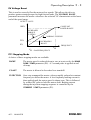
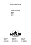
'<1$0,&#%5$.,1*#63(&,),&$7,21
During deceleration, or with an overhauling load, the motor acts as a generator.
Energy flows back from the motor into the DC link capacitors within the Frequency
Inverter. This causes the DC link voltage to rise. If the DC link voltage exceeds
810V then the Frequency Inverter will trip to protect the capacitors and the Inverter
power devices. The amount of energy that can be absorbed in the capacitors is
relatively small; typically more than 20 % braking torque will cause the Frequency
Inverter to trip on overvoltage. Dynamic braking increases the braking capability of
the Frequency Inverter by dissipating the excess energy in a high power resistor
connected across the DC link. See Figure 4.5 for Dynamic Brake Switch
specification.
'%54
EXTERNAL
RESISTOR
NETWORK
+
'%55
GATE
DRIVE
CIRCUIT
When the DC link voltage rises
above 750 V, the brake unit switches
the external resistor network across
the DC link. The brake unit switches
off again when the DC link voltage
falls below the threshold level. The
amount of energy produced by the
motor during regeneration depends
upon the RAMP DOWN TIME
parameter and the inertia of the load.
)LJXUH#718#'\QDPLF#%UDNLQJ#&LUFXLW
934#0##+$79784;#
(1*/,6+
7#0#9#(OHFWULFDO#,QVWDOODWLRQ
NOTE: THE DYNAMIC BRAKING CIRCUIT IS DESIGNED TO COPE
WITH SHORT TERM STOPPING OR BRAKING ONLY.
IT IS NOT RATED FOR A CONTINUOUSLY OVERHAULING LOAD.
All 601 units are supplied without braking resistors. The following paragraphs
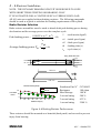
should be used as a guide to calculate the braking requirements of the system.
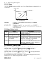
%UDNH#5HVLVWRU#6HOHFWLRQ
Brake resistor assemblies must be rated to absorb both peak braking power during
deceleration and the average power over the complete cycle.
Peak braking power =
0.0055J x (n 12- n 2 2 )
t
J
(W)
- total inertia (kgm2)
n1 - initial speed (rpm)
b
n2 - final speed (rpm)
p pk
tb - braking time (s)
Average braking power Pav = t x t b
c
tc - cycle time (s)
flying leads 500 mm
10 mm
45#PP
152 mm
4.3mm
22 mm
12 mm
10 mm
458#PP
41 mm
498#PP
Resistor Derating Graph
chassis mounted
10
% of Rated
Power
free air
50
0
0
25
50
75
10
12
Ambient Temp (C)
15
17
20
Eurotherm Part No
Resistance
Max Wattage
5 second rating
3 second rating
1 second rating
CZ389853
100 ohms
100 W
500 %
833 %
2500 %
)LJXUH#719#%UDNLQJ#5HVLVWRU#3HUIRUPDQFH
These resistors should be mounted on a heatsink (back panel) and covered to prevent
injury from burning.
(1*/,6+
934#0##+$79784;
2SHUDWLQJ#'HVFULSWLRQ##8#0#4
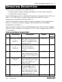
23(5$7,1*#'(6&5,37,21
The 601 can be controlled in two different ways:
1. Remote Mode using the analogue and digital i/o on the control terminals.
2. Local Mode using the keypad.
On the LED display, the User Adjustable Parameters are identified as P1 to P15 (see
table 5.1), the Drive Status is shown using mnemonics (table 5.2), and the
Diagnostics are identified as D1-D3 (table 5.3).
The 601 has parameters factory defaults which are adequate for most applications.
However, it may be necessary to change some Parameters to suit individual
installations (see Chapter 1).
Parameters Base Frequency (P7), and Bit Parameters (P11-P15) cannot be changed
when the motor is running. No Parameter (P1-P15) can be changed when the 601 is
in Local Mode.
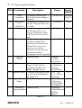
86(5#$'-867$%/(#3$5$0(7(56
7LWOH
3ë
3ê
3é
3è
3ç
3æ
7UDQVODWLRQ
'HVFULSWLRQ
0LQLPXP#6SHHG 7KH#IUHTXHQF\#DW#ZKLFK#WKH
934#ZLOO#UXQ#ZKHQ#]HUR
RU
VHWSRLQW#LV#DSSOLHG#XQOHVV
+3UHVHW#4,
FODPSHG#E\#35
0D[LPXP#6SHHG 7KH#IUHTXHQF\#DW#ZKLFK#WKH
934#ZLOO#UXQ#ZKHQ
RU
0D[LPXP#6HWSRLQW#LV
+3UHVHW#7,
DSSOLHG
5DPS#8S#7LPH 7KH#WLPH#WDNHQ#IRU#WKH#934
RXWSXW#IUHTXHQF\#WR#UDPS
XS#IURP#]HUR#WR#0D[LPXP
6SHHG
5DPS#'RZQ
7KH#WLPH#WDNHQ#IRU#WKH#934
7LPH
RXWSXW#IUHTXHQF\#WR#UDPS
GRZQ#IURP#0D[LPXP
6SHHG#WR#]HUR
&XUUHQW#/LPLW /LPLWV#WKH#RXWSXW#FXUUHQW#WR
WKH#SHUFHQWDJH#YDOXH
VSHFLILHG1##7KH#934#ZLOO
DXWRPDWLFDOO\#UHGXFH#WKH
RXWSXW#IUHTXHQF\#LQ#RUGHU
WR#VWD\#ZLWKLQ#WKLV#OLPLW
9ROWDJH#%RRVW +'HWDLOHG#RYHU,
934#0##+$79784;#
5DQJH
30573#+]
)DFWRU\
'HIDXOW
3+]
30573#+]
83293+]
3140<<<V
43V
3140<<<V
43V
83#0#483#(
433#(
3#0#58#(
8#(
(1*/,6+
8#0#5##2SHUDWLQJ#'HVFULSWLRQ
7LWOH 7UDQVODWLRQ
3å
'HVFULSWLRQ
5DQJH
)DFWRU\
'HIDXOW
580573#+]
83293+]
7KH#RXWSXW#IUHTXHQF\#DW
+VHH#604,
ZKLFK#PD[LPXP#YROWDJH#LV
UHDFKHG1
Sä
30573#+]
43+]
-RJ#6SHHG 7KH#VSHHG#DW#ZKLFK#WKH#934
ZLOO#UXQ#LI#&RQWURO#7HUPLQDO
RU
<#LV#KLJK
+3UHVHW#5,
3ã 3UHVHW#6SHHG#6 7KH#VSHHG#DW#ZKLFK#WKH#934
30573#+]
58+]
ZLOO#UXQ#ZKHQ#346# #5/
&RQWURO#7HUPLQDO#;#LV#ORZ
DQG#&RQWURO#7HUPLQDO#<#LV
KLJK
3ëì
3#0#<<<
3
3DVVZRUG
$#SDVVZRUG#PD\#EH#VHW#WR
SURKLELW#XQDXWKRULVHG
DGMXVWPHQW#RI#3DUDPHWHUV1
:KHQ#343#LV#VHW#WR#QRQ0
]HUR#WKH#XVHU#ZLOO#EH
UHTXLUHG#WR#PDWFK#WKH#ODVW
VDYHG#YDOXH#EHIRUH
3DUDPHWHUV#FDQ#EH#DGMXVWHG
3ëë
3
6WRSSLQJ
+'HWDLOHG#RYHU,
3 5DPS
0RGH
4 &RDVW
5 ,QMHFWLRQ
3ëê 92)#6KDSH +'HWDLOHG#RYHU,
3
3 /LQHDU
4 4XDGUDWLF
5DQJH#5#DQG#6#RI#WKLV
5 /LQHDU
SDUDPHWHU#GLVDEOHV#WKH
6 4XDGUDWLF
Stall Trip#IXQFWLRQ1
3ëé 6HWSRLQW#6HOHFW $#PHWKRG#RI#SURJUDPPLQJ 3 3#0#439
3
WKH#VRXUFH#RI#WKH#6HWSRLQW#0 4 7#0#53P$
5 3UHVHWV
VHH#7DEOH#715
3ëè 'LJLWDO#2XWSXW +'HWDLOHG#RYHU,
3
3 +HDOWK\
6HOHFW
4 5XQQLQJ
5 0LQ#6SHHG
6 $W#6SHHG
3ëç 3DUDPHWHU +'HWDLOHG#RYHU,
3
3 1RUPDO
&RS\LQJ#0RGH
4 5HDG#([WHUQDO
5 :ULWH
([WHUQDO
%DVH
)UHTXHQF\
7DEOH#814
(1*/,6+
934#0##+$79784;
2SHUDWLQJ#'HVFULSWLRQ##8#0#6
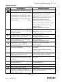
39#9ROWDJH#%RRVW
This is used to correctly flux the motor at low speeds. This allows the drive to
produce greater starting torque for high friction loads. The VOLTAGE BOOST
parameter increases the motor volts above the selected V/F characteristic at the lower
end of the speed range.
OUTPUT VOLTS
CONSTANT
POWER RANGE
100%
INCREASED
TORQUE
FLUXING
NORMAL FLUXING
25%
INCREASING
BOOST
0%
fB
fB
FREQUENCY
= BASE FREQUENCY
344#6WRSSLQJ#0RGH
A choice of three stopping modes are available:
RAMP
The motor speed is reduced down to zero at a rate set by the RAMP
DOWN TIME parameter (P4). A 2 second pulse is applied at end
of ramp.
COAST
The motor is allowed to freewheel to a standstill.
INJECTION
On a stop command the motor volts are rapidly reduced at constant
frequency to deflux the motor. A low frequency braking current is
then applied until the motor speed is almost zero. This is followed
by a timed DC pulse to hold the motor shaft. Braking current
during the injection stopping sequence is controlled by the
CURRENT LIMIT parameter (P5).
934#0##+$79784;#
(1*/,6+
8#0#7##2SHUDWLQJ#'HVFULSWLRQ
345#92)#6KDSH
The V/F SHAPE parameter enables one of two voltage/frequency characteristics to
be selected;
OUTPUT VOLTS
CONSTANT
POWER RANGE
100%
LINEAR
QUADRATIC LAW
FREQUENCY
f B = BASE FREQUENCY
fB
LINEAR
This gives a constant flux characteristic up to the BASE
FREQUENCY.
QUADRATIC
This gives a quadratic flux characteristic up to the BASE
FREQUENCY. This matches the load requirement for fan and most
pump applications.
347#'LJLWDO#2XWSXW#6HOHFW
9DOXH
1DPH
3
+HDOWK\28QKHDOWK\
4
5XQQLQJ21RW#UXQQLQJ
5
$W#PLQ#VSHHG2DERYH
PLQ#VSHHG
6
$W#VSHHG2QRW#DW#VSHHG
'HVFULSWLRQ
&RQWURO#WHUPLQDO#43#ZLOO#EH#KHOG#ORZ#ZKHQ
QR#WULSV#DUH#SUHVHQW1
&RQWURO#WHUPLQDO#43#ZLOO#EH#KHOG#ORZ#ZKHQ
WKH#PRWRU#LV#UXQQLQJ1
&RQWURO#WHUPLQDO#43#ZLOO#EH#KHOG#ORZ#ZKHQ
WKH#RXWSXW#IUHTXHQF\#LV#DW2RU#EHORZ
PLQLPXP#VSHHG#VHWWLQJ#341
&RQWURO#WHUPLQDO#43#ZLOO#EH#KHOG#ORZ#ZKHQ
WKH#RXWSXW#IUHTXHQF\#LV#ZLWKLQ##+313348#[
0D[#6SHHG#+35,,#RI#VHWSRLQW1
348#3DUDPHWHU#&RS\LQJ#0RGH
This parameter will always display zero when the value level is first entered.
Selecting Mode 1 (by pressing
once then pressing M will copy a
configuration to the 601 from a compatible external device.
Selecting Mode 2 (by pressing
twice then pressing M will copy the current
601 configuration to a compatible external device.
If copying and verifying the configuration is successful the display will revert to 0,
otherwise an “Err” status message will be displayed.
(1*/,6+
934#0##+$79784;
2SHUDWLQJ#'HVFULSWLRQ##8#0#8
'5,9(#67$786
7LWOH
'HVFULSWLRQ
3RVVLEOH#&DXVH
5($'<2+($/7+<#+1R#$ODUPV#3UHVHQW,1
2F
29(5&855(171
93423362563#0#934233:2563
93423362733#0#93423482733
93423442563#0#93423482563
93423552733
55$
55$
77$
63$
Ramp Up 7LPH##WRR#VKRUW#IRU#LQHUWLD#RI
ORDG#DQG2RU#SRZHU#UDWLQJ#RI#9341
Ramp Down 7LPH#WRR#VKRUW#IRU#LQHUWLD#RI
ORDG#DQG2RU#SRZHU#UDWLQJ#RI#9341
$SSOLFDWLRQ#RI#VKRFN#RYHUORDG1
6KRUW#FLUFXLW#EHWZHHQ#PRWRU#SKDVHV1
6KRUW#FLUFXLW#IURP#PRWRU#SKDVH#WR#HDUWK1
0RWRU#FDEOHV#WRR#ORQJ#RU#WRR#PDQ\
SDUDOOHO#PRWRUV1
Voltage Boost VHW#WRR#KLJK1
ûRX
29(592/7$*(1##'&#EXV#YROWDJH
H[FHHGHG#743#9#GF1#+;43#9#GF#IRU#733
9#60SKDVH#YHUVLRQ,1
û
,#[#W#29(5/2$'1##&XPXODWLYH#RYHUORDG /RDG#LV#WRR#KLJK1
DW#483(#FXUUHQW#IRU#63#VHFRQGV1
Voltage Boost VHW#WRR#KLJK1
û
V
67$//1##'ULYH#ZDV#LQ#FXUUHQW#OLPLW#IRU
PRUH#WKDQ#533#VHFRQGV1
/RDG#LV#WRR#KLJK1
Voltage Boost VHW#WRR#KLJK1
û
R
29(57(03(5$785(1##+HDWVLQN
R
WHPSHUDWXUH#H[FHHGHG#433 #&1
$PELHQW#WHPSHUDWXUH#WRR#KLJK1
3RRU#YHQWLODWLRQ1
6$9,1*#(55251#3UREOHP#VDYLQJ
3DUDPHWHUV#WR#((35201
([WHUQDO#GHYLFH#SUHVHQW#RU#QRW
FRPSDWLEOH1
(
7KH#VXSSO\#YROWDJH#LV#WRR#KLJK1
Ramp Down 7LPH##WRR#VKRUW#IRU#ORDG
LQHUWLD2SRZHU#UDWLQJ1
$#SRZHU#VXSSO\##SUREOHP#RFFXUUHG
GXULQJ#VDYLQJ1
ûFO
&855(17#/223#/2661##7#0#53#P$
VHWSRLQW#FXUUHQW#OHVV#WKDQ#4P$1
$#FXUUHQW#RI#OHVV#WKDQ#4P$#LV#SUHVHQW
ZKHQ#7053P$#VHWSRLQW#LV#VHOHFWHG1
SDV
3$66:25'1##&XUUHQW#SDVVZRUG#PXVW
EH#HQWHUHG#EHIRUH#WKLV#SDUDPHWHU#PD\
EH#DOWHUHG1
(QWHU#SDVVZRUG#WR#FKDQJH#WKH
SDUDPHWHU1
3$66:25'#,1&255(&71##:URQJ
SDVVZRUG#HQWHUHG1
&XUUHQW#SDVVZRUG#GRHV#QRW#PDWFK
HQWHUHG#SDVVZRUG1
/2&$/1##/RFDO#PRGH#VHOHFWHG
'HWDLOHG#RYHU1
6
5(6(71##)DFWRU\#GHIDXOW#UHVHW
'HWDLOHG#RYHU1
XX
81'(592/7$*(#%XV#YROWDJH#KDV
IDOOHQ#EHORZ#533#9ROWV#GF#+7339#GF#IRU
7339#60SKDVH#YHUVLRQ,1
6XSSO\#YROWDJH#KDV#EHHQ#LQWHUUXSWHG#RU
JRQH#EHORZ#VSHFLILFDWLRQ1
ïïï
ORF
7DEOH#815
934#0##+$79784;#
(1*/,6+
8#0#9##2SHUDWLQJ#'HVFULSWLRQ
When a trip occurs a status message is flashed (de-coded by the above table 5.2).
When the RUN command is removed the status message will stop flashing if the
alarm has cleared. This will bring low control terminal 10 if Healthy/Unhealthy has
been selected parameter P14 = 0. This places the product into a state where the RUN
command can be re-applied and if the alarm does not reoccur the product will run
normally.
5HVHW#WR#)DFWRU\#'HIDXOW#9DOXHV
All parameters can be returned to factory default settings by powering up the 601
while both
keys are pressed simultaneously.
',$*1267,&6
7LWOH
ë
'HVFULSWLRQ
FREQUENCY. This diagnostic gives the current output frequency in
Hz.
ê
SET POINT. This diagnostic gives the set point frequency in Hz.
é
LOAD. This diagnostic gives current load value as % of 601 rating.
7DEOH#816
6(/(&7,1*#$1'#23(5$7,1*#/2&$/#02'(
simultaneously from the status level and
To select Local mode press
stopped. The display will begin to spell OìFðûWhen all three letters are displayed
and the word ORF is flashing release the
keys or the display will revert
back to Ud\ (remote mode). The display now shows the local setpoint which can be
increased using the
or decreased using the
key. The E (green) key can
be used to start the 601 and the M (red) key can be used to stop the 601. While in
the stopped state pressing the M key will show the current direction. This
direction may be changed by holding down the M key while simultaneously
pressing either the
key for )
(forward) or the
key for (8 (reverse).
To clear a fault, press M .
and
simultaneously. For safety, the
To return to Ud\û(remote mode) press
drive will not return to the remote mode if this will cause the drive to start. In this
event the display will flash. Check RUN and JOG inputs are low.
(1*/,6+
934#0##+$79784;
(XURWKHUP#(0&#DQG#WKH#¶&(·#0DUN###9#0#4
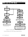
(0&#$1'#7+(#¶&(·#0$5.
START
IS E.D. MODULE
RELEVANT APPARATUS
WITH INTRINSIC FUNCTION
TO END USER (CEMEP
VALIDITY FIELD 1)
NO
CEMEP VALIDITY FIELDS
2, 3 AND 4
YES
OPTIONAL E.D. FILTERS
AVAILABLE TO ASSIST USERS
IN CONFORMANCE WITH THE
EMC DIRECTIVE
WILL THE E.D. PRODUCT
BE INSTALLED
ACCORDING TO THE
INSTALLATION
GUIDELINES
NO
EMC CHARACTERISTICS
STATED IN MANUAL
YES
FIT THE SPECIFIED
E.D. EMC FILTER
THE E.D. EC DECLARATION OF
CONFORMITY FOR EMC IS VALID
FOR THE SPECIFIED ED MODULE
EMC INSTALLATION GUIDELINES
STATED IN MANUAL
THE E.D. MANUFACTURERS DECLARATION
FOR EMC IS VALID FOR THE SPECIFIED
MODULE WHEN INSTALLED CORRECTLY
EMC 'CE' MARK CAN BE APPLIED TO E.D.
A GLOBAL EMC SOLUTION
MODULE TO GENERIC EMC STANDARDS:
MAYBE ADVANTAGEOUS
EN50081-1(1992) AND/OR EN50081-2(1994), AND
EN50082-1(1992) (AND prEN50082-2(1992)).
E.D. = EUROTHERM DRIVES LIMITED
NO EMC 'CE'MARK APPLIED TO E.D MODULE
RELEVANT APPARATUS
MANUFACTURER/SUPPLIER/INSTALLERS
RESPONSIBILITY TO CONFORM WITH EMC DIRECTIVE.
E.D. EMC CHARACTERISTICS AND MANUFACTURERS
DECLARATION MAY BE USED AS A BASIS IN THE
OVERALL PRODCT JUSTIFICATION
)LJXUH#914##(XURWKHUP#(0&#¶&(·#0DUN#9DOLGLW\#&KDUW
For more information refer to EMC Application Manual HA388879
934#0##+$79784;#,VVXH#5#
(1*/,6+
:#0#4##0DLQWHQDQFH#)#5HSDLU
0$,17(1$1&(#$1'#5(3$,5
0$,17(1$1&(
Routine maintenance of the 601 comprises a periodic inspection to check for a buildup of any dust, or other obstructions, that may affect the ventilation of the unit.
Obstructions should be removed and any dust must be cleared using dry air.
5(3$,5
The 601 contains no user serviceable component and MUST NOT BE REPAIRED by the
user.
If repair is necessary, return the unit to Eurotherm Drives.
5(7851('#0$7(5,$/
The following procedures are recommended in the event of a fault which necessitates
return of an item to Eurotherm Drives.
You will require the following information:
1.
The model and serial number of the faulty item.
2.
Details of the fault.
Contact your nearest Eurotherm Drives Service Centre to arrange return of the item.
Refer to the list of Eurotherm Drives Service Centres at the end of this Guide.
On contacting your local Eurotherm Drives Service Centre you will be given a
Returned Material Authorisation code which must be used as a reference on all
paperwork returned with the equipment.
Pack and despatch the item.
(1*/,6+
934#0##+$79784;#,VVXH#5
(8527+(50
9,7(66(
9$5,$%/(
934
0DQXHO#GX#3URGXLW
#&RS\ULJKW#(XURWKHUP#'ULYHV#/LPLWHG#4<<<
All rights strictly reserved. No part of this document may be stored in a retrieval system, or
transmitted
in any form or by any means to persons not employed by a Eurotherm group company without
written permission from Eurotherm Drives Ltd.
Although every effort has been taken to ensure the accuracy of this document it may be necessary,
without notice, to make amendments or correct omissions. Eurotherm Drives cannot accept
responsibility for damage, injury, or expenses resulting therefrom.
3ULQWHG#LQ#(QJODQG
+$79784;
,VVXH
6
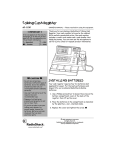
,66
4
5
6
02',),&$7,21
(&1
1R1
'$7(
'5$:1
&+.*'
,QLWLDO#,VVXH#+$79784;
,QWURGXFWLRQ#RI#7339#60SKDVH#UDQJH#DQG
9HUVLRQ#5#6RIWZDUH1
45498
5;1351<;
)(3
:6
3DJH#505#DGGHG#48P#PRWRU#FDEOH#WR
5339#414N:#DQG#418N:1
45;9;
6413:1<;
)(3
03
&RUUHFWLRQV#WR#*HUPDQ#WUDQVODWLRQ#RQ
SDJHV#407/##705/#708/#709/#DQG#8091
45<<8
4<13;1<;
)(3
&0
5HSODFHG#SU(1834:;+4<<8,#ZLWK
(1834:;+4<<;,#DQG#XSGDWHG#(&
'HFODUDWLRQ#RI#&RQIRUPLW\1
46447
5HPRYHG#DGGUHVV#OLVW#IURP#LQVLGH#PDQXDO
WR#EDFN#FRYHU1
46497
*HUPDQ#YHUVLRQ#SDJH#504#FRUUHFWHG#4
SKDVLJ#WR#6#SKDVLJ#DQG#VSHOOLQJ
FRUUHFWLRQV#RQ#SDJHV#809/#708#DQG#7091
464:7
),567#86('#21
;1341<<
02',),&$7,21#5(&25'
#934#3URGXFW#0DQXDO
(8527+(50#'5,9(6
'5$:,1*#180%(5
6+71#4
==79784;
2)##4