1
(8527+(50
'5,9(6
953#6WDQGDUG
953#&RP
953#/LQN
3URGXFW#0DQXDO
+$7968;7##,VVXH#8
&RPSDWLEOH#ZLWK#9HUVLRQ#71[##6RIWZDUH
#&RS\ULJKW#(XURWKHUP#'ULYHV#/LPLWHG#4<<<
All rights strictly reserved. No part of this document may be stored in a retrieval system, or transmitted in any form or
by any means to persons not employed by a Eurotherm group company without written permission from Eurotherm
Drives Ltd.
Although every effort has been taken to ensure the accuracy of this document it may be necessary, without notice, to
make amendments or correct omissions. Eurotherm Drives cannot accept responsibility for damage, injury, or expenses
resulting therefrom.
:$55$17<
Eurotherm Drives warrants the goods against defects in design, materials and workmanship
for the period of 12 months from the date of delivery on the terms
detailed in Eurotherm Drives Standard Conditions of Sale IA058393C.
Eurotherm Drives reserves the right to change the content and product specification without notice.
,17(1'('#86(56
This manual is to be made available to all persons who are required to configure, install or service the equipment
described herein or any other associated operation.
&RQW15
6DIHW\#,QIRUPDWLRQ
$
Only qualified personnel who thoroughly understand the operation of this equipment and any
associated machinery should install, start-up or attempt maintenance of this equipment. Noncompliance with this warning may result in personal injury and/or equipment damage.
Never work on any control equipment without first isolating all power supplies from the equipment.
The drive motor must be connected to an appropriate safety earth. Failure to do so presents an
electrical shock hazard.
This equipment contains high value capacitors. Allow five minutes for capacitors to discharge prior to
removing equipment covers. Failure to do so presents an electric shock hazard.
This equipment was tested before it left our factory. However, before installation and start-up, inspect
all equipment for transit damage, loose parts, packing materials etc.
This product conforms to IP20 protection. Due consideration should be given to environmental
conditions of installation for safe and reliable operation.
Never perform high voltage resistance checks on the wiring without first disconnecting the product
from the circuit being tested.
This equipment contains electrostatic discharge (ESD) sensitive parts. Observe static control
precautions when handling, installing and servicing this product.
THESE WARNINGS AND INSTRUCTIONS ARE INCLUDED TO ENABLE THE USER TO OBTAIN
THE MAXIMUM EFFECTIVENESS AND TO ALERT THE USER TO SAFETY ISSUES
APPLICATION AREA: Industrial (non consumer) "Motor speed control utilising AC induction or synchronous
motors"
PRODUCT MANUAL: This manual is intended to provide a description of how the product works. It is not
intended to describe the apparatus into which the product is installed.
This manual is to be made available to all persons who are required to design an application, install, service or come
into direct contact with the product.
APPLICATIONS ADVICE: Applications advice and training is available from Eurotherm Drives Ltd.
&RQW16
6DIHW\#,QIRUPDWLRQ
$
INSTALLATION: Ensure that mechanically secure fixings are used as recommended.
Ensure that cooling and air flow around the product are as recommended.
Ensure that cables and wire terminations are as recommended and clamped to required torque.
Ensure that the installation and commissioning of this product are carried out by a competent person.
Ensure that the product rating is not exceeded.
CAUTION: When power is removed from the product it must not be re-applied for a period of 30 seconds to
allow the inrush limit circuit to operate correctly.
APPLICATION RISK: The integration of this product into other apparatus or system is not the
responsibility of Eurotherm Drives Ltd as to its applicability, effectiveness or safety of operation or of other
apparatus or systems.
Where appropriate the user should consider some aspects of the following risk assessment.
RISK ASSESSMENT: Under fault conditions or conditions not intended.
1.
2.
3.
4.
The motor speed may be incorrect.
The motor speed may be excessive.
The direction of rotation may be incorrect.
The motor may be energised (unless the installation specifically prevents unexpected or unsequenced
energisation of the motor).
In all situations the user should provide sufficient guarding to prevent risk of injury and/or additional
redundant monitoring and safety systems.
NOTE: During power loss the product will not operate as specified.
MAINTENANCE: Maintenance and repair should only be performed by competent persons using only the
recommended spares (or return to factory for repair). Use of unapproved parts may create a hazard and risk of
injury.
WHEN REPLACING A PRODUCT IT IS ESSENTIAL THAT ALL USER DEFINED PARAMETERS
THAT DEFINE THE PRODUCT'S OPERATION ARE CORRECTLY INSTALLED BEFORE
RETURNING TO USE. FAILURE TO DO SO MAY CREATE A HAZARD AND RISK OF INJURY.
PACKAGING: The packaging is combustible and if disposed of in this manner incorrectly may lead to the
generation of toxic fumes which are lethal.
WEIGHT: Consideration should be given to the weight of the product when handling.
REPAIRS: Repair reports can only be given if sufficient and accurate defect reporting is made by the user.
Remember, the product without the required precautions can represent an electrical hazard and risk of injury, and
that rotating machinery is a mechanical hazard and risk of injury.
3527(&7,9(#,168/$7,21=
1. All exposed metal insulation is protected by basic insulation and bonding to earth i.e. Class 1.
2. NOTE: Earth bonding is the responsibility of the installer.
3. All signal terminals are SELV, i.e., protected by double insulation (Class 2). The purpose of this protection is to
allow safe connection to other low voltage equipment and is not designed to allow these terminals to be
connected to any unisolated potential. Ensure all wiring rated for highest system voltage.
NOTE: Thermal sensors contained within the motor are to be double insulate.
WALL MOUNTING: To maintain compliance with the European Low Voltage Directive standards VDE 0160
(1994)/EN50178(1998) only units supplied and fitted with the NEMA 1 top cover are to be mounted on the wall.
RCDs: Compatible with Type B RCDs only.
&RQW17
+RZ#WR#8VH#WKLV#0DQXDO
This manual provides information to support the installation and operation of the 620 Vector Drive. A description of
each of the chapters is given here to assist in locating and using the information contained within the manual.
&+$37(5#4#0#352'8&7#29(59,(:
This chapter contains a brief description of the drive including a technical specification of the equipment. The
purpose of this chapter is to familiarise the reader with the purpose and scope of the equipment.
&+$37(5#5#0#35(0,167$//$7,21#3/$11,1*
This chapter contains a functional description of the equipment, wiring information and a description of the signals
on the input/output terminals. The purpose of this chapter is to allow the user to understand the function of the
equipment and to assist in designing a particular installation configuration.
&+$37(5#6#0#,167$//$7,21#352&('85(
This chapter contains information regarding the physical mounting arrangements, cable and fuse selection as well as
information regarding EMC installation. The purpose of this chapter is to provide guidelines for the safe and
efficient installation of the equipment. The theory of, and requirement for, dynamic braking is also explained within
this chapter.
&+$37(5#7#0#6(77,1*#83#$1'#&200,66,21,1*
A description of the user adjustments and switch settings to configure the drive for a particular application. The
purpose of this chapter is to guide the user through pre- and post-power on checks and provide running performance
adjustment procedures. Information is also provided on the function and set-up of operational parameters using the
Man-Machine Interface (MMI).
&+$37(5#8#0#)81&7,21#%/2&.6
This section provides reference information for the more advanced programming capabilities of the 620 Vector
series controllers.
Each section describes a particular functional area and the associated menu options which are used to alter the
parameters. Where appropriate, a functional block diagram illustrates the how the function blocks operate.
Reference to the Functional Description and Microprocessor Block Diagram in Chapter 2 may be of assistance in
understanding the relationship between these functional diagrams.
&+$37(5#9#0#',$*1267,&6#$1'#)$8/7#),1',1*
A description of the procedures to diagnose and trace faults on the equipment. The purpose of this chapter is to
guide the user through the on-board diagnosis and fault finding facilities, using the MMI diagnostic and alarm
display.
&+$37(5#:#0#(0&#$1'#7+(#¶&(·#0$5.
This chapter sets out Eurotherm Drives Limited responsibilities to the recent European ‘EMC, low voltage and
machinery’ Directives, and explains how Eurotherm are assisting their customers in achieving conformance. The
north American requirements are also discussed.
&+$37(5#;#0#6(59,&,1*
This chapter provides the routine maintenance and repair procedures. The purpose of this chapter is to assist
returning the controller to service following a fault condition.
&+$37(5#<#0#$33(1',&(6
Appendix A contains advanced tuning notes.
Appendix B contains MMI Listing
Appendix C contains Tags by Number and Text String
&RQW18
&RQW19
&RQWHQWV
&RQWHQWV
3DJH
&KDSWHU#4#352'8&7#29(59,(:
,1752'8&7,21 1111111111111111111111111111111111111111111111111111111111111111111111111111111111111 404
'LYLVLRQ#RI#,QIRUPDWLRQ 111111111111111111111111111111111111111111111111111111111111111111111111 404
*(1(5$/#'(6&5,37,21 11111111111111111111111111111111111111111111111111111111111111111111111111 404
352'8&7#5$1*( 11111111111111111111111111111111111111111111111111111111111111111111111111111111111 404
2SWLRQDO#(TXLSPHQW 1111111111111111111111111111111111111111111111111111111111111111111111111111 405
&20321(17#,'(17,),&$7,21 11111111111111111111111111111111111111111111111111111111111111 405
7(&+1,&$/#63(&,),&$7,2111111111111111111111111111111111111111111111111111111111111111111111 406
*HQHUDO 1111111111111111111111111111111111111111111111111111111111111111111111111111111111111111111111 406
3URWHFWLRQ111111111111111111111111111111111111111111111111111111111111111111111111111111111111111 406
'LDJQRVWLFV#DQG#PRQLWRULQJ 111111111111111111111111111111111111111111111111111111111111 406
,QSXWV#DQG#2XWSXWV1111111111111111111111111111111111111111111111111111111111111111111111111 406
(OHFWULFDO#5DWLQJV#0#3RZHU#&LUFXLW 1111111111111111111111111111111111111111111111111111111111 407
(OHFWULFDO#5DWLQJV#0#&RQWURO#&LUFXLW 11111111111111111111111111111111111111111111111111111111 408
6XSSOLHV 11111111111111111111111111111111111111111111111111111111111111111111111111111111111111111 408
$QDORJXH#,22111111111111111111111111111111111111111111111111111111111111111111111111111111111 408
'LJLWDO#,QSXWV1111111111111111111111111111111111111111111111111111111111111111111111111111111111 408
'LJLWDO#2XWSXWV1111111111111111111111111111111111111111111111111111111111111111111111111111111 408
3LORW#2XWSXW111111111111111111111111111111111111111111111111111111111111111111111111111111111111 409
(QFRGHU#,QSXWV 1111111111111111111111111111111111111111111111111111111111111111111111111111111 409
(QFRGHU#6XSSO\#2XWSXW 1111111111111111111111111111111111111111111111111111111111111111111 409
6HULDO#,QWHUIDFH 1111111111111111111111111111111111111111111111111111111111111111111111111111111 409
0HFKDQLFDO#'HWDLOV 111111111111111111111111111111111111111111111111111111111111111111111111111111 40:
953#7<3(#7 111111111111111111111111111111111111111111111111111111111111111111111111111111111111 40:
953#7<3(#8 111111111111111111111111111111111111111111111111111111111111111111111111111111111111 40:
953#7<3(#9 111111111111111111111111111111111111111111111111111111111111111111111111111111111111 40;
953#7<3(#: 111111111111111111111111111111111111111111111111111111111111111111111111111111111111 40;
(1&/2685( 111111111111111111111111111111111111111111111111111111111111111111111111111111111111111 40;
(0SHFLILFDWLRQ 1111111111111111111111111111111111111111111111111111111111111111111111111111111 40;
+,*+#32:(5#$&11111111111111111111111111111111111111111111111111111111111111111111111111111111 40<
6SHFLDO#&RQVLGHUDWLRQV#)RU#,QVWDOODWLRQV#5HTXLULQJ
&RPSOLDQFH#ZLWK#8/#6WDQGDUGV 1111111111111111111111111111111111111111111111111111111111 4043
(QYLURQPHQWDO#5HTXLUHPHQWV11111111111111111111111111111111111111111111111111111111111111 4044
3URGXFW#&RGH 111111111111111111111111111111111111111111111111111111111111111111111111111111111111 4044
([DPSOH#&RGH= 1111111111111111111111111111111111111111111111111111111111111111111111111111 4046
&RQW1#:
&RQWHQWV
&RQWHQWV
3DJH
&KDSWHU#5#35(0,167$//$7,21#3/$11,1*
,1752'8&7,21 11111111111111111111111111111111111111111111111111111111111111111111111111111111111111504
)81&7,21$/#29(59,(: 1111111111111111111111111111111111111111111111111111111111111111111111111504
&RQWURO#&LUFXLWV#DQG#6RIWZDUH 111111111111111111111111111111111111111111111111111111111111111504
3RZHU#&LUFXLWV 11111111111111111111111111111111111111111111111111111111111111111111111111111111111111504
'\QDPLF#%UDNLQJ1111111111111111111111111111111111111111111111111111111111111111111111111111111111504
%XLOW0LQ#GLDJQRVWLFV 1111111111111111111111111111111111111111111111111111111111111111111111111111111504
,167$//$7,21#:,5,1*#',$*5$06 1111111111111111111111111111111111111111111111111111111111507
)XOO#,QVWDOODWLRQ1111111111111111111111111111111111111111111111111111111111111111111111111111111111111508
'LIIHUHQFHV#EHWZHHQ#'ULYHV1111111111111111111111111111111111111111111111111111111111111111111508
7(50,1$/#'(6&5,37,216111111111111111111111111111111111111111111111111111111111111111111111111150:
&RQWURO#%RDUG#7HUPLQDOV 111111111111111111111111111111111111111111111111111111111111111111111150:
',3#6ZLWFKHV1111111111111111111111111111111111111111111111111111111111111111111111111111111111111115044
3RZHU#7HUPLQDOV1111111111111111111111111111111111111111111111111111111111111111111111111111111115044
953#7\SH#7 111111111111111111111111111111111111111111111111111111111111111111111111111111111115045
953#7\SH#8 111111111111111111111111111111111111111111111111111111111111111111111111111111111115046
953#7\SH#9 111111111111111111111111111111111111111111150(UURU$#%RRNPDUN#QRW#GHILQHG1
(UURU$#%RRNPDUN#QRW#GHILQHG1
953#7\SH#: 111111111111111111111111111111111111111111111111111111111111111111111111111111111115048
(0& 11111111111111111111111111111111111111111111111111111111111111111111111111111111111111111111111111111115048
7(50,1$7,216 111111111111111111111111111111111111111111111111111111111111111111111111111111111111115049
&KDSWHU#6#,167$//$7,21#352&('85(
,1752'8&7,21 11111111111111111111111111111111111111111111111111111111111111111111111111111111111111604
,167$//$7,21#35(&$87,216111111111111111111111111111111111111111111111111111111111111111111604
0(&+$1,&$/#,167$//$7,211111111111111111111111111111111111111111111111111111111111111111111604
0RXQWLQJ 111111111111111111111111111111111111111111111111111111111111111111111111111111111111111111111604
9HQWLODWLRQ11111111111111111111111111111111111111111111111111111111111111111111111111111111111111111111604
(/(&75,&$/#,167$//$7,21 1111111111111111111111111111111111111111111111111111111111111111111111606
3RZHU#:LULQJ 111111111111111111111111111111111111111111111111111111111111111111111111111111111111111606
0LQLPXP#&DEOH#'LDPHWHUV#DQG#6XSSO\#3URWHFWLRQ 111111111111111111111111111111111607
(DUWKLQJ 11111111111111111111111111111111111111111111111111111111111111111111111111111111111111111111111608
0RGHO#953#7\SH#7#DQG#7\SH#8#6HULHV 11111111111111111111111111111111111111111111111608
0RGHO#953#7\SH#9#DQG#7\SH#:#6HULHV 1111111111111111111111111111111111111111111111160;
&RQWURO#:LULQJ 111111111111111111111111111111111111111111111111111111111111111111111111111111111111160<
'<1$0,&#%5$.,1* 11111111111111111111111111111111111111111111111111111111111111111111111111111111160<
,QWURGXFWLRQ11111111111111111111111111111111111111111111111111111111111111111111111111111111111111111160<
%UDNH#5HVLVWRU#6HOHFWLRQ 11111111111111111111111111111111111111111111111111111111111111111111116043
%UDNH#5HVLVWRU#6SHFLILFDWLRQ111111111111111111111111111111111111111111111111111111111111111116044
6SHFLILFDWLRQ#RI#WKH#'\QDPLF#%UDNLQJ#6ZLWFK 11111111111111111111111111111111111111116045
&RQW1#;
&RQWHQWV
&RQWHQWV
3DJH
7\SH#;/#<#DQG#43#%UDNH#8QLW#5DWLQJ 111111111111111111111111111111111111111111111111111 6046
%UDNH#5HVLVWRU#6HOHFWLRQ#0#)XUWKHU#QRWHV1 111111111111111111111111111111111111111111111 6046
&DOFXODWLQJ#3RZHU#'LVVLSDWLRQ1111111111111111111111111111111111111111111111111111111 6046
6HULHV2SDUDOOHO#1HWZRUNV111111111111111111111111111111111111111111111111111111111111111 6048
5HVLVWRU#9ROWDJH#5DWLQJV 1111111111111111111111111111111111111111111111111111111111111111 6048
(0&#,167$//$7,21#*8,'(/,1(6 1111111111111111111111111111111111111111111111111111111111 6049
,QWURGXFWLRQ111111111111111111111111111111111111111111111111111111111111111111111111111111111111111 6049
(0&#)LOWHUV#WR#5HGXFH#/LQH#&RQGXFWHG#1RLVH11111111111111111111111111111111111111 6049
,QWHUDFWLRQ#:LWK#(DUWK0IDXOW#0RQLWRULQJ#6\VWHPV
#DQG#6DIHW\#&RQVLGHUDWLRQV 1111111111111111111111111111111111111111111111111111111111111111 6055
0LQLPLVLQJ#5DGLDWHG#(PLVVLRQV 1111111111111111111111111111111111111111111111111111111111 6055
6FUHHQLQJ#DQG#(DUWKLQJ#:KHQ#0RXQWHG#LQ#DQ#(QFORVXUH 111111111111111111111 6056
6FUHHQLQJ#DQG#(DUWKLQJ#:KHQ#:DOO#0RXQWHG11111111111111111111111111111111111111 6058
0RWRU#&DEOH0OHQJWK#/LPLWDWLRQV 1111111111111111111111111111111111111111111111111111111111 6058
2WKHU#/D\RXW#&RQVLGHUDWLRQV 1111111111111111111111111111111111111111111111111111111111111 6059
&KDSWHU#7#6(77,1*083#$1'#&200,66,21,1*
,1752'8&7,21 1111111111111111111111111111111111111111111111111111111111111111111111111111111111111 704
3+<6,&$/#'(6&5,37,21 11111111111111111111111111111111111111111111111111111111111111111111111111 704
0$100$&+,1(#,17(5)$&(#+00,, 11111111111111111111111111111111111111111111111111111111111 704
'LVSOD\#DQG#0HQX 1111111111111111111111111111111111111111111111111111111111111111111111111111111 704
'HILQLWLRQ#RI#WHUPV11111111111111111111111111111111111111111111111111111111111111111111111111 704
)XQFWLRQ#.H\V 11111111111111111111111111111111111111111111111111111111111111111111111111111111111111 705
&RPPDQG#.H\V11111111111111111111111111111111111111111111111111111111111111111111111111111111111 706
6XPPDU\#RI#00,#.H\V1111111111111111111111111111111111111111111111111111111111111111111111111 707
6WDWXV#/('V 11111111111111111111111111111111111111111111111111111111111111111111111111111111111111111 707
1$9,*$7,1*#7+(#00,#0(18#6758&785(1111111111111111111111111111111111111111111111 707
0HQX#6WUXFWXUH 111111111111111111111111111111111111111111111111111111111111111111111111111111111111 709
&RQILJXUH#'ULYH111111111111111111111111111111111111111111111111111111111111111111111111111111 709
'LDJQRVWLFV 111111111111111111111111111111111111111111111111111111111111111111111111111111111111 709
6HW0XS#3DUDPHWHUV 11111111111111111111111111111111111111111111111111111111111111111111111111 709
3DVVZRUG 111111111111111111111111111111111111111111111111111111111111111111111111111111111111111 709
$ODUPV 1111111111111111111111111111111111111111111111111111111111111111111111111111111111111111111 709
0HQXV11111111111111111111111111111111111111111111111111111111111111111111111111111111111111111111 709
3DUDPHWHU#6DYH 111111111111111111111111111111111111111111111111111111111111111111111111111111 709
6HULDO#/LQNV1111111111111111111111111111111111111111111111111111111111111111111111111111111111111 709
6\VWHP 1111111111111111111111111111111111111111111111111111111111111111111111111111111111111111111 709
&RQW1#<
&RQWHQWV
&RQWHQWV
3DJH
6(77,1*083#352&('85(111111111111111111111111111111111111111111111111111111111111111111111111170:
6HWXS#6WHS#4####%HIRUH#<RX#6WDUW 11111111111111111111111111111111111111111111111111111111111170:
6HWXS#6WHS#5####(QVXUH#7KH#6DIHW\#2I#7KH#&RPSOHWH#6\VWHP1111111111111111111170:
6HWXS#6WHS#6####3UHSDUH#7R#(QHUJLVH111111111111111111111111111111111111111111111111111111170:
6HWXS#6WHS#7####3RZHU#2Q111111111111111111111111111111111111111111111111111111111111111111111170;
,QLWLDO#6HWXS1 1111111111111111111111111111111111111111111111111111111111111111111111111111111111111111170;
6HWXS#6WHS#8####5XQ#WKH#GULYH 1111111111111111111111111111111111111111111111111111111111111111170<
6HWXS#6WHS#9####$XWRWXQLQJ#WKH#'ULYH 11111111111111111111111111111111111111111111111111117043
5HVHW#7R#)DFWRU\#'HIDXOWV111111111111111111111111111111111111111111111111111111111111111111117043
&KDQJH#6WDFN#6L]H1111111111111111111111111111111111111111111111111111111111111111111111111111117044
&KDSWHU#8#)81&7,21#%/2&.6
6(7083#3$5$0(7(56111111111111111111111111111111111111111111111111111111111111111111111111111111111804
,QWURGXFWLRQ111111111111111111111111111111111111111111111111111111111111111111111111111111111111111111804
5DPSV 1111111111111111111111111111111111111111111111111111111111111111111111111111111111111111111111111806
2S0VWDWLRQ 1111111111111111111111111111111111111111111111111111111111111111111111111111111111111111111808
$X[1#,22 1111111111111111111111111111111111111111111111111111111111111111111111111111111111111111111111809
5HPRWH#6HTXHQFLQJ11111111111111111111111111111111111111111111111111111111111111111111111111111180:
-RJ 11111111111111111111111111111111111111111111111111111111111111111111111111111111111111111111111111111180;
5DLVH#/RZHU#5DPS 1111111111111111111111111111111111111111111111111111111111111111111111111111111180<
,QYHUVH#7LPH1111111111111111111111111111111111111111111111111111111111111111111111111111111111111118043
6WRS#5DWHV 1111111111111111111111111111111111111111111111111111111111111111111111111111111111111111118043
$ODUPV111111111111111111111111111111111111111111111111111111111111111111111111111111111111111111111118046
&DOLEUDWLRQ111111111111111111111111111111111111111111111111111111111111111111111111111111111111111118047
7RUTXH#/RRS 111111111111111111111111111111111111111111111111111111111111111111111111111111111111118048
6SHHG#/RRS1111111111111111111111111111111111111111111111111111111111111111111111111111111111111111804;
$XWRWXQH 111111111111111111111111111111111111111111111111111111111111111111111111111111111111111111118054
6HWSRLQW#6XP#40#61 111111111111111111111111111111111111111111111111111111111111111111111111111118055
5HIHUHQFH#(QFRGHU1111111111111111111111111111111111111111111111111111111111111111111111111111118057
3,' 1111111111111111111111111111111111111111111111111111111111111111111111111111111111111111111111111111805;
3UHVHW#%ORFN11111111111111111111111111111111111111111111111111111111111111111111111111111111111111118064
605DPS11111111111111111111111111111111111111111111111111111111111111111111111111111111111111111111118065
+RPH 1111111111111111111111111111111111111111111111111111111111111111111111111111111111111111111111118067
2SHUDWRUV 1111111111111111111111111111111111111111111111111111111111111111111111111111111111111111118068
6(5,$/#/,1. 111111111111111111111111111111111111111111111111111111111111111111111111111111111111111111118078
36#3RUW111111111111111111111111111111111111111111111111111111111111111111111111111111111111111111111118078
34#3RUW111111111111111111111111111111111111111111111111111111111111111111111111111111111111111111111118078
3RUW#36111111111111111111111111111111111111111111111111111111111111111111111111111111111111111111111118078
)LOH#7UDQVIHU 1111111111111111111111111111111111111111111111111111111111111111111111111111111111111118079
&RQW1#43
&RQWHQWV
&RQWHQWV
3DJH
(,0$6&,,# 1111111111111111111111111111111111111111111111111111111111111111111111111111111111111111111 807;
6XPPDU\#RI#(,0%LV\QF 111111111111111111111111111111111111111111111111111111111111111111111111 807;
0(66$*(#)250$7 11111111111111111111111111111111111111111111111111111111111111111111111111111111 8085
8:36#683325711111111111111111111111111111111111111111111111111111111111111111111111111111111111111 8089
34#3RUW1111111111111111111111111111111111111111111111111111111111111111111111111111111111111111111111 808<
3$66:25' 1111111111111111111111111111111111111111111111111111111111111111111111111111111111111111111 8093
$/$50#67$786 11111111111111111111111111111111111111111111111111111111111111111111111111111111111111 8094
0(18611111111111111111111111111111111111111111111111111111111111111111111111111111111111111111111111111 8094
3$5$0(7(56#6$9(111111111111111111111111111111111111111111111111111111111111111111111111111111111 8094
6<67(0262)7:$5(#,1)2 111111111111111111111111111111111111111111111111111111111111111111111 8095
62)7:$5( 11111111111111111111111111111111111111111111111111111111111111111111111111111111111111111111 8095
6<67(023(56,67(17#'$7$111111111111111111111111111111111111111111111111111111111111111111111 8095
6<67(0#2#&21),*85(#,2211111111111111111111111111111111111111111111111111111111111111111111 8096
$1$/2*8(#,13876 111111111111111111111111111111111111111111111111111111111111111111111111111111 8096
$1$/2*8(#2873876111111111111111111111111111111111111111111111111111111111111111111111111111 8097
,13876 11111111111111111111111111111111111111111111111111111111111111111111111111111111111111111111111111 8098
',*,7$/#2873876111111111111111111111111111111111111111111111111111111111111111111111111111111111 8099
&21),*85(#8:36 11111111111111111111111111111111111111111111111111111111111111111111111111111111 809:
%/2&.#',$*5$0 1111111111111111111111111111111111111111111111111111111111111111111111111111111111 809:
,17(51$/#/,1.6 111111111111111111111111111111111111111111111111111111111111111111111111111111111111 809;
&KDSWHU#9#',$*1267,&6#$1'#)$8/7#),1',1*
,1752'8&7,21 1111111111111111111111111111111111111111111111111111111111111111111111111111111111111 904
6SHHG#)HHGEDFN1111111111111111111111111111111111111111111111111111111111111111111111111111111111 907
$ODUP#6WDWXV#==#)LUVW#$ODUP/#$ODUP#6WDWXV#==#+HDOWK#6WRUH#DQG
$ODUP#6WDWXV#==#+HDOWK#6WRUH1 1111111111111111111111111111111111111111111111111111111111111111 907
$ODUP#(UURU#&RGHV 111111111111111111111111111111111111111111111111111111111111111111111111111111 908
&DOLEUDWLRQ#(UURU#0HVVDJHV1111111111111111111111111111111111111111111111111111111111111 908
$XWRWXQH#(UURUV 111111111111111111111111111111111111111111111111111111111111111111111111111111 909
$/$506 111111111111111111111111111111111111111111111111111111111111111111111111111111111111111111111111111 90:
&RQW1#44
&RQWHQWV
&RQWHQWV
3DJH
&KDSWHU#:#7+(#(8523($1#',5(&7,9(6#$1'#7+(#¶&(·#0$5.
&(0(3111111111111111111111111111111111111111111111111111111111111111111111111111111111111111111111111111111:04
(0&#',5(&7,9( 1111111111111111111111111111111111111111111111111111111111111111111111111111111111111111:04
*&(*#(0HVSRQVLELOLW\1111111111111111111111111111111111111111111111111111111111111111111111111:04
&RQVLGHUDWLRQ#RI#(0&#(QYLURQPHQW 111111111111111111111111111111111111111111111111111111:06
)LOWHU#6HOHFWLRQ11111111111111111111111111111111111111111111111111111111111111111111111111111111111111:07
)LOWHU#,QVWDOODWLRQ11111111111111111111111111111111111111111111111111111111111111111111111111111111111:07
6SHFLILFDWLRQ#RI#$FKLHYDEOH#(0&#(PLVVLRQ#DQG#,PPXQLW\ 11111111111111111111111:07
(0HVSRQVLELOLW\#RI
0$18)$&785(5626833/,(562,167$//(561111111111111111111111111111111111111111111:08
(XURWKHUP#*XLGH1111111111111111111111111111111111111111111111111111111111111111111111111111111111:08
(&#'HFODUDWLRQ#RI#&RQIRUPLW\#IRU#(0&11111111111111111111111111111111111111111111111111:09
0DQXIDFWXUHUV#(0&#'HFODUDWLRQ 11111111111111111111111111111111111111111111111111111111111:0:
0DFKLQHU\#'LUHFWLYH111111111111111111111111111111111111111111111111111111111111111111111111111111:0;
(&#'HFODUDWLRQ#RI#&RQIRUPLW\#IRU#(OHFWULFDO#6DIHW\1111111111111111111111111111111111:0<
&KDSWHU#;#6(59,&,1*
5287,1(#0$,17(1$1&( 1111111111111111111111111111111111111111111111111111111111111111111111111;06
5(3$,5 111111111111111111111111111111111111111111111111111111111111111111111111111111111111111111111111111111;06
5(7851('#0$7(5,$/11111111111111111111111111111111111111111111111111111111111111111111111111111111;06
(8527+(50#'5,9(6#&203$1,(6 111111111111111111111111111111111111111111111111111111111111;07
29(56($6#&203$1,(61111111111111111111111111111111111111111111111111111111111111111111111111111;07
&KDSWHU#<#$33(1',&(6
$33(1',;#$111111111111111111111111111111111111111111111111111111111111111111111111111111111111111111111111111 <04
%UDNH#0RWRUV 11111111111111111111111111111111111111111111111111111111111111111111111111111111111111111111 <04
8VLQJ#/LQH#&KRNHV 111111111111111111111111111111111111111111111111111111111111111111111111111111111111 <04
8VLQJ#0RWRU#&KRNHV 111111111111111111111111111111111111111111111111111111111111111111111111111111111 <04
8VLQJ#0XOWLSOH#0RWRUV#2Q#$#6LQJOH#'ULYH 111111111111111111111111111111111111111111111111111 <04
&XUUHQW#/RRS#*DLQ111111111111111111111111111111111111111111111111111111111111111111111111111111111111 <05
'LDJQRVWLF#7HVW#3LQV 1111111111111111111111111111111111111111111111111111111111111111111111111111111111 <06
$33(1',;#%#0#953#00,#/,67,1*111111111111111111111111111111111111111111111111111111111111111111111 <07
$33(1',;#�#7$*6#11111111111111111111111111111111111111111111111111111111111111111111111111111111111111 <0;
7$*6#E\#1XPEHU 1111111111111111111111111111111111111111111111111111111111111111111111111111111111111 <0<
7$*6#E\#00,#7H[W#6WULQJ1111111111111111111111111111111111111111111111111111111111111111111111111 <04;
&RQW1#45
404
3URGXFW#2YHUYLHZ##
&KDSWHU#4
3URGXFW#2YHUYLHZ
,1752'8&7,21
This manual provides the necessary information to plan, install and commission the 620 Vector series drives.
,03257$17= Motors used must be suitable for inverter duty.
'LYLVLRQ#RI#,QIRUPDWLRQ
This manual comprises eight chapters, plus appendices.
•
Chapter 1 summarises the 620 Vector drive's electrical and mechanical specifications.
•
Chapter 2 covers the planning required prior to installing a 620 Vector drive.
•
Chapter 3 describes the mechanical and electrical procedures for installing a 620 Vector drive.
•
Chapter 4 shows how to commission an installation and how to adapt the 620 Vector drive to the
motor/application.
•
Chapter 5 describes the function blocks.
•
Chapter 6 lists the diagnostic facilities built into the drive.
•
Chapter 7 EMC and the ‘CE’ mark, explains how Eurotherm are assisting their customers in achieving
European conformance.
•
Chapter 8 contains routine maintenance and repair information.
•
Chapter 9 Appendices.
This manual contains the information required to set up a motor drive system which automatically tunes itself to
the motor and provides control of speed, ramp up and down times and similar functions. The 620 Vector series
provides a further host of sophisticated programming options as standard.
*(1(5$/#'(6&5,37,21
The 620 Vector drive allows high performance speed control of AC asynchronous induction motors fitted with an
encoder. It is available with a range of power ratings in three variants:
620STD STANDARD for use in systems incorporating analogue setpoints and logic control systems.
620COM As above with the addition of a Serial port for use in Eurotherm Drives serial protocols and a reference
encoder input for phase control applications.
620L
As above with the addition of a Link co-processor, LINK fibre optic ports for use in Eurotherm Drives
LINK fibre-optic based networks. This drive is programmed using ConfigEd Release 4.0+ available
and documented separately.
This manual only covers the 620Std and the hardware / software differences for the 620. For more information on
the 620L refer to Link documentation.
352'8&7#5$1*(
The 620 is available in four chassis types as follows:
&+$66,6
7<3(###7
7<3(###8
7<3(###9
7<3(###:
7<3(###;7<3(###<
7<3(###43
32:(5#+6;3#WR#793#YROWV,
31:8 0 :18N:
413 0 4813N:
;13 0 6:13N:
813 0 :813N:
<3
0 465N:
493 0 533N:
583 0 5;3N:
7DEOH#414#953#9HFWRU#'ULYH#YDULDQWV
The 620 models are housed in chassis of similar appearance with a 32 character Man-Machine Interface (MMI) an alphanumeric display utilising multi-level menus to present all parameters, diagnostics and alarms (refer to
*
32:(5#+53;#WR#573#YROWV,
31:8 0 713N:>
818 0 :18N:>
44
0 4;N:>
55
0 6:N:>
Documented separately in HA463284 584s/620 Type 8,9,10 Manual Addendum
953#9HFWRU#'ULYH#0#+$7968;7
405#3URGXFW#2YHUYLHZ
Figure 1.1). The chassis size increases with power rating. The models are further identified by the product code,
refer to "PRODUCT CODE" in this chapter.
2SWLRQDO#(TXLSPHQW
The following equipment options are available for the 620 Vector Drives:
1.
Dynamic Braking Module (fitted internally). This is a factory fitted option and usually fitted as standard
2.
UL Type 1 Top Cover.
3.
Glandbox.
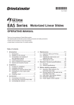
&20321(17#,'(17,),&$7,21
This manual refers to various connector terminals within the equipment which are accessible to the user for
installation purposes. An exploded view of a 620 Vector Drive is shown in Figure 1.1.
)L[LQJ#3RLQW
)L[LQJ#3RLQW
/&'
6WDWXV#/('V
00,
+/&'#.
%XWWRQV,
&KDVVLV#RU#6WDFN
3RZHU
7HUPLQDOV
&RQWURO#%RDUG#7HUPLQDOV
)L[LQJ#3RLQW
7HUPLQDO#&RYHU
)LJXUH#414#0#953#9HFWRU#'ULYH#([SORGHG#9LHZ
953#9HFWRU#'ULYH#0#+$7968;7
406
3URGXFW#2YHUYLHZ##
7(&+1,&$/#63(&,),&$7,21
The following paragraphs provide technical information regarding the features and performance characteristics of
the 620 Vector Drives.
*HQHUDO
The MMI display menus provides full access to all the drive's parameters.
Output Frequency
0-240Hz (for higher frequencies contact Eurotherm Drives Technical Support).
Switching Frequency
5 or 3kHz depending on type
Preset Speeds
8
Overload rating
150% for 60s
Speed control range
0-8 x base speed, 1000:1 of max. speed
Speed control precision
± 0.01% steady state of max. setpoint (digital setpoint)
± 0.1% steady state of max. setpoint (analogue setpoint).
Speed ref. resolution
± 0.01% digital
± 0.025% analogue (12 bit)
Stopping Modes
Ramp, Fast stop, Coast
3URWHFWLRQ
The 620 Vector series drives will trip under the following conditions:
•
Short circuit line - line
•
Short circuit line - earth
•
Earth fault
•
Overcurrent >220%
•
Overvoltage
•
Undervoltage
•
Stall
•
Overspeed
•
5703 repeater error
•
External trip
•
Heatsink overtemperature
•
Motor thermistor overtemperature
'LDJQRVWLFV#DQG#PRQLWRULQJ
Full diagnostics/monitoring is provided by the MMI display and status LEDs.
,QSXWV#DQG#2XWSXWV
The following range of inputs and outputs are provided:
•
5 Analogue Inputs (4 programmable)
•
2 Analogue Outputs (both programmable)
•
Digital Inputs (24V DC) for Run, Fast Stop, Coast Stop, Jog, Enable, Ramp Hold, Preset 1, 2, and 3 (the
last 4 inputs are programmable.
•
Three programmable digital outputs are provided (24V DC).
•
A 24V DC supply is available for interfacing external digital inputs.
•
A +10V and -10V DC supply is available for interfacing external analogue inputs.
•
2 or 4 wire RS-485 serial communications.
953#9HFWRU#'ULYH#0#+$7968;7
407#3URGXFW#2YHUYLHZ
(OHFWULFDO#5DWLQJV#0#3RZHU#&LUFXLW
,QSXW#9ROWDJH#6;39#WR#7939*#“43(/#83293+]
7<3(#7
7<3(#8
7<3(#9
7<3(#:
#3RZHU#+N:,
31:8
414
418
515
713
818
:18
44
48
4;
55
63
6:
78
88
:8
#,QSXW#&XUUHQW#+$,
613
718
913
;13
44
48
4;13
58
64
73
79
94
:5
<4
443
483
#2XWSXW#&XUUHQW#+$,
516
616
718
916
<17
46
49
57
63
6<
79
94
:5
<4
443
483
#,QSXW#SRZHU#IDFWRU
31<8
#,QSXW#)XVH2+&LUFXLW
#%UHDNHU,##+$,
31;9
43
#$SSUR[1#ORVV#+:,
93
:3
48
;8
443
483
53
533
#6ZLWFKLQJ
#)UHTXHQF\
583
734
734
834
964
4334 4584 4934
683
733
883
963
;53
5334
4383 4633 4933 5533
8N+]
6N+]
,QSXW#9ROWDJH#53;9#WR#5739-#“43(/#83293+]
7<3(#7
7<3(#8
7<3(#9
7<3(#:
#3RZHU#+N:,
31:8
414
418
515
713
818
:18
44
48
4;
55
63
6:
#,QSXW#&XUUHQW#+$,
818
:18
<18
45
4<
58
64
79
94
:5
;9
453
478
#2XWSXW#&XUUHQW#+$,
716
9
;
4318
4:
57
63
79
94
:5
;9
453
478
4584
4934
5334
<;3
4633
4933
#,QSXW#S1I1
31<8
#,QSXW#)XVH2+&LUFXLW
#%UHDNHU,##+$,
43
#$SSUR[1#ORVV#+:,
:3
31;9
48
<3
433
#6ZLWFKLQJ
#)UHTXHQF\
53
463
543
734
734
964
5:3
693
843
4334
9;3
8N+]
;63
6N+]
&RPPRQ#GDWD
7<3(#7
7<3(#8
7<3(#9
#2XWSXW#9ROWDJH
#+PD[,
,QSXW#9ROWDJH
#2XWSXW#2YHUORDG
483(#IRU#93V
#2XWSXW#)UHTXHQF\
3#WR#573+]
#$PELHQW#2SHUDWLQJ
3#WR#83ƒ&
#7HPSHUDWXUH#5DQJH
3#WR#73ƒ&#IRU#515N:#+6;3#0#7939,
#8/#7\SH#4
#(DUWK#/HDNDJH
#&XUUHQW
7<3(#:
3#WR#73ƒ&
!#83P$##$&1##3HUPDQHQW#3URWHFWLYH#(DUWKLQJ#5HTXLUHG
(* Suitable for earth referenced (TN) and non earth referenced (IT) supplies.)
7DEOH#405#0#953#(OHFWULFDO#6SHFLILFDWLRQV
Note:1
For installations requiring UL compliance, short circuit protection Semiconductor Fuses should be installed in
the 3-phase supply to the 620 products. These fuses are suitable for branch circuit short-circuit protection of the
solid-state motor controllers only. For installations NOT requiring UL compliance, use class"T" fuses or a circuit
breaker.
953#9HFWRU#'ULYH#0#+$7968;7
408
3URGXFW#2YHUYLHZ##
(OHFWULFDO#5DWLQJV#0#&RQWURO#&LUFXLW
The following ratings relate to all 620 variants.
6XSSOLHV
5HIHUHQFH#6XSSOLHV#+IRU#DOO#DQDORJXH#LQSXWV,
.439#±#3149/#43P$#PD[
0#439#±#3149/#43P$#PD[
6XSSO\#+IRU#DOO#GLJLWDO#LQSXWV,
.579#±#43(/#533P$
PD[1#7KLV#LV#LQ#DGGLWLRQ#WR
WKH#GLJLWDO#RXWSXWV1
7DEOH#406#5HIHUHQFH#,QSXWV
$QDORJXH#,22
,1387
287387
,PSHGDQFH
433NΩ
0LQ#ORDG#6NΩ#WR#3Y
5DQJH
±#439
±#439
5HVROXWLRQ
45#ELW#+4#LQ#73<9,#.#VLJQ
$SSUR[1#518P9#UHVROXWLRQ
45#ELW#+4#LQ#73<9,#.#VLJQ
6DPSOH#5DWH
6\QFKURQRXV#ZLWK#EORFN
GLDJUDP
6\QFKURQRXV#ZLWK#EORFN
GLDJUDP
7HUPLQDO#&7#+'LUHFW#,23,
414P61##+41:9P6#IRU#GULYH
VL]HV#:#DQG#XSZDUGV1,
&XUUHQW#+PD[1,
4P$
6P$
7DEOH#407#$QDORJXH#,QWHUIDFH#6SHFLILFDWLRQ
'LJLWDO#,QSXWV
,QSXW#YROWDJH
1RPLQDO#579#'&/#0D[1#.639#'&
,QSXW#LPSHGDQFH
7N:Ω
6DPSOH#5DWH
6\QFKURQRXV#ZLWK#EORFN#GLDJUDP
7KUHVKROG
9 #ORZ#?.99#'&
7\SLFDO#.459#'&
9LQ#KLJK#!.4;9#'&
7DEOH#408#'LJLWDO#,QSXWV
'LJLWDO#2XWSXWV
Digital outputs are open circuit when Off. The On specification is shown in Table 1-7.
2Q#9ROWDJH
.579#±43(
0D[LPXP#2Q#&XUUHQW
83P$#+6RXUFH,
6KRUW#&LUFXLW#'XUDWLRQ
,QGHILQLWH
7DEOH#409#'LJLWDO#2XWSXWV
953#9HFWRU#'ULYH#0#+$7968;7
409#3URGXFW#2YHUYLHZ
3LORW#2XWSXW
Pilot output is an open collector output that is off while the drive is healthy. The specification is shown in Table
1-7.
2SHQ#&ROOHFWRU#39#WR#579
83P$#+&XUUHQW#6LQN,1
7DEOH#40:##3LORW#2XWSXW
(QFRGHU#,QSXWV
,QSXW#9ROWDJH
0639#WR#.639#GLIIHUHQWLDO
,QSXW#7KUHVKROG#9ROWDJH
79#±#49#',/#:045#VZLWFK#RQ
<9#±#49#',/#:045#VZLWFK#RII
,QSXW#&XUUHQW
43P$#±#6P$
0D[LPXP#,QSXW#)UHTXHQF\
583N+]#RQ#HDFK#RI#$#DQG#%
MaxFreq =
MaxSpeedRPM
* NoOfLines
60
7DEOH#40;##&RQWURO#7HUPLQDO#6SHFLILFDWLRQV
(QFRGHU#6XSSO\#2XWSXW
2XWSXW#9ROWDJH
43#0#549#+3#WR#533P$#ORDG,
499#±#49#+5HFRPPHQGHG#ORDG,1
7KH#2XWSXW#9ROWDJH#PD\#EH#VHW#E\
DOWHULQJ#WKH#YDULDEOH#´6HWXS
3DUDPHWHUV==&DOLEUDWLRQ==(QFRGHU
6XSSO\µ1
5HFRPPHQGHG#/RDG#&XUUHQW
83#0#533P$
6KRUW#&LUFXLW#'XUDWLRQ
,QGHILQLWH
7DEOH#40<#(QFRGHU#6XSSO\#2XWSXW#6SHFLILFDWLRQV
6HULDO#,QWHUIDFH
9ROWDJH#/HYHOV
5607;8
,VRODWLRQ#IURP#RWKHU#WHUPLQDOV
!#40Ω
0D[1#ZLWKVWDQG#YROWDJH#WR#DQ\#RWKHU#FRQWURO
WHUPLQDO
63Y#506
7DEOH#4043#(QFRGHU#6XSSO\#2XWSXW#6SHFLILFDWLRQV
953#9HFWRU#'ULYH#0#+$7968;7
40:
3URGXFW#2YHUYLHZ##
0HFKDQLFDO#'HWDLOV
The mechanical details of all the 620 vector series controllers are shown in Tables 1-11 to 1-14. The general
layout of the cases is shown in Chapter 3.
953#7<3(#7
',0(16,216
02817,1*#25,(17$7,21
:(,*+7
$,5#)/2:#&/($5$1&(
32:(5#7(50,1$7,216
5HIHU#WR#ILJXUH#614
9HUWLFDO
;NJ#PD[1
5HIHU#WR#ILJXUH#614
08#VORWWHG#VFUHZV1
7LJKWHQLQJ#WRUTXH#5181P#+5514OE0LQ/#41;OE0IW,1
($57+#+*5281',
*ODQG#ER[#QRW#ILWWHG=#5#[#07#EROW#DQG#ZDVKHU/#WLJKWHQLQJ
*ODQG#ER[#QRW#ILWWHG=
7(50,1$7,216
WRUTXH#4161P#+4418OE0LQ/#31<OE0IW,#DQG#08#VORWWHG#VFUHZ#DQG
ZDVKHU/#WLJKWHQLQJ#WRUTXH#5181P#+5514OE0LQ/#41;OE0IW,1
*ODQG#ER[#ILWWHG=##5#[#08#VWXG/#QXW#DQG#ZDVKHU/#WLJKWHQLQJ
*ODQG#ER[#ILWWHG=
WRTXH#5181P#+5514OE0LQ/#41;OE0IW,#DQG#08#VORWWHG#VFUHZ#DQG
ZDVKHU/#WLJKWHQLQJ#WRUTXH#5181P#+5514OE0LQ/#41;OE0IW,1
5
&21752/#7(50,1$7,216
5HPRYDEOH#VFUHZ#FRQQHFWRUV#IRU#31:8PP #ZLUH1
5
7HUPLQDOV#ZLOO#DFFHSW#XS#WR#616PP #ZLUH#+45#$:*,1
7LJKWHQLQJ#WRUTXH#3189031:<1P#+80:OE0LQ/#31750318;OE0IW,1
6SULQJ#WHUPLQDO#FRQQHFWRUV1
5
7HUPLQDOV#ZLOO#DFFHSW#XS#WR#31;PP #ZLUH#+4;#$:*,1
7DEOH#4044##953#W\SH#7#PHFKDQLFDO#GHWDLOV
953#7<3(#8
',0(16,216
02817,1*#25,(17$7,21
:(,*+7
$,5#)/2:#&/($5$1&(
32:(5#7(50,1$7,216
5HIHU#WR#ILJXUH#614
9HUWLFDO
45NJ
5HIHU#WR#ILJXUH#614
08#VORWWHG#VFUHZV1
7LJKWHQLQJ#WRUTXH#5181P#+5514OE0LQ/#41;OE0IW,1
($57+#+*5281',
*ODQG#ER[#QRW#ILWWHG=#5#[#08#QXW#DQG#ZDVKHU/#WLJKWHQLQJ
*ODQG#ER[#QRW#ILWWHG=
7(50,1$7,216
WRUTXH#5181P#+5514OE0LQ/#41;OE0IW,1
*ODQG#ER[#ILWWHG=##5#[#08#VWXG/#QXW#DQG#ZDVKHU/#WLJKWHQLQJ
*ODQG#ER[#ILWWHG=
WRTXH#5181P#+5514OE0LQ/#41;OE0IW,1
5
&21752/#7(50,1$7,216
5HPRYDEOH#VFUHZ#FRQQHFWRUV#IRU#31:8PP #ZLUH1
5
7HUPLQDOV#ZLOO#DFFHSW#XS#WR#616PP #ZLUH#+45#$:*,1
7LJKWHQLQJ#WRUTXH#3189031:<1P#+80:OE0LQ/##31750318;OE0IW,
6SULQJ#WHUPLQDO#FRQQHFWRUV1
5
7HUPLQDOV#ZLOO#DFFHSW#XS#WR#31;PP #ZLUH#+4;#$:*,1
7DEOH#4045##953#W\SH#8#PHFKDQLFDO#GHWDLOV
953#9HFWRU#'ULYH#0#+$7968;7
40;#3URGXFW#2YHUYLHZ
953#7<3(#9
',0(16,216
02817,1*#25,(17$7,21
:(,*+7
$,5#)/2:#&/($5$1&(
32:(5#$1'#($57+
+*5281',#7(50,1$7,216
&21752/#7(50,1$7,216
5HIHU#WR#ILJXUH#614
9HUWLFDO
64NJ
5HIHU#WR#ILJXUH#614
&RPSDFW#KLJK#FXUUHQW#WHUPLQDO#EORFNV1
5
7HUPLQDOV#DFFRPPRGDWH#ZLUH#UDQJH#31;#0#8618PP #+4;#0#423
$:*,1
7LJKWHQLQJ#WRUTXH#617#0#8191P#+63#0#83OE0LQ/##518#0#715OE0IW,1
5
5HPRYDEOH#VFUHZ#FRQQHFWRUV#IRU#31:8PP #ZLUH1
5
7HUPLQDOV#ZLOO#DFFHSW#XS#WR#616PP #ZLUH#+45#$:*,1
7LJKWHQLQJ#WRUTXH#3189#0#31:<1P#+80:OE0LQ/#31750318;OE0IW,1
6SULQJ#WHUPLQDO#FRQQHFWRUV1
5
7HUPLQDOV#ZLOO#DFFHSW#XS#WR#31;PP ##ZLUH#+4;#$:*,1
7DEOH#4046#953#W\SH#9#PHFKDQLFDO#GHWDLOV
953#7<3(#:
',0(16,216
02817,1*#25,(17$7,21
:(,*+7
$,5#)/2:#&/($5$1&(
32:(5#$1'#($57+
+*5281',#7(50,1$7,216
5HIHU#WR#ILJXUH#614
9HUWLFDO
;6NJ
5HIHU#WR#ILJXUH#614
+D, 6XSSO\#+/406,/#0RWRU#+0406,/#%UDNH#+'%4/5,#WHUPLQDOV=
&RPSDFW#KLJK#FXUUHQW#WHUPLQDO#EORFNV1
5
7HUPLQDOV#DFFRPPRGDWH#ZLUH#UDQJH#6619043:15PP
+50723#$:*,
7LJKWHQLQJ#WRUTXH#531P#+4:8OE0LQ/#4719OE0IW,1
+E, '1&1#LQWHUFRQQHFWLRQ#WHUPLQDOV#+'&./#'&0,=
&RPSDFW#KLJK#FXUUHQW#WHUPLQDO#EORFNV1
5
7HUPLQDOV#DFFRPPRGDWH#ZLUH#UDQJH#66190485PP
+5$:*0633NFPLO#+0&0,,
7LJKWHQLQJ#WRUTXH#63181P#+5:3OE0LQ/#5518OE0IW,
(DUWK#+JURXQG,# #=
&RPSDFW#KLJK#FXUUHQW#WHUPLQDO#EORFNV1
5
7HUPLQDOV#DFFRPPRGDWH#ZLUH#UDQJH#6619043:15PP
+50723#$:*,#WLJKWHQLQJ#WRUTXH#55191P#+533OE0LQ/#
491:OE0IW,1
5
&21752/#7(50,1$7,216
5HPRYDEOH#VFUHZ#FRQQHFWRUV#IRU#31:8PP #ZLUH#1
5
7HUPLQDOV#ZLOO#DFFHSW#XS#WR#616PP #ZLUH#+45#$:*,1
7LJKWHQLQJ#WRUTXH#3189031:<1P#+80:OE0LQ/#31750318;OE0IW,1
6SULQJ#WHUPLQDO#FRQQHFWRUV1
5
7HUPLQDOV#ZLOO#DFFHSW#XS#WR#31;PP #ZLUH#+4;#$:*,1
7DEOH#4047##953#W\SH#:#PHFKDQLFDO#GHWDLOV
+F,
(1&/2685(
,353#+DV#VWDQGDUG,/#WR#EH#EXLOW#LQWR#D#VXLWDEOH#FXELFOH1
,373#+ZLWK#8/#7\SH#4#WRS#FRYHU,#7\SH#7/8/9#DQG#:#RQO\/#VXLWDEOH#IRU#ZDOO#PRXQWLQJ#LQ#(XURSH1
(0SHFLILFDWLRQ
5HIHU#WR#&KDSWHU#:1
953#9HFWRU#'ULYH#0#+$7968;7
40<
3URGXFW#2YHUYLHZ##
+,*+#32:(5#$&#+W\SHV#;/#<#DQG#43,
HPAC Product Manual HA463284 details the technical specification of these builds, the following is for
information only.
(OHFWULFDO#5DWLQJV#0#3RZHU#&LUFXLWV#+953#
(OHFWULFDO#5DWLQJV#0#3RZHU#&LUFXLWV#+953#&RQVWDQW#7RUTXH,
953#&RQVWDQW#7RUTXH,
7<3(#;
7<3(#<
7<3(#43
6;39#WR#7939#4“43(/#83293+]
,QSXW#9ROWDJH
3URGXFW#&RGH#%ORFN#5
3<33
4433 4653 4933
4;33 5333 5833 5;33
1RPLQDO#0RWRU#3RZHU#+N:,###6;39
<3
443
465
493
4;3
533
583
5;3
1RPLQDO#0RWRU#3RZHU#+N:,###74827739
<3
443
483
4;8
533
553
5;3
648
0RWRU#3RZHU#++S,###7939#+DV#VSHFLILHG
ZLWKLQ#1(&21)3$0:3,
483
483
533
583
633
633
733
783
2XWSXW#&XUUHQW#+$,
4;3
549
583
649
694
6:8
7;3
853
,QSXW#&XUUHQW#+$,#56
4;3
553
593
653
693
733
7<3
883
)XQGDPHQWDO#,QSXW#3RZHU#)DFWRU
5
,QSXW#%ULGJH#, W
31<8
5
5
578#333#$ V
;46#333#$ V
)XVH#5DWLQJ2&LUFXLW#%UHDNHU#7+$,
533
583
633
683
733
783
883
933
$SSUR[1#ORVV###6N+]#+N:,
517
51<
618
716
71;
817
91:
:18
6ZLWFKLQJ#)UHTXHQF\
6N+]
2XWSXW#9ROWDJH#+PD[,
,QSXW#9ROWDJH
2XWSXW#2YHUORDG
483(#IRU#93#VHFRQGV
2XWSXW#)UHTXHQF\
3#WR#453+]
)DQ#,QOHW#WHPSHUDWXUH#5DQJH
,3#5DWLQJ
(DUWK#/HDNDJH#&XUUHQW
3#WR#73°&
,353#(QFORVXUH#,333#SRZHU#WHUPLQDOV
!!433P$1##3URGXFW#PXVW#EH#SHUPDQHQWO\#HDUWKHG
7DEOH#4048
1
Suitable for earth referenced (TN) and non earth referenced (IT) supplies
2 IMPORTANT: 3% line impedance MUST be provided for each module, and is assumed in the quoted
input current values. Failure to do so will severely curtail DC link capacitor lifetime and could result in damage
to the input bridge.
3
Input current quoted is for 380V supply at the stated motor power. Motor efficiency of 93% is assumed
4
Short circuit protection Semiconductor Fuses should be installed in the 3-phase supply to the drive module to
protect the input bridge. Circuit breakers or HRC fuses will not protect the input bridge.
953#9HFWRU#'ULYH#0#+$7968;7
4043#3URGXFW#2YHUYLHZ
6SHFLDO#&RQVLGHUDWLRQV#)RU#,QVWDOODWLRQV#5HTXLULQJ#&RPSOLDQFH#ZLWK#8/#6WDQGDUGV
Motor Overload Protection
An external motor overload protective device must be provided by the installer.
Motor overload protection is provided in the controller by means of the thermal device in the motor winding.
This protection cannot be evaluated by UL hence it is the responsibility of the installer and/or the local inspector
to determine whether the overload protection is in compliance with the National Electrical Code or Local Code
requirements.
Branch Circuit/Short Circuit Protection Requirements
Model 620 Type 4 Series
UL Listed (JDDZ) non-renewable cartridge fuses or UL Listed (JDRX) renewable cartridge fuses, rated 300Vac
or 600Vac as appropriate (depending on the rated input voltage of the drive), must be installed upstream of the
drive. For fuse current ratings, see Chapter 1 “Electrical Ratings - Power Circuit”.
Model 620 Type 5 and 6 Series
UL Recognized Component (JFHR2) semiconductor fuses must be installed upstream of the drive. For fuse
current ratings, see Chapter 1 “Electrical Ratings - Power Circuit”. Refer to Table 1-16 below for recommended
semiconductor fuse manufacturer and model numbers.
Fuse Current Rating
Bussmann Model No.
170M3808
40A
170M3809
50A
170M3810
63A
170M3812
100A
170M3813
125A
7DEOH#4049#0#%XVVPDQQ#,QWHUQDWLRQDO#)XVHV#+5DWHG#9939DF,
Model 620 Type 7 Series
These devices are provided with solid state short circuit (output) protection. Branch circuit protection should be
provided as specified in the National Electrical Code, NEC/NFPA-70.
Short Circuit Ratings
Model 620 Type 4, 5, 6 Series.
Suitable for use on a circuit capable of delivering not more than 5000 RMS Symmetrical Amperes, 240/460V
maximum.
Model 620 Type 7 Series.
Suitable for use on a circuit capable of delivering not more than (the value shown in Table 1- 17) RMS
Symmetrical Amperes, (the value of rated voltage shown in Table 1- 17)V maximum.
Output Rating - kW
Rated Voltage - V
Short Circuit Rating RMS Symmetrical Amperes
22 - 37
45 - 75
208 - 240
380 - 460
5,000
10,000
7DEOH#404:
Field Wiring Temperature Rating
Model 620 Type 4, 5, 6 Series - Use 60oC copper conductors only.
Model 620 Type 7 Series - Use 75oC copper conductors only.
Motor Base Frequency
The motor base frequency rating is 240Hz maximum.
Operating Ambient Temperature
For operating ambient temperature range, see “Electrical Ratings - Power Circuit” on page 1-4
Environmental Rating
Model 620 Type 4, 5, 6, 7 Series with a Product Code Block IV designation xx2x are suitable for direct wallmounting as they have a “Type 1 Enclosure” rating.
953#9HFWRU#'ULYH#0#+$7968;7
4044
3URGXFW#2YHUYLHZ##
In order to preserve this enclosure rating, it is important to maintain the environmental integrity of the enclosure.
The installer must provide correct Type 1 closures for all unused clearance/knockout holes within the drive
glandbox.
Additionally, in order to preserve the “Type 1 Enclosure” rating for 620 Type 7 models, the installer must ensure
that the blanking plates are fitted to the ventilation apertures provided within the glandbox.
(QYLURQPHQWDO#5HTXLUHPHQWV
The environmental limits for the 620 Vector series controllers are shown in Table 1-18.
+XPLGLW\#+PD[1,
;8(#UHODWLYH#KXPLGLW\#+QRQ0FRQGHQVLQJ,#DW#73°&
$ERYH#4333P#GHUDWH#SRZHU#E\#4(#SHU#433P#XS#WR#D
PD[LPXP#8333P
1RQ#IODPPDEOH/#QRQ#FRUURVLYH#DQG#GXVW#IUHH#+3ROOXWLRQ
'HJUHH#5,
$OWLWXGH
$WPRVSKHUH
2SHUDWLQJ#WHPSHUDWXUH#UDQJH
3°&#WR#83°&
3°&#WR#73°/#7\SH#4#RSWLRQ#ILWWHG
6WRUDJH#WHPSHUDWXUH
0LQLPXP#058°&#WR#PD[LPXP#.88°&
7UDQVSRUW#WHPSHUDWXUH
0LQLPXP#058°&#WR#PD[LPXP#.:3°&
,353#+GLUHFW#FRQGXLW#FRQQHFWLRQ#DQG#8/#7\SH#4#RSWLRQV,
&ODVV#6N6#DV#GHILQHG#E\#(1834:;#+4<<;,
5
6
(QFORVXUH
&OLPDWLF#&RQGLWLRQV
3ROOXWLRQ#'HJUHH
,QVWDOODWLRQ#2#2YHUYROWDJH#&DWHJRU\
7DEOH#404;#953#6HULHV#HQYLURQPHQWDO#UHTXLUHPHQWV
3URGXFW##&RGH
All 620 units are fully identified using an eleven block alphanumeric code, as shown in figure 1-2. This code
details the drive calibration and settings on despatch from the factory. The product code appears as the "Model
No." on the rating label at the side of the unit.
([DPSOH#&RGH
%ORFN#1XPEHU
95367' 23:83 2733
4
5
6
23343
28.
2(1:
23333
2333
2%4
2333
2333
7
8
9
:
;
<
43
44
)LJXUH#405#3URGXFW#FRGH#EORFNV
Details of each block of the product code are given in Table 1-19.
%ORFN#1R1
4
5
9DULDEOH
95367'
953&20
953/
953$'9
333:
3344
3348
3355
3373
3388
33:8
3443
3483
34;3
3553
3633
36:3
3783
3883
3:83
953#9HFWRU#'ULYH#0#+$7968;7
'HVFULSWLRQ
953#9HFWRU#6WDQGDUG
953#9HFWRU#&RPPXQLFDWLRQV
953#9HFWRU#/LQN
953#$GYDQFH#'ULYH#+QRW#DYDLODEOH#IRU#QHZ#GHVLJQV,
)RXU#QXPEHUV#VSHFLI\LQJ#WKH#SRZHU#UDWLQJ#LQ#N:
31:8#N:
414#N:
418#N:
515#N:
713#N:
818#N:
:18#N:
44#N:
48#N:
4;#N:
55#N:
63#N:
6:#N:
78#N: +6;307939#RQO\,
88#N: +6;307939#RQO\,
:8#N: +6;307939#RQO\,
4045#3URGXFW#2YHUYLHZ
%ORFN#1R1
6
9DULDEOH
7KUHH#QXPEHUV#VSHFLI\LQJ#WKH#QRPLQDO#LQSXW#YROWDJH#UDWLQJ
53;#WR#5739#+±43(,#83293+]
6;3#WR#7939#+±43(,#83293+]
563
733
)RXU#GLJLWV#VSHFLI\LQJ#WKH#PHFKDQLFDO#SDFNDJH#LQFOXGLQJ#OLYHU\#DQG
PHFKDQLFDO#SDFNDJH#VW\OH
7
33[[
34[[0<<[[
[[4[
[[5[
[[6[
[[8[
[[9[
8.
7ZR#FKDUDFWHUV#VSHFLI\LQJ#WKH#XVHU#LQWHUIDFH#ODQJXDJH
7KHVH#FKDUDFWHUV#DUH#WKH#VDPH#DV#XVHG#IRU#FRPSXWHU#NH\ERDUG
VSHFLILFDWLRQV=
(QJOLVK#83+]#GHIDXOW
9
(1:
3333
12$
)RXU#FKDUDFWHUV#VSHFLI\LQJ#WKH#FRPPXQLFDWLRQV#SURWRFRO#DQG#LWV
KDUGZDUH#LPSOHPHQWDWLRQ#PHWKRG
1R#FRPPXQLFDWLRQV#RSWLRQV#ILWWHG
,QGLFDWHV#WKH#SDUWLFXODU#FRPPXQLFDWLRQV#RSWLRQ
333
12$
7KUHH#FKDUDFWHUV#VSHFLI\LQJ#DQ\#RSWLRQDO#ORDGHG#VRIWZDUH
1R#VRIWZDUH#RSWLRQV#ORDGHG
,QGLFDWHV#WKH#SDUWLFXODU#VRIWZDUH#RSWLRQ
33
%3
%4
44
(QJOLVK#93+]#GHIDXOW
7KUHH#FKDUDFWHUV#VSHFLI\LQJ#DQ\#IHHGEDFN#RSWLRQ#LQVWDOOHG#RYHU#DQG
DERYH#WKH#VWDQGDUG#IHDWXUHV#RI#WKH#SURGXFW/#H1J1
(QFRGHU#+:LUH0HQGHG,
:
43
7KLUG#GLJLW=
0HFKDQLFDO#SDFNDJLQJ#VW\OH
6WDQGDUG#+,353,/#SURWHFWHG#SDQHO#PRXQWLQJ
,353#DQG#IDOOLQJ#GLUW#SURWHFWLRQ#+8/#7\SH4,#ZLWK
JODQGSODWH#FDEOH#HQWU\
(QFORVHG#+,353,/#WKURXJK#SDQHO#PRXQWLQJ
,353#ZLWK#IDOOLQJ#GLUW#SURWHFWLRQ#RQO\
,353#ZLWK#JODQGFDEOH#HQWU\#RQO\
1RWH=#2SWLRQ#6#DSSOLHV#WR#W\SH#:#SRZHU#UDWLQJV#RQO\1
)RXUWK#GLJLW=
2SHUDWRU#6WDWLRQ
6WDQGDUG#SURGXFW#+DOZD\V#3,#0#%XLOW#LQ#00,
86
<
)LUVW#WZR#GLJLWV= /LYHU\
6WDQGDUG#(XURWKHUP#'ULYHV#OLYHU\
'HILQHG#FXVWRPHU#OLYHULHV
[[[3
8
;
'HVFULSWLRQ
7ZR#FKDUDFWHUV#VSHFLI\LQJ#WKH#EUDNLQJ#RSWLRQ
%UDNH#SRZHU#VZLWFK#QRW#ILWWHG
%UDNH#SRZHU#VZLWFK#ILWWHG#0#QR#EUDNLQJ#UHVLVWRUV
VXSSOLHG
%UDNH#SRZHU#VZLWFK#ILWWHG#DQG#GHIDXOW#YDOXH#EUDNLQJ#
UHVLVWRUV#VXSSOLHG##+UHFRPPHQGHG,
+UHFRPPHQGHG,
1RWH=#([WUD#EUDNLQJ#UHVLVWRUV#FDQ#EH#VSHFLILHG#DQG#RUGHUHG
VHSDUDWHO\
333
7%$
7KUHH#FKDUDFWHUV#VSHFLI\LQJ#WKH#DX[#VXSSO\#UHTXLUHG
1R#DX[#VXSSO\#RSWLRQ#ILWWHG
&RGH#IRU#WKH#ILOWHULQJ#RSWLRQ#LQVWDOOHG
333
QQQ
6#GLJLWV#VSHFLI\LQJ#HQJLQHHULQJ#VSHFLDO#RSWLRQV=
1R#VSHFLDO#RSWLRQV
&RGH#IRU#WKH#VSHFLDO#HQJLQHHULQJ#RSWLRQ#LQVWDOOHG
7DEOH#404<#0#3URGXFW#&RGH#%ORFN#'HVFULSWLRQV
953#9HFWRU#'ULYH#0#+$7968;7
4046
3URGXFW#2YHUYLHZ##
([DPSOH#&RGH=
620STD/0750/400/0010/UK/ENW/0000/000/B1/000/000
This code indicates a drive, which is:
•
a 620 Standard product
•
75kW power rating
•
380-460v input supply
•
Eurotherm Drives livery
•
Enclosed mechanical package (IP20)
•
No additional optional operator station
•
UK language
•
Wire-ended 15V encoder option
•
No optional communications
•
No optional loaded software
•
Brake switch fitted with default value resistors supplied
•
No aux supply option fitted
•
No special options.
953#9HFWRU#'ULYH#0#+$7968;7
4047#3URGXFW#2YHUYLHZ
953#9HFWRU#'ULYH#0#+$7968;7
504
3UH0,QVWDOODWLRQ#3ODQQLQJ##
&KDSWHU#5##3UH0,QVWDOODWLRQ#3ODQQLQJ
,1752'8&7,21
This chapter contains a functional description of the 620 Vector Drive to enable a sound understanding of the
system, and notes for consideration prior to installation.
)81&7,21$/#29(59,(:
The 620 Vector enables very high performance control of 3-phase AC induction motors fitted with a compatible
encoder. It offers the user great system flexibility, allowing easy integration into various control schemes. The plain
language Man-Machine Interface (MMI) greatly simplifies setting up and commissioning the 620 Vector.
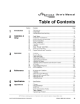
A simplified block diagram of a 620 is shown in Figure 2.13. This illustrates the basic internal arrangement of the
drive with the circuitry split between the control circuits and power circuits.
The control circuits are common to all types of the 620 Vector Drive.
Chassis types 5 and 7 use a slightly different power circuit from types 4 and 6. The general principles of operation
remain the same, however.
&RQWURO#&LUFXLWV#DQG#6RIWZDUH
The control circuits and software element contain the intelligence of the 620 Vector series. They comprise a
sophisticated microprocessor system with digital and analogue inputs and outputs, the MMI and circuits to interface
between the microprocessor and the inverter circuits.
Speed feedback signals from the motor shaft encoder are processed by the microprocessor to determine the rotational
speed of the shaft. An PI algorithm within the software uses this information to produce varying gate drive signals to
the inverter circuits. These signals cause the inverter to output the required voltage and frequency for a particular
motor speed.
Analogue inputs to the microprocessor are digitised and can be used to set parameters such as speed.
Digital inputs to the microprocessor signal various commands and conditions such as stop, start and required
direction of rotation.
Digital outputs from the microprocessor (e.g. Health) can be used by external control equipment.
A detailed block diagram of the logical blocks which comprise the control circuits and software is shown in Figure
2.13.
3RZHU#&LUFXLWV
The 3-phase supply input on terminals L1, L2 and L3 is rectified to give a DC output to the DC Link capacitors,
which smooth the DC power. The DC power is fed to the inverter circuits, which convert the fixed voltage DC into
three phase variable frequency and voltage drive outputs to the motor. The frequency and voltage are set by the gate
drive signals from the microprocessor.
During motor deceleration or at other times when the motor acts as a generator, energy flows from the motor into the
DC link capacitors and causes the DC link voltage to rise. The drive will trip if the DC link voltage rises above a
pre-set level, to avoid damage to the drive.
'\QDPLF#%UDNLQJ
If the dynamic braking option is fitted, an external brake resistor is switched across the DC Link by the Dynamic
Brake Switch to dissipate the excess energy and prevent the drive from tripping.
Chapter 3 describes the power and resistance rating requirements for the dynamic braking resistor.
%XLOW0LQ#GLDJQRVWLFV
Number and logic diagnostics are values and settings that can be displayed via the diagnostic menu within the MMI.
These values are read-only and are provided for the user to determine operating or fault conditions. Refer to
Chapter 6 for further information and descriptions of the diagnostics.
953#9HFWRU#'ULYH#0#+$7968;7
505##3UH0,QVWDOODWLRQ#3ODQQLQJ
A
D
Control
Inputs /
Output
Speed.
Feedback
Ref.
Encoder
MMI
B
C
E
Control Circuits
& Software
F
Input
3 Phase
Supply
L2
M1/U
DC+
L1
3 Phase
Rectifier
DC-
DC
Inverter
Circuits
L3
M2/V
Motor
Drive
Outputs
M3/W
Internal DC
Link choke
DC+
Protective Earth
Dynamic
Brake
Circuit
Brake
resistor
DBR1
This connection is
made when the
braking option is not
fitted.
DC-
)LJXUH#514#0#7\SH#7#6LPSOLILHG#%ORFN#'LDJUDP
Input
3 Phase
Supply
L2
M1/U
DC+
L1
3 Phase
Rectifier
DC-
DC
Inverter
Circuits
L3
M2/V
Motor
Drive
Outputs
M3/W
Internal DC
Link choke
DC+
Protective Earth
Dynamic
Brake
Circuit
Brake
resistor
DBR1
DC
DC-
)LJXUH#515#0#7\SH#8#6LPSOLILHG#%ORFN#'LDJUDP
953#9HFWRU#'ULYH#0#+$7968;7
506
3UH0,QVWDOODWLRQ#3ODQQLQJ##
Input
3 Phase
Supply
L2
M1/U
DC+
L1
3 Phase
Rectifier
DC-
DC
Inverter
Circuits
L3
M2/V
Motor
Drive
Outputs
M3/W
Internal DC
Link choke
DC+
Protective Earth
Dynamic
Brake
Circuit
Brake
resistor
DBR1
This connection is
made when the
braking option is not
fitted.
DC-
)LJXUH#516#0#7\SH#9#6LPSOLILHG#%ORFN#'LDJUDP
Input
3 Phase
Supply
L2
M1/U
DC+
L1
3 Phase
Rectifier
DC-
DC
Inverter
Circuits
L3
M2/V
Motor
Drive
Outputs
M3/W
Internal DC
Link choke
DC+
Protective Earth
DBR2
Dynamic
Brake
Circuit
Brake
resistor
DBR1
DC
DC-
)LJXUH#517#0#7\SH#:#6LPSOLILHG#%ORFN#'LDJUDP
953#9HFWRU#'ULYH#0#+$7968;7
507##3UH0,QVWDOODWLRQ#3ODQQLQJ
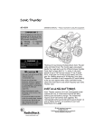
,167$//$7,21#:,5,1*#',$*5$06
This section shows all the necessary wiring details for connecting up a 620 Vector series drive.
Figure 2.5 shows the minimum configuration required for basic operation of the Drives.
Figure 2.6 shows a full connection diagram to utilise all the features of the Drives.
1. To PE or
2. terminal A9
To be installed as
per manufacturers
instructions.
ENCODER
B
B
A
A
Encoder
PE
L2
L3
L1
*
LABELLED DB1 & DB2
ON TYPE 7
CHASSIS
GND
A1 A2 A3 A4 A7 A8
RAM
P
SPEED
C3
B4
C1
C2
B5
C6
F.STOP
E.STOP
FAST
STOP
COAST
STOP
MCB1
+HQJVWOHU#(QFRGHUV#DUH#UHFRPPHQGHG
UHIHU#WR#(XURWKHUP#'ULYHV#IRU#PRUH
LQIRUPDWLRQ1
MOTOR
THERMISTOR
E
0V
+
15V
A8
A7
A4
A3
A2
A1
620 VECTOR DRIVE
B9
B7
START
B8
24V
MOTOR
M
M1/U M2/V M3/W
B1
*
*
A9
DC+
DBR
BRAKE
RESISTOR
ASSY
.
DYNAMIC
BRAKING
DC-
B2
E
E
L1
L2
L3
FILTER
(OPTIONAL)
All the 620 Vector Drives are wired similarly. The main difference between the variants (other than power rating
and physical size) is the capacity of the upstream circuit breaker (MCB1 in Figure 2.6) and the layout of the power
terminals. The MCB details are listed in Table 2-1, and the power terminals are shown in Figures 2.9 to 2.12.
)LJXUH#518#0#0LQLPXP#ZLULQJ#FRQILJXUDWLRQ#IRU#953#VHULHV#GULYHV
953#9HFWRU#'ULYH#0#+$7968;7
953#9HFWRU#'ULYH#0#+$7968;7
C6
+10V
F1
B3
F6
CON1
F4
F3
B5
ANALOGUE I/P 5
ANALOGUE I/P 4
F2
MCB2
B6
C1
F.STOP
JOG
RAMP I/P 1
0V
0V
V
C5
SPEED
FEEDBACK
C2
B7
START
E1
TORQUE
DEMAND
V
F5
B8
CON1
ENABLE
RL S
DIG O/P2
DRIVE
HEALTHY
DIG O/P1
ZERO
SPEED
E7
RL S
E8
E3
1
DIG O/P3
DRIVE
READY
620 VECTOR DRIVE
E2
RL S
E6
B9
RAMP
HOLD
A
A1
E4
A
A2
RAMP I/P 2
-10V
)LJXUH#519#0#)XOO#ZLULQJ#GLDJUDP#IRU#953#VHULHV#GULYHV
B
A4
E9
ENCODER
B
A3
E5
PRESET INPUTS
2
3
+15V
A7
A8
*
0V
DBR
A9
B2
MOTOR
B1
*
DC+ DC-
BRAKE
RESISTOR
ASSY.
DYNAMIC BRAKING
(OPTIONAL)
E
E
E
L2
L3
I
MOTOR
M
I
I
M1/U M2/V M3/W
L1
FILTER
CON1
MCB2
OPTIONAL
)XOO#,QVWDOODWLRQ
* LABELLED DB1 & DB2
ON TYPE 7 CHASSIS
C4
B4
DIRECT I/P
C3
24VDC
50mA
FAST
STOP
E.STOP
COAST
STOP
MCB1
PILOT RELAY
(OPTIONAL)
PE
L3
L2
L1
3UH0,QVWDOODWLRQ#3ODQQLQJ##
508
509##3UH0,QVWDOODWLRQ#3ODQQLQJ
'LIIHUHQFHV#EHWZHHQ#'ULYHV
Each of the drive variants requires different rating breakers for MCB1. The requirements are shown in Table 2-1.
(Entries with N/A indicate that the drive rating is not available for that type at that voltage.)
MCB2 should be rated according to the full load current of the motor.
7DEOH#504##0&%#UHTXLUHPHQWV
7\SH
7
8
9
:
3RZHU#+N:,
31:8
414
418
515
713
818
:18
818
:18
4413
4813
4413
4813
4;13
4;18
5513
6313
6:13
5513
6313
6:13
7813
8813
:813
53;0573Y
43#$
43#$
43#$
53#$
53#$
12$
12$
63#$
73#$
12$
12$
96#$
433#$
12$
433#$
12$
12$
12$
458#$
493#$
533#$
12$
12$
12$
6;30793Y
43#$
12$
53#$
43#$
53#$
53#$
53#$
12$
12$
65#$
73#$
12$
12$
83#$
12$
96#$
433#$
433#$
12$
12$
12$
458#$
493#$
533#$
953#9HFWRU#'ULYH#0#+$7968;7
50:
3UH0,QVWDOODWLRQ#3ODQQLQJ##
7(50,1$/#'(6&5,37,216
Terminals are provided for both the control and power connections to allow reliable connections with external
devices and power supplies. The function of these terminals is described in tables 2.2 to 2.7.
&RQWURO#%RDUG#7HUPLQDOV
The control board terminals are identical for all variants of the 620 Vector Drive. The layout of the control board
terminals is given in Figure 2.8, and the functions are described in Table 2.5. See Chapter 1 "ELECTRICAL
RATINGS" for control terminal specification.
D
E
F
Peek
Pri
0v
A
P1
Link
Encoder
B
C
Digital
Analogu
RS485
P3
RS232
)LJXUH#51:#0#&RQWURO#%RDUG#7HUPLQDOV
34
5607;8#6HULDO#3RUW
)URQW#2
/RZHU
4
5
6
7
%DFN#2
8SSHU
12$
12$
12$
12$
7UDQVPLW#0
7UDQVPLW#.
7UDQVPLW#0#2#5HFHLYH#0
7UDQVPLW#.#2#5HFHLYH#.
/LQN#)LEUH#2SWLFV1
+953/#RQO\,
5HG
%ODFN
12$
12$
7UDQVPLW#3ULPDU\
5HFHLYH#3ULPDU\
)HHGEDFN#(QFRGHU
$
%
&
$
2$
%
2%
=
2=
3RZHU#+48Y,
3Y
*1'
'LJLWDO#,22
7KHUPLVWRU#3Y
7KHUPLVWRU
3LORW#2#+HDOWK
&RDVW#6WRS
)DVW#6WRS
-RJ
6WDUW
(QDEOH
57Y
$QDORJXH#,22
*1'
3Y
5DPS#,23#4
'LUHFW#,23#5
$QDORJXH#223#4
.43Y
4
5
6
7
8
9
:
;
<
4
5
6
7
8
9
:
;
<
4
5
6
7
8
9
:
;
<
4
5
6
7
8
9
:
;
<
4
5
6
7
8
9
4
5
6
7
8
9
5HIHUHQFH#(QFRGHU#+953&RP
)#953/#RQO\,
$
2$
%
2%
=
2=
3RZHU#+48Y,
3Y
*1'
$X[1#'LJLWDO#,22
3Y
'LJLWDO#,23#4
'LJLWDO#,23#5
'LJLWDO#,23#6
'LJLWDO#,23#7
'LJLWDO#223#4
'LJLWDO#223#5
'LJLWDO#223#6
57Y
$X[1#$QDORJXH#,22
3Y
$QDORJXH#,23#6
$QDORJXH#,23#7
$QDORJXH#,23#8
$QDORJXH#223#5
043Y
)LJXUH#51;#0#953#7HUPLQDO#/D\RXW
953#9HFWRU#'ULYH#0#+$7968;7
'
(
)
50;##3UH0,QVWDOODWLRQ#3ODQQLQJ
7DEOH#515#0#&RQWURO#%RDUG#7HUPLQDO#'HVFULSWLRQV
7HUPLQDO
1XPEHU
$4
$5
$6
$7
$8
$9
$:
$;
$<
127(6
# HUPLQDO
7
1XPEHU
#%4
%4
#%5
%5
# HUPLQDO
7
1XPEHU
#%6
%6
#%7
%7
#%8
%8
7HUPLQDO#'HVFULSWLRQ#0#)HHGEDFN#(QFRGHU
$
&KDQQHO#$
2$
%
&KDQQHO#%
2%
=#
&KDQQHO#=
2=
48Y#,VRODWHG#3RZHU#VXSSO\#IRU#DQ#HQFRGHU/#FRQQHFWHG#LQWHUQDOO\#WR#':
3Y#,VRODWHG#3RZHU#IRU#DQ#HQFRGHU/#FRQQHFWHG#LQWHUQDOO\#WR#';
*1'#FRQQHFWHG#LQWHUQDOO\#WR#'<
• )RU#LPSURYHG#QRLVH#LPPXQLW\#UXQ#DQ#LQGLYLGXDOO\#VKLHOGHG#WZLVWHG#SDLU#SHU#FKDQQHO#IURP#WKH#GULYH
WR#WKH#HQFRGHU1
• ,Q#WKH#FDVH#RI#D#VLQJOH0HQGHG#HQFRGHU/#FRQQHFW#2$/#2%#DQG#2=#IURP#WKH#GULYH#WR#3Y#DW#WKH#HQFRGHU
HQG1
• 6HH#DOVR#',3#6ZLWFKHV#SDJH#44
• )RU#HOHFWULFDO#UDWLQJV/#UHIHU#WR#&KDSWHU#41
#7HUPLQDO#'HVFULSWLRQ#0#'LJLWDO#,22#+'HIDXOW#FRQILJXUDWLRQ,
7
# KHUPLVWRU20LFURWKHUP#3Y
#7HUPLQDOV#%4#DQG#%5#PXVW#EH#OLQNHG#LI#RYHU#WHPSHUDWXUH#VHQVRUV#DUH#QRW#XVHG1#7KH#XVH#RI#D#PRWRU
WHPSHUDWXUH#VHQVRU#LV#DOZD\V#UHFRPPHQGHG1
7
# KHUPLVWRU20LFURWKHUP
#,W#LV#JRRG#SUDFWLFH#WR#SURWHFW#$&#PRWRUV#DJDLQVW#VXVWDLQHG#WKHUPDO#RYHUORDGV#E\#ILWWLQJ#WHPSHUDWXUH
VHQVLWLYH#UHVLVWRUV#+WKHUPLVWRUV,#RU#VZLWFKHV#LQ#WKH#ZLQGLQJV#RI#WKH#PDFKLQH1#7KHUPLVWRUV#KDYH#D#ORZ
UHVLVWDQFH#+W\SLFDOO\#533Ω,#XS#WR#D#UHIHUHQFH#WHPSHUDWXUH#+458°&,1#$ERYH#WKLV#WHPSHUDWXUH/#WKHLU
UHVLVWDQFH#ULVHV#UDSLGO\#WR#JUHDWHU#WKDQ#5333Ω1#0RWRU#RYHU#WHPSHUDWXUH#VHQVRUV#VKRXOG#EH#FRQQHFWHG
LQ#VHULHV#EHWZHHQ#WHUPLQDOV#%4#DQG#%51#$#PRWRU#RYHU#WHPSHUDWXUH#DODUP#ZLOO#EH#LQGLFDWHG#LI#WKH
H[WHUQDO#UHVLVWDQFH#EHWZHHQ#%4#DQG#%5#H[FHHGV#519NΩ#±533Ω1#7KH#DODUP#LV#UHVHW#DW#414NΩ#±533Ω1
#7HUPLQDO#'HVFULSWLRQ#0#'LJLWDO#,22#+'HIDXOW#FRQILJXUDWLRQ,
3
# LORW2+HDOWK#+2SHQ#&ROOHFWRU#83P$#6LQN,
# KLV#RXWSXW#PD\#EH#XVHG#WR#GULYH#D#SLORW#UHOD\#IRU#DQ#RXWSXW#FRQWDFWRU1#7KH#FRQWDFWRU#ZLOO#EH#EURXJKW#LQ
7
RQ#SRZHU#XS#RU#E\#D#GULYH#VWDUW#E\#VRIWZDUH1#,W#LV#GURSSHG#RXW#XQFRQGLWLRQDOO\/#E\SDVVLQJ#WKH#VRIWZDUH#LI
&2$67#6723#+%7,#LV#ORZ#RU#RSHQ#FLUFXLW1#,W#ZLOO#DOVR#GURS#RXW#LQ#WKH#HYHQW#RI#DQ#DODUP#EHFRPLQJ#DFWLYH1
&
# RDVW#6WRS
#:KHQ#WKH#&RDVW#6WRS#LQSXW#LV#DW#.57Y/#WKH#GULYH#RSHUDWHV#QRUPDOO\1#:KHQ#WKH#&RDVW#6WRS#LV#DW#3Y#RU
RSHQ#FLUFXLW/#WKH#GULYH#QR#ORQJHU#RSHUDWHV1#7KH#PRWRU#FRDVWV#WR#UHVW1
)
# DVW#6WRS
#:KHQ#WKH#)DVW#6WRS#LQSXW#LV#KHOG#DW#57Y/#WKH#GULYH#RSHUDWHV#DV#UHTXLUHG#E\#WKH#LQSXWV1#:KHQ#WKH#)DVW
6WRS#LV#DW#3Y#RU#RSHQ#FLUFXLW/#WKH#GULYH#SURYLGHV#D#FRQWUROOHG#RU#IDVW#VWRS#DV#GHILQHG#E\#WKH#)DVW#6WRS
SDUDPHWHUV1
953#9HFWRU#'ULYH#0#+$7968;7
50<
3UH0,QVWDOODWLRQ#3ODQQLQJ##
Table 2.2 - Control Board Terminal Descriptions (Continued)
# HUPLQDO
7
1XPEHU
#%9
%9
#%:
%:
#%;
%;
#%<
%<
# HUPLQDO
7
1XPEHU
#&4
&4
#&5
&5
#&6
&6
#&7
&7
#&8
&8
#&9
&9
#7HUPLQDO#'HVFULSWLRQ#0#'LJLWDO#,22#+FRQWLQXHG,
4
-# RJ
#:KHQ#WKH#-RJ#LQSXW#LV#KHOG#DW#57Y#WKH#GULYH#MRJV/#SURYLGHG#LQSXW#%:#+6WDUW,#LV#KHOG#ORZ#DQG#%7#+&RDVW
6WRS,/#%;#+(QDEOH,#)#%8+)DVW#6WRS,#DUH#KHOG#KLJK1#:KHQ#WKH#-RJ#LQSXW#LV#UHPRYHG#WKH#GULYH#ZLOO#UDPS
GRZQ#WR#]HUR#DW#WKH#-RJ#5DPS#5DWH1
5
6
# WDUW#
#:KHQ#D#KLJK#LQSXW#LV#DSSOLHG#WR#WKLV#WHUPLQDO#WKH#GULYH#ZLOO#RSHUDWH#SURYLGHG#WKHUH#DUH#QR#DODUPV/#%9
+-RJ,#LV#KHOG#ORZ/#%7#+&RDVW#6WRS,/#%;#+(QDEOH,#)#%8+)DVW#6WRS,#DUH#KHOG#KLJK1#:KHQ#WKH#LQSXW#LV
UHPRYHG#WKH#GULYH#ZLOO#SHUIRUP#D#UHJHQHUDWLYH#VWRS#WR#]HUR#VSHHG1
(
# QDEOH
#7KH#(QDEOH#LQSXW#SURYLGHV#D#PHDQV#RI#HOHFWURQLFDOO\#LQKLELWLQJ#GULYH#RSHUDWLRQ1#,I#WKH#HQDEOH#LQSXW#LV
6
ORZ#+IDOVH,#DOO#FRQWURO#ORRSV #ZLOO#EH#LQKLELWHG#DQG#WKH#GULYH#ZLOO#QRW#IXQFWLRQ1
.
# 57Y#SRZHU
#,QWHUQDOO\#JHQHUDWHG#.57Y#VXSSO\#ZKLFK#FDQ#EH#XVHG#IRU#GLJLWDO#LQSXWV1##0D[LPXP#ORDG#LV#533P$1
#7HUPLQDO#'HVFULSWLRQ#0#$QDORJXH#,22#+'HIDXOW#FRQILJXUDWLRQ,
*
# 1'
#$QDORJXH#VFUHHQ#FRQQHFWLRQ1
6
# LJQDO#3Y
5
# DPS#,23#4
#$#EL0GLUHFWLRQDO#LQSXW#WKDW#LV#VXPPHG#ZLWK#)5#WR#IRUP#WKH#LQSXW#WR#WKH#6\VWHP#5DPS1
#.43Y
)XOO#VSHHG
0#43Y
5HYHUVH#IXOO#VSHHG
'
# LUHFW#,23#5
#7ULP#LQSXW#GLUHFW#LQWR#VSHHG#ORRS#ZLWK#KLJK#VSHHG#FRXSOLQJ1#8VHG#IRU#H[WHUQDO#ORRSV/#L1H1#SRVLWLRQ
FRQWUROOHUV1
#.43Y
433(#6SHHG#WULP
0#43Y
0433(#6SHHG#WULP
$
# QDORJ#223#4
#6SHHG#IHHG0EDFN
.
# 43Y
#9ROWDJH#UHIHUHQFH
#
# HUPLQDO
7
1XPEHU
#'4
'4
#'5
'5
#'6
'6
#'7
'7
#'8
'8
#'9
'9
#':
':
#';
';
#'<
'<
#127(6
127(6
# HUPLQDO#'HVFULSWLRQ#0#5HIHUHQFH#(QFRGHU
7
+953/#YHUVLRQ#RQO\,
$
#
&KDQQHO#$
2# $
%
#
&KDQQHO#%
2# %
=
##
&KDQQHO#=
2# =
4
# 8Y#,VRODWHG#3RZHU#VXSSO\#IRU#DQ#HQFRGHU/#FRQQHFWHG#LQWHUQDOO\#WR#$:
3
# Y#,VRODWHG#3RZHU#IRU#DQ#HQFRGHU/#FRQQHFWHG#LQWHUQDOO\#WR#$;
*
# 1'#FRQQHFWHG#LQWHUQDOO\#WR#$<
• )RU#LPSURYHG#QRLVH#LPPXQLW\#UXQ#DQ#LQGLYLGXDOO\#VKLHOGHG#WZLVWHG#SDLU#SHU#FKDQQHO#IURP#WKH#GULYH
WR#WKH#HQFRGHU1
• ,Q#WKH#FDVH#RI#D#VLQJOH0HQGHG#HQFRGHU/#FRQQHFW#2$/#2%#DQG#2=#IURP#WKH#GULYH#WR#3Y#DW#WKH#HQFRGHU
HQG1
• 6HH#DOVR#',3#6ZLWFKHV#SDJH#44
• )RU#HOHFWULFDO#UDWLQJV/#UHIHU#WR#&KDSWHU#41
1
Jog is not operational in local mode.
2
Start is not operational in local mode.
3
Except the PID
953#9HFWRU#'ULYH#0#+$7968;7
5043##3UH0,QVWDOODWLRQ#3ODQQLQJ
7DEOH#515#0#&RQWURO#%RDUG#7HUPLQDO#'HVFULSWLRQV#+&RQWLQXHG,
7HUPLQDO
1XPEHU
(4
(5
(6
(7
(8
(9
(:
(;
(<
7HUPLQDO
1XPEHU
)4
)5
)6
)7
)8
)9
7HUPLQDO
1XPEHU
*4
*5
*6
*7
7HUPLQDO#'HVFULSWLRQ#0#$X[1#'LJLWDO#,22#+'HIDXOW#&RQILJXUDWLRQ,
3Y
3Y#IRU#GLJLWDO#LQSXWV1
'LJLWDO#,23#4#+5$03#+2/',
,I#WKH#LQSXW#LV#KHOG#WUXH/#WKH#6\VWHP#5DPS#RXWSXW#LV#IUR]HQ#DW#WKH#ODVW#YDOXH#LUUHVSHFWLYH#RI#WKH#5DPS
6HWSRLQW#,QSXW1#:KHQ#IDOVH/#WKH#6\VWHP#5DPS#RXWSXW#IROORZV#WKH#5DPSHG#6HWSRLQW#ZLWK#D#GHOD\
GHWHUPLQHG#E\#WKH#5DPS#WLPH#SDUDPHWHUV1#5DPS#+ROG#LV#RYHUULGGHQ#E\#5DPS#5HVHW1
'LJLWDO#,23#5/6/7#+35(6(7#6(/(&7#4/#5/#6,
7KHVH#GLJLWDO#LQSXWV#DUH#XVHG#WR#VHOHFW#4#RI#;#SUHVHW#LQSXWV#DV#VKRZQ#EHORZ=
6(/(&7
3UHVHW#6HOHFWLRQ
6
5
4
PRESET 1 VHOHFWHG
3Y
3Y
3Y
PRESET 2 VHOHFWHG
3Y
3Y
57Y
PRESET 3 VHOHFWHG
3Y
57Y
3Y
PRESET 4 VHOHFWHG
3Y
57Y
57
111
111
111
111
PRESET 8 VHOHFWHG
57Y
57Y
57Y
7KH#SUHVHW#LQSXWV#DUH#VHW#XVLQJ#WKH#00,1#%\#GHIDXOW#WKH#SUHVHWV#DUH#FRQQHFWHG#WR#RQH#RI#WKH#VSHHG
GHPDQG#LQSXWV1
'LJLWDO#223#4#+=(52#63((',#'HIDXOW#FRQILJXUDWLRQ1
$FWLYH#+LJK#DW#=HUR#VSHHG1#1
'LJLWDO#223#5#++HDOWK,#'HIDXOW#FRQILJXUDWLRQ1
$FWLYH#+LJK#ZKLOH#WKH#GULYH#LV#+HDOWK#RU#67$57#2#-2*#DUH#ORZ1
'LJLWDO#223#6#+5HDG\,#'HIDXOW#FRQILJXUDWLRQ1
$FWLYH#+LJK#RQFH#WKH#GULYH#KDV#VXFFHVVIXOO\#FRPSOHWHG#LV#SUH0VWDUW#FKHFNV#DQG#LI#(QDEOHG#ZLOO#UXQ1
.57Y#SRZHU#DV#WHUPLQDO#%<
7HUPLQDO#'HVFULSWLRQ#0#$X[1#$QDORJXH#,22
3Y
$QDORJ#,23#6#'HIDXOW#FRQILJXUDWLRQ1
5DPSHG#LQSXW#5/#D#EL0GLUHFWLRQDO#LQSXW#WKDW#LV#VXPPHG#ZLWK#&6#WR#IRUP#WKH#LQSXW#WR#WKH#6\VWHP#5DPS1
.43Y
)XOO#VSHHG
0#43Y
5HYHUVH#IXOO#VSHHG
$QDORJ#,23#7
1RW#FRQILJXUHG#E\#GHIDXOW1
$QDORJ#,23#8
1RW#FRQILJXUHG#E\#GHIDXOW1
$QDORJ#223#5#'HIDXOW#FRQILJXUDWLRQ1
7RUTXH#GHPDQG#RXWSXW1
.43Y
483(#IRUZDUG#RXWSXW#WRUTXH
0#43Y
483(#UHYHUVH#RXWSXW#WRUTXH
043Y
9ROWDJH#UHIHUHQFH
7HUPLQDO#'HVFULSWLRQ#0#34#5607;8#6HULDO#SRUW1#+2QO\#7#ZLUH#7;8#LV#VXSSRUWHG,
7UDQVPLW#0#+)RXU#ZLUH#PRGH#RQO\,
7UDQVPLW#.#+)RXU#ZLUH#PRGH#RQO\,
5HFHLYH#0#+)RXU#ZLUH,
5HFHLYH#.#+)RXU#ZLUH,
953#9HFWRU#'ULYH#0#+$7968;7
5044
3UH0,QVWDOODWLRQ#3ODQQLQJ##
',3#6ZLWFKHV
The control PCB also houses a set of dual in-line package (DIP) switches, located to the left of the terminals. The
twelve switches are numbered, starting with 1 on the left.
The switches are ON when in the UP position (towards the centre of the drive) and OFF when in the DOWN position
(towards the edge of the drive).
Switch 1 selects 2 or 4 wire serial communications, 2-wire is selected when the switch is ON, and 4-wire when the
switch is OFF (only 4 wire supported).
Switch 2 connects or disconnects the line termination network between terminals G3 and G4. The network is
connected when the switch is ON, and disconnected when the switch is OFF. The drive furthest from the host should
have switch 2 ON, all other drive should switch 2 in the OFF position.
Switches 3 and 4 are only significant on 620 Link versions of the drive, which are equipped with fibre-optic
communications facilities. The switches control the transmitter output power as follows:
Switch 5 is used to test the transmit output power by turning the transmitter permanently ON, when the switch is
ON. In this mode a light meter can be used to check that the received power at the far end of the optical fibre is
within limits. The switch must be OFF in the normal operation.
7DEOH#516#7UDQVPLWWHU#3RZHU#',3#6ZLWFKHV
527#ZLUH
70:LUH#5607;8
50:LUH#5607;8#+1RW#6XSSRUWHG,
6ZLWFK#4
2II
2Q
7;#3RZHU
/RZ
0HGLXP
+LJK
7HVW#0RGH
6ZLWFK#6
2II
2Q
2Q
GRQ*W#FDUH
6ZLWFK#7
GRQ*W#FDUH
2II
2Q
GRQ*W#FDUH
6ZLWFK#8
2II
2II
2II
2Q
6ZLWFK#:
2II
2Q
6ZLWFK#;
2II
2Q
6ZLWFK#<
2II
2Q
6ZLWFK#43
2II
2Q
6ZLWFK#44
2II
2Q
6ZLWFK#45
2II
2Q
)HHGEDFN#(QFRGHU
<Y±4#,QSXW#7KUHVKROG
7Y±4#,QSXW#7KUHVKROG
5HIHUHQFH#(QFRGHU
<Y±4#,QSXW#7KUHVKROG
7Y±4#,QSXW#7KUHVKROG
Switch 6 is not used.
Switches 7 to 9 control the threshold sensitivity for the feedback encoder: switch 7 controls the A input, switch 8 the
B input and 9 the Z input. Switches 10 to 12 control threshold sensitivity for the reference encoder (optional): switch
10 controls the sensitivity for the A input, switch 11 the B input and 12 the Z input.
When the switches are set ON, threshold sensitivity is 4V ± 1V.
When the switches are set to OFF, threshold sensitivity is 9V ± 1V.
Usually the switches will be set to give a threshold of 4V when using a differential encoder, and to 9V when using a
single ended encoder.
For encoder supply refer to Chapter 5: “Function Blocks” - Calibration.
953#9HFWRU#'ULYH#0#+$7968;7
5045##3UH0,QVWDOODWLRQ#3ODQQLQJ
3RZHU#7HUPLQDOV
:$51,1*
ELECTRIC SHOCK HAZARD
THE POWER TERMINALS CARRY ELECTRICAL POWER WHICH CAN BE LETHAL. ISOLATE
ALL POWER SUPPLIES AND THEN WAIT AT LEAST 3 MINUTES BEFORE REMOVING THE
TERMINAL COVER OR WORKING ON ANY CONTROL EQUIPMENT OR MOTORS.
953#7\SH#7
7DEOH#517#0#953#7<3(#7#3RZHU#%RDUG#7HUPLQDOV
7HUPLQDO
0428/#0529/#062:
'&0
'&.
'%54
/4/#/5/#/6
3(#2#
7HUPLQDO#'HVFULSWLRQ
3RZHU#RXWSXWV#IRUPLQJ#WKH#60SKDVH#VXSSO\#FRQQHFWLRQ#IRU#WKH#PRWRU1
3RZHU#LQSXW2RXWSXW1##7KLV#WHUPLQDO#LV#XVHG#LQ#FRQMXQFWLRQ#ZLWK#WKH#'&.#WHUPLQDO#RQO\#ZKHQ#WZR
RU#PRUH#FRQWUROOHUV#DUH#FRXSOHG#WRJHWKHU1##,W#FDUULHV#D#QHJDWLYH#'&#OLQN#YROWDJH1
3RZHU#LQSXW2RXWSXW1###7KLV#WHUPLQDO#LV#XVHG#IRU#FRQQHFWLRQ#WR#D#EUDNLQJ#UHVLVWRU1#,W#LV#DOVR#XVHG
LQ#FRQMXQFWLRQ#ZLWK#WKH#'&0#WHUPLQDO#ZKHQ#WZR#RU#PRUH#FRQWUROOHUV#DUH#FRXSOHG#WRJHWKHU1##,W
FDUULHV#D#SRVLWLYH#'&#OLQN#YROWDJH#+W\SLFDOO\#9339#UHIHUUHG#WR#WHUPLQDO#'&0,1
3RZHU#LQSXW2RXWSXW#IRU#WKH#FRQQHFWLRQ#RI#D#G\QDPLF#EUDNLQJ#UHVLVWRU1#5HIHU#WR#%'<1$0,&
%5$.,1*%#IRU#IXUWKHU#GHWDLOV1#7KLV#WHUPLQDO#LV#FRQQHFWHG#WR#WKH#QHJDWLYH#VLGH#RI#WKH#OLQN
FDSDFLWRU#ZKHQ#WKH#EUDNH#RSWLRQ#LV#QRW#ILWWHG1
3RZHU#LQSXWV1##7KHVH#WHUPLQDOV#DUH#WKH#60SKDVH#PDLQV#VXSSO\#LQSXW/#6;3#0#7939#±#43(##RU#53;
0#5739#±#43(#$&#OLQH0WR0OLQH1
3RZHU#HDUWK1#7KLV#WHUPLQDO#PXVW#EH#FRQQHFWHG#WR#D#SHUPDQHQW#SURWHFWLYH#HDUWK#+JURXQG,1
0RWRU#HDUWK#FRQQHFWLRQ1##7KLV#WHUPLQDO#PD\#EH#XVHG#IRU#WKH#SURWHFWLYH#HDUWK#FRQQHFWLRQ#WR#WKH
PRWRU1
6HH#&KDSWHU#4/#%0(&+$1,&$/#'(7$,/6%#IRU#WLJKWHQLQJ#WRUTXH
DBR1
M1
M2
M3
GRD
PE
DC+
L1
L2
L3
DC-
PE /
)LJXUH#51<#0#953#7\SH#7#3RZHU#7HUPLQDOV
953#9HFWRU#'ULYH#0#+$7968;7
5046
3UH0,QVWDOODWLRQ#3ODQQLQJ##
953#7\SH#8
7DEOH#518#0#953#7\SH#8#3RZHU#%RDUG#7HUPLQDOV
7HUPLQDO
7HUPLQDO#'HVFULSWLRQ
0428/#0529/#062:
'&0
3RZHU#RXWSXWV#IRUPLQJ#WKH#60SKDVH#VXSSO\#FRQQHFWLRQ#IRU#WKH#PRWRU1
3RZHU#LQSXW2RXWSXW1##7KLV#WHUPLQDO#LV#XVHG#LQ#FRQMXQFWLRQ#ZLWK#WKH#'&.#WHUPLQDO#ZKHQ#WZR#RU
PRUH#FRQWUROOHUV#DUH#FRXSOHG#WRJHWKHU1##,W#FDUULHV#D#QHJDWLYH#'&#OLQN#YROWDJH1
3RZHU#LQSXW2RXWSXW1#7KLV#WHUPLQDO#LV#XVHG#IRU#FRQQHFWLRQ#WR#D#EUDNLQJ#UHVLVWRU1#,W#LV#DOVR#XVHG
LQ#FRQMXQFWLRQ#ZLWK#WKH#'&0#WHUPLQDO#ZKHQ#WZR#RU#PRUH#FRQWUROOHUV#DUH#FRXSOHG#WRJHWKHU1##,W
FDUULHV#D#SRVLWLYH#'&#OLQN#YROWDJH#+W\SLFDOO\#9339#UHIHUUHG#WR#WHUPLQDO#'&0,1
3RZHU#LQSXW2RXWSXW1#7KLV#WHUPLQDO#LV#FRQQHFWHG#WR#WKH#QHJDWLYH#VLGH#RI#WKH#'1&1#OLQN#FDSDFLWRU1
1R#FXVWRPHU#FRQQHFWLRQ#PXVW#EH#PDGH#WR#WKLV#WHUPLQDO1
3RZHU#LQSXW2RXWSXW#IRU#WKH#FRQQHFWLRQ#RI#D#G\QDPLF#EUDNLQJ#UHVLVWRU1##5HIHU#WR#%'<1$0,&
'<1$0,&
%5$.,1*%#IRU#IXUWKHU#GHWDLOV1#7KLV#WHUPLQDO#LV#FRQQHFWHG#WR#WKH#QHJDWLYH#VLGH#RI#WKH#OLQN
%5$.,1*
FDSDFLWRU#ZKHQ#WKH#EUDNH#RSWLRQ#LV#QRW#ILWWHG1
3RZHU#LQSXWV1##7KHVH#WHUPLQDOV#DUH#WKH#60SKDVH#PDLQV#VXSSO\#LQSXW/#6;3#0#7939#±#43(#RU#53;
0#5739#±#43(#$&#OLQH0WR0OLQH1
'&.
'&
'%54
/4/#/5/#/6
3RZHU#HDUWK1#7KLV#WHUPLQDO#PXVW#EH#FRQQHFWHG#WR#D#SHUPDQHQW#SURWHFWLYH#HDUWK#+JURXQG,1
3(#2#
0RWRU#HDUWK#FRQQHFWLRQ1##7KLV#WHUPLQDO#PD\#EH#XVHG#IRU#WKH#SURWHFWLYH#HDUWK#FRQQHFWLRQ#WR#WKH
PRWRU1
6HH#&KDSWHU#4/#%0(&+$1,&$/#'(7$,/6
0(&+$1,&$/#'(7$,/6%#IRU#WLJKWHQLQJ#WRUTXH
0(&+$1,&$/#'(7$,/6
M1
GRD
M2
M3
DC
DC+
DC-
DBR1
L1
GRD
3(#2#
)LJXUH#5143#0#953#7\SH#8#3RZHU#7HUPLQDOV
953#9HFWRU#'ULYH#0#+$7968;7
L2
L3
5047##3UH0,QVWDOODWLRQ#3ODQQLQJ
953#7\SH#9
7DEOH#519#0#953#7<3(#9#0#3RZHU#7HUPLQDOV
7HUPLQDO
0428/#0529/#062:
'&0
'&.
'%54
/4/#/5/#/6
3(#2#
7HUPLQDO#'HVFULSWLRQ
3RZHU#RXWSXWV#IRUPLQJ#WKH#60SKDVH#VXSSO\#FRQQHFWLRQ#IRU#WKH#PRWRU1
3RZHU#LQSXW2RXWSXW1#7KLV#WHUPLQDO#LV#XVHG#LQ#FRQMXQFWLRQ#ZLWK#WKH#'&.#WHUPLQDO#ZKHQ#WZR#RU#PRUH
FRQWUROOHUV#DUH#FRXSOHG#WRJHWKHU1#,W#FDUULHV#D#QHJDWLYH#'&#OLQN#YROWDJH1
3RZHU#LQSXW2RXWSXW1#7KLV#WHUPLQDO#LV#XVHG#IRU#FRQQHFWLRQ#WR#D#EUDNLQJ#UHVLVWRU1#,W#LV#DOVR#XVHG#LQ
FRQMXQFWLRQ#ZLWK#WKH#'&0#WHUPLQDO#ZKHQ#WZR#RU#PRUH#FRQWUROOHUV#DUH#FRXSOHG#WRJHWKHU1#,W#FDUULHV#D
SRVLWLYH#'&#OLQN#YROWDJH#+W\SLFDOO\#9339#UHIHUUHG#WR#WHUPLQDO#'&0,1
3RZHU#LQSXW2RXWSXW#IRU#WKH#FRQQHFWLRQ#RI#D#G\QDPLF#EUDNLQJ#UHVLVWRU1#5HIHU#WR#%'<1$0,&
%5$.,1*%#IRU#IXUWKHU#GHWDLOV1#7KLV#WHUPLQDO#LV#FRQQHFWHG#WR#WKH#QHJDWLYH#VLGH#RI#WKH#OLQN#FDSDFLWRU
ZKHQ#WKH#EUDNH#RSWLRQ#LV#QRW#ILWWHG1
3RZHU#LQSXWV1#7KHVH#WHUPLQDOV#DUH#WKH#60SKDVH#PDLQV#VXSSO\#LQSXW/#6;3#0#7939#±#43(#RU#53;#0
5739#±#43(#$&#OLQH0WR0OLQH1
3RZHU#HDUWK1#7KLV#WHUPLQDO#PXVW#EH#FRQQHFWHG#WR#D#SHUPDQHQW#SURWHFWLYH#HDUWK#+JURXQG,1
0RWRU#HDUWK#FRQQHFWLRQ1##7KLV#WHUPLQDO#PD\#EH#XVHG#IRU#WKH#SURWHFWLYH#HDUWK#FRQQHFWLRQ#WR#WKH
PRWRU1
6HH#&KDSWHU#4/#%0(&+$1,&$/#'(7$,/6%#IRU#WLJKWHQLQJ#WRUTXH
PE
DBR1
DC+
DC-
M1
M2
M3
L1
L2
L3
)LJXUH#5144#0#953#7\SH#9#3RZHU#%RDUG#7HUPLQDOV
953#9HFWRU#'ULYH#0#+$7968;7
5048
3UH0,QVWDOODWLRQ#3ODQQLQJ##
953#7\SH#:
7DEOH#51:#0#953#7<3(#:#0#3RZHU#7HUPLQDOV
7HUPLQDO
0428/#0529/#062:
'&0
'&.
'%54
'%55
/4/#/5/#/6
3(#2#
7HUPLQDO#'HVFULSWLRQ
3RZHU#RXWSXWV#IRUPLQJ#WKH#60SKDVH#VXSSO\#FRQQHFWLRQ#IRU#WKH#PRWRU1
3RZHU#LQSXW2RXWSXW1#7KLV#WHUPLQDO#LV#XVHG#LQ#FRQMXQFWLRQ#ZLWK#WKH#'&.#WHUPLQDO#ZKHQ#WZR#RU#PRUH
FRQWUROOHUV#DUH#FRXSOHG#WRJHWKHU1##,W#FDUULHV#D#QHJDWLYH#'&#OLQN#YROWDJH1
3RZHU#LQSXW2RXWSXW1#7KLV#WHUPLQDO#LV#XVHG#LQ#FRQMXQFWLRQ#ZLWK#WKH#'&0#WHUPLQDO#RQO\#ZKHQ#WZR#RU
PRUH#FRQWUROOHUV#DUH#FRXSOHG#WRJHWKHU1#,W#FDUULHV#D#SRVLWLYH#'&#OLQN#YROWDJH#+W\SLFDOO\#9339#UHIHUUHG
WR#WHUPLQDO#'&0,1
3RZHU#RXWSXW1#7KLV#WHUPLQDO#LV#XVHG#IRU#FRQQHFWLRQ#WR#D#EUDNLQJ#UHVLVWRU1#5HIHU#WR#%'<1$0,&
%5$.,1*%#IRU#IXUWKHU#GHWDLOV1#7KLV#WHUPLQDO#LV#FRQQHFWHG#WR#WKH#QHJDWLYH#VLGH#RI#WKH#OLQN#FDSDFLWRU
ZKHQ#WKH#EUDNH#RSWLRQ#LV#QRW#ILWWHG1
3RZHU#RXWSXW1#7KLV#WHUPLQDO#LV#XVHG#IRU#FRQQHFWLRQ#WR#D#EUDNLQJ#UHVLVWRU1
3RZHU#LQSXWV1#7KHVH#WHUPLQDOV#DUH#WKH#60SKDVH#PDLQV#VXSSO\#LQSXW/#6;3#0#7939#±#43(#RU#53;#0
5739#±#43(#$&#OLQH0WR0OLQH1
3RZHU#HDUWK1#7KLV#WHUPLQDO#PXVW#EH#FRQQHFWHG#WR#D#SHUPDQHQW#SURWHFWLYH#HDUWK#+JURXQG,1
0RWRU#HDUWK#FRQQHFWLRQ1##7KLV#WHUPLQDO#PD\#EH#XVHG#IRU#WKH#SURWHFWLYH#HDUWK#FRQQHFWLRQ#WR#WKH
PRWRU1
6HH#&KDSWHU#4/#%0(&+$1,&$/#'(7$,/6%#IRU#WLJKWHQLQJ#WRUTXH
DC+ DRB1 DRB2
DC-
CONTROL PCB TERMINALS
PE
L1
L2
L3
M1/U M2/V M3/W
)LJXUH#5145#0#953#7\SH#:#3RZHU#7HUPLQDOV
(0&
Refer to Chapter 3 for EMC Installation guidelines.
953#9HFWRU#'ULYH#0#+$7968;7
5049##3UH0,QVWDOODWLRQ#3ODQQLQJ
7(50,1$7,216
UL Compression Lug Kit is available for the drives which provide a set of lugs suitable for the following ratings.
These lugs must be applied with the correct tooling as described in the Installation Instructions provided with each
Lug Kit.
The following terminal kit is available for the connection of Power Cabling.
3URGXFW
6XSSO\
9ROWDJH
&RQVWDQW
7RUTXH
4XDGUDWLF
7RUTXH
.LW#1R1
/XJ#6L]H
$PS#3DUW
1R1
953
6;3#0#7939
44N:
000
/$6;<8;8
&;#$:*
8559604
6;3#0#7939
48N:
000
53;#0#5739
818N:
000
53;#0#5739
:18N:
000
953#9HFWRU#'ULYH#0#+$7968;7
504:
3UH0,QVWDOODWLRQ#3ODQQLQJ#
SPEED FDBK
DELAY
STALL
TORQUE
COAST STOP
B4
26
FAST STOP
B5
22
B3
PILOT / HEALTH
E7
HEALTH
E6
ZERO SPEED
HEALTH LED
RUN LED
|SPEED FDBK|
12
126
STOP 0 SPEED
START
JOG
AUX DISABLE
ENABLE
B8
38
JOG
B6
37
COAST STOP
SEQUENCE
AUX JOG
AUX START
START
LOCAL/REMOTE
BUTTON
B7
38
26
FAST STOP TIME
123
RAMP
JOG DECEL RATE
114
RATE
JOG ACCEL RATE
113
MUX
RUN STOP TIME
120
CONTACTOR DELAY
112
ENGINE
0
LOCAL
17
7
SPEED
FEEDBACK
LOCAL START
BUTTON
LOCAL STOP
BUTTON
LOCAL JOG
BUTTON
AT ZERO
SETPOINT
18
0
STANDSTILL
19
JOG
EXTERNAL TRIP
JOG MODE
MAX SPEED
80
OTHER ALARMS
JOG 1
75
177
0
SETPOINT
LOCAL RAISE
BUTTON
ACCEL
DECEL
511
512
LOCAL
STOP
RAMP
LOCAL
+
SETPOINT
TOTAL SPD DMD
6
MUX
76
178
MIN SPEED
RAMP
-
RAISE/LOWER
LOCAL LOWER
BUTTON
JOG 2
48
SPEED SETPOINT
LOCAL DIRECTION
BUTTON
DIRECT
ENABLE
175
RATIO 1
172
DIRECT I/P 2
C4
DIRECT I/P
MAX
173
DIRECT SETPOINT
171
+
+
174
DIRECT I/P
MIN
5703 OUTPUT
48
SPEED
SETPOINT
F5 TORQUE DEMAND
P3
453
176
5703
SPT SIGN
5703
SPT SCALE
MAIN SPD SETPT
5703 INPUT
+
P3
RATIO 0
INPUT 0
371
MUX
INPUT 1
372
PRESET 1
E3
PRESET 2
E4
41
PRESET 3
E5
521
40
C3
F2
+
370
596
LIMIT
SYMETRIC
TORQUE
LIMITS
+
+
aX
b
+
+
385
161
162
P
I
SPEED LOOP
367
SIGN 1
157
POS TORQUE
LIMIT
TORQUE
DEMAMD
9
+
159
+
153
MAIN
TORQUE
LIMIT
559
AUX TORQUE DEMAND
INVERSE
158
TIME
NEG. TORQUE
LIMIT
M1/U
CURRENT
M
M2/V
CONTROLLER
MOTOR
M3/W
149
I/GAIN
458
ROTOR
TIME CONST
L1
L2
SETPOINT SUM 3
INPUT 0
196
29
RATIO 0
SIGN 0
189
191
aX
b
+
195 LIMIT
-
INPUT 2
198
RAMP INPUT 2
366
aX
b
365
RATIO 1
SETPOINT SUM 1
RAMP INPUT 1
SIGN 0
364
INPUT 2
373
8 TO 1
INPUTS
FLUX
DEMAND
TORQ.DMD.
ISOLATE
SETPOINT SUM 2
MAG CURRENT
INPUT 1
197
31
+
+
aX
b
F3
32
NOT CONFIGURED
ANALOGUE INPUT 5
F4
33
NOT CONFIGURED
RAMP HOLD
E2
39
46
DECEL
54
55
INPUT 0
382
RAMP O/P
47
SYSTEM
RESET VAL
63
+
RAMPING
21
S RAMP
SIGN 0
375
377
aX
b
+
aX
b
+
RAMP
HOLD
192
SIGN 1
57
62
EXTERNAL
RESET
381 LIMIT
-
INPUT 2
384
INPUT 1
383
+
-
190
RATIO 1
ANALOGUE INPUT 4
ACCEL
RAMP I/P
58
L3
RATIO 0
376
RATIO 1
DBR
386
BRAKE
RESISTOR
SEE
INDIVIDUAL
CHASSIS
DRAWINGS
DC+
378
SIGN 1
ENCODER FEEDBACK
A,AA,,B,A,BA,,C,A,C,A,
SPEED FEEDBACK
ENCODER
RATIO 1
SIGN 1
550
601
INPUT 1
536
MAX
+
543
-
INPUT 2
537
+
547
RAISE
85
INPUT
+
+
545
546
PID
LOWER
86
88
RAISE
/LOWER
87
MIN
542
-
953#9HFWRU#'ULYH#0#+$7968;7
+
+
551
RATIO 2
602
SIGN 2
89
82
EXTERNAL RESET
RESET
VALUE
RAISE/LOWER
OUTPUT
45
SOURCE
LINK 1
DEST
SOURCE
LINK 2
DEST
131
130
No. LINES
MAX SPEED
C5
SOURCE
LINK 15
DEST
SOURCE
LINK 16
DEST
SPEED FEEDBACK
504;
3UH0,QVWDOODWLRQ#3ODQQLQJ#
953#9HFWRU#'ULYH#0#+$7968;7
604
,QVWDOODWLRQ#3URFHGXUH##
&KDSWHU#6
,QVWDOODWLRQ#3URFHGXUH
,1752'8&7,21
This chapter contains the procedures required to install a 620 Vector Drive.
,167$//$7,21#35(&$87,216
This product conforms to IP20 protection. Due consideration should be given to environmental
conditions of installation for safe and reliable operation.
When installing the 620 Vector Drive, the following points must be considered.
1) Mechanically secure fixings must be used, as recommended in "MOUNTING".
2) The enclosure into which this product is mounted must be suitable for the working environment.
3) The cooling and airflow around this product must be as recommended in "VENTILATION".
4) The cables and wire terminations must be as recommended and securely clamped.
5) The installation and commissioning of this equipment must only be carried out by competent personnel in
accordance with safe working practices.
0(&+$1,&$/#,167$//$7,21
0RXQWLQJ
Mounting dimensions and suitable fixing bolts are shown in Figure 3.1.
The 620 Vector Drive must be mounted vertically on a cool, solid, flat vertical surface. It must be fixed using 4
bolts or screws of the correct size through the fixing points provided at each corner at the rear of the unit. The
fixing points are in the form of keyholes and slots to simplify fastening or removal.
9HQWLODWLRQ
In normal operation the drive dissipates heat and must be mounted to allow the free flow of air vertically through
the unit. Care must be taken to ensure that the mounting surface is cool and that any heat generated by adjacent
equipment is not transmitted to the 620 Vector Drive. Similarly, ensure that the heat generated by the drive will
not adversely affect any other equipment or cabling.
For adequate ventilation of the drive, minimum clearance as defined in Figure 3.1 Mechanical Outline Drawings
must be maintained. Side-by-side mounting of two or more drives is permissible providing the ambient operating
temperature is not exceeded.
953#9HFWRU#'ULYH#0#+$7968;7
605#,QVWDOODWLRQ#3URFHGXUH
,QFUHDVHG#DUHD#HDFK#VLGH/
WR#EH#XQREVWUXFWHG#ZKHQ
8/#7\SH#4#2SWLRQ#ILWWHG1
8/#7\S
H#4#2S
WLRQ
Fixing
)LJXUH#614#0HFKDQLFDO#2XWOLQH#'UDZLQJV
237,216
0RGHO
2XWVLGH
'LPHQVLRQV
+PP,
)L[LQJ#&HQWUHV#+PP,
$
%
&
'
(
)
*
7\SH#7
64;
55;
48:
633
533
47
<
7\SH#8
79;
55;
48:
783
533
47
7\SH#9
9:5
567
5<;
983
533
7\SH#:- ;6;
6<;
669
;33
6:3
)L[LQJ &RROLQJ#DLU 2YHUDOO ([LW#DLU
6L]H
FOHDUDQFH KHLJKW FOHDUDQFH
+PP,
+PP,
+PP,
&RQGXLW
KROH#VL]H
#+PP,
+
,
1
;
<
&4
&5
09
;3
43
6;8
73
463
65
53065
<
09
;3
43
868
73
463
65
53065
4:
44
0;
433
73
::8
73
463 53073 65073
47
4<
043
583
83
4458
453
633
0
770:9
Table 3.1 - 620 Mounting Arrangements
* Full details of through panel mounting of type 7 not available at time of going to press. Please contact
Eurotherm Drives Engineering department.
953#9HFWRU#'ULYH#0#+$7968;7
606
,QVWDOODWLRQ#3URFHGXUH##
(/(&75,&$/#,167$//$7,21
The following instructions describe the wiring requirements for operation of the 620 as basic speed controller.
The variety of specific drive applications precludes the inclusion of diagrams showing all wiring options.
3RZHU#:LULQJ
&DXWLRQ
Never perform high voltage resistance checks on the wiring without first disconnecting the drive
from the circuit being tested.
Observe all national standards and local electricity supply company regulations while installing the 620 Vector
drive.
The following considerations apply to all installations.
1) Power cables must be rated at a minimum of 110% of the expected supply current.
2) Power cables (particularly 3-phase motor cables) must be routed well away from cables carrying setpoints
or feedback signals, screened motor feedback cables, and cables from other electronic equipment in the
same plant.
3) The motor supply cables should be screened to avoid causing undue interference to other equipment in the
area.
4) The mains power supply must be 3-phase and within the voltage tolerances specified in "ELECTRICAL
RATINGS - Power Circuit" in Chapter 1 of this manual. The supply must be connected to power board
terminals L1, L2 and L3 of the 620 Vector drive.
953#9HFWRU#'ULYH#0#+$7968;7
607#,QVWDOODWLRQ#3URFHGXUH
0LQLPXP#&DEOH#'LDPHWHUV#DQG#6XSSO\#3URWHFWLRQ
The incoming mains supply should be protected as shown below:
&RQWUROOHU#5DWLQJ
6;3#0#793#9ROWV
&RQWUROOHU#5DWLQJ
53;#0#573#9ROWV
)XVH#RU#&LUFXLW
%UHDNHU#+$PSV,
&DEOH#'LDPHWHU#+PP5,
0,1#############1250$/
31:8
0
43
418
418
414
0
43
418
418
418
31:8
43
418
418
515
414
43
418
418
713
418
53
618
7
818
515
53
618
7
:18
713
53
618
7
44
818
65
818
9
48
:18
73
;18
43
4;
0
83
4518
49
55
44
96
4;
49
63
48
433
6:
68
6:
4;
433
6:
68
78
55
458
83
83
88
63
493
98
:3
:8
6:
533
;8
<8
* - Cable diameters listed assume the conductors are in free air. Fuses are standard type with slowblow characteristic or a circuit breaker. NOTE: These are typical values only. If in doubt please
observe your national standards or local electricity supply regulations. For installations requiring
compliance with UL standards, refer to Special Considerations and Electrical Ratings - Power
Circuit in chapter 1.
953#9HFWRU#'ULYH#0#+$7968;7
608
,QVWDOODWLRQ#3URFHGXUH##
(DUWKLQJ
:$51,1*$
THE MOTOR MUST BE CONNECTED TO AN APPROPRIATE SAFETY EARTH. FAILURE
TO DO SO CONSTITUTES AN ELECTRICAL SHOCK HAZARD.
ALL FREQUENCY CONVERTERS MUST BE PERMANENTLY EARTHED
In accordance with the European Low Voltage Directive standards VDE 0160 (1994)/EN50178 (1998)
permanent earthing requires either:i)
The cross section of the protective conductor should be at least 10mm2 (copper). (Note this minimum
cross section was determined with regard to mechanical strength).
ii)
Laying of a second conductor through separate terminals and electrically parallel to the protective
conductor. Earth conductor shall individually satisfy the requirements for a protective conductor
(Note this ensures the equipment is still protectively earthed if one conductor is damaged).
For normal installation the Type 4 series will require two individual incoming protective earth
conductors (<10mm2 cross section) and the Type 5, 6 and 7 one (Š
Š10mm2 cross section).
02'(/#953#7<3(#7#$1'#7<3(#8#6(5,(6
&XELFOH00RXQWHG#+,353,#0RGHOV
0RGHO#953#7\SH#7#6HULHV
Protective earthing arrangements for these models are provided by a single-size M4 diameter earth terminal
located at the centre of the power terminal array, together with two further earth terminals consisting of size M4
diameter slot-head screws and washers located on the lower face of the drive, as shown in the drawing below. In
all cases, the terminals are identified with the symbol
(IEC 417, Symbol 5019) and are intended to be used
with protective conductors terminated with compression terminations sized to accept the M4 diameter bolt fitted
and the conductor size selected. In Europe two incoming protective conductors shall be used for permanent
earthing, one connected to each of the terminals marked “PE” (‘A’ and ‘B’) whilst the motor protective
conductor shall be connected to the remaining earth terminal located on the lower face of the drive identified with
the symbol
only.
PE Supply 'A'
0RWRU#
6XSSO\#3(#2
953#9HFWRU#'ULYH#0#+$7968;7
*%*
609#,QVWDOODWLRQ#3URFHGXUH
0RGHO#953#7\SH#8#6HULHV
Protective earthing arrangements for these models are provided by two size M5 diameter terminals located on the
(IEC
lower face of the drive, as shown in the drawing below. The terminals are identified with the symbol
417, Symbol 5019) and are intended to be used with protective conductors terminated with compression
terminations sized to accept the M5 diameter bolt fitted and the conductor size selected. The single incoming
protective conductor shall be of 10mm2 cross sections minimum (permanent earthing in Europe) and be
connected to the terminal marked “PE”, as shown in the drawing below, whilst the motor protective conductor
shall be connected to the remaining earth terminal located on the lower face of the drive.
0RWRU
6XSSO\#3(#2
953#9HFWRU#'ULYH#0#+$7968;7
60:
,QVWDOODWLRQ#3URFHGXUH##
'LUHFW#:DOO00RXQWHG#0RGHOV
0RGHO#953#7\SH#7#DQG#7\SH#8#6HULHV
Protective earthing arrangements for wall-mounted models are provided by two size M5 diameter terminals
mounted on either side of the internal faces of the sideplates of the conduit gland box as shown in the
accompanying drawing. Both terminals are identified with the symbol
(IEC 417, Symbol 5019) and are
intended to be used with protective conductors terminated with compression terminations sized to accept the M5
diameter bolt fitted and the conductor size selected. The single incoming protective conductor shall be of
10mm2 cross section minimum (for permanent earthing in Europe) connected to the terminal marked “PE”, as
shown in the drawing below, whilst the motor protective conductor shall be connected to the remaining earth
terminal within the gland box.
Supply
PE
MOTOR PROTECTIVE
CONDUCTOR
TERMINAL/GRD
GLAND BOX
DIRECT WALL-MOUNTING PE/GRD CONNECTIONS
620 TYPES 4 & 5
953#9HFWRU#'ULYH#0#+$7968;7
60;#,QVWDOODWLRQ#3URFHGXUH
02'(/#953#7<3(#9#$1'#7<3(#:#6(5,(6
The protective earthing arrangements for these models consist of two green-yellow coloured terminal blocks
located as part of the power terminal array, as shown in the accompanying drawings. The incoming protective
conductor of suitable size shall be connected to the terminal marked “PE” as shown in the drawing below, whilst
an adequately rated motor protective conductor shall be connected to the remaining earth terminal block. The
incoming protective earth conductor will be >10mm2 in cross section so the drives will be permanently earthed
for Europe.
MOTOR PROTECTIVE
TERMINAL/GRD
SUPPLY
PE/GRD
GLAND BOX
CUBICLE AND WALL MOUNTING PE/GRD CONNECTIONS
620 TYPE 6
SUPPLY
PE/GRD
GLAND BOX
MOTOR PROTECTIVE CONDUCTOR
TERMINAL/GRD
CUBICLE AND WALL MOUNTING PE/GRD CONNECTIONS
620 TYPE 7
953#9HFWRU#'ULYH#0#+$7968;7
60<
,QVWDOODWLRQ#3URFHGXUH##
&RQWURO#:LULQJ
General wiring diagrams for the 620 are provided in Chapter 2.
Control cables should be 0.75mm2 (18AWG) minimum. It is recommended that screened cable is used, with the
screen connected at the drive end only. Control wiring should be kept separate from power and motor wiring.
For normal speed control operation, the speed demand signals are connected to the speed inputs (control board
terminals C3, C4 and F2) as required. Terminal C2 or F1 may be used for the 0V connection associated with the
SPEED SETPOINT and DIRECT INPUT signals. The maximum speed, and other associated parameters, are set
from the MMI.
The START signal to the 620 Vector drive is provided by connecting a single holding contact between control board
terminal B7 (START) and terminal B9 (+24V). When the contact is open, the motor stops. When the contact is
closed and both COAST STOP and FAST STOP are at +24V, the motor will run.
A digital output indicating that the drive is healthy is provided on terminals E7 of the 620 Vector drive. Any alarm
which causes the drive healthy output to de-activate is internally latched by the drive until both START and JOG go
low (0V or open circuit). The cause of the alarm is displayed by the MMI. Once latched, such an alarm can be
cleared only by removing and re-applying the START or JOG signal.
'<1$0,&#%5$.,1*
,QWURGXFWLRQ
During deceleration, or with an overhauling load, the motor acts as a generator. Energy flows back from the motor
into the DC link capacitors within the drive. This causes the DC link voltage to rise. If the DC link voltage exceeds
810V for the 400V build (or 420V for the 230V build) then the drive will trip to protect the capacitors and the
inverter power devices. The amount of energy that can be absorbed in the capacitors is relatively small; typically
more than 20% braking torque will cause the drive to trip on overvoltage. Dynamic braking increases the braking
capability of the drive by dissipating the excess energy in a high power resistor connected across the DC link (refer
to Figure 3.2).
EXTERNAL
RESISTOR
NETWORK
+
GATE
DRIVE
CIRCUIT
See figures 2.3 - 2.6 for
connection details
DYNAMIC BRAKING OPTION
)LJXUH#615#0#7KH#'\QDPLF#%UDNLQJ#2SWLRQ
The dynamic braking option is a PCB with an extra IGBT power device fitted. This is fitted inside the drive
package and is connected to the negative side of the DC link as shown in Figure 3.2.
When the DC link voltage rises above 750V for the 400V build (385V for the 230V build), the brake unit switches
the external resistor network across the DC link. The brake unit switches off again when the DC link voltage falls
below the threshold level. The amount of energy produced by the motor during regeneration depends upon the
RAMP DOWN TIME parameter and the inertia of the load.
Note: The dynamic braking option is designed to cope with short term stopping or braking only. It is
not rated for a continuously overhauling load.
The following paragraphs should be used as a guide to calculate the braking requirements of the system.
953#9HFWRU#'ULYH#0#+$7968;7
6043##,QVWDOODWLRQ#3URFHGXUH
:$51,1*$
Connecting a brake resistor to a drive not fitted with brake option ( see product code ) will result in
damage to this unit. In the case when an internal brake option is not present the DBR terminal may be
used to connect an external braking unit
%UDNH#5HVLVWRU#6HOHFWLRQ
Brake resistor assemblies must be rated to absorb both peak braking power during deceleration and the average
power over the complete cycle.
Peak braking power =
0.0055J × ( n12 − n 2 2 )
(W)
tb
Average braking power Pav =
Ppk
tc
x tb
J
- total inertia (kgm2)
n1
- initial speed (rpm)
n2
- final speed (rpm)
tb
- braking time (s)
tc
- cycle time (s)
Information on the peak power rating and the average power rating of the resistors must be obtained from the
resistor manufacturer. Alternatively if this information is not available then a large safety margin must be
incorporated to ensure that the resistors are not overloaded. Eurotherm Drives can supply suitable brake resistor
assemblies as detailed over.
By connecting these resistors in series and in parallel the braking capacity can be selected for the application.
The minimum resistance of the combination should not be less than that specified in Table 3.2.
The resistor(s) must be specified to the maximum DC link voltage (810V for the 400V build, 420V for the 230V
build).
953#9HFWRU#'ULYH#0#+$7968;7
6044
,QVWDOODWLRQ#3URFHGXUH##
%UDNH#5HVLVWRU#6SHFLILFDWLRQ
flying leads
a
L2
D
b
b
W
a
L3
H
L1
)LJXUH#616#0HFKDQLFDO#RXWOLQH#RI#GHIDXOW#EUDNH#UHVLVWRUV1
3DUW#QXPEHU
&=79639;
&=6;;6<9
5HVLVWDQFH
89RKPV
69RKPV
0D[#:DWWDJH
533:
833:
8#VHFRQG#UDWLQJ
833(
833(
6#VHFRQG#UDWLQJ
;66(
;66(
4#VHFRQG#UDWLQJ
5833(
5833(
'LPHQVLRQV#/4#+PP,
498
668
/5#+PP,
479
649
/6#+PP,
458
5<8
:#+PP,
63
63
+#+PP,
93
93
'#+PP,
816
816
D#+PP,
46
46
E#+PP,
4:
4:
)O\LQJ#OHDG#OHQJWK#+PP,
833
833
08#VSDGH
08#ULQJ
(OHFWULFDO#&RQQHFWLRQ
Resistor Derating Graph
100
chassis mounted
80
% of Rated
60
Power
40
free air
20
0
0
25
50
75
100
125
150
175
200
Ambient Temp (C)
These resistor should be mounted on a heatsink (back panel) and covered to prevent injury from burning.
953#9HFWRU#'ULYH#0#+$7968;7
6045##,QVWDOODWLRQ#3URFHGXUH
6SHFLILFDWLRQ#RI#WKH#'\QDPLF#%UDNLQJ#6ZLWFK
&KDVVLV#W\SH#7
7\SLFDO#PRWRU#UDWLQJ
+6;3#0#793#9ROWV,
31:8N:#WR#:18N:
7\SLFDO#PRWRU#UDWLQJ#
+53;#0#573#9ROWV,
31:8N:#WR#713N:
&XUUHQW#UDWLQJ#
+53V#PD[,
48$
0D[#GXW\#F\FOH
63(
0LQ#UHVLVWRU#YDOXH
+6;3#0#793#9ROWV,
83Ω
0LQ#UHVLVWRU#YDOXH
+53;#0#573#9ROWV,
58Ω
7\SLFDO#PRWRU#UDWLQJ
+6;3#0#793#9ROWV,
44N:#WR#48N:
7\SLFDO#PRWRU#UDWLQJ
+53;#0#573#9ROWV,
818N:#WR#:18N:
&XUUHQW#UDWLQJ#
+53V#PD[,
&KDVVLV#W\SH#8
63$
0D[#GXW\#F\FOH
0LQ#UHVLVWRU#YDOXH
63(
#
0LQ#UHVLVWRU#YDOXH
+6;3#0#793#9ROWV,
58Ω
+53;#0#573#9ROWV,
4518Ω
&KDVVLV#W\SH#9
7\SLFDO#PRWRU#UDWLQJ +6;3#0#793#9ROWV,
4;N:
55N:
63N:
6:N:
7\SLFDO#PRWRU#UDWLQJ +53;#0#573#9ROWV,
0
44N:
48.Z
4;N:
78$
78$
98$
:8$
63(
63(
63(
63(
&XUUHQW#UDWLQJ
+53V#PD[,
0D[#GXW\#F\FOH
0LQ#UHVLVWRU#YDOXH
+6;3#0#793#9ROWV,
4:Ω
4:Ω
4418Ω
43Ω
0LQ#UHVLVWRU#YDOXH
+53;#0#573#9ROWV,
0
;18Ω
9Ω
8Ω
&KDVVLV#W\SH#:
7\SLFDO#PRWRU#UDWLQJ
+6;3#0#793#9ROWV,
78N:
#88N:
:8N:
7\SLFDO#PRWRU#UDWLQJ
+53;#0#573#9ROWV,
55N:
#63N:
6:N:
&XUUHQW#UDWLQJ
+53V#PD[,
<3$
443$
483$
63(
63(
63(
0D[#GXW\#F\FOH
0LQ#UHVLVWRU#YDOXH
+6;3#0#793#9ROWV,
;16Ω
91<Ω
813Ω
0LQ#UHVLVWRU#YDOXH
+53;#0#573#9ROWV,
715Ω
618Ω
519Ω
7DEOH#615#'\QDPLF#%UDNLQJ#6ZLWFK#5DWLQJV
953#9HFWRU#'ULYH#0#+$7968;7
6046
,QVWDOODWLRQ#3URFHGXUH##
7\SH#;/<#DQG#43#%UDNH#8QLW#5DWLQJ
The type 8, 9 and 10 brake units have the following specification Maximum braking power: 150%
Operating voltage:
750 - 820 V dc
Maximum duty cycle:
30%
Maximum on time:
20 Seconds
'ULYH#VL]H
6L]H#;#2#3<33
0D[1#%UDNH#&XUUHQW
#:839GF
553$
0LQLPXP#%UDNH
5HVLVWDQFH
6173#RKPV
6L]H#;#2#4433
597$
51;7#RKPV
6L]H#;#2#4653
633$
5183#RKPV
6L]H#<#2#4933
693$
5133#RKPV
6L]H#<#2#4;33
773$
41:3#RKPV
6L]H#<#2#5333
783$
4193#RKPV
6L]H#43#2#5833
858$
4176#RKPV
6L]H#43#2#5;33
9:8$
4144#RKPV
%UDNH#5HVLVWRU#6HOHFWLRQ#0#)XUWKHU#QRWHV
There are several criteria which must be fulfilled when selecting a braking resistor for safe and proper operation.
These include peak and average power dissipation, resistance and voltage rating. This section describes how to
select the right resistor for the application.
When the motor is decelerating a load, the amount of power it creates is determined by the inertia of the load and the
time the change in speed takes. The rate of change is determined by the MMI parameter RAMP DOWN TIME.
&DOFXODWLQJ#3RZHU#'LVVLSDWLRQ
The power dissipation of the resistor needs to be calculated for both peak and average power. The relationship
between these two figures is shown in Figure 3.4.
Power
Ramp down
time
Motor running or stopped
Peak
power
Motor decelerating load:
power being fed back
into inverter
Average
power
Time
Cycle time
)LJXUH#617#3HDN#DQG#$YHUDJH#SRZHU
953#9HFWRU#'ULYH#0#+$7968;7
6047##,QVWDOODWLRQ#3URFHGXUH
The peak power dissipation depends on the change in motor rotational speed, how quickly the change is achieved,
and the inertia of the load. This is calculated as follows:
Peak power dissipation (in W) =
(
) (
0.0055 x total inertia in kgm2 x initial RPM 2 - final RPM 2
)
ramp down time
or,
Ppk =
(
0.0055 x J x N12 - N2 2
)
tb
where J = total inertia in kgm2, N1 is the initial motor speed in RPM, N2 is the final speed and tb is the braking time
in seconds.
The average power dissipation calculated as follows:
Average power (W) =
peak power in W × ramp down time
cycle time in seconds
or,
Pav =
Ppk
× tb
tc
where tc is the cycle time in seconds (refer to Figure 3.4)
For example, for a system with a total inertia of 1 kgm2 decelerating from 1500 RPM to 500 RPM in 10 seconds and
a cycle time of 110 seconds, the calculations are:
Peak power (W) =
(
0.0055 x 1 x 1500 2 - 500 2
)
10
0.0055 x ( 2250000 - 250000 )
=
10
0.0055 x ( 2000000)
=
10
11000
=
10
= 1100W (1.1kW) Peak for 10 Seconds
Average power (W) =
peak power
x braking time in seconds
cycle time in seconds
1100
x 10
110
= 100W
=
The brake resistor must be rated to cope with both the peak and average power. For the above example, a resistor
capable of dissipating 1100W peak for 10 seconds and an average power of 100W will be required.
Information on the peak power rating and the average power rating of resistors must be obtained from the resistor
manufacturer. Alternatively if this information is not available then a large safety margin must be incorporated to
ensure that the resistors are not overloaded.
The resistance of the resistor is an important factor. Each of the 620 Vector drives has a specified minimum load
resistance. Under no circumstances must a resistor of lower value be used, as this will cause serious damage to the
electronic switch. The minimum resistor values and the maximum permissible peak power dissipation for a
maximum of 20 seconds are listed in Table 3.1.
If the power dissipation is to be significantly less than half the maximum allowable, a higher resistance value may be
used if this is convenient, up to a maximum of five times the minimum resistance. A rule of thumb calculation for
this is as follows:
Maximum resistance ( Ω ) = Rmax = Rmin x
Pmax
2 x Ppk
but note: Rmax ≤ 5 x Rmin
No damage will be caused if any resistance between this value and the minimum specified in Table 3.1 is used.
Always use a lower resistance rather than a higher resistance if the calculated value is not available.
953#9HFWRU#'ULYH#0#+$7968;7
6048
,QVWDOODWLRQ#3URFHGXUH##
6HULHV2SDUDOOHO#1HWZRUNV
In order to obtain the necessary power rating, it will usually be necessary to build up a series/parallel network of
resistors, as shown in Figure 3.5.
Each resistor = Eurotherm CZ057146, 56 ohms, 220W continuous
Resistors in parallel
Resistors in series
is the same as
is the same as
One resistor of 28 ohms
rated at 2 * 220 W = 440 W continuous
One resistor of 112 ohms
rated at 2 * 220 W = 440 W continuous
)LJXUH#618##([DPSOH#SDUDOOHO#DQG#VHULHV#QHWZRUNV
By connecting resistors in series and in parallel the braking capacity can be selected for the application. Always use
identical resistors in series/parallel combinations for braking applications.
The formula to calculate the effects of series and parallel combinations are as follows.
Resistors in series: Total resistance = the sum of all the resistances (i.e. R1 + R2 + R3 +R4 etc.).
resistor value
total number of resistors
Power dissipation: the number of resistors times the individual power dissipation of each resistor.
Resistors in parallel: Total resistance =
For example, four Eurotherm CZ057146 56 Ω 220W continuous resistors in series:
Total resistance = 56 Ω + 56 Ω + 56 Ω + 56 Ω = 224 Ω
Four Eurotherm CZ057146 56 Ω 220W continuous resistors in parallel:
Total resistance =
56 Ω
= 14 Ω
4
Continuous power ratings in both cases are 880W (four times 220W). Peak powers are similarly multiplied by four.
Series and parallel networks can be combined as shown in Figure 3-5. The calculations are then simply combined:
add up the series resistances first, then calculate the effect of having the appropriate numbers in parallel.
Each resistor = Eurotherm CZ057146, 56 ohms, 220W continuous
is the same as
One resistor of 56 ohms rated at 16 * 220 W = 3.25 kW continuous
)LJXUH#619##6HULHV2SDUDOOHO#QHWZRUN
A special case is for 'square' series/parallel networks where the number of series elements is the same as the number
of parallel elements, as in Figure 3.6. In such an array the total resistance is always the same as one resistor; the
power rating is the rating of one resistor multiplied by the number of resistors.
5HVLVWRU#9ROWDJH#5DWLQJV
The resistor(s) must be specified for the maximum DC link voltage (800V for the 380-460V version, 405V for the
208-240V version).
953#9HFWRU#'ULYH#0#+$7968;7
6049##,QVWDOODWLRQ#3URFHGXUH
(0&#,167$//$7,21#*8,'(/,1(6
,QWURGXFWLRQ
This section provides installation guidelines for drive modules and systems to maximise their 'Electro Magnetic
Compatibility' (EMC) in their intended operating environment. All installers must read this section and apply the
advice which is relevant to their application. Pass on this information to others as is appropriate.
All power drive systems have the potential to produce electrical emissions, both radiated and conducted back into
the AC supply. This is due to the inherent operation of all drives by switching large voltages and currents rapidly
in order to control the motor. Because the drives internal control electronics operates continuously in very close
proximity to the electrically noisy power switching elements, drives are inherently immune to any additional
external electrical noise.
Great care has been taken in the design and selection of suitable EMC filters to provide the correct level of
interface suppression, ease of installation and to ensure that electrical safety is not compromised. The EMC
performance can only be guaranteed to be within the limits specified when the 620 drive modules are installed
together with the recommended EMC filters in accordance with the following instructions.
The subject of EMC is explored in more detail in a separate Eurotherm Application Manual entitled "EMC
Installation Guidelines for modules and systems’, part number HA388879, available from your local Eurotherm
office.
(0&#)LOWHUV#WR#5HGXFH#/LQH#&RQGXFWHG#1RLVH
An EMC supply filter may be used with each 620 drive module to reduce the line conducted noise. The
recommended filters are listed in table 3.3 below.
7DEOH#616#$XSSO\#)LOWHU#3DUW#1XPEHUV#IRU#&RQIRUPDQFH#ZLWK#(188344#&ODVV#%#+VXLWDEOH#IRU#ERWK
JHQHULF#HQYLURQPHQWV,
(XURWKHUP
3URGXFW
5DWLQJ
:DWW
/RVV
(XURWKHUP#)LOWHU
3DUW#1XPEHU
953#7\SH#7
31:8N:#0#818N:#+6;39#WR#7939,#)
53:
&26;;<998354
31:8N:#0#515N:#+53;9#WR#5739,#FRQVWDQW#WRUTXH
953#7\SH#7
:18N:#+6;39#WR#7939,#)#7N:#+53;9#WR#5739,
FRQVWDQW#WRUTXH
68:
&26;;<998368
953#7\SH#8
$OO
58:
&26;;<998378
953#7\SH#9
$OO
:8:
&279738683<8
953#7\SH#:
$OO
48;:
&27973868533
The recommended EMC filters for the type 4 and 5 620 are to be mounted behind the drive module (underfloor
mounting) and share the same footprint. They are suitable as standard for cubicle mount applications, as shown in
figure 3-7. For wall mounting a purpose designed pressed steel conduit (Part No. BA388844) is supplied with
the gland box, for mounting between the filter body and gland box is shown in the mechanical mounting drawing
figures 3-8.
953#9HFWRU#'ULYH#0#+$7968;7
604:
,QVWDOODWLRQ#3URFHGXUH##
)LJXUH#60:1##)LOWHU#&XELFOH#0RXQWLQJ#'HWDLOV#+953#W\SHV#7#)#8,
953#9HFWRU#'ULYH#0#+$7968;7
604;##,QVWDOODWLRQ#3URFHGXUH
)LJXUH#60;1##)LOWHU#:DOO#0RXQWLQJ#'HWDLOV#+953#W\SHV#7#)#8,1
127(=
<RX#PXVW#ILW#WKH#953#PRGXOH#ZLWK#WKH#WRS#FRYHU/#JODQG#ER[#DQG#WUXQNLQJ/#DV#VXSSOLHG1##$OO
LQWHUFRQQHFWLQJ#OHDGV#EHWZHHQ#WKH#953#DQG#WKH#ILOWHU#PXVW#EH#HQFORVHG#ZLWKLQ#WKH#GXFW1
953#9HFWRU#'ULYH#0#+$7968;7
604<
,QVWDOODWLRQ#3URFHGXUH##
)LJXUH#60<1##)LOWHU#0RXQWLQJ#'HWDLOV#+953#7\SH#9,1
953#9HFWRU#'ULYH#0#+$7968;7
6053##,QVWDOODWLRQ#3URFHGXUH
)LJXUH#60431##)LOWHU#0RXQWLQJ#'HWDLOV#+953#7\SH#:,1
953#9HFWRU#'ULYH#0#+$7968;7
6054
,QVWDOODWLRQ#3URFHGXUH##
The type 6 and 7 620 filters are not of the footprint mounting design. These filters may be mounted to the left,
right, above, below or spaced behind the product, but can be mounted in two orientations i) flat against the wall
or ii) projecting over from the wall, mounting arrangements are shown in figures 3-9 and 3-10. Wallmount
applications require the EMC filter to be mounted in a separate suitable enclosure, and the gland box to be fitted
to the 620.
The EMC filter should be mounted as close to the 620 drive module as possible. The connection between the 620
and filter must always be as short as possible taking care not to obstruct any ventilation spacing and be
segregated from all other cables. If this cable/busbar exceeds 0.3m in length then it must be replaced with a
screened/armoured cable, with the screen/armour earthed at both the filter and inverter ends with large-area
contact surfaces, preferably with metal cable glands. The connection between the 620 drive module and the
motor must be installed away from all other cables or wires. Ideally the filter will be mounted onto the same
metallic panel as the drive. The RF connection between the inverter, filter and panel should be enhanced as
follows:
-
Remove any paint/insulation between the mounting points of the EMC filter, 620 drive module and
panel.
-
Liberally apply petroleum jelly over the mounting points and securing threads to prevent corrosion.
Alternatively conducting paint could be used on mounting panels.
-
If the proceeding is not possible, then the RF earth bond between the filter and 620 drive module is
usefully improved by making an additional RF earth connection using wire braid of at least 10 mm2
cross sectional area (due to skin effect).
-
For wall mount application, ensure that the cable between the EMC filter and the 620 drive module
cable is passed through conduit mounted between the filter and the Gland Box. This cable must be as
short as possible and segregated from all other cables. The conduit must be electrically connected to
the filter and drive module gland box.
NOTE:
Metal surfaces such as eloxized or yellow chromed e.g. with cable mounting or 35 mm DIN rails,
screws and bolts have a high RF impedance which can be very detrimental for EMC performance.
Care should be taken to ensure that the protective earth (PE) conductor exiting from the filter is connected to the
protective earth connection of the 620 drive module. Any additional RF earth such as a cable screen is not a
protective earth. The EMC filter must be permanently earthed to prevent the risk of electric shock under
abnormal operating instances (such as the loss of one phase of the AC supply). Permanent earthing can be
achieved by either:
-
Using a copper protective earth conductor of at least 10 mm2 or
-
Installing a second conductor in parallel connection with the protective conductor to a separate protective
earth terminal.
Each conductor shall on its own meet the requirements for a protective earth conductor. On all recommended
underfloor EMC filters two protective earth connections are provided for permanent earthing.
The recommended EMC filters are designed to operate from normal three-phases supplies which are balanced
with respect to earth (earth referenced supplies). This minimises the earth leakage current due to the filter
capacitors between phase and earth. On some specific customer sites the supply may not be balanced with respect
to earth (non-earth referenced supplies). The earth leakage currents would increase and interfere with the
operation of any earth-fault monitoring equipment. In addition the EMC performance of the filter will be
degraded. Eurotherm Drives do not recommend the use of AC supply filters on non earth-referenced supplies.
As with all power electronic drives the conducted emissions increase with motor cable length. EMC
conformance to the stringent limits is only guaranteed up to a cable length of 50 m (types 4, 5, 6 and 7).
This length can be increased. Refer to section entitled Motor Cable-length Limitations in this chapter.
If one EMC filter is to be used in an enclosure, then this filter should be mounted as close to the incoming AC
supply to the enclosure as possible.
953#9HFWRU#'ULYH#0#+$7968;7
6055##,QVWDOODWLRQ#3URFHGXUH
The recommended EMC filters are designed to work with supplies which are balanced with respect
to earth (i.e. earthed referenced supplies). On some specific customer sites the supply may not be
balanced with respect to earth. The recommended standard EMC filters are not recommended be
used on such supplies. Refer to Eurotherm Drives for more information.
The EMC filters contain capacitors phase-to-phase and phase-to-earth. Discharge resistors are
fitted, but the filters, terminals and wiring must not be touched for a period of 5 minutes after the
removal of the AC supply. Not adhering to this warning can result in electric shock.
IMPORTANT
WARNINGS !
The EMC filter must only be used with a permanent earth connection using one of the following
alternatives:
a)
Using a copper protective earth conductor of at least 10 mm2 or
b)
Installing a second conductor in parallel with the protective conductor to a separate
protective earth terminal on the filter or inverter. The conductor on its own shall meet the
requirements for a protective earth conductor.
Thermal performance of the EMC filter is only guaranteed up to a switching frequency of 6k Hz
(type 4 and 5) and 3kHz (type 6 and 7), and maximum equivalent cable length of 150 m.
Refer to the following section regarding safety considerations with earth-fault detection systems.
,QWHUDFWLRQ#:LWK#(DUWK0IDXOW#0RQLWRULQJ#6\VWHPV#DQG#6DIHW\#&RQVLGHUDWLRQV
Due to the EMC filter internal capacitors between phase and earth, on initial connection of the AC supply a
pulse of current will flow in the earth. This has been minimised in the recommended EMC filters, but may still
trip out any RCD (Resident Current Detector) in the earth system. In addition high frequency and DC
components of earth leakage currents will flow under normal operating conditions. Under certain fault
conditions, larger DC protective earth currents may flow. The protective function of some RCDs cannot be
guaranteed under such operating conditions. Eurotherm Drives do not recommend the use of RCDs, but where
their use is mandatory, they should be capable of correct operation with DC and AC protective earth currents
(such as type B RCDs as in amendment 2 of IEC755) and have adjustable trip amplitude and time characteristics,
to prevent nuisance tripping on initial power connection. RCDs used with 620 drive modules and other similar
equipment are not suitable for personnel protection. Another means of providing personal safety must be
provided for, see EN50178/VDE0160.
0LQLPLVLQJ#5DGLDWHG#(PLVVLRQV
All 620 drive modules can be made to comply with the most stringent radiated emission limits of EN55011
(1991) Class B by simply mounting inside an enclosure with 10 dB attenuation between 30 and 100 MHz (which
would typically be the attenuation provided by a metal cabinet with no aperture greater than 0.15m) and
screening any control and signal cabling outside of the enclosure. The control and signal cables should be
terminated at the entrance to the enclosure. Outside of an enclosure (wall mount) all 620 drive modules will meet
the Class A requirements with screening of the signal and control cables. Inside the enclosure the radiated
magnetic and electric fields will be high, due to proximity, and any components fitted inside the enclosure must
be sufficiently immune. Remember that the EN55011 radiated emission measurements are made between 30
MHz and 1 GHz in the far field, at a distance of between 10m and 30 m. No limits are specified lower than 30
MHz, or in close proximity. Emissions from individual components tend to be additive.
The cable between the enclosure and the motor must be screened or armoured and also contains the motor
protective earth connection. The screen/armour must be earthed at both ends by connecting it to both the motor
frame and the entrance to the cubicle (or gland box for wall mount), ideally in 360° termination's via cable glands
(to meet the most stringent emission requirements). Screen to earth connections via 360° bonding is 75% more
effective than earthing via pigtails (Note some motor gland boxes and conduit glands are made of plastic, if this
is the case then braid must be connected between the screen and the chassis, in addition at the motor end ensure
that the screen is electrically connected to the motor frame since some terminal boxes are insulated from the
frame by gasket/paint). Often the screens are terminated on a power screen rail at the entrance to the enclosure
using ‘u’ clips to achieve a near 360o screen band. The integrity of the screen must be maintained over the entire
length of the cable between the enclosure and motor. If the cable is broken to insert terminals, contactors, chokes,
fuses etc., then the screen must be connected over the shortest possible distance. Note some hazardous area
installations may preclude direct earthing at both ends of the screen, in this case earth the other end via a 1 µF,
953#9HFWRU#'ULYH#0#+$7968;7
6056
,QVWDOODWLRQ#3URFHGXUH##
50VAC capacitor. The motor protective earth should be connected to the drive module motor protective earth
connection.
If a shielded cable is not available, lay unshielded motor cables in a metal conduit which will act as a shield. The
conduit must be continuous with a direct electrical contact to the drive module and motor housing. If links are
necessary, use braid with a minimum cross sectional area of 10 mm2 .
Safety earthing always takes precedence over EMC earthing.
The use of screened cable without an EMC filter is not recommended, as line-conducted interference will
increase substantially and the capacitive coupling of the output cable to earth will result in high earth-leakage
currents.
To ensure the correct operation of the 620 drive module, some control and signal cables (encoder, all analogue
inputs and communications) have to be screened back to the inverter terminals. The screen integrity must be
continuous right back to the drive if not connected to the cubicle. Always minimise the length of screen stripped
back to make this connection. The screen should only be connected at the drive end. If high frequency noise is
still a problem, earth at the non drive end via a 0.1 µF capacitor.
6FUHHQLQJ#DQG#(DUWKLQJ#:KHQ#0RXQWHG#LQ#DQ#(QFORVXUH
Make sure the requirements of EN60204 are adhered to with electrical equipment for machines. Satisfactory
EMC performance is only achievable when the 620 drive module, filter and associated equipment is mounted on
a conducting metal mounting panel. Beware of constructions using insulating mounting panels or undefined
mounting structures A single point earthing strategy should be followed for a single drive module mounted in an
enclosure as shown in figure 3-11. The protective earth connection (PE) to the motor must run inside the
screened cable between the motor and 620 drive module, where it is to be connected to the motor protective earth
terminal on the drive module. (Note in accordance with EN60204 only one protective earth conductor is
permitted at each earth terminal contacting point). Local wiring regulations may require the protective-earth
connection of the motor to be connected locally but this will not cause shielding problems due to the relatively
high RF impedance of the local earth connection.
AC/DC
AC
Supply
Motor Cable Screen
Filter
Motor
PE
PE
PE
As short
as possible
PE
Safety
Earth
)LJ1#6044=#6FUHHQLQJ#DQG#HDUWKLQJ#RI#D#VLQJOH#953#GULYH#PRGXOH1
When more than one piece of electrical equipment is fitted inside an enclosure, care must be taken to ensure that
noise flowing in the earth connection does not couple into other equipment. A star-point earthing policy
separating noisy from quiet earths is strongly recommended. Five separate earths branches should be provided
for:
♦ Clean earth busbar
The Clean earth busbar is used as a reference point for all signal and control cabling. This
may the further subdivided into an analogue and a digital reference busbar, each separately
connected to the star earthing point. The digital reference is also used for any 24V control.
♦ Dirty earth busbar
The dirty earth busbar is used for all power earths (i.e. protective earth connections)
953#9HFWRU#'ULYH#0#+$7968;7
6057##,QVWDOODWLRQ#3URFHGXUH
♦ Enclosure metalwork
busbar
The enclosure metalwork busbar is used for all parts of the cubicle including panels,
doors and back plate. It is also used as a reference for any 110 or 220V control used
and for the control transformer screen.
♦ Power screen busbar
The power screen busbar is only for power screened cables which do not have to go
directly to the 620 drive module (such as motor cables, braking choppers and their
resistors) or to other drive modules (refer to appropriate Product Manual to identify
these). Noise coupled onto the incoming screens must flow to earth directly so as
not to contaminate the rest of the cubicle. Hence the power screen busbar should be
placed as close to the point of cable entry as possible.
♦ Signal/control screen
busbar
The signal/control screen busbar is to be used for signal/control screened cables
which do not have to go directly to the 620 drive module. This busbar should also
be placed as close as to the point of cable entry as possible.
For optimum EMC performance, copper rails with a substantial cross-section should be used for the busbar.
Screened cables are best ‘u’ clamped to the busbars to ensure an optimum HF connection.
The five separate earth busbars should be insulated from the mounting panel and connected to a single earth point
(star point) near the PE or PEN terminal of the main supply. Flexible large cross-section cable to ensure a low
HF impedance should be used. The arrangement of the busbars should be such that the connection to the single
earth point are as short as possible. Fig. 3-12 shows an implementation of a star-point earthing policy.
To Motor
To Motor
Screened
To Motor
Screened
PE = protective earth
OA = analogue 0volts
OD = digital 0volts
Power Screen Earth
PLC
AC/DC
AC/DC
Sig/cntrl Screen
AC/DC
PE
0D
Unscreened
Signals
PE
0A
0D
PE
0A
0D
PE
0A
0D
Unscreened
Signals
24V
Control
Analogue Clean Earth
Dirty Earth
Incoming Safety Earth
Digital Clean Earth
Metal Work Earth
Metal
Work
Backplate
110V
Control
STAR POINT Doors
)LJ1#6045=#,PSOHPHQWDWLRQ#RI#VWDU0SRLQW#HDUWKLQJ#SROLF\#IRU#PXOWL0GULYH#LQVWDOODWLRQ
953#9HFWRU#'ULYH#0#+$7968;7
6058
,QVWDOODWLRQ#3URFHGXUH##
Screening and Earthing When Wall Mounted
To provide for good EMC performance the recommended EMC filter must be fitted and the cables between the
wall-mount 620 drive module and the motor screened or armoured. Also screening of control and signal cables
may be required. Refer to the previous instructions on minimising radiated emission (page 3-22). In addition any
connections to the DC link must also be screened/armoured, with the screen connected at both ends (e.g. to the
protective earth of the dynamic brake resistor).
All 620 drive modules comply with the radiated emission limits of EN55011 (1991) Class A when wall mounted
to these instructions, using the recommended EMC filter and screened motor control and signal cabling. Products
which meet the limits of Class A can be made to meet the more stringent limits of Class B by mounting inside an
enclosure with 10 dB attenuation between 30 and 100 MHz (which would typically be the attenuation provided
by a metal cabinet with no aperture at a dimension greater than 0.15m) and screening any control and signal
cabling outside of the cubicle. Minimise the length of unshielded cable inside the cubicle to prevent increased
radiated emission.
A single-point earthing policy as shown in Fig. 3-11 is required.
The protective earth connection (PE) to the motor must run inside the screened cable between the motor and 620
drive module where it is to be connected to the protective earth terminal in the gland box or on the drive module
(note, in accordance with EN60204 only one protective earth conductor is permitted at each earth terminal
contacting point) . Local wiring regulations may require the protective-earth connection of the motor to be
connected locally but this will not cause shielding problems due to relatively high RF impedance of the local
earth connection.
The EMC filter must be permanently earthed in accordance with recommendations and warnings in the section
“EMC Filters to Reduce Line Conducted Noise”, page 3-16.
Encoder Connections and Recommendations
Refer to figure 2.5 page 2-4 Minimum Wiring Configuration for 620 Series Drives. For EMC purposes use
screened cable. Always terminate the screen at the drive. Normally the screen is terminated within the encoder
housing, follow the encoder manufacturers instructions.
Motor Cable-length Limitations
Screened/armoured cable has significant capacitance between the conductors and the screen which increases
linearly with cable length. Typically this is 200 pF per metre but this will vary with cable type and current rating.
Long cable lengths may have the following undesirable effects:
-
Tripping on 'over current' as the cable capacitance is charged and discharged at the switching frequency,
-
Producing increased conducted emissions which degrade the performance of the EMC filter due to
saturation. EMC compliance is only guaranteed up to a maximum cable length of 50m (type 4, 5, 6 and
7).
-
Causes RCDs (Residential Current Detection) to trip out due to increased high frequency earth current.
-
Produces increased heating inside the EMC AC supply filter from the increased conducted emissions.
Eurotherm Drives only guarantee the thermal performance of the filters up to a specified cable length of
150m with screened cable.
These effects can be overcome by adding chokes at the output of the 620 drive module. In applications where
multiple motors are connected to a single drive, minimise the length of screened/armoured cable connected to the
drive by using a single length of cable to a star junction point, from where all the other motor cables are attached.
Maintain the integrity of the shield. If the cable is interrupted to insert contactors or other components, the screen
must be connected over the shortest possible route. Table A1 in the appendix gives information on the
recommended output chokes for use with long cables, cables connected in parallel, or when EMC output filters
are used with cables greater than that specified for EMC compliance.
Output filters can also be used to achieve EMC and filter thermal conformance with longer cable lengths than
that specified. These output filters also ensure a long motor life by reducing the high dV/dt and over voltage
stresses applied to the motor windings by inverters. These filters should be mounted as close to the 620 drive
module as possible. Refer to Eurotherm Drives for the selection of suitable filters.
953#9HFWRU#'ULYH#0#+$7968;7
6059##,QVWDOODWLRQ#3URFHGXUH
Other Layout Considerations
The proximity between the source and victim circuit has a large effect on radiated coupling. The electromagnetic
fields produced by drive modules falls off rapidly with distance from the cabling/enclosure. It should be
remembered that the radiated fields from EMC compliant drive systems are measured at least 10m from the
equipment over the frequency band 30 to 1000 MHz (as required by EN55011, referenced by the generics and
the drive product specific standard). Any equipment placed closer to the drive system than this will see larger
magnitude fields, particularly very close to the drive. No magnetic/electric field sensitive equipment should be
placed within 0.25m of the following parts of a drive system:
-
620 Drive module
-
EMC output filters
-
Input or output chokes/transformers
-
Cable between 620 Frequency Inverter and Motor (even when screened/armoured)
-
Connections to external braking chopper and resistor (even when screened/armoured)
-
AC/DC brushed motors (due to commutation)
-
DC link connections (even when screened/armoured)
-
Relays and contactors (even if they are suppressed)
Often the coupling between electrically 'noisy' and 'sensitive' cables is a problem. This can be minimised by
separating parallel runs by at least 0.25m, and minimising the length of parallel runs. For long parallel runs (>10
m) the separation should be increased proportionally. For example if the parallel runs were 50 m then the
separation would be (50/10) × 0.25 m = 1.25 m.
In addition the coupling between two cables which must cross is minimised if they cross over at 90°. Hence
sensitive cables should cross the cables to the motor, DC link and braking chopper circuit at 90°, and should
never be run close to them or in parallel for any great length.
Never run supply, DC link or motor cables in the same bundle as the signal/control and feedback cables, even if
they are screened.
From experience the following equipment is defined as particularly sensitive and care must be taken in the
installation:
-
Any transducers which produce low level analogue outputs (<1 volt) e.g. load cells, strain gauges,
thermocouples, piezoelectric transducers, anometers, LVDT's
-
A.M. radios (long and medium wave only)
-
Video cameras and closed circuit TV
-
Office personal computers
-
Capacitive devices such as proximity sensors and level transducers
-
Mains borne communication systems
-
Equipment not suitable for operation in the intended EMC environment i.e. with insufficient immunity to
new EMC standards
953#9HFWRU#'ULYH#0#+$7968;7
704
6HWWLQJ0XS#DQG#&RPPLVVLRQLQJ##
&KDSWHU#7##6HWWLQJ0XS#DQG#&RPPLVVLRQLQJ
,1752'8&7,21
This chapter describes how to use the Man-Machine Interface (MMI), the necessary steps to set up and
commission an installed 620 Vector Drive.
In order to commission the drive successfully it is necessary to understand the basic operation of the MMI.
3+<6,&$/#'(6&5,37,21
The 620 Vector Drives feature an MMI panel, shown in Figure 4.1 Man-Machine Interface (MMI), comprising a
2x16 character liquid crystal display (LCD), four function keys six command keys and four status LEDs.
Programming commands and data are entered into the drive by using the function keys to navigate the MMI
menu structure and setting various parameters. The LCD and function keys provide a means of tailoring the drive
for individual application requirements, monitoring performance and basic operation of the drive. The status
LEDs show the condition of the drive.
The Command keys provide a means of locally operating the drive.
HEATLH
VECTOR DRIVE
TYPE X CHASSIS
E
LOCAL
M
PROG
I
JOG
o
RUN
BRAKE
LOCAL
)LJXUH#714##0DQ00DFKLQH#,QWHUIDFH#+00,,
0$100$&+,1(#,17(5)$&(#+00,,
The physical parts of the MMI comprise the LCD display and function keys. The software element comprises an
extensive menu system.
'LVSOD\#DQG#0HQX
The MMI display comprises two lines of plain text information to provide access to the various menu options and
parameters. The top line contains the title of the current menu or parameter and the second contains either one of
the options within the menu, or the value or status of the parameter.
127(=
There are two user views of the MMI, REDUCED and FULL. The reduced view significantly simplifies the MMI
structure by removing the more advanced menu entries.
These views may be selected under
MENUS::FULL MENUS = TRUE/FALSE.
'HILQLWLRQ#RI#WHUPV
Certain terms have specific meanings in the context of the MMI. The most common of these are defined as
follows.
Default
A value which is pre-programmed into the 620 Vector drive during
manufacture and which may be changed if required. Note that it is possible
to completely reset all parameters to their default settings by following the
procedure "Reset to Defaults" later in this chapter.
Diagnostic
A displayed status indicator which can be used to determine the health or
operational mode of the drive. Diagnostics are Read Only.
Local Mode
A special operational mode of the drive where basic operations are
controlled directly from the front panel (MMI) rather than by reference to
external inputs. The opposite to this is Remote.
953#9HFWRU#'ULYH#0#+$7968;7
705##6HWWLQJ0XS#DQG#&RPPLVVLRQLQJ
Operator station
The MMI, when it is being used in LOCAL MODE to control the motor
speed setpoint directly. Can Also be used to describe the MMI and
command buttons as a whole.
Parameter
Any variable (user input number) such as RAMP ACCEL TIME etc.
Parameter names are shown in this chapter LIKE THIS. They are usually
shown with their associated menu trail (i.e. how you get to them from the
top level), such as DIAGNOSTICS::SPEED FEEDBACK, where the
double colon indicates a progression through one menu level. (A complete
menu map the appendix).
Setpoint
The speed at which a motor is set to run at (expressed as a percentage of
the maximum speed which is programmed for the set-up).
Parameter Save
The PARAMETER SAVE option enables the user to store the setup
parameters after adjustment. Unless the user carries out this operation the
entered settings will be lost if the power is removed from the Drive.
)XQFWLRQ#.H\V
The four function keys allow the user to move around the menu structure on the display, alter parameters or
manually control the drive. Each key is identified by a legend. The following section identifies each key by its
legend and describes its function.
M
MENU
The MENU select key allows the user to access the menu level or function indicated on
the bottom line of the display. This key does not alter any of the stored drive parameters.
Pressing this key while in LOCAL MODE (LOCAL LED illuminated) shows the actual
speed of the motor as a percentage of the maximum speed.
If FULL MENUS are enabled then pressing the ‘M’ key while displaying a tag value will
display its’ TAG number.
E
ESCAPE
The ESCAPE key allows the user to select the preceding menu level. It does not alter
any of the stored drive parameters.
The ESCAPE key always takes you back to the previous point where you were working.
UP
When in the menu structure, pressing the UP key steps through the options or settings
for the currently displayed menu option. This will either result in displaying different
menu options or stepping through available settings for the selected parameter.
Numerical values are incremented by the UP key. If the current entry is connected to
another tag then the source tag number will be displayed, along with the current tag’s
number.
Pressing this key while in LOCAL MODE (LOCAL LED illuminated) increases the
speed reference. The speed of the motor is shown on the display (while the button is
pressed) as a percentage of the maximum speed.
953#9HFWRU#'ULYH#0#+$7968;7
706
6HWWLQJ0XS#DQG#&RPPLVVLRQLQJ##
DOWN
When in the menu structure, pressing the DOWN key steps through the options or
settings for the currently displayed menu option. When you are stepping through text
displays (e.g. menu options), the DOWN key steps in the opposite direction from the UP
key. If the current entry is connected to another tag then the source tag number will be
displayed, along with the current tag’s number.
Numerical values are decremented by the DOWN key.
Pressing this key while in LOCAL MODE (LOCAL LED illuminated) decreases the
speed reference. The speed of the motor is shown on the display (while the button is
pressed) as a percentage of the maximum speed.
&RPPDQG#.H\V
The six command keys allow the user to start / stop and jog the drive directly from the op station. The following
section identifies each key by its legend and describes its function. The Up and Down Keys also take on
command functions in Local mode.
LOCAL
LOCAL/REMOTE
This key toggles between the normal operating mode (REMOTE) and the LOCAL
control mode. It only works when the motor is stopped.
When in LOCAL MODE the LOCAL LED is illuminated, and the MMI buttons
START, STOP, JOG, REVERSE, UP and DOWN can be used to control the motor
speed and direction.
Press the LOCAL button to return to REMOTE MODE, the MMI will return to the last
accessed place in the main menu.
PROG
PROG
When in LOCAL MODE, pressing the PROG button switches back to the main MMI
menu. At the point it was last accessed from REMOTE MODE, while still remaining in
LOCAL MODE. This enables changes to be made to parameters not available in the
LOCAL MODE menu.
This button has no function in REMOTE MODE.
FORWARD/REVERSE
When in LOCAL MODE, the FORWARD/REVERSE button changes the sign of the
speed reference. When you press this button, the display changes to indicate the new
direction of rotation.
When in JOG mode (see below), this key selects between the two jog speeds.
This button has no function in REMOTE MODE.
JOG
JOG
When in LOCAL MODE, pressing this button runs the motor at the speed set by the
JOG SPEED1 parameters. The motor only runs in jog mode while the button is pressed.
This button has no function in REMOTE MODE.
I
START
When in LOCAL MODE, pressing this button starts the motor running1The motor will
continue to run at the selected speed until the STOP button is pressed .
This button has no function in REMOTE MODE.
1
JOG and START require the inputs COAST STOP, FAST STOP and ENABLE to be high before they will
operate.
953#9HFWRU#'ULYH#0#+$7968;7
707##6HWWLQJ0XS#DQG#&RPPLVVLRQLQJ
STOP
0
When in LOCAL MODE, pressing this button stops the motor if it is running. While
stopped, the drive remembers the direction and speed at which the motor was running
and will resume to those settings if the START button is pressed.
This button has no function in REMOTE MODE.
6XPPDU\#RI#00,#.H\V
M
Goes down a level
E
Goes up a level.
EITHER Accesses other parameters in the same menu level
OR Modifies the selected parameter.
6WDWXV#/('V
The status LEDs give instant diagnostic information on the condition of the drive. When the LEDs are lit they
indicate the following information:
HEALTH
The drive is powered up and there are no alarms present (the drive is
healthy).
HEALTH is reset by RUN going high and the drive running.
RUN
The RUN digital input is active, the motor is running and there are no
alarms present.
If the LED is flashing fast, this indicates that the output current has
exceeded the selected I*T threshold.
The LED flashes slowly during Autotune (described later).
BRAKE
If this LED is on, it indicates that the DC link voltage inside the drive has
risen above the dynamic braking threshold. Chapter 3 "DYNAMIC
BRAKING" describes this in more detail.
LOCAL
This LED indicates the drive is in LOCAL MODE when illuminated.
1$9,*$7,1*#7+(#00,#0(18#6758&785(
The MMI comprises several hundred menu options (shown in Figure 4.3). The
navigate through the menus.
M
E
and
When the 620 Vector drive is initially powered up, the MMI displays the start-up screen. Pressing
the menu structure.
The
and
buttons
M
activates
buttons step between main menu options of the same level.
The M button selects the displayed menu option, which will either lead to a further sub-menu or to an adjustable
parameter.
When an adjustable parameter is displayed, the
and
buttons adjust the value up and down.
The E button steps up a level (either from a parameter to a menu option or from a menu option to the next
highest level menu).
The process of stepping through the menus and adjusting parameters is illustrated in Figure 4.2.
953#9HFWRU#'ULYH#0#+$7968;7
708
6HWWLQJ0XS#DQG#&RPPLVVLRQLQJ##
5($'#21/<
3$5$0(7(56
H1J1#',$*1267,&6
MAIN MENU
OPTION-MENU A
M
E
MENU A
OPTION-PARAM A
M
E
PARAM A
VALUE
OPTION-MENU B
OPTION-PARAM B
PARAM B
VALUE
etc
OPTION-MENU C
PARAM B
OPTION-MENU D
M
E
VALUE
MENU D
PARAM A
etc
PARAM B
$'-867$%/(
3$5$0(7(56
PARAM C
M
E
PARAM C
VALUE
etc
VALUE + 1
VALUE + 2
etc
)LJXUH#715#0#8VLQJ#WKH#00,
953#9HFWRU#'ULYH#0#+$7968;7
709##6HWWLQJ0XS#DQG#&RPPLVVLRQLQJ
0HQX#6WUXFWXUH
The options available to the user from the main menu are given in Figure 4.3. These options are briefly described
in the following paragraphs which include references for further details.
620 VECTOR
MENU LEVEL
CONFIG DRIVE
DIAGNOSTICS
SETUP PARAMETERS
ALARM STATUS
PASSWORD
MENUS
PARAMETER SAVE
SYSTEM
SERIAL LINKS
ENCODER LINES
MAX SPEED RPM
BASE FREQUENCY
HEALTH WORD
HEALTH STORE
FIRST ALARM
HEALTH INHIBIT
MOTOR VOLTAGE
SOFTWARE
CONFIG I/O
RESERVED
MOTOR RATING RMS
NO. OF POLES
MAX SPEED RPM
NAMEPLATE RPM
ROTOR TIME CONST
ENTER PASSWORD
MAG. CURRENT
5703 MODE
CHANGE PASSWORD
ENCODER SIGN
DUMP MMI - (Tx)
UDP XFR - (Tx)
UDP XFR - (Rx)
START AUTOTUNE
RAMPS
JOG
AUX I/O
INVERSE TIME
RAISE/LOWER
STOP RATES
ALARMS
CALIBRATION
SPEED LOOP
CURRENT LOOP
SETPOINT SUM 2
SETPOINT SUM 1
P3 TAG LIST
P3 BAUD RATE
PRESET
SETPOINT SUM 3
)LJXUH#716#0#0DLQ#0HQX#2SWLRQV
&RQILJXUH#'ULYH
The CONFIGURE DRIVE option provides a fast track to commissioning a new 620 Vector drive. It contains all
the parameters necessary for basic operation, grouped together under one menu. This will be described under
‘Setup Step 4’ later in this chapter.
'LDJQRVWLFV
The DIAGNOSTIC option provides the user with access to read-only displays of the various drive status
parameters. Refer to Chapter 5 for further details.
6HW0XS#3DUDPHWHUV
The SETUP PARAMETERS option provides the user with the facility to adjust and set a large number of drive
parameters. Refer to "SETUP PARAMETERS" in this chapter for further details.
3DVVZRUG
The PASSWORD option allows the user to protect the setup parameters from being changed by an unauthorised
user. Procedures for setting and changing passwords are included in "PASSWORD" in this chapter.
$ODUPV
The ALARMS option provides access to the last alarm message. If the drive trips, the MMI display immediately
shows an alarm message indicating the reason for the trip. This message can be cleared using the ESCAPE key
E , but can be re displayed via the ALARMS menu. Possible alarm messages are explained in Chapter 5.
0HQXV
The MENUS option allows the user to select the language in which the text appears.
3DUDPHWHU#6DYH
The PARAMETER SAVE option enables the user to store the setup parameters after adjustment.
6HULDO#/LQNV
The SERIAL LINKS option allows access to the serial link setup parameters which are used to configure the
RS232 port: P3 (fitted as standard).
6\VWHP
The SYSTEM option enables the user to set re configurable input and output control board connections. Refer to
"SYSTEM" for further details.
953#9HFWRU#'ULYH#0#+$7968;7
70:
6HWWLQJ0XS#DQG#&RPPLVVLRQLQJ##
6(77,1*083#352&('85(
ELECTRIC SHOCK HAZARD
WAIT 3 MINUTES AFTER POWER IS DISCONNECTED BEFORE WORKING ON ANY
PART OF THE SYSTEM OR REMOVING THE TERMINAL COVER FROM THE DRIVE
6HWXS#6WHS#4####%HIRUH#<RX#6WDUW
1.
Before power is applied to the system the following items should be checked:
2.
Mains power supply voltage is correct for the drive type.
3.
Motor is of correct voltage rating and is connected in either star or delta as appropriate.
4.
An encoder of the correct type is fitted to the motor properly with no plug. A, Ä, and B, B, are connected to
the drive. See Table 2.2.
5.
All external wiring circuits such as Power connections, Control connections, Motor connections, Earth
connections are properly connected and secure.
6.
Check for damage to equipment. Do not attempt to operate the equipment if damage is found.
7.
Check for loose ends, clippings, drilling swarf, etc., lodged in the drive or ancillary equipment. Do not
attempt to operate the equipment until any such foreign objects have been completely removed.
8.
If possible check that the motor can be turned freely and that the motor cooling fan is intact and free of
obstructions.
6HWXS#6WHS#5####(QVXUH#7KH#6DIHW\#2I#7KH#&RPSOHWH#6\VWHP
Next ensure the safety of the complete system when the drive is energised. In particular ensure:
1.
That no personnel are at risk of injury or inconvenience when the drive system is energised.
2.
That rotation of the motor in either direction will not cause damage.
3.
That other equipment will not be adversely affected by powering up.
Before carrying out any high voltage insulation resistance checks with a Megger or similar device
or performing point to point checking with a buzzer it is essential to completely disconnect the 620
Vector drive. Failure to comply may result in equipment damage and/or misleading results.
6HWXS#6WHS#6####3UHSDUH#7R#(QHUJLVH
Prepare to energise the drive and system as follows:
1.
Prevent application of the main power supply by removal of the supply fuses or isolate via supply circuit
breaker.
2.
Disconnect the load from the motor shaft, if possible.
3.
If any of the drive control terminals are not being used then refer to Chapter 2, Table 2.5 to check whether
these unused terminals need to be tied high or low.
4.
Check the external run contacts are open.
5.
Check the external speed setpoint controls are all set to zero.
953#9HFWRU#'ULYH#0#+$7968;7
70;##6HWWLQJ0XS#DQG#&RPPLVVLRQLQJ
6HWXS#6WHS#7####3RZHU#2Q
Once all the preceding steps are completed and understood, the supply fuses or circuit breaker may be replaced
and power applied to the drive.
Setting up the drive consists of:
Setting up basic motor parameters via the MMI.
Running Autotune to set up magnetising current and slip.
Tuning the speed loop for the particular application.
,QLWLDO#6HWXS
When the 620 Vector drive is switched on, the HEALTH LED should light. The remaining 3 LEDs should be off
and the power-up message should appear on the MMI display as follows:
620 VECTOR DRIVE
TYPE X CHASSIS
1.
Press M M . The display will show ‘MENU LEVEL / DIAGNOSTICS’. Pressing the
and
buttons
until the display shows CONFIGURE DRIVE (if
will enable you to move around the top level menu. Press
button to get back or keep pressing
you miss CONFIGURE DRIVE or any other menu item, either use the
until CONFIGURE DRIVE is displayed again). You will be navigating the Initial Setup menus shown at
the extreme left of Fig 4.3.
2.
Ensure that the‘CONFIGURE DRIVE’ menu is selected on the display. Press M to enter this menu. When
you enter the menu, the first parameter to appear on the display will be ENCODER LINES. Other parameters
and
buttons. Locate ENCODER LINES and press M to select this
may be selected by means of the
and
buttons to enter the number of lines on the encoder. When you have entered the
parameter. Use the
correct number of encoder lines, press E to return to the previous level where the remaining parameters may be
accessed.
3.
to select MAX SPEED RPM and then press M . This entry sets the maximum rotation speed for the
Press
process, and can be up to 9 times the motor base speed printed on the nameplate if required. (This speed will be
and
buttons to set the MAX SPEED RPM
the 100% speed referred to elsewhere in the MMI). Use the
parameter to the required figure. Press E .
It is important at this stage to set MAX SPEED RPM to the highest value that you are likely to be using. This is
because the autotune will only set up the magnetising current values up to this speed. If at a later stage you wish
to run the motor faster then it will be necessary to re-run the autotune. To avoid this inconvenience, set up MAX
SPEED RPM to a high value now, and reduce it after autotune if required. The maximum motor speed should
not of course be exceeded.
4.
to select BASE FREQUENCY and then press
Press
motor nameplate (typically 50Hz or 60 Hz) and use the
parameter to the same figure. Press E .
5.
to select MOTOR VOLTAGE and then press M . Read the motor power supply voltage from the motor
Press
and
buttons to set the MOTOR VOLTAGE parameter to the same figure. Press E .
nameplate and use the
6.
to select MOTOR RATING RMS and then press M . Read the motor full-load current from the motor
Press
and
buttons to set the MOTOR RATING RMS parameter to the same figure. Press
nameplate and use the
E .
7.
to select NO.OF POLES and then press M . Read the number of poles from the motor nameplate.
Press
and
This number must be divisible by 2, e.g. 2, 4, 6, 8 etc. or an error will be generated later. Use the
buttons to set the NO.OF POLES parameter. Press E .
8.
to select NAMEPLATE RPM and then press M . Read the base speed from the motor nameplate, and
Press
and
buttons to set the NAMEPLATE RPM parameter to the specified figure. Press E . It is
use the
important to enter this value exactly as it appears on the nameplate. For example, if it appears on the nameplate
as 1450rpm, DO NOT round it up to 1500rpm.
M
. Read the motor power supply frequency from the
and
buttons to set the BASE FREQUENCY
953#9HFWRU#'ULYH#0#+$7968;7
70<
6HWWLQJ0XS#DQG#&RPPLVVLRQLQJ##
9.
Press
to select MAG CURRENT % and then press M . Read the “no load current” from the motor nameplate,
and
buttons to set the MAG CURRENT % parameter to the specified figure ((No Load
and use the
Current / Motor Rating RMS) * 100%). Press E .
If the “no load current” is not available, set the MAG CURRENT % to 30-40% for motors less than 30kw and
20-30% for motors > 30kw.
to select ROTOR TIME CONST and then press M . This parameter sets up an initial estimate of the
10. Press
rotor time constant which Autotune will later optimise. For motors up to 2.2kW use 100.0ms, between 2.2kW
and 7.5kW use 200.0ms, between 7.5kw and 22kW use 400.0ms and for larger motors use 800.0ms. Use the
and
buttons to set the ROTOR TIME CONST parameter to the required figure. Press E .
11. At this point almost all of the required basic parameters have been entered and further parameters can only be
determined by running the drive. All the parameters should now be saved. To save the parameters, press E
M which will select SAVE PARAMETERS option, and then press M . Press
to save the parameters.
M to return
The display will say FINISHED after a second or so when the process is complete. Press E
to the Configure Drive menu.
When power is removed from the product it must not be re-applied for a period of 30 seconds to
allow the inrush limit circuit to operate correctly.
6HWXS#6WHS#8####5XQ#WKH#GULYH
The next step is to run the drive.
• UNPREDICTABLE MOTION, ESPECIALLY IF MOTOR PARAMETERS ARE INCORRECT.
• ENSURE NO PERSONNEL ARE IN THE VICINITY OF THE MOTOR OR ANY CONNECTED MACHINERY.
• ENSURE THAT THE EMERGENCY STOP CIRCUITS FUNCTION CORRECTLY BEFORE RUNNING THE
MOTOR FOR THE FIRST TIME.
• WHEN THE DRIVE IS RUN FOR THE FIRST TIME ROTATION WILL BE OF UNKNOWN DIRECTION,
MAY BE JERKY AND SPEED CONTROL MAY NOT OPERATE CORRECTLY.
• ENSURE THAT NO MACHINERY CONNECTED TO THE MOTOR WILL BE DAMAGED BY
UNPREDICTABLE MOTION.
1.
Press
2.
Use the
critical).
3.
Press I to start the motor. The RUN LED should illuminate. (If any error messages occur on the MMI, refer
to Chapter 6, "Diagnostics").
4.
Listen to and look at the motion of the motor. If the encoder sign is correct the motor will rotate smoothly and
respond to changes in speed demand or direction. To check this, use the
and
buttons to increase the
button to change the direction of rotation. If it
speed to about double the first figure, and then use the
accelerates and changes direction smoothly, this confirms that the encoder sign is set correctly.
5.
If the ENCODER SIGN is incorrect, the motor will rotate in a jerky and/or noisy manner. Alternatively, it may
rotate smoothly at a very low speed but not respond to changes in speed demand or direction. In either case the
encoder sign must be changed. Paragraph 7 describes how to change the encoder sign.
6.
If the motor rotates in the wrong direction, press 0 to stop the motor then power down the entire drive
assembly, wait 3 minutes for the DC Link capacitors to discharge then swap motor drive cables M1 and M2.
Re-start the Initial Setup procedure from step 1. The encoder sign will have been changed by the change in
motor direction as described in step 4.
LOCAL
to put the drive into LOCAL MODE. The LOCAL LED should light.
and
buttons to set a speed demand of between 5% and 10% of full speed (the actual value is not
953#9HFWRU#'ULYH#0#+$7968;7
7043##6HWWLQJ0XS#DQG#&RPPLVVLRQLQJ
7.
Press
8.
If the ENCODER SIGN needs changing, go into the ‘CONFIGURE DRIVE’ menu and select ENCODER
and
buttons to set the ENCODER SIGN parameter to the other setting.
SIGN , then press M . Use the
Press E .
9.
This completes the initial part of the setting up phase. At this point the motor is running under control, but it is
not optimised for smooth, efficient running. The next step is to Autotune the drive to automatically set up the
remaining basic parameters.
0
to stop the motor, then press
LOCAL
to put the drive back into REMOTE MODE.
6HWXS#6WHS#9####$XWRWXQLQJ#WKH#'ULYH
The purpose of the Autotune function is to set up the magnetising current and rotor time constant for this motor.
This is a two-stage process. The first stage runs the drive up to various speeds to tune the magnetisation current.
The second stage calculates the rotor time constant from the MAG CURRENT and motor nameplate details which
you entered.
When the Autotune is carried out, the motor will run at base speed for several minutes.
It is essential that no load is applied to the output shaft for the Autotune to function
correctly. A gearbox may be permissible provided it does not significantly load the motor, but it
should be disconnected where possible.
Ensure that you are in the ‘CONFIGURE DRIVE’ menu. Scroll around the menu with the
until you locate AUTOTUNE. Press
M
. Press
or
buttons
to set the AUTOTUNE flag TRUE. Then restart the drive.
The drive will now accelerate first to base speed, and then to a number of other speeds, up to the value set in
MAX SPEED RPM. At each speed it will set up the magnetising current for this motor. When it has finished, it
will then calculate the rotor time constant. If any error messages occur on the MMI, refer to Chapter 6,
"Alarms".
If the autotune fails to run, but no error message appears on the MMI, this may be due to a wrong configuration
in the autotune menu. This menu contains 2 flags which control the autotune action. 'Mag I Autotune' must be
set true to ensure that the mag current autotune is carried out, and 'Set Tr < Rtd Spd' must be true for the rotor
time constant calculation to be done. Go into the autotune menu, under 'Setup Parameters (see 'Menu Structure'
on page4-6) and ensure these flags are set to be true.
When Autotune has finished, the 620 Vector drive is set up with all the information required for basic operation
as a speed controller. It is now necessary to save this information in non volatile memory, so that it will be
retained when power is removed. This is done via the PARAMETER SAVE menu. See 'Parameter Save' under
'Menu Structure' on page 4-6.
At the end of the autotune process, the drive will calculate a new value of rotor time constant. If it is
significantly different from the old value, it may be advisable to run the autotune again. The values of
magnetising current obtained on the second pass will then be slightly more accurate, as the drive will now be
using a more accurate value of rotor time constant.
5HVHW#7R#)DFWRU\#'HIDXOWV
Disconnect the power to the drive.
Hold down the
and
buttons while re-applying power and keep both buttons depressed for at least two
seconds after power-up
Note: The start input must also be low [B7].
953#9HFWRU#'ULYH#0#+$7968;7
7044
6HWWLQJ0XS#DQG#&RPPLVVLRQLQJ##
The MMI display will read
SELF TEST
EEPROM NOT READ
Press
E
.
The drive is now safely configured to the factory defaults. On the 620L and 620Adv these factory defaults are
saved automatically, on the 620Std the factory defaults must be saved using “Parameter Save” if wished.
&KDQJH#6WDFN#6L]H
This is only be necessary if you are installing a new control board on an existing stack.
#
SELECTING A DIFFERENT STACK SIZE FROM THAT INDICATED ON THE STACK
RATING LABEL WILL DAMAGE THE STACK AND OR MOTOR
Disconnect the power to the drive.
Hold down the , 0 and 3 (prog)buttons while re-applying power and keep both buttons depressed for at
least two seconds after power-up.
Note: The start input must also be low [B7].
The MMI display will read
DRIVE RATING
75 kW 380-460v
At this stage the 620 Vector drive thinks that it is a 75kW model. It is vitally important that it is configured
for the correct power rating or irreparable damage may occur to the drive when it attempts to run the
and
buttons to step through the range of power ratings until the displayed value is the
motor. Press the
same as the rating on the identification label on the side of the drive.
Press the
E
. to select rating.
Select whether you wish 50Hz defaults (False) or 60Hz defaults (True).
Press the
E
. to exit. This saves the new settings in EEprom (non volatile memory).
Note: The drives setup parameters are unchanged.
Note: The 620L / 620Adv need to have the power cycled to reinitialise the co-processor after this procedure.
Should it ever be necessary to reset all the parameters to their factory defaults (e.g. when swapping out a drive),
use the following procedure.
953#9HFWRU#'ULYH#0#+$7968;7
7045##6HWWLQJ0XS#DQG#&RPPLVVLRQLQJ
953#9HFWRU#'ULYH#0#+$7968;7
804
)XQFWLRQ#%ORFNV##
&KDSWHU#8##)XQFWLRQ#%ORFNV
6(7083#3$5$0(7(56
,1752'8&7,21
This section provides reference information for the more advanced programming capabilities of the 620 Vector series
controllers.
Each section describes a particular functional area and the associated menu options which are used to alter the
parameters. Where appropriate, a functional block diagram illustrates the how the function operates. Reference to the
Functional Description and Microprocessor Block Diagram in Chapter 2 may be of assistance in understanding the
relationship between these functional diagrams.
Each of the menu options (refer to Figure 5.1) has an associated 'Tag' number associated with it, which provides a
unique identification. These tag numbers are shown within this section and also within Chapter 9, which holds a
complete list of all tags with there ranges and defaults. Tag numbers can also be seen by pressing the ‘M’ key with
FULL MENUS enabled.
0HQX#7LWOH
7H[W#DV#LW#DSSHDUV#RQ#00,
7DJ#1XPEHU
......RAMPS
........RAMP ACCEL TIME
........RAMP DECEL TIME
f.......RAMP QUENCH
........RAMP HOLD
h.......SPECIAL
[54 ]
[55 ]
[56 ]
[57 ]
[777]
=
10.0 SECS
=
10.0 SECS
= FALSE
= TRUE
= FALSE
'HIDXOW#9DOXH
Linked to [281]
7DJ#LV#FRQQHFWHG#WR
WDJ#5;4
I1111#7DJ#LV#RQO\#YLVLEOH#LI#)8//#0(186# #758(
K1111#7DJ#LV#RQO\#YLVLEOH#ZLWK#VSHFLDO#3$66:25'11
Figure 5.1 Set-up Parameter entry.
These tag numbers may be used to reconfigure the block diagram if the default configuration (shown in figure 2.17)
does not provide the functionality required.
Reconfiguring is done using:
source tags
destination tags
internal links.
Analogue and digital inputs have destination tags. See section 'Configure I/O' on page 5-45. An analogue or digital
input may be connected to a function block input by setting its destination tag equal to the tag number of the block input
as required.
Analogue and digital outputs have source tags. See section 'Configure I/O' on page 5-45. A function block output may
be connected to an analogue or digital output by setting the analogue or digital output source tag equal to the tag number
of the block output as required.
Function blocks have destination tags. A function block output may be connected to the input of another function block
by setting its destination tag equal to the tag number of the block input or analogue/digital output, as required. Function
blocks do not have source tags. A function block output may therefore be routed to any variable, but only parameters
which have a destination tag can be connected to its inputs.
953#9HFWRU#'ULYH#0#+$7968;7
805#)XQFWLRQ#%ORFNV
Internal links are used to route variables which do not have source tags or destination tags associated with them.
Source and destination tags are found in the menu 'Configure I/O' under 'System'. See 'Menu Structure' in chapter 4.
This menu contains sub menus 'Analogue Inputs', 'Digital Inputs', 'Analogue Outputs', 'Digital Outputs', 'Block Diagram',
and 'Internal Links'. Destination tags for analogue and digital inputs may be found under 'Analogue Inputs' and 'Digital
Inputs'. Source tags for analogue and digital outputs may be found under 'Analogue Outputs' and 'Digital Outputs'.
Destination tags for function blocks may be found in 'Block Diagram'. A full description of the source and destination
tags available is given in section 'Configure I/O' on page 5-45.
The menu also contains the flag 'Configure Enable' which must be set to true before any re-configuring can be done. See
section 'Configure I/O' on page 5-45.
(;$03/(#4
Re-route digital input 1 (terminal E2) to the 'System Ramp' 'External Reset' (It is normally connected to 'ramp hold' by
default). See 'System Ramp' diagram on page 5-3. This will cause the system ramp output to return to its reset value
whenever a '1' is applied to digital input 1.
1.
Go into 'System' menu, then into 'Configure I/O'.
2.
Select 'Configure Enable' and set this flag to true.
3. Find 'Digital Inputs' menu and select 'DIGIN 1 (E2)'.
4. Go into this menu and find 'Destination Tag'. Set this to the 'External Reset' tag number 62, which may be found in
section 'System Ramp' or in the tag number list in the appendix, chapter 9.
5. Return to 'Configure Enable' flag and set this to false.
(;$03/(#5
Bring Current Feedback to analogue output 2 (torque demand is normally connected to this output by default).
1.
Go into 'System' menu, then into 'Configure I/O'.
2.
Select 'Configure Enable' and set this flag to true.
3. Find 'Digital Inputs' menu and select 'ANOUT 2 (F5)'.
4. Go into this menu and find 'Source Tag'. Set this to the 'Current Feedback' tag number 78, which may be found in
the MMI list in the appendix, chapter 9, under diagnostics.
5. Return to 'Configure Enable' flag and set this to false.
(;$03/(#6
Connect Speed Feedback to System Ramp Reset Value. This would allow the drive to start a spinning motor in a
smooth manner. System Ramp Reset Value is a parameter which does not have a source tag associated with it, as it is
normally a fixed value set via the MMI. Speed Feedback does not have a destination tag. So the only way to do this is
via an internal link.
1.
Go into 'System' menu, then into 'Configure I/O'.
2.
Select 'Configure Enable' and set this flag to true.
3.
Set Link 1 Source to 11 (i.e. tag number of speed feedback).
4. Set Link 1 Destination to 63 (i.e. tag number of Reset Value).
5. Return to 'Configure Enable' flag and set this to false.
953#9HFWRU#'ULYH#0#+$7968;7
806
)XQFWLRQ#%ORFNV##
5$036
00,#(175,(6
......RAMPS
........RAMP ACCEL TIME
........RAMP DECEL TIME
f.......RAMP QUENCH
........RAMP HOLD
........RAMP INPUT
........% S-RAMP
........RAMPING THRESH.
........AUTO RESET
........EXTERNAL RESET
........RESET VALUE
........RAMPING
........RAMP OUTPUT
[54
[55
[56
[57
[58
[59
[60
[61
[62
[63
[21
[47
]
]
]
]
]
]
]
]
]
]
]
]
=
=
=
=
=
=
=
=
=
=
=
=
10.0 SECS
10.0 SECS
FALSE
TRUE
0.00 %
0.00 %
1.00 %
TRUE
FALSE
0.00 %
FALSE
0.00 %
Linked to [281]
Linked to [345]
%/2&.#',$*5$0
Reset Mode
Reset Value
System Reset
External Reset
Reset
Input
Output
Ramping
%S-Ramp
Ramp up time
Symmetric time
Ramp down time
Symmetric Ramp Times
Figure 5.2 System Ramp
3$5$0(7(56
RAMP ACCEL / DECEL TIME Acceleration / Deceleration time. The times are for an output change from 0 to 100%.
([DPSOH=
A change of Ramp Input from 10% to 50% with an acceleration time of 60 Seconds will take.
50% − 10%
× 60 Secs
100%
(IIHFW#RI#(6#RQ#5DPS#WLPHV1
3.5
Actual Ramp Time = Ramp Time x
x (% SRamp) + 1
100
Zero ramp times are a special case where the ramp can be effectively by-passed.
RAMP QUENCH
While TRUE the ramp input is held at zero. NOTE: This parameter is automaticall
set TRUE during a normal stop if USE SYSTEM RAMP is TRUE.
RAMP HOLD
While TRUE the ramp output is held at its last value. This is overridden by External
Reset or Auto Reset.
RAMP INPUT
Ramp Input TAG.
% S-RAMP
Percentage of ramp with S-shaped rate of change. A value of zero is equivalent to a
linear ramp. Changing this value affects the ramp times. See RAMP ACCEL/DECEL
TIME equation.
953#9HFWRU#'ULYH#0#+$7968;7
807#)XQFWLRQ#%ORFNV
RAMP OUTPUT
% S-RAMP
TIME
Figure 5.3 S-Ramp
RAMPING THRESH.
Ramping flag threshold level. The threshold is used to detect whether the ramp is
active, shown by the ramping TAG.
if( |RAMP OUTPUT - RAMP INPUT| > RAMPING THRESH)
RAMPING := TRUE
else
RAMPING := FALSE
endif
AUTO RESET
If AUTO RESET is TRUE then the ramp is reset whenever SYSTEM RESET is
TRUE, that is each time the Speed / Current loop is unquenched. If the drive is
restarted before the stop sequence has reached stop zero speed the System Ramp will
not be reset.
If FALSE then the ramp is only reset by EXTERNAL RESET.
System Reset is an internal flag that is set TRUE for one cycle after the Speed /
Current loop is enabled i.e. every time the drive is started.
NOTE: Reset overrides ramp hold.
EXTERNAL RESET
If EXTERNAL RESET is TRUE then the ramp is held in reset. EXTERNAL
RESET does not depend on AUTO RESET for its operation.
Ramp Reset Definition:
Ramp Reset = (System Reset AND Auto Reset) OR External Reset.
NOTE: Reset overrides ramp hold.
RESET VALUE
This value is pre-loaded directly into the output while Ramp Reset is TRUE or at
power-up. In order to catch a spinning load smoothly ("bumpless transfer" or "Fly
Catching") connect speed feedback TAG 7 (Source) to this reset value TAG 63
(Destination) using an internal link.
RAMPING
Diagnostic indicating the function is ramping, see RAMP THRESHOLD.
RAMP OUTPUT
Diagnostic, ramp output value.
Note: The System ramp may also be used for stopping the drive if STOP RATES::USE SYSTEM RAMP is TRUE,
AUTO RESET is TRUE and EXTERNAL RESET is FALSE, in this case the Sequencer will set RAMP QUENCH to
be TRUE. This will force the ramp input to zero, and only when the ramp output is zero will the stop ramp be
invoked. RAMP QUENCH is not normally shown on the MMI.
953#9HFWRU#'ULYH#0#+$7968;7
808
)XQFWLRQ#%ORFNV##
23067$7,21
/2&$/#02'(#%/2&.#',$*5$0
Local Setpoint
Local Ramp
Stop Ramp
Up Key
Down Key
Reset Value
Accel Time
Decel Time
% S-Ramp
Figure 5. 4 Local Setpoint
Only active when the drive is in Local mode.
00,#(175,(6
......OP-STATION
........SET UP
..........SETPOINT [507] = 0.0 %
..........LOCAL KEY ENABLE [632] = TRUE
........START UP VALUES
..........SETPOINT [503] = 0.0 %
..........REV DIRECTION [504] = FALSE
..........PROGRAM [505] = FALSE
..........LOCAL [506] = FALSE
........LOCAL RAMP
..........RAMP ACCEL TIME [511] = 10.0 SECS
..........RAMP DECEL TIME [512] = 10.0 SECS
..........% S-RAMP [516] = 0.00 %
h.........RAMP OUTPUT [509] = 0.00 %
3$5$0(7(56
SET UP
SETPOINT
Actual value of local setpoint.
LOCAL KEY ENABLE
Enables the "local key" on the op-station, this must be set TRUE to allow the
operator to toggle between local and remote modes.
START UP VALUES
SETPOINT
Default Value of local setpoint on power up.
REV DIRECTION
Default Value of local direction on power up.
PROGRAM
Default mode of op-station prog. key on power up.
LOCAL
Default mode of op-station local key on power up.
LOCAL RAMP
See Ramps.
RAMP ACCEL TIME
Acceleration time used while in local mode.
RAMP DECEL TIME
Deceleration time used while in local mode.
% S-RAMP
The amount of "S" in local mode.
RAMP OUTPUT
Diagnostic.
953#9HFWRU#'ULYH#0#+$7968;7
809#)XQFWLRQ#%ORFNV
$8;1#,22
00,#(175,(6
......AUX I/O
........AUX START
........START
........AUX JOG
........JOG INPUT
........AUX ENABLE
........ENABLE
........REM.SE.ENABLE
........REMOTE SEQ
........SEQ STATUS
[66 ]
[70 ]
[67 ]
[71 ]
[68 ]
[72 ]
[791]
[786]
[787]
=
=
=
=
=
=
=
=
=
TRUE
TRUE
TRUE
FALSE
TRUE
FALSE
FALSE
0x0000
0x0C0E
Linked to [450]
Linked to [451]
Linked to [452]
3$5$0(7(56
Aux. Start, Aux. Jog, and Aux. Enable, Allow the drive to be started and stopped by software.
Jog
%9
Drive Jog
Aux Jog
Start
Drive Start
%:
Aux Start
Enable
Drive Enable
%;
Aux Enable
Dotted lines denote default connections.
Figure 5.5 Aux. I/O
Start, Jog, and Enable, Also allow the drive to be started and stopped by software alone. These parameters
are by default connected to there respective terminals.
:$51,1*$
CARE MUST BE TAKEN IN RECONFIGURING THE START, JOG AND ENABLE INPUTS AS
THESE TAGS MAY DIRECTLY ENABLE THE DRIVE.
IF THERE ARE TO BE RECONFIGURED THEN COAST STOP INPUT SHOULD UNDER
OPERATOR CONTROL. THIS WILL ALLOW THE ENABLE COMMANDS TO BE OVERRIDDEN.
953#9HFWRU#'ULYH#0#+$7968;7
80:
)XQFWLRQ#%ORFNV##
5(027(#6(48(1&,1*
The Remote Sequencing parameter allows the basic sequencing of the drive to be controlled from a remote source using a
single hexadecimal word. Before any remote command is accepted, REM.SEQ.ENABLE must be set TRUE while the
drive is in the stopped state. The REMOTE SEQ. Bits are forced to zero while the REM.SEQ.ENABLE = FALSE.
The state REMOTE SEQ is not saved in non-volatile memory.
5(027(#6(4#7$*#:;9
Reserved bits are undefined when read and should be set Zero when written.
Bit Number
0 (lsb)
1
2
3
4
5
6
7
8
9
10
11
12
13
14
15
Mask
0x0001
0x0002
0x0004
0x0008
0x0010
0x0020
0x0040
0x0080
0x0100
0x0200
0x0400
0x0800
0x1000
0x2000
0x4000
0x8000
Name
Remote Enable
Remote Start
Remote Jog
Remote Jog Mode
Reserved
Reserved
Reserved
Reserved
Remote Alarm Ack
Remote /Remote Trip
Reserved
Reserved
Reserved
Reserved
Reserved
Reserved
Comment
Selects Jog Speed
Alarm Acknowledge
Remote Trip (High for OK)
6(4#67$786#7$*#:;:#+5($'#21/<,
Reserved bits are undefined when read.
Bit Number
0 (lsb)
1
2
3
4
5
6
7
8
9
10
11
12
13
14
15
Mask
0x0001
0x0002
0x0004
0x0008
0x0010
0x0020
0x0040
0x0080
0x0100
0x0200
0x0400
0x0800
0x1000
0x2000
0x4000
0x8000
Name
Coast Stop
Program Stop
Disable
Run
Jog
Reserved
Alarm
Reserved
Running
Enabled
Zero Speed
Healthy Output
Ready
Reserved
Reserved
Reserved
Comment
Coast Stop demanded
Program (Fast) Stop demanded
/Enable demanded
Drive Start demanded
Drive Jog demanded
Undefined
Unacknowledged alarm (Health Store != 0)
Undefined
Contactor in and drive ready to be enabled
Drive is enabled.
Zero speed Output TAG 17
Healthy Output TAG 12
Ready Output TAG 559
Undefined
Undefined
Undefined
(;$03/(#%,7#3$77(516
Sequence Status
0001 1011 0000 1011
0000 0100 0100 1011
0000 0100 0100 0111
0000 1100 0100 0111
953#9HFWRU#'ULYH#0#+$7968;7
Comment
Running
Tripped, Run High
Tripped, Run Low, Enable Low
Trip Acknowledged, Healthy o/p TRUE Alarm stays high until drive is restarted.
80;#)XQFWLRQ#%ORFNV
86()8/#&200$1'6#86,1*#(,0$6&,,###+5(027(#6(4#7$*#:;9#01(021,&#%/8%,
Start Drive
Stop Drive
Disable Drive
Jog Setpoint 1
Jog Setpoint 2
Remote Trip
Reset Alarm a)
Reset Alarm b)
Reset Alarm c)
/Remote Trip
1
1
1
1
1
0
1
Alarm Ack
0
0
0
0
0
0
1
Jog Mode
X
X
X
0
1
X
0
Jog
0
0
X
1
1
X
0
Start
1
0
X
0
0
X
0
Enable
1
1
0
1
1
X
0
1
0
50
0
0
0
Command
lu>0203
lu>0201
lu>0200
lu>0205
lu>020C
lu>0000
lu>0300
Healthy Output Bit 11
lu>0200
'5,9(#(1$%/(
To Enable the drive in remote mode the following
parameters must be TRUE, REM.SEQ.ENABLE[791]
AND REMOTE SEQ [786] BIT 1.
REM.SEQ.ENABLE[791]
Drive Enable [24]
REMOTE SEQ [786.0]
'5,9(#67$57
To Start the drive in remote mode the following
parameters must be TRUE,
REM.SEQ.ENABLE[791] AND REMOTE SEQ
[786] BIT 0.
REM.SEQ.ENABLE[791]
Drive Start [23]
REMOTE SEQ [786. 1]
'5,9(#-2*
To Jog the drive in remote mode the following
parameters must be TRUE,
REM.SEQ.ENABLE[791] AND REMOTE SEQ
[786] BIT 3.
REM.SEQ.ENABLE[791]
Drive Jog
REMOTE SEQ [786.2]
-2*#02'(
To select the jog setpoint in remote mode the
following parameters must be TRUE,
REM.SEQ.ENABLE[791] AND REMOTE SEQ
[786] BIT 4.
JOG MODE [80]
Jog Mode
REMOTE SEQ [786.3]
$&.#$/$50
To Acknowledge and alarm both the following parameters
must be TRUE, ACK ALARM [166] AND REMOTE SEQ
[786] BIT 8. NOTE: if remote sequencing is not enable
then REMOTE SEQ [786] BIT 8 is forced TRUE
ACK ALARM [166]
Ack Alarm
REMOTE SEQ [786.8]
5(027(#75,3#$/$50
The Remote trip alarm is designed to signal a network fault to the drive. When using the 6204 Profibus interface, all outputs
are set to zero on link fail. If one of the outputs is REMOTE SEQ [786] the drive will trip after a delay specified by Remote
Delay. The Drive will then need a low - > High transition on Ack Alarm and Start before the drive may run again.
5HPRWH#,QKLELW#>:;;@
5HPRWH#'HOD\#>:<3@
5HPRWH#7ULS#>:;<@
Disable remote trip.
Delay before trip becomes
active after bit being cleared.
Status of the Remote trip alarm, OK, Warning (Remote
Seq. Bit 9 FALSE and delay not expired), Active (Trip
active, timer expired and remote not inhibited).
-2*
00,#(175,(6
........JOG SPEED
........JOG SPEED
........MODE
........JOG ACCEL
........JOG DECEL
1
2
RATE
RATE
[75 ]
[76 ]
[80 ]
[113]
[114]
=
=
=
=
=
10.00 %
-10.00 %
FALSE
10.0 SECS
10.0 SECS
953#9HFWRU#'ULYH#0#+$7968;7
80<
)XQFWLRQ#%ORFNV##
3$5$0(7(56
JOG SPEED 1
JOG SPEED 2
MODE
JOG ACCEL RATE
JOG DECEL RATE
NOTE:
Drive setpoint during Jog if Mode = FALSE
Drive setpoint during Jog if Mode = TRUE
Selects Jog Speed to be used.
Acceleration rate used by Jog
Deceleration rate used by Jog
The ACCEL / DECEL rates and the setpoints apply to both local and normal
operating modes.
5$,6(#/2:(5#5$03
00,#(175,(6
......RAISE/LOWER
........RESET VALUE
........RAMP RATE
........RAISE INPUT
........LOWER INPUT
........MIN VALUE
........MAX VALUE
........EXTERNAL RESET
........RAISE/LOWER O/P
h.......RAISE/LOWER INIT
[82 ]
[83 ]
[85 ]
[86 ]
[87 ]
[88 ]
[89 ]
[45 ]
[678]
=
=
=
=
=
=
=
=
=
0.00 %
60.0 SECS
FALSE
FALSE
-100.00 %
100.00 %
FALSE
0.00 %
0.00 %
%/2&.#',$*5$0
Ramp Rate
Reset Value
Raise Input
5$,6(#2#/2:(5#5$03
Output
Lower Input
Dest. Tag.
External Reset
Min Value
Max Value
Figure 5.6 Raise Lower Ramp
3$5$0(7(56
RESET VALUE
This reset value is pre-loaded directly into the output when EXTERNAL RESET is
TRUE or at power-up. It is clamped by MIN and MAX. VALUEs.
RAMP RATE
This is the rate of change of output value. The raise and lower rates are always equal.
RAISE INPUT
LOWER INPUT
Command to raise / lower output. These are normally connected to digital inputs in
order to be useful.
MAX VALUE
MIN VALUE
Maximum / minimum ramp output clamp. This is a plain clamp, not a ramped "MIN
SPEED" setting.
EXTERNAL RESET
If EXTERNAL RESET is TRUE the output of the raise / lower block is set to the
reset value. If an auto-reset feature is required then the System Reset TAG can be
linked to the external reset.
RAISE/LOWER O/P
Diagnostic.
RAISE/LOWER INIT
(Engineering only) Power up output value of the raise / lower function block. To
make the output of this block persistent then the output must be added to the list of
persistent data in the SYSTEM:: PERSISTENT DATA.
953#9HFWRU#'ULYH#0#+$7968;7
8043#)XQFWLRQ#%ORFNV
,19(56(#7,0(
00,#(175,(6
h.....INVERSE TIME
h.......AIMING POINT
h.......DELAY
h.......DOWN RATE
h.......UP RATE
........INVERSE TIME O/P
[116]
[117]
[118]
[148]
[15 ]
=
=
=
=
=
105.00 %
60.0 SECS
10.0 SECS
120.0 SECS
11.96 %
The inverse time function carries out two separate functions, a) Protects the stack against over heating by winding back
the current after a defined period. b) clamps the torque demand in the field weakening region to ensure that it does not
exceed the motor current limit.
At speeds greater than base speed the output of the inverse time will normally be less that 150 % due to the
Magnetisation current element of Motor Current.
Motor Current
Id (Mag.
Current)
Iq (Torque)
NOTE: The inverse time function is the only limit that works in motor current, all others work in Torque limit. Torque
limit takes no account the Magnetisation. Current.
I Limit
Delay
Ramp
150%
I Dmd.
(Aiming Point)
105%
100%
Limit I
0
t Sec.
n+0
n+10
n+70
Figure 5.7 Inverse Time
3$5$0(7(56
AIMING POINT
DELAY
DOWN RATE
UP RATE
The level to which the inverse time function will wind back the current limit.
The delay before the inverse time starts to operate.
The Rate at which the current is wound back
The rate at which the inverse time function recovers.
6723#5$7(6
00,#(175,(6
......STOP RATES
........RUN STOP TIME [120] = 10.0 SECS
........RUN STOP LIMIT [121] = 60.0 SECS
........FAST STOP TIME [123] = 1.0 SECS
........FAST STOP LIMIT [124] = 60.0 SECS
........USE SYSTEM RAMP [125] = TRUE
f.......PRE-START DELAY [122] = 0.500 SECS
f.......READY DELAY [352] = 0.000 SECS
........CONTACTOR DELAY [112] = 0.5 SECS
........PILOT 590 MODE [777] = FALSE
........STOP ZERO SPEED [126] = 1.00 %
........PROG STOP I-LIM [622] = 150.00 %
........COAST STOP [26] = FALSE
........PROGRAM STOP [22] = FALSE
953#9HFWRU#'ULYH#0#+$7968;7
8044
)XQFWLRQ#%ORFNV##
6723#+,(5$5&+<
Coast Stop
• Disables the drive and opens the output contactor via the pilot output.
Enable
• Suspends And Resets The Control Loops
Fast Stop
• Independent Ramp Time
• Timer
• Independent Zero Speed.
Normal Run / Stop
• Independent Ramp Time
3$5$0(7(56
RUN STOP TIME
Sets deceleration rate for the Stop ramp operation.
RUN STOP LIMIT
Sets the maximum time the drive will allow the Stop function to operate, if the drive has not
reached zero speed in this period the drive will coast to a stop. If USE SYSTEM RAMP =
TRUE then timer is started once the o/p of the system ramp of local ramp reaches zero.
FAST STOP TIME
Sets deceleration rate for the Fast Stop ramp operation.
FAST STOP LIMIT
Sets the maximum time the drive will allow the Fast Stop function to operate, if the drive
has not reached zero speed in this period the drive will coast to a stop.
USE SYSTEM RAMP
Forces the drive to quench the input to the system ramp / local ramp and wait for the ramp
output to reach zero before doing a normal stop.
NOTE: Not applicable for Fast Stop.
Note the System Ramp is by-passed if any of the following conditions are true:Ramp Hold, Ramp External Reset, Ramp Quench or Speed Loop Test Mode.
PRE-START DELAY
Delays the enabling of the drive to allow time for an o/p contactor to close before current is
passed. This delay is only added if the pilot output is open.
READY DELAY
See below for a more detailed description.
CONTACTOR DELAY
Sets the time during which the drive will maintain zero speed after the motor has stopped.
NOTE: This does not effect the operation of the pilot output. The term contactor delay
comes from the 590 DC drive.
PILOT 590 MODE
If TRUE the contactor / pilot output mimics the behaviour of the 590 DC Drive. The
contactor is only closed while the drive is in RUN mode. In this mode the drive always
inserts a delay of " PRE-START DELAY " before enabling the stack, this is to allow time for
the contactor to close. A better way of doing this is to use an auxiliary contact into the
Enable Input.
If FALSE the contactor is closed on power-up and only opened if the drive trips.
STOP ZERO SPEED
Sets the threshold at which the contactor delay timer is started.
PROG STOP I-LIM
Sets the current limit used during a program stop. This will not override the inverse time
output.
COAST STOP
Diagnostic
PROGRAM STOP
Diagnostic
127(6=#86(#6<67(0#5$031
Trim Input (10%)
Ramp Input (70%)
Speed Setpoint
6\VWHP#5DPS
Figure 5.8 Example
953#9HFWRU#'ULYH#0#+$7968;7
6WRS#5DPS
8045#)XQFWLRQ#%ORFNV
6WRS#5DPS
;3(
6\VWHP#5DPS
43(
3
6\VWHP#5DPS###3(
6WRS
Figure 5.9 Use System Ramp
127(6=#5($'<#287387
The Ready output will go high “ready delay” seconds after the drive has been stated and is ready to make current.
The ready output remains high until the drive is stopped, then if “ready delay” > 0 then it goes low as soon as the drive
reaches “stop zero speed” else as the drive is quenched.
In case of a fault / trip the ready line will also go low.
02'(#4#5HDG\#'HOD\# #3
Start
Ready
Zero Speed
t2
t1
t1
t2
Pre-Start Checks
Contactor Delay
Figure 5.10 Ready Timing Ready delay = 0
Setting Ready delay to 0 (default) causes ready to be set once the drive has be initialised and is healthy. Ready is held
high until the drive is quenched by /Start, Program stop, Coast Stop or the drive becoming unhealthy.
NOTE:
• Ready is independent of Enable.
• In this mode, Start and Jog are synonymous.
#02'(#5#5HDG\#'HOD\#≠#3
Start
Ready
Zero Speed
t1
t2
t3
Drive Start
t2
t1
Pre-Start Checks
Contactor Delay
Ready Delay
t3
Figure 5.11 Ready Timing Ready delay ≠ 0
953#9HFWRU#'ULYH#0#+$7968;7
8046
)XQFWLRQ#%ORFNV##
Setting Ready delay to none zero causes ready to be set a fixed delay after the drive becoming ready. Ready is held high
until the drive is stooped by /Start, Program stop, Coast Stop or the drive becoming unhealthy. In the case of a /Start
command Ready will be low during the contactor delay period.
#0RUH#1RWHV=
• Ready is independent of Enable.
• The delay is only inserted for Start and not for JOG
$/$506
00,#(175,(6
......ALARMS / SEQ
........EXTERNAL TRIP [144] = FALSE
........MOTR.TMP.INHIBIT [146] = FALSE
f.......ACK ALARM [166] = TRUE
........STALL INHIBIT [143] = FALSE
........STALL TORQUE [136] = 95.00 %
........STALL SPEED [138] = 4.00 %
........STALL DELAY [137] = 10.00
........STALL TRIP [20] = OK
........OVER SPD INHIBIT [145] = FALSE
........OVER SPEED LEVEL [139] = 120.00 %
h.......UNDER V LEVEL [685] = 440 VOLTS
h......./UNDER VOLTS [686] = TRUE
........5703 RCV.INHIBIT [142] = FALSE
f.......SPD.FBK.DELAY [687] = 10.000 SECS
f.......SPD.FBK.THRESHD [688] = 10.00 %
........SPD.FBK.INHIBIT [689] = FALSE
h.......HEALTH INHIBIT [219] = 0x0000
f.......OPERATING MODE [25] = STOPPED
f.......DRIVE START [23] = FALSE
f.......DRIVE ENABLE [24] = FALSE
f.......READY [559] = FALSE
f.......RUN [28] = FALSE
f.......HEALTH STORE [203] = 0x0000
f.......HEALTH WORD [217] = 0x0000
f.......FIRST ALARM [218] = 0x0000
f.......HEALTHY [27] = TRUE
f.......HEALTH OUTPUT [12] = TRUE
#$/$506
EXTERNAL TRIP
If set generates a user alarm / trip.
MOTOR.TMP.INHIBIT
Disables operation of the Motor Thermistor alarm
ACK ALARM
Must be TRUE to allow the automatic acknowledging of alarms by a start command
being reapplied.
By connecting this to a normally open digital i/p, the drive will wait for a LOWHIGH signal before restarting after a drive trip.
NOTE: 620L configurations from release 2.x set the value of ACK ALARM to
FALSE, requiring a low → high → low transition to acknowledge an active alarm.
67$//
STALL INHIBIT
Disables the stall alarm.
STALL TORQUE
The threshold at which torque must reach to be deemed as stalled.
STALL SPEED
The threshold for speed feedback below, which the stall condition is looked for.
Note the speed demand must also be above this threshold.
STALL DELAY
Time stall has to be present before if generates an alarm.
6WDOO#$OJRULWKP
IF ((|SPEED_DEMAND| > STALL_SPEED) AND (|SPEED_FEEDBACK| < STALL_SPEED) AND
|TORQUE_DEMAND| > STALL_TORQUE)) THEN Start Stall Timer
81'(5#92/7$*(
UNDER V LEVEL
/UNDER VOLTS
953#9HFWRU#'ULYH#0#+$7968;7
(Engineering only) sets the level above which /.UNDER VOLTS is TRUE.
(Engineering only) Under voltage signal, used to trigger saving of persistent data.
8047#)XQFWLRQ#%ORFNV
29(5#63(('
OVER SPD INHIBIT
OVER SPEED LEVEL
Disables the overspeed alarm.
Threshold above which an overspeed alarm is generated.
8:36#5(&(,9(#(5525
5703 RCV.INHIBI
Disables the 5703 alarm. This only applies for 5703 slaves, if enabled the drive will
trip if it stops receiving valid 5703 messages from its master.
63(('#)(('%$&.
SPD.FBK.DELAY
SPD.FBK.THRESHD
SPD.FBK.INHIBI
Delay before the speed feedback alarm is triggered.
The value of speed error below which the alarm is automatically inhibited.
Disables the speed feedback trip. This is necessary if the drive is to operate in a mode
where there is a speed error, for example a drive operating in torque control.
',$*1267,&6
OPERATING MODE
DRIVE START
DRIVE ENABLE
READY
RUN
HEALTH STORE
HEALTH WORD
FIRST ALARM
HEALTHY
HEALTH OUTPUT
Diagnostic.
Diagnostic.
Diagnostic.
Diagnostic.
Diagnostic.
Diagnostic.
Diagnostic.
Diagnostic.
Diagnostic.
Diagnostic.
&$/,%5$7,21
00,#(175,(6
........ENCODER LINES [131] = 2048
........ENCODER SUPPLY [774] = 50 %
........MAX SPEED RPM [130] = 1500 RPM
........BASE FREQUENCY [448] = 50.0 Hz
........MOTOR VOLTS [486] = 415 VOLTS
........MOTOR RATING RMS [134] = 1.0 AMPS
........NO.OF POLES [399] = 4
........NAMEPLATE RPM [135] = 1440 RPM
3$5$0(7(56
ENCODER LINES
The exact number of lines on the encoder. Failure to enter this value correctly will
cause loss of torque and incorrect results from the Autotune.
ENCODER SUPPLY
Sets the encode supply voltage, the actual value should read with a Multi-meter. The
voltage range is approximately 10 to 20volts with 50% being 10v.
MAX SPEED RPM
Motor top speed setting, equates to 100% setpoint. This may be adjusted to suit your
process.
BASE FREQUENCY
Base speed of the motor usually 50 or 60Hz.
MOTOR VOLTS
Actual motor volts from motor nameplate, or motor data sheet.
MOTOR RATING RMS
The motor rating current in amps from the motor nameplate. For the best
performance, this value should be at least 50% of the drive rating.
If you are derating your motor for “Inverter” use then you should use the non-derated
value of current.
NO OF POLES
Number of poles in the motor; must be divisible by two, e.g. 2,4,6,8.
NAMEPLATE RPM
Motor speed, taking slip into account. This value will be provided by the motor
manufacturer, usually on the motor nameplate.
953#9HFWRU#'ULYH#0#+$7968;7
8048
)XQFWLRQ#%ORFNV##
72548(#/223
%$&.*5281'
The current in an induction motor may be split into a torque producing component (iq) and a magnetising component
(id). The vector drive will attempt to control both these components. The magnetising current controls the flux in the
motor. When the motor turns, this flux produces a back emf, which is proportional to flux and rotor speed. The voltage
at the motor terminals will be approximately equal to this back emf, plus a small stator voltage drop.
At light load, i.e. when the motor is rotating with bare shaft only, there is no torque component and the current flowing
is entirely magnetising current. If the motor flux is correct, then the terminal volts at base speed should be
approximately equal to the rated motor voltage. This enables the magnetising current to be set up. In practice, the
terminal volts should be about 95% of rated volts, to allow for the extra stator voltage drop under load.
At light load, the applied magnetising current will rotate synchronously with the motor shaft. As the load increases, the
vector controller will cause the applied current to rotate slowly with respect to the motor shaft. This is called 'slip'. This
slip frequency will increase linearly as load is applied to the motor, and may be typically of the order of 1Hz at rated
load. That is, if the motor shaft is rotating at 50Hz, then the motor current will be rotating at 51Hz. This slip frequency
is necessary to split the motor current into a magnetising component and a torque component.
The slip frequency is given by the value of the rotor time constant. It is important to get it correct in order to ensure the
correct split of the motor current into the torque component and the magnetising component. If the slip frequency is zero,
then 100% of the motor current goes to magnetise the rotor, and none produces torque. As the slip frequency is increased,
the proportion of magnetising current decreases. Slip frequency is inversely proportional to rotor time constant.
The aim is to maintain constant magnetising current for all load conditions by linearly increasing the slip frequency as
load increases. If the slip frequency is increased too much as load is applied, the magnetising current will be too small,
and the terminal voltage will drop. If the slip frequency is increased by too little, the magnetising current will be too
large, and the terminal voltage will increase. This enables the rotor time constant to be set up. After setting up the
magnetising current as above, with no load on the motor, the motor is then fully loaded, and the value of rotor time
constant is adjusted to give the correct slip frequency to give the correct motor terminal volts. Alternatively it is
possible to calculate the value of rotor time constant which will give the slip frequency written on the motor nameplate.
This is less accurate but it doesn't require a load rig.
Increasing rotor time constant
Decreases slip frequency
Increases motor terminal volts
Decreasing rotor time constant
Increases slip frequency
Decreases motor terminal volts
0$*1#&855(17#&$/&8/$7,21
If an Autotune can not be performed then an approximation of Magnetising current can be found from either the motor
“no load current”. It may be calculated from ((No Load Current/Motor Rating RMS) * 100%) or using the motors
power factor cos.ϕ and the table below.
0$*#&855(17#(
&RV#θ
θ
193
;3(
198
:9(
1:3
:4(
2
1:8
99(
Magnetisation Current = Full load Current θ)√ (1- cos. θ )
1;3
93(
1;8
86(
1<3
77(
1<5
6<(
Figure 5.12
00,#(175,(6
......TORQUE LOOP
........MAG CURRENT % [453] = 30.00 %
........ROTOR TIME CONST [458] = 100.0 mSECS
........TORQ.DMD.ISOLATE [596] = FALSE
........AUX TORQUE DMD [599] = 0.00 %
........ADVANCED
..........1 / GAIN [149] = 70
f.........ROTOR TEMP [769] = 100.00 %
f.........Tr COMP (COLD) [770] = 80.00 %
f.........Tr COMP [784] = 100.00 %
........TORQUE LIMITS
..........POS TORQUE LIMIT [157] = 150.00 %
953#9HFWRU#'ULYH#0#+$7968;7
8049#)XQFWLRQ#%ORFNV
..........NEG TORQUE LIMIT [158] = -150.00 %
..........MAIN TORQUE LIM. [159] = 100.00 %
..........SYMMETRIC TQ.LIM. [153] = TRUE
..........ACTUAL POS I LIM [13] = 31.44 %
..........ACTUAL NEG I LIM [14] = -31.44 %
..........CURRENT LIMIT [585] = 150.00 %
..........AT CURRENT LIMIT [16] = FALSE
........CURRENT FEEDBACK [78] = 0.00 %
f.......TERMINAL VOLTS [480] = 0 VOLTS
f.......DC LINK VOLTS [613] = 594 VOLTS
h.......DC VOLTS UNFLT [684] = 594 VOLTS
........TORQUE DEMAND [9] = 0.00 %
........TORQUE FEEDBACK [10] = 0.00 %
3$5$0(7(56
MAG CURRENT % [453]
set by Autotune
ROTOR TIME CONST [458] set by Autotune
',5(&7#72548(#&21752/
DIRECT SPT. POS
DIRECT SPT. NEG
TORQ.DMD.ISOLATE
Analog I/P 2
Torque Demand
C4
DIRECT RATIO
DIRECT ENABLE
AUX TORQUE DMD
Figure 5.13 Speed Loop
TORQ.DMD.ISOLATE
Bypasses the speed loop.
NOTE: This mode is over-ridden while the drive is stopping, and during autotune.
AUX TORQUE DMD
Additional torque demand.
$'9$1&('
1 / GAIN [149]
Current loop gain is not a critical parameter and it should not normally be necessary
to change it from the factory default value provided the motor is a standard type
whose rating is reasonably close to the rating of the drive. See Appendix A, "Current
Loop Gain".
ROTOR TEMP
Rotor temperature input, this value is used to calculate a rotor time constant
compensation value. The value of rotor temperature must either be calculated
externally of measured directly using an analogue input.
Sets the range of the rotor time constant compensation value, from cold to hot. Cold
in this context is ROTOR TEMP = 0%
Diagnostic.
Tr COMP (COLD)
Tr COMP [784]
72548(#/,0,76
These limits the torque to the motor, not the current. The Current to the motor is made up of two component a Torque
producing component, Iq and a "Field" producing component. The vector sum of these to is motor current.
533#(#72548(#/,0,76
Although the limits have the range ± 200% this is only of use if the stack is capable of providing the extra current
required. Stacks are rated for 150% current as standard, the current is clamped to 150% of stack RMS current by the Ixt
function block.
POS TORQUE LIMIT
Positive Torque Limit see over page.
NEG TORQUE LIMIT
Negative Torque Limit see over page.
MAIN TORQUE LIMIT
Main Torque Limit see over page.
SYMMETRIC TQ.LIMIT
Selects whether the negative limit is used or not.
953#9HFWRU#'ULYH#0#+$7968;7
804:
)XQFWLRQ#%ORFNV##
6\PPHWULF#/LPLWV
Main Torque Lim
Pos Torque Lim
-1
-1
Speed Loop O/P
Torque Demand
Aux Torque Demand
Figure 5.14 Symmetric Limits
$V\PPHWULF#/LPLWV
Pos Torque Lim
Main Torque Lim
Neg Torque Lim
-1
Speed Loop O/P
Torque Demand
Aux Torque Demand
Figure 5.15 Asymmetric Limits
$OJRULWKP
/* Clamp POS Limit > NEG Limit */
if (NEG > POS)
if (POS >= 0)
/* POS clamp is positive so clamp NEG clamp to POS */
NEG := POS;
else if (NEG <= 0)
/* NEG clamp is negative so clamp POS clamp to NEG */
POS := NEG;
else
/* Clamps have crossed over so set to zero */
NEG := POS = 0;
endif
endif
CURRENT LIMIT
Current Limit in “Motor Amps” taking into account both the magnetisation and
torque components iq and id.
CURRENT FEEDBACK
This is normally a percentage of the rated motor current. However, if the rated motor
current is greater than the rated drive current, it is displayed as a percentage of drive
current.
TERMINAL VOLTS
Diagnostic
DC LINK VOLTS
Diagnostic
DC VOLTS UNFLT
An unfiltered version of DC Link volts.
TORQUE DEMAND
Diagnostic
TORQUE FEEDBACK
Diagnostic
953#9HFWRU#'ULYH#0#+$7968;7
804;#)XQFWLRQ#%ORFNV
63(('#/223
00,#(175,(6
......SPEED LOOP
........SPD. PROP. GAIN [161] = 10.00
........SPD. INT. TIME [162] = 100 mSECS
f.......INT. DEFEAT [163] = FALSE
........ENCODER SIGN [164] = NEG
f.......ADVANCED
f.........SPEED FBK FILTER [673] = 0.500
f.........SPEED DMD FILTER [662] = 0.750
f.........ADAPTIVE THRESH [674] = 0.50 %
f.........ADAPTIVE P-GAIN [675] = 10.00
f.........PWR LOSS CNTRL
f...........ENABLE [639] = FALSE
f...........TRIP THRESHOLD [640] = 0 VOLTS
f...........CONTROL BAND [657] = 20 VOLTS
f...........DECEL RATE [641] = 2.50 %
f...........ACCEL RATE [644] = 0.50 %
f...........TIME LIMIT [643] = 30.000 SECS
f...........PWR LOSS ACTIVE [766] = FALSE
........SPEED SETPOINTS
..........DIRECT SPT1 [171] = 0.00 %
..........DIRECT RATIO [172] = 0.1000
..........DIRECT SPT. MAX [173] = 100.00 %
..........DIRECT SPT. MIN [174] = -100.00 %
..........DIRECT ENABLE [175] = FALSE
..........MAIN SPD.SPT. [176] = 0.00 % <- [346]
..........MAX SPEED [177] = 100.00 %
..........MIN SPEED [178] = -100.00 %
h.........SEQ RUN INPUT [49] = 0.00 %
h.........SEQ OUTPUT [50] = 0.00 %
f.......ZERO SPEED
..........ZERO SPD HYST [132] = 0.10 %
..........ZERO SPEED LEVEL [252] = 0.50 %
..........AT ZERO SPEED [17] = TRUE
..........AT ZERO SETPOINT [18] = TRUE
..........AT STANDSTILL [19] = TRUE
f.......TEST MODE
f.........ENABLE [647] = FALSE
f.........SPEED SETPOINT 1 [648] = 5.00 %
f.........SPEED SETPOINT 2 [649] = 10.00 %
f.........PERIOD [650] = 1000 mSECS
........TOTAL SPD.DMD. [6] = 0.00 %
h.......SPEED FB UNFIL [7] = 0.00 %
........SPEED FEEDBACK [11] = 0.00 %
........SPEED ERROR [8] = 0.00 %
........ENCODER [51] = 0 RPM
........SPEED SETPOINT [48] = 0.00 %
63(('#/223#781,1*
SPD PROP GAIN
Speed loop PI proportional gain adjustment. A gain value of 1.00 is unity.
SPD INT.TIME.
Speed loop PI integral gain adjustment.
INT. DEFEAT
Turn speed loop in to a P only controller.
The PI is designed as a saturating loop, i.e. it is normal for the output to reach saturation. In order to prevent
integral wind up during saturation the integral term is held constant while the output is saturated.
Saturation is deemed to be when the output is ≥ to the prevailing torque limit.
953#9HFWRU#'ULYH#0#+$7968;7
804<
)XQFWLRQ#%ORFNV##
ENCODER SIGN
If the Encoder sign is incorrect the motor will not operate smoothly.
The sign of the encoder can be changed either in hardware by swapping the A
and B channels or by toggling this parameter.
A third way of matching encoder sign to motor direction is to swap any two
motor output phases.
63(('#)(('%$&.
The 620 requires an encoder feedback device tightly coupled to the motor shaft to achieve its high level of
performance. This is because accurate real time measurement of shaft position is used in the vector
calculations. The number of encoder lines is also important to achieve high performance, the higher the number
of lines the greater the speed loop gain. Also as a result of more lines the high frequency ripple in the torque is
also reduced, reducing audible noise.
The number of lines on the encoder is set in the SETUP PARAMETERS::CALIBRATION menu. An incorrect
number of lines will prevent the drive from operating smoothly and in some circumstances may cause the drive
to operate in an uncontrolled manner.
$'9$1&('
SPEED FBK FILTER
A simple filter function that is applied to speed feedback to reduce ripple
caused by low line count encoders. A value of 0 disables the filter action
and 1.00 is the maximum value. A typical value would be between 0.5 and
0.75, previous releases had a default of 0.5.
NOTE: INCREASING THE FILTER VALUE MAY MAKE THE SPEED
LOOP UNSTABLE.
SPEED DMD FILTER
A simple filter function applied to speed demand to reduce ripple. A value
of 0 disables the filter action and 1.00 is the maximum value.
ADAPTIVE THRESHOLD
Level below which the ADAPTIVE P-GAIN is selected
ADAPTIVE P-GAIN
P-Gain used when speed error is less than the adaptive threshold, this may
be used to lessen motor noise in the steady state.
127(6=
The filter time constant τ in milli-seconds can be calculated from the following equation .
τ=
1.1
1
Log e
α
Where α is the value of SPD FBK FILTER or SPD DMD FILTER. A value of 0.5 equates to a filter time of
1,6mS, 0.8 to 4.9mS and 0.9 to 10.4mS.
32:(5#/266#&21752/
127(6=
The power loss control on the 620 works if enabled, by continually comparing the actual value of DC-Link
volts to a threshold. If the actual value of the DC-Link falls below this TRIP THRESHOLD then the drive
attempts to pump-up the DC-Link by decelerating the load, thus recovering its stored kinetic energy. Once the
drive reaches zero speed or a time out occurs then a POWER LOSS alarm is triggered. If the power supply is
resumed before the load has reached zero speed then the load is ramped back up to the actual demanded speed.
If there is not enough kinetic energy in the load or the deceleration rate is set too long then an under voltage trip
will be trigged. Over Voltages may also occur if the deceleration rate is too fast and there is insufficient
dynamic braking fitted.
953#9HFWRU#'ULYH#0#+$7968;7
8053#)XQFWLRQ#%ORFNV
6<67(0#,17(*5$7,21
In a common DC bus system, only the Master drive should have the power loss logic enabled. Otherwise each
drive will be following its own ramp and web speed will no longer be maintained.
With the DC link connected together, once the master starts to regenerate and the slaves will follow and the link
voltage will be maintained by the sum of all the drives.
The slaves must follow the master as quickly as possible to reduce the drain on the link, the 5703 setpoint
repeater is a good way of achieving this.
Some DC braking should be provided to prevent over-voltage trips.
00,
f.........PWR LOSS CNTRL
f...........ENABLE [639] = FALSE
f...........TRIP THRESHOLD [640] = 0 VOLTS
f...........CONTROL BAND [657] = 20 VOLTS
f...........DECEL RATE [641] = 2.50 %
f...........ACCEL RATE [644] = 0.50 %
f...........TIME LIMIT [643] = 30.000 SECS
f...........PWR LOSS ACTIVE [766] = FALSE
ENABLE
Enables the power loss control option, without this TAG set the power loss
software is inactive.
TRIP THRESHOLD
The TRIP THRESHOLD sets the DC Link level in volts at which the
power loss operation is triggered.
CONTROL BAND
The CONTROL BAND sets the level above the TRIP THRESHOLD at
which the power loss operation is paused.
If the DC link level remains above this level for 500 cycles (About 500ms)
the power loss recovery sequence is begun and the setpoint ramps back up
to the demanded setpoint.
DECEL RATE
The DECEL RATE sets the rate at which the drive decelerates the load to
keep the DC-Link pumped up. This should be set at the drives’ worst
operating point, highest load / lowest inertia.
ACCEL RATE
The ACCEL RATE sets the rate at which the drive accelerates back up to
the actual setpoint. This should be set to about a 1/10th of the DECEL
RATE..
TIME LIMIT
The TIME LIMIT sets the maximum amount of time that the drives is
allowed to be in the power loss mode. Once this time expires the drive will
trip on POWER LOSS TRIP alarm.
PWR LOSS ACTIVE
The PWR LOSS ACTIVE is a diagnostic that indicates that the power loss
is active.
63(('#6(732,176
The Speed setpoint can come from one of two sources (Local or Remote). In Local mode the setpoint is
derived directly from the Op-Station value and the reset of the drives block diagram is running but not used in
the calculation of the setpoint.
The Speed Demand has a 10% over-range, although input 0 only has the range ± 105.00%. This allows take up
slack to operate over the whole speed range.
DIRECT SPT1
This setpoint processing is synchronous with the speed loop (every 1.1 ms)
and can be used by an external trim loop (positioning systems etc.). When
not in use this should be disabled.
953#9HFWRU#'ULYH#0#+$7968;7
8054
)XQFWLRQ#%ORFNV##
DIRECT SPT. MAX
DIRECT SPT. MIN
Limits the range of the scaled Direct input.
DIRECT ENABLE
Disables the processing of analogue input C4, this must be enabled to make
use of this feature. The Direct setpoint is automatically disabled while the
stop ramps are active and in Local mode.
MAIN SPD.SPT.
This is the main setpoint from the block diagram.
MAX SPEED
MIN SPEED
=(52#63(('
ZERO SPD HYST
These are intended to prevent the speed setpoint from going negative and
not to create an offset. Offsets may be generated elsewhere, probably
before the system ramp.
Hysterises level for zero speed detection.
ZERO SPEED LEVEL
Zero speed threshold.
AT ZERO SPEED
Diagnostic
AT ZERO SETPOINT
Diagnostic
AT STANDSTILL
Diagnostic
7(67#02'(
ENABLE
If enabled the speed loop setpoint is defeated and the setpoint is obtained
alternately from SPEED SETPOINT 1 and SPEED SETPOINT 2 at a rate
determined by PERIOD. The test mode may be used to commission the PI
for the speed loop.
SPEED SETPOINT 1
Speed test mode setpoint 1.
SPEED SETPOINT 2
Speed test mode setpoint 2.
PERIOD
Rate at which the test cycle operates at.
',$*1267,&6
TOTAL SPD.DMD.
Diagnostic
SPEED FEEDBACK
Diagnostic
SPEED ERROR
Diagnostic
ENCODER
Diagnostic
SPEED SETPOINT
Diagnostic
$872781(
00,#(175,(6
......AUTOTUNE
........AUTOTUNE FLAG
........MAG I AUTOTUNE
........SET Tr < RTD SPD
........AUTOCAL MAX RPM
3$5$0(7(56
AUTOTUNE FLAG
[482]
[483]
[484]
[629]
=
=
=
=
FALSE
TRUE
TRUE
30000 RPM
If set the drive will begin its Autotune routine next time the drive is started.
MAG I AUTOTUNE
Enables the tuning of the Magnetisation Current phase of the Autotune, this
requires the motor to rotate at base speed.
SET TR < RTD SPD
Enables the Rotor Time Constant calculation phase of Autotune.
953#9HFWRU#'ULYH#0#+$7968;7
8055#)XQFWLRQ#%ORFNV
AUTOCAL MAX RPM
The speed in rpm at which the last successful mag current autotune was
carried out. If at any later date the user increases MAX SPEED RPM to
more than 30% above this value, an error will be flagged. This parameter is
set to a high default value so that the drive may run before any autocal has
been carried out.
6(732,17#680#40#6
00,#(175,(6
......SETPOINT SUM 1
........RATIO 0
........RATIO 1
........SIGN 0
........SIGN 1
........DIVIDER 0
........DIVIDER 1
........LIMIT
........INPUT 0
........INPUT 1
........INPUT 2
........SPT SUM O/P 1
......SETPOINT SUM 2
........RATIO 1
........RATIO 0
........SIGN 1
........SIGN 0
........DIVIDER 1
........DIVIDER 0
........LIMIT
........INPUT 0
........INPUT 1
........INPUT 2
........SPT SUM O/P 2
......SETPOINT SUM 3
........RATIO 1
........RATIO 0
........SIGN 1
........SIGN 0
........DIVIDER 1
........DIVIDER 0
........LIMIT
........INPUT 0
........INPUT 1
........INPUT 2
........SPT SUM O/P 3
%/2&.#',$*5$0
[189]
[190]
[191]
[192]
[193]
[194]
[195]
[196]
[197]
[198]
[46 ]
=
=
=
=
=
=
=
=
=
=
=
1.0000
1.0000
POS
POS
1.0000
1.0000
100.00 %
0.00 %
0.00 %
0.00 %
0.00 %
[365]
[364]
[367]
[366]
[369]
[368]
[370]
[371]
[372]
[373]
[385]
=
=
=
=
=
=
=
=
=
=
=
1.0000
1.0000
POS
POS
1.0000
1.0000
100.00 %
0.00 %
0.00 %
0.00 %
0.00 %
[376]
[375]
[378]
[377]
[380]
[379]
[381]
[382]
[383]
[384]
[386]
=
=
=
=
=
=
=
=
=
=
=
1.0000
1.0000
POS
POS
1.0000
1.0000
100.00 %
0.00 %
0.00 %
0.00 %
0.00 %
Linked to [251]
Linked to [259]
Linked to [305]
Linked to [308]
Linked to [111]
*
Limit
Sign 0
Ratio 0
+/-100%
Divider 0
Input 0
A
x
B
Input 2
Input 1
Divider 1
Output
A
x
B
+/-100%
Ratio 1
Sign 1
953#9HFWRU#'ULYH#0#+$7968;7
8056
)XQFWLRQ#%ORFNV##
Figure 5.1 Setpoint Sum
$/*25,7+0
limit
Input0 × Ratio0 + Input 0 % Ratio0 limit
n
n
n −1
n −1
× sign0 +−11 +
− limit
Divider0
Input1n × Ratio1n + Input1n −1% Ratio1n −1 limit
× sign1 +−11 +
Output =
− limit
100%
Input 2 n
−limit
Equation 5.1 Setpoint Sum
RATIO 0/RATIO 1
Input scaling, a signed quantity ± 3.0000. Resolution is maintained by readdition of all remainders, ensuring no information is lost.
SIGN 0/SIGN 1
Input 1 polarity. The sign is displayed as NEG or POS with zero being
negative and one being positive.
DIVIDER 0/DIVIDER 1
Input scaling. Divisions by zero are trapped and the result is set to zero.
LIMIT
The Setpoint Sum programmable limit is symmetrical and has the range
0.00% to 300.00%. The limit is applied both to the intermediate results of
the RATIO calculation and the total output.
Limit
-1
Figure 5.2 Setpoint Sum
INPUT 0/INPUT 1/INPUT 2
953#9HFWRU#'ULYH#0#+$7968;7
Input values.
8057#)XQFWLRQ#%ORFNV
5()(5(1&(#(1&2'(5
00,#(175,(6
f.....REF ENCODER
f.......PHASE
f.........RESET [600] = FALSE
f.........POS CALC ENABLE [337] = FALSE
f.........OFFSET MENU
f...........OFFSET [447] = 0
f...........OFFSET SCALE [609] = 1
f...........OFFSET TRIM [670] = 0
f.........TEST MODE
f...........ENABLE [652] = FALSE
f...........OFFSET 1 [653] = 500
f...........OFFSET 2 [654] = 1000
f...........PERIOD [655] = 1000 mSECS
f.........MAX POSITION ERR [342] = 100.00
f.........SATURATED [610] = FALSE
f.........OVERFLOW [611] = FALSE
f.........POSITION ERROR [338] = 0
f.......INPUT SCALING
f.........FBK.SCALE A [498] = 10000
f.........FBK.SCALE B [499] = 10000
f.........REF SCALE A [343] = 10000
f.........REF SCALE B [344] = 10000
h.........REF ENCODER CNT [359] = 0
h.........FBK ENCODER CNT [77] = 0
f.......LENGTH MENU
f.........LENGTH [765] = 0
f.........LENGTH SCALE [762] = 1
f.........LENGTH RATE [764] = 100.0
f.........SUBTRACT LENGTH [763] = FALSE
f.......INCH MENU
f.........INCH ADVANCE [604] = FALSE
f.........INCH RETARD [605] = FALSE
f.........INCH RATE [606] = 10.0
f.......CALC.REF.POSTION
f.........ENABLE [659] = FALSE
f.........INPUT [660] = 0.00 %
f.........OUTPUT [661] = 0
f.......REF.SPEED
f.........MAX SPEED RPM [353] = 1500 RPM
f.........ENCODER LINES [356] = 2048
f.........SCALE REF.SPEED [783] = TRUE
f.........REFSPEED [357] = 0.00 %
f.........FILTER TC [767] = 1.00 SECS
f.........FILTERED REF.SPD [768] = 0.00 %
953#9HFWRU#'ULYH#0#+$7968;7
8058
)XQFWLRQ#%ORFNV##
%/2&.#',$*5$0
SPEED
FILTERED REF.SPD
ENCODER LINES
n = f(s)
MAX SPEED RPM
REF SPEED
SCALE REF.SPEE
OVERFLO
SATURATED
Ref n - Ref n-1
REF SCALE A
REF SCALE B
16 bit
16 bit
POSITION ERROR
16 bit
FBK SCALE A
Fbk n - Fbk n-1
32 bit
FBK SCALE B
MAX POSITION ERROR
RETARD
-1
RATE
ADVANCE
INCH
LENGTH
Length
LENGTH SCALE
LENGTH RATE
SUBTRACT LENGTH
32 bit
32 bit
OFFSE
OFFSET SCALE
OFFSET TRIM
OFFSET 1
TEST MODE
Enable
OFFSET 2
PERIOD
TEST MODE
Figure 5.3 Phase Loop
953#9HFWRU#'ULYH#0#+$7968;7
32 bit
8059#)XQFWLRQ#%ORFNV
3+$6(
RESET
Sets and holds the position error at zero.
POS CALC ENABLE
Enable the computation of position error, disabling this also zeros the
position error.
POSITION ERROR
Clamped Error output. This is the primary output of the phase loop
function block. Position error is not usually used directly but instead
connected to the PID input (first disconnecting the PID error calculator).
The PID is then used either directly or more commonly as a speed
correction.
SATURATED
Position Error output has been clamped. Error information is still valid
until the OVERFLOW flag is set. It is not uncommon for this flag to be set
during rapid accelerations where torque limit is reached. For optimal
operation torque limit must never reached.
OVERFLOW
Position Error has overflowed and phase information has been lost. This is
because the error has exceeded ± 1,000,000,000 counts, about 120,000
revolutions with a 2048 line encoder.
MAX POSITION ERR
Limit clamp for position error.
2))6(7#0(18
OFFSET
Fixed offset scaled by OFFSET SCALE and added to position error, in
encoder counts1.
OFFSET SCALE
Scalar for offset to allow greater range.
OFFSET TRIM
Trim offset added into position error.
Note: The total offset is a 32 bit quantity made up of the sum of offset and
offset trim. Total Offset = (Offset * Offset Scale) + Offset Trim
7(67#02'(
ENABLE
If enabled the phase loop offset is defeated and the offset is obtained
alternately from OFFSET 1 and OFFSET 2 at a rate determined by PERIOD.
The test mode may be used to commission the PID for the phase loop.
OFFSET 1
Phase test mode offset 1.
OFFSET 2
Phase test mode offset 2.
PERIOD
Rate at which the test cycle operates.
,1387#6&$/,1*
REF SCALE A
Multiplicand for reference encoder.
REF SCALE B
Divisor for reference encoder.
Example: Reference encoder has 1000 line and Master has 2048 lines then
for 1:1 phase locking Ref. Scale A and B should be set to 2048 and 1000
respectively.
1
FBK SCALE A
Multiplicand for feedback encoder.
FBK SCALE B
Divisor for feedback encoder.
Note: Encoder counts are equal to four times the number of lines on the encoder.
953#9HFWRU#'ULYH#0#+$7968;7
805:
)XQFWLRQ#%ORFNV##
/(1*7+
,1752'8&7,21
The length function block adds the ability to subtract a length from position error on a signal to facilitate simple
cut to length and indexing applications.
$/*25,7+0=
The carriage is position locked to the product, the movement is limited to the track length by clamping the
"position error" at the extreme ends of the track.
Once the cut point passes the carriage the error will be positive causing the carriage to accelerate up to line
speed. A synchronisation signal is calculated from position error and used to fire the knife.
After the “cut” a number of counts equivalent to the length to be cut is subtracted from the position error. This
has the effect of re-synchronising the knife drive with the next cut position. External logic must be used to
ensure that the timing is appropriate and position the knife for the next cut
A
C
B
•
Limit A is the Home End of travel limit.
•
Between Limit A and B The position Error must be clamped to >= 0, this has the effect that the carriage is
brought to rest at the home point.
•
Limit B is the final End of travel stop
127(6=
•
The “cut” signal is edge triggered.
•
The new position is applied through a linear ramp to reduce mechanical stresses to the machine.
•
A new “cut” signal can be triggered at any point, two edges will cause 2 length to be subtracted.
LENGTH
Is the number of counts to add or subtract from the position error on a
positive transition of SUBTRACT LENGTH.
LENGTH SCALE
A scale for LENGTH to allow for large indexes.
LENGTH RATE
The rate at which length is subtracted from position error.
SUBTRACT LENGTH
Each positive transition of SUBTRACT LENGTH causes Length to be
subtracted from position error.
INCH ADVANCE
Boolean flag that when TRUE will trickle INCH RATE counts into the
position Error each millisecond. This can be used to align the master motor
to the reference motor.
INCH RETARD
As above in the other sense.
INCH RATE
The number of counts to be trickled into the Position error accumulator
every millisecond.
,1&+
&$/&15()13267,21
ENABLE
If enabled the reference encoder position is synthesised from INPUT, it is
assumed INPUT is demand velocity. The position error may then be used
with the PID to provide a speed correction and added to demanded
velocity. The primary purpose of this block is to improve the accuracy of
open loop position moves.
INPUT
Velocity input for position calculator,
OUTPUT
Output diagnostic.
953#9HFWRU#'ULYH#0#+$7968;7
805;#)XQFWLRQ#%ORFNV
63(('
Note: This is only applicable to the 620Comm and 620L.
Calculates reference speed from the reference encoder. Speed is normalised to 100% which equates to the
maximum speed rpm parameter taking into account the number of lines on the reference encoder.
REFSPEED
Speed diagnostic calculated from Reference encoder.
MAX SPEED RPM
100% for reference encoder.
ENCODER LINES
Number of lines on the reference encoder used for the calculation of
reference speed.
SCALED REF SPEED
If TRUE reference speed is scaled by REF SCALE A / REF SCALE B.
3,'
The PID Block allows the drive to be used in applications where a trim is required from an external loop. The
PID input can be load cell tension, dancer position or any other transducer feedback such as pressure, flow etc.
The most commonly encountered applications in web transfer and winding are:
Section Control with PID trim on speed demand. The PID input is either load cell tension or dancer position
feedback.
)($785(6
1.
Independent adjustment of gain and time constants.
2.
Additional first-order filter (F).
3.
Functions P, PI, PD, PID with/without F individually selected.
4.
Ratio and divider for scaling each input.
5.
Independent positive and negative limits.
6.
Output scalar (Trim).
%/2&.#',$*5$0
3523#*$,1
,17(*5$/#7&
5$7,24
5
,1387#4
223#6&$/(5
'
',9,'(54
5$7,25
,1387#5
'(5,9$7,9(#7&
5
'
',9,'(55
326#/,0,7
+
.S+4.V7L,+4.V7
-
V7L+4.V7I,
3,'#287387
1(*#/,0,7
(1$%/(
,17(*5$/#'()($7
Figure 5.19 PID
953#9HFWRU#'ULYH#0#+$7968;7
805<
)XQFWLRQ#%ORFNV##
00,#(175,(6=
f.....PID
f.......INPUT
[545] =
f.......ENABLE
[534] =
f.......PROP.GAIN
[549] =
f.......INT.TIME CONST. [539] =
f.......INT.DEFEAT
[538] =
f.......DERIVATIVE TC
[531] =
f.......FILTER TC
[535] =
f.......POSITIVE LIMIT
[547] =
f.......NEGATIVE LIMIT
[542] =
f.......O/P SCALER(TRIM) [543] =
f.......ERROR CALC
f.........INPUT 1
[536]
f.........INPUT 2
[537]
f.........RATIO 1
[550]
f.........RATIO 2
[551]
f.........SIGN 1
[601]
f.........SIGN 2
[602]
f.........DIVIDER 1
[532]
f.........DIVIDER 2
[533]
f.........LIMIT
[553]
f.........ERROR O/P
[500]
f.......PROFILER
f.........MODE
[541]
f.........MIN PROFILE GAIN [540]
f.........PROFILED GAIN
[548]
f.........PROFILE INPUT
[554]
f.........PROFILE MININPUT [555]
f.......OUTPUT
[546] =
f.......CLAMPED
[
44] = TRUE
0.00 %
TRUE
1.0
5.00 SECS
FALSE
0.000 SECS
0.100 SECS
100.00 %
-100.00 %
1.0000
=
=
=
=
=
=
=
=
=
=
Linked to [556]
0.00 %
0.00 %
1.0000
1.0000
POS
POS
1.0000
1.0000
100.00 %
0.00 %
= 0
= 0.00 %
= 0.0
= 0.00 %
= 0.00 %
0.00 %
,13876
INPUT 1
This can be either a position/tension feedback or a reference/offset.
RATIO 1
This multiplies INPUT 1 by a factor (RATIO 1).
DIVIDER 1
This divides INPUT 1 by a factor (DIVIDER 1).
INPUT 2
This can be either a position/tension feedback or a reference/offset.
Range: ±300.00%
Default: 0.00%
RATIO 2
This multiplies INPUT 2 by a factor (RATIO 2).
DIVIDER 2
This divides INPUT 2 by a factor (DIVIDER 2).
INT. DEFEAT
This is a digital input which resets the integral term when TRUE. The
block transfer function then becomes P+D only.
ENABLE
This is a digital input which resets the (total) PID Output as well as the
integral term when FALSE.
2873876#+',$*1267,&,
PID OUTPUT
This is the output of the PID block and is found in the Diagnostics menu.
PID ERROR
This is the difference of (INPUT 1 - INPUT 2) and is found in the
Diagnostics menu.
PID CLAMPED
This is a logic output indicating whether the PID limits are active and is
found in the Diagnostics menu.
3$5$0(7(56
PROP. GAIN (P)
953#9HFWRU#'ULYH#0#+$7968;7
This is a pure gain factor which shifts up or down the whole Bode PID
transfer function leaving the time constants unaffected. A value of P=10.0
8063#)XQFWLRQ#%ORFNV
means that, for an error of 5%, the proportional part (initial step) of the
PID output will be:
10 * [ 1 + (Td/Ti) ] * 5 % ,.e. approx. 50% for Td << Ti.
INT. TIME CONST. (Ti)
This is the integrator time constant.
DERIVATIVE (Td)
This is the differentiation time constant. When Td = 0 the transfer function
of the block becomes a P+I.
FILTER TC (Tf)
In order to attenuate high-frequency noise a first order filter is added in
conjunction with the differentiation. The ratio k of the Derivative Time
Constant (Td) over the Filter Time Constant (Tf) (typically 4 or 5)
determines the high-frequency lift of the transfer function. For Tf = 0 this
filter is eliminated.
POSITIVE LIMIT
This is the upper limit of the PID algorithm.
NEGATIVE LIMIT
This is the lower limit of the PID algorithm.
O/P SCALAR (TRIM)
This is the ratio which the limited PID output is multiplied by in order to
give the final PID Output. Normally this ratio would be between 0 and 1.
86(5#,17(5)$&(
&21),*85,1*#7+(#3,'#)81&7,21
,1387#&211(&7,216
The two PID inputs (Input 1 & Input 2) by default are not connected to any signals and are only adjustable via
the MMI up/down arrow keys.
If the application requires setpoint and/or feedback coming from other sources, then these signals should be
configured to point to Inputs 1 and Input 2 respectively.
287387#&211(&7,21
The default destination for the PID Output is 0 which means that the block will not be operating unless its
output is redirected to some other destination, typically a speed setpoint. This can be implemented by using the
Block Diagram section of the CONFIGURE I/O menu.
,17(51$/#/,0,7#)81&7,216
3,'#(5525
The PID Error is internally clamped to ±105.00%.
,17(*5$/#7(50
The Integral Term is internally clamped to the prevailing values of "Positive Limit" and "Negative Limit"
respectively as per PID Output.
It is also held while the PID Output is being clamped.
953#9HFWRU#'ULYH#0#+$7968;7
8064
)XQFWLRQ#%ORFNV##
35(6(7#%/2&.
00,#(175,(6=
......PRESET
........SELECT 1
........SELECT 2
........SELECT 3
........INVERT O/P
........INPUT 1
........INPUT 2
........INPUT 3
........INPUT 4
........INPUT 5
........INPUT 6
........INPUT 7
........INPUT 8
........PRESET O/P
[92 ]
[93 ]
[94 ]
[109]
[95 ]
[96 ]
[97 ]
[98 ]
[99 ]
[100]
[101]
[102]
[110]
=
=
=
=
=
=
=
=
=
=
=
=
=
FALSE
FALSE
FALSE
FALSE
0.00 %
25.00 %
50.00 %
100.00 %
0.00 %
-25.00 %
-50.00 %
-100.00 %
0.00 %
Linked to [285]
Linked to [289]
Linked to [525]
29(59,(:
The Preset block allows the user to select 1 of 8 preset inputs, which in turn may be connected to other blocks
of inputs.
%/2&.#',$*5$0
INPUT 1
INPUT 2
INPUT 3
INPUT 4
INPUT 5
INPUT 6
INPUT 7
INPUT 8
SELECT 1
SELECT 2
INVERT O/P
SELECT 3
Figure 5.20 Preset Block
35(6(76
Input 1,2..8
Pre-set input variables.
Select 1,2,3
Select inputs 1
INVERT O/P
Changes the sign of the output, if TRUE the output is of the opposite sign
to the selected input.
953#9HFWRU#'ULYH#0#+$7968;7
8065#)XQFWLRQ#%ORFNV
6(/(&7,21#7$%/(
Three Boolean variables used to select between one of the 8 preset values.
Select 3
Select 2
Select 1
Input
FALSE
FALSE
FALSE
1
FALSE
FALSE
TRUE
2
FALSE
TRUE
FALSE
3
FALSE
TRUE
TRUE
4
TRUE
FALSE
FALSE
5
TRUE
FALSE
TRUE
6
TRUE
TRUE
FALSE
7
TRUE
TRUE
TRUE
8
7DEOH#814##3UHVHW#LQSXW#ORJLF
605$03
00,#(175,(6=
f.....S-RAMP
f.......INPUT
f.......SYMMETRIC
f.......ACCELERATION
f.......DECELERATION
f.......JERK 1
f.......JERK 2
f.......JERK 3
f.......JERK 4
f.......AUTO RESET
f.......EXTERNAL RESET
f.......RESET VALUE
f.......QUENCH
f.......AT SPEED
f.......AT SPEED LEVEL
h.......ACCEL O/P
h.......OVERSHOOT THRESH
h.......ERROR THRESHOLD
f.......OUTPUT
[597]
[667]
[106]
[666]
[107]
[663]
[664]
[665]
[669]
[104]
[105]
[108]
[316]
[612]
[253]
[254]
[668]
[598]
=
=
=
=
=
=
=
=
=
=
=
=
=
=
=
=
=
=
0.00 %
TRUE
10.00
10.00
10.00
10.00
10.00
10.00
TRUE
FALSE
0.00 %
FALSE
FALSE
1.00 %
0.00
5.00 %
0.50 %
0.00 %
*
*
INPUT
Input value.
RESET
Boolean input, forces output to reset value
RESET VALUE
Output value during while rest is TRUE also used as initial value on start
up.
SYMMETRIC
If TRUE enables Deceleration, Jerk 2, Jerk 3 and Jerk 4 parameters. If
FALSE actual deceleration = acceleration, Jerk 2 = Jerk 3 = Jerk 4 = Jerk.
ACCELERATION
Acceleration rate, in units of percent per second2. i.e. 75.00 % means that
the maximum acceleration will be 75.00% per second2 if the full speed of
the machine is 1.25ms then the acceleration will be 1.25 * 75.0% =
0.9375ms2 .
DECELERATION
Deceleration rate, only active if SYMMETRIC = TRUE.
JERK
Rate of change of acceleration, in units of percent per second3.
For example: 75.00 % means that the maximum acceleration will be
50.00% per second3 if the full speed of the machine is 1.25ms then the
acceleration will be 1.25 * 50.0% = 0.625ms3.
If SYMMETRIC = TRUE then this value will be used for each of the four
segments of the profile.
953#9HFWRU#'ULYH#0#+$7968;7
8066
)XQFWLRQ#%ORFNV##
If SYMMETRIC = TRUE then this value will be used only for the first
acceleration segment.
JERK 2
Rate of change of acceleration in units of percent per second3 for segment
2. Only applicable if SYMMETRIC = FALSE.
JERK 3
Rate of change of acceleration in units of percent per second3 for segment
3. Only applicable if SYMMETRIC = FALSE.
JERK 4
Rate of change of acceleration in units of percent per second3 for segment
4. Only applicable if SYMMETRIC = FALSE.
QUENCH
If TRUE forces the ramp input to zero.
AT SPEED
Diagnostic output indicating the abs (input - output) is less than AT
SPEED LEVEL.
AT SPEED LEVEL
Threshold for AT SPEED diagnostic output.
ACCEL O/P
Reserved.
OVERSHOOT THRESH
Reserved.
ERROR THRESHOLD
Reserved, hysterisis level before s-ramp operates.
OUTPUT
Diagnostic, ramp output.
86()8/#(48$7,216
Note: These only hold true is Jerk = Jerk2 for acceleration or Jerk 3 = Jerk 4 for deceleration.
V is the maximum speed the drive must reach. In % / sec
A is the maximum allowable acceleration in %/sec2
J is the maximum allowable value for jerk, in %/sec3
The time needed to stop or accelerate is:
t=
V A
+ [Seconds]
A J
as the speed is symmetrical the average speed is V/2, therefore the stopping / acceleration distance can be
calculated.
s=
V V A
+ [Meters]
2 A J
S-Ramp
60
Jerk 2
Jerk 3
50
40
30
Jerk
Acceleration
Jerk 4
20
% 1
0
Deceleration
-30
Time (secs)
Figure 5.21 S-Ramp
Example acceleration graph for a velocity 60 %/s max. Acceleration of 20 %/s2 and a jerk of 10 %/s3
953#9HFWRU#'ULYH#0#+$7968;7
8067#)XQFWLRQ#%ORFNV
%/2&.#',$*5$0
S-Ram
Acceleration #106
Deceleration #666
Symmetric #667
Jerk #107
Jerk 2 #663
At Speed #316
Jerk 3 #664
Jerk 4 #665
Input #597
Output #598
Quench #108
S_Ramp Dest #103
Reset Value #105
Reset #104
Figure 5.22 S-Ramp Block Diagram
+20(
If ENABLED the drive will use a position loop to stop the drive in a set number of encoder counts. This mode is
triggered from an external input, usually from a mark at a fixed distance from the floor. One of two velocity
profiles may be chosen, linear or square root, the square root profile leads to a linear deceleration where as
linear profile will give as “s” shaped deceleration.
It is intended that homing is used to bring the motor to reset from a low speed (10%) over a relatively small
distance (1 revolution).
00,#(175,(6=
f.....HOME
f.......HOME
f.......HOMING DISTANCE
f.......1/ENCODER SCALE
f.......LINEAR O/P
f.......OVERSHOOT LIMIT
f.......HOME INPUT
f.......HOME OUTPUT
[397] = FALSE
= 2048
= 4.00
= FALSE
= 1.00 %
[394] = 0.00 %
[395] = 0.00 %
[396]
[398]
[388]
[773]
%/2&.#',$*5$0
Speed Demand is the input to the speed loop.
Position Error is the distance in encoder pluses between the current position and Target position.
The homing distance is the stopping distance in encoder pulses.
SpeedDemand =
PositionError
* SRampOutput
HomingDistance
127(6=#3266,%/(#+20,1*#(55256
Motor:
100% Speed = 1500 RPM
5000 line encoder.
Gearbox 18:1 @ 2.5m/s)
Pulley 650mm diameter.
@ 2.5 m/s 1 revolution = 110 mm
Internally the encoder is multiplied by 4 so 1 rev. = 20,000 counts.
Relationship between encoder counts and travel in mm on the lift car.
@ 2.5 m/s 1 count = 0.0055mm
953#9HFWRU#'ULYH#0#+$7968;7
8068
)XQFWLRQ#%ORFNV##
How far does the car travel between the detection of the homing sensor and the drive seeing the command ?
It will be assumed that the drive will be travelling relatively slowly when it receives the home command 1.5Hz
= 0.75 RPM = 15 counts / ms = 0.0825 mm / ms.
Typically the worst case levelling error will therefore be 0.08 * (cycle time of lift controller + cycle time of the
vector drive) = 0.08 * (10+10) = 1.6mm.
This can be halved to ± 1mm by adjusting the stopping distance by 1mm.
%/2&.#',$*5$0
Home
Input
f(x)
Output
Home Dest
Home
Homing Distance
1/Encoder Scale
Linear O/P
Figure 5.23 Home Block Diagram
3$5$0(7(56
1/ENCODER SCALE
Scalar for homing distance. A value of 4.00 has the effect of converting
encoder counts into “lines”.
HOME
Trigger Input, enables the home function.
HOMING DISTANCE
Homing distance is specified in Encoder Counts * 1 / Encoder Scale, a
2048 line encoder equates to 8192 counts per revolution.
LINEAR O/P
Selects between linear and S velocity profiles, TRUE = Linear.
OVERSHOOT LIMIT
Internal.
HOME INPUT
Diagnostic.
HOME OUTPUT
Diagnostic.
23(5$7256
9$/8(#)81&
The value function blocks can be configured to perform one of a number of functions upon a fixed number of
inputs.
%/2&.#',$*5$0
0.00%–
0.00%–
0.00%–
A+B+C–
VALUE FUNC 1
OUTPUT
[]–0.00%
–
INPUT A
–
INPUT B
–
INPUT C
–
TYPE
953#9HFWRU#'ULYH#0#+$7968;7
8069#)XQFWLRQ#%ORFNV
00,#(175,(6=
f.....OPERATORS
f.......VALUE OPERATOR 1
f.........INPUT A [692] = 0.00 %
f.........INPUT B [693] = 0.00 %
f.........INPUT C [694] = 0.00 %
f.........TYPE [695] = IF(C) -A
f.........OUTPUT [696] = 0.00 %
f.......VALUE OPERATOR 2
f.........INPUT A [699] = 0.00 %
f.........INPUT B [700] = 0.00 %
f.........INPUT C [701] = 0.00 %
f.........TYPE [702] = IF(C) -A
f.........OUTPUT [703] = 0.00 %
f.......VALUE OPERATOR 3
f.........INPUT A [706] = 0.00 %
f.........INPUT B [707] = 0.00 %
f.........INPUT C [708] = 0.00 %
f.........TYPE [709] = IF(C) -A
f.........OUTPUT [710] = 0.00 %
f.......VALUE OPERATOR 4
f.........INPUT A [713] = 0.00 %
f.........INPUT B [714] = 0.00 %
f.........INPUT C [715] = 0.00 %
f.........TYPE [716] = IF(C) -A
f.........OUTPUT [717] = 0.00 %
If inputs and outputs are time values, divide the time in seconds by a factor of ten, i.e.
11.3 seconds = 1.13%.
Conversely, outputs are multiplied by a factor of ten to obtain their value in seconds.
Boolean inputs or outputs are FALSE if zero, and TRUE if non-zero.
953#9HFWRU#'ULYH#0#+$7968;7
806:
)XQFWLRQ#%ORFNV##
3$5$0(7(5#'(6&5,37,216
INPUT A
General purpose input.
INPUT B
General purpose input.
INPUT C
General purpose input.
TYPE
The operation to be performed on the three inputs to produce the output value.
(QXPHUDWHG#9DOXH
7\SH
0
IF(C) -A
1
ABS (A+B+C)
2
SWITCH (A,B)
3
(A*B)/C
4
A+B+C
5
A-B-C
6
B <= A <=C
7
A>B+/-C
8
A>=B
9
ABS (A) >B+/-C
10
ABS (A) >=B
11
A(1+B)
12
IF (C) HOLD (A)
13
BINARY DECODE
14
ON DELAY
15
OFF DELAY
16
TIMER
17
MINIMUM PULSE
18
PULSE TRAIN
19
WINDOW
20
UP/DWN COUNTER
OUTPUT
Range: XXX.XX %
The result of performing the selected operation on the inputs.
953#9HFWRU#'ULYH#0#+$7968;7
806;#)XQFWLRQ#%ORFNV
)81&7,21$/#'(6&5,37,21
The OUTPUT is generated from the INPUTs according to the operation type selected. The output is always
limited to be within the range -300.00% to +300.00%.
2SHUDWLRQ
'HVFULSWLRQ
IF(C) -A
If INPUT C is not zero the OUTPUT is minus INPUT A, otherwise the
OUTPUT is the same as INPUT A.
ABS(A+B+C)
The OUTPUT is set to the absolute value of INPUT A + INPUT B + INPUT C.
SWITCH(A,B)
INPUT A
OUTPUT
INPUT B
INPUT C
If INPUT C is zero the OUTPUT is
set to INPUT A, otherwise the
output is set to INPUT B
(A*B)/C
The OUTPUT is set to (INPUT A * INPUT B) / (INPUT C). The algorithm
compensates for the remainder term.
A+B+C
The OUTPUT is set to (INPUT A + INPUT B + INPUT C).
A-B-C
The OUTPUT is set to (INPUT A - INPUT B - INPUT C).
B <= A <= C
INPUT A
OUTPUT
INPUT B
INPUT C
A>B+/-C
INPUT A
OUTPUT
INPUT B
INPUT C
The OUTPUT is set to the value of
INPUT A, limited to between a
maximum value of INPUT C and a
minimum value of INPUT B. If
INPUT B is greater than INPUT C
the output is undefined.
The OUTPUT is TRUE if INPUT
A is greater than INPUT B +
INPUT C. The OUTPUT is FALSE
if INPUT A is less than INPUT B INPUT C.
Otherwise the OUTPUT is unchanged. In this way the block acts as a simple
comparator with a comparison level of INPUT B and a hysteresis band equal to
+/- INPUT C.
A>=B
INPUT A
OUTPUT
INPUT B
ABS(A)>
ABS(B)+/-C
INPUT A|
OUTPUT
|INPUT B|
INPUT C
The OUTPUT is TRUE if INPUT
A is greater than or equal to INPUT
B, otherwise the OUTPUT is
FALSE.
The OUTPUT is TRUE if the
magnitude of INPUT A is greater
than or equal to the magnitude of
INPUT B - INPUT C.
The OUTPUT is FALSE if the magnitude of INPUT A is less than the
magnitude of INPUT B - INPUT C. Otherwise the OUTPUT is unchanged. In
this way the block acts as a magnitude comparator with a comparison level of
INPUT B and a hysteresis band equal to +/- INPUT C.
ABS(A)>
=ABS(B)
|INPUT A|
|INPUT B|
OUTPUT
The OUTPUT is TRUE if the
magnitude of INPUT A is greater
than or equal to the magnitude of
INPUT B, otherwise the OUTPUT
is FALSE.
953#9HFWRU#'ULYH#0#+$7968;7
806<
)XQFWLRQ#%ORFNV##
2SHUDWLRQ
'HVFULSWLRQ
A(1+B)
The OUTPUT is set to INPUT A + ( INPUT A * INPUT B / 100.00 ).
IF(C) HOLD A
If INPUT C is zero, the OUTPUT is set to INPUT A, otherwise the OUTPUT is
unchanged.
On powering up the drive, the output will be pre-loaded with the last saved value
of input B.
BINARY DECODE
The OUTPUT is set according to which of the INPUTs are non-zero.
INPUT C
0
0
0
0
≠0
≠0
≠0
≠0
INPUT B
0
0
≠0
≠0
0
0
≠0
≠0
INPUT A
0
≠0
0
≠0
0
≠0
0
≠0
OUTPUT
0.00
0.01
0.02
0.03
0.04
0.05
0.06
0.07
In the above table, ≠0 indicates that the corresponding input is not zero.
ON DELAY
input A
input C FALSE
output
input C TRUE
t
Target time (input B)
A programmable delay between receiving and outputting a Boolean TRUE
signal.
INPUT A becoming TRUE starts the delay timer. INPUT B sets the duration of
the delay. At the end of the duration, OUTPUT becomes TRUE unless INPUT A
has reverted to FALSE. Setting INPUT C to TRUE (≠0) inverts the output.
OFF DELAY
input A
input C FALSE
output
input C TRUE
t
Target time (input B)
A programmable delay between receiving and outputting a Boolean FALSE
signal.
INPUT A becoming FALSE starts the delay timer. INPUT B sets the duration of
the delay. Setting INPUT C to TRUE (≠0) inverts the output. At the end of the
duration, OUTPUT becomes FALSE unless INPUT A has reverted to TRUE.
953#9HFWRU#'ULYH#0#+$7968;7
8073#)XQFWLRQ#%ORFNV
2SHUDWLRQ
'HVFULSWLRQ
TIMER
input A
input B
output
Times the period elapsed from when INPUT A is set TRUE and held TRUE, to
when INPUT B becomes TRUE.
OUTPUT is the duration of the timer, starting from zero. If INPUT B is TRUE,
the value for OUTPUT is held until INPUT B is released. If on release INPUT A
is still TRUE, the timer will continue from the held value. Setting INPUT A and
INPUT B to FALSE resets the timer.
INPUT C is not used.
MINIMUM PULSE
input A
input C FALSE
output
input C TRUE
t
Duration (input B)
Creates an output pulse of adjustable minimum time when INPUT A is TRUE.
(INPUT A is assumed to be a sequence of TRUE pulses and FALSE off
periods.)
INPUT B sets the length of the minimum pulse required. INPUT C inverts the
output when TRUE. The duration of the pulse is at least the period set by INPUT
B, or any multiple thereof up to a maximum of 3000 seconds.
PULSE TRAIN
input_a
output
ON time (input_b)
OFF time
Creates a pulsed TRUE/FALSE output of programmable frequency.
INPUT A enables the pulse train when TRUE, disables when FALSE. INPUT B
sets the length of the on part of the pulse. INPUT C sets the length of the off part
of the pulse.
953#9HFWRU#'ULYH#0#+$7968;7
8074
)XQFWLRQ#%ORFNV##
2SHUDWLRQ
'HVFULSWLRQ
WINDOW
input C window widt
input A
input B threshold
input C +ve
output
input C -ve
This function outputs TRUE when INPUT A is within a programmable range,
and FALSE otherwise.
INPUT B sets the threshold of the window to be monitored. INPUT C defines
the range of the window around the threshold, i.e. if INPUT B = 5 and INPUT C
= 4 then the range is 3 to 7.
If INPUT C is set to zero, the output will only be TRUE if INPUT A is exactly
equal to INPUT B (this is fulfilled in the default condition when inputs A, B & C
are all zero)
If INPUT C is set to a negative value, its absolute value defines the window
range, and the output is inverted.
UP/DOWN COUNTER
input
input
output
0
INPUT A provides a rising edge trigger to increment the output count by one.
INPUT B provides a rising edge trigger to decrement the output count by one.
INPUT C holds the output at zero.
The output starts at zero. The output is limited at ±30000 (±300.00%).
/2*,&#)81&7,21
These generic function blocks can be configured to perform one of a number of simple functions upon a fixed
number of inputs.
%/2&.#',$*5$0
FALSE–
FALSE–
FALSE–
NOT [ –
LOGIC FUNC 1
OUTPUT
INPUT A
INPUT B
INPUT C
TYPE
953#9HFWRU#'ULYH#0#+$7968;7
–TRUE
–
–
–
–
8075#)XQFWLRQ#%ORFNV
00,#(175,(6=
f.......LOGIC OPERATOR 1
f.........INPUT A [720] = FALSE
f.........INPUT B [721] = FALSE
f.........INPUT C [722] = FALSE
f.........TYPE [723] = NOT(A)
f.........OUTPUT [724] = TRUE
f.......LOGIC OPERATOR 2
f.........INPUT A [727] = FALSE
f.........INPUT B [728] = FALSE
f.........INPUT C [729] = FALSE
f.........TYPE [730] = NOT(A)
f.........OUTPUT [731] = TRUE
f.......LOGIC OPERATOR 3
f.........INPUT A [734] = FALSE
f.........INPUT B [735] = FALSE
f.........INPUT C [736] = FALSE
f.........TYPE [737] = NOT(A)
f.........OUTPUT [738] = TRUE
f.......LOGIC OPERATOR 4
f.........INPUT A [741] = FALSE
f.........INPUT B [742] = FALSE
f.........INPUT C [743] = FALSE
f.........TYPE [744] = NOT(A)
f.........OUTPUT [745] = TRUE
3$5$0(7(5#'(6&5,37,216
INPUT A
General-purpose logic input.
INPUT B
General-purpose logic input.
INPUT C
General-purpose logic input.
TYPE
see below
The operation to be performed on the three inputs to produce the output value. The
operations that can be selected are:
Enumerated Value
OUTPUT
Type
0
NOT (A)
1
AND (A,B,C)
2
NAND (A,B,C)
3
OR (A,B,C)
4
NOR (A,B,C)
5
XOR (A,B)
6
0-1 EDGE (A)
7
1-0 EDGE (A)
8
AND (A,B,!C)
9
OR (A,B,!C)
10
FLIP-FLOP
The result of performing the selected operation on the inputs.
953#9HFWRU#'ULYH#0#+$7968;7
8076
)XQFWLRQ#%ORFNV##
)81&7,21$/#'(6&5,37,21
2SHUDWLRQ
'HVFULSWLRQ
NOT(A)
NOT(A
INPUT A
OUTPUT
INPUT B
If INPUT A is TRUE the
OUTPUT is FALSE, otherwise
the OUTPUT is TRUE.
INPUT C
AND(A,B,C)
AND(A,B,C)
INPUT A
OUTPUT
INPUT B
INPUT C
NAND(A,B,C)
NAND(A,B,C)
INPUT A
OUTPUT
INPUT B
INPUT C
OR(A,B,C)
OR(A,B,C)
INPUT A
OUTPUT
INPUT B
INPUT C
NOR(A,B,C)
NOR(A,B,C)
INPUT A
OUTPUT
INPUT B
INPUT C
XOR(A,B)
XOR(A,B)
INPUT A
OUTPUT
INPUT B
INPUT C
If A and B and C are all TRUE
then the OUTPUT is TRUE,
otherwise the OUTPUT is
FALSE.
If A and B and C are all TRUE
then the OUTPUT is FALSE,
otherwise the OUTPUT is
TRUE.
If at least one of A or B or C is
TRUE then the OUTPUT is
TRUE, otherwise the
OUTPUT is FALSE.
If at least one of A or B or C is
TRUE then the OUTPUT is
FALSE, otherwise the
OUTPUT is TRUE.
If A and B are the same, (both
TRUE or both FALSE), then
the output is FALSE, otherwise
the output is TRUE.
0-1 EDGE(A)
input A
input C FALSE
output
input C TRUE
t
Duration 20ms
Rising Edge Trigger
Input B is not used.
This function outputs a pulse of 20ms duration when INPUT A to the
block becomes TRUE. When INPUT C is TRUE, the output is inverted.
953#9HFWRU#'ULYH#0#+$7968;7
8077#)XQFWLRQ#%ORFNV
2SHUDWLRQ
'HVFULSWLRQ
1-0 EDGE(A)
input A
input C FALSE
output
input C TRUE
t Duration 20ms
Falling Edge Trigger
Input B is not used.
This function outputs a pulse of 20ms duration when INPUT A to the
block becomes FALSE. When INPUT C is TRUE, the output is inverted.
AND(A,B,!C)
Input State
AND(A,B,!C)
INPUT A
INPUT B
OUTPUT
A
B
C
Output State
0
0
0
0
0
0
1
0
0
1
0
0
0
1
1
0
1
0
0
0
1
0
1
0
1
1
0
1
1
1
1
0
INPUT C
Refer to the Truth Table.
FALSE = 0, TRUE = 1.
OR(A,B,!C)
Input State
OR(A,B,!C)
INPUT A
INPUT B
OUTPUT
A
B
C
Output State
0
0
0
1
0
0
1
0
0
1
0
1
0
1
1
1
1
0
0
1
1
0
1
1
1
1
0
1
1
1
1
1
INPUT C
Refer to the Truth Table.
FALSE = 0, TRUE = 1.
FLIP-FLOP
S FLIP-FLOP
INPUT A
OUTPUT
INPUT B
This is a set dominant flip-flop.
INPUT A functions as set, and
INPUT B as reset .
953#9HFWRU#'ULYH#0#+$7968;7
8078
)XQFWLRQ#%ORFNV##
6(5,$/#/,1.6
The 620 has 2 serial ports as standard, P1 and P3, these ports serve different purposes depending on the version of
drive you have and the mode that the ports are operating in.
The 620 Comm is the only product that may use the two ports independently, the 620Std and 620Link may only use
one port at a time.
36#3257
P3 Mode
DISABLE
5703
MASTER
5703
SLAVE
FIELD
BUS
TAG LIST
NEWPORT
COPROCESSOR
EI ASCII
620Std
UDP and
MMI
Transfers
5703
MASTER
5703
SLAVE
FIELD
BUS
TAG LIST
NEWPORT
N/A
EI ASCII
620Comm
UDP and
MMI
Transfers
5703
MASTER
5703
SLAVE
FIELD
BUS
TAG LIST
NEWPORT
Connected to
P1
EI ASCII
620Lnk
UDP1 and
MMI
Transfers
5703
MASTER
5703
SLAVE
FIELD
BUS
TAG LIST
NEWPORT
Link
Configuration
EI ASCII
34#3257
On the 620Std and the 620lnk the P1 port is connected to the P3 port, the receivers are ORed together so it is
important that only one port is used at a time.
P1 Mode
Disable
620Std
620Comm
620Lnk
FIELD BUS
EI ASCII
Same as P3
Same as P3
Same as P3
Disabled
Connection to External network interface
EI ASCII
Same as P3
Same as P3
Same as P3
3257#36
00,#(175,(6
....SERIAL LINKS
......PORT P3
........P3 MODE [237] = EI BUSY*
........P3 BAUD RATE [241] = 9600
........DUMP MMI (TX) [238] = UP TO ACTION
h.......MEMORY DUMP [221] = FALSE
........UDP XFER (TX) [240] = UP TO ACTION
........UDP XFER (RX) [239] = UP TO ACTION
........ERROR REPORT [229] = 0x0000
h.......P3 TAG LIST
h.........TAG 1 [212] = 7
h.........P3 TAG LIST TC [318] = 0.10 SECS
1
UDP uploads are not advised on the 620Lnk, Back up and restore procedures should be performed by the
ConfigEd LINK programming tool.
953#9HFWRU#'ULYH#0#+$7968;7
8079#)XQFWLRQ#%ORFNV
6(5,$/#3257#6(783
P3 MODE
Selects the operating mode of the P3 Serial port
Enumerated Value
Type
0
DISABLED
1
5703 MASTER
2
5703 SLAVE
3
FIELD BUS
4
TAG LIST NEWPORT
5
CO-PROCESSOR
6
EI ASCII
For file transfer select Option Board. During file transfers the mode is
automatically set to the correct value. During MMI Download this is set to Busy.
P3 BAUD RATE
Sets baud rate for P3 serial port.
300, 600, 1200, 2400, 4800, 9600, and 19200. Baud rates higher than 9600 may
become unreliable with a PC.
),/(#75$16)(5
00,#(175,(6
DUMP MMI (TX)
Starts transmission of MMI Text file
UDP XFER (TX)
Starts transmission of UDP binary file
UDP XFER (RX)
Starts reception of UDP binary file
6800$5<
The P3 port can be used to transfer an ASCII representation of the drive's settings between a 620 and a host
computer.
The transfer uses simple ASCII file structure and XON / XOFF protocol. This is provided by most communications
packages. Host computers tested include IBM PC XT and AT, running both Windows, MS-DOS and many more.
Transferring data from the 620 to a host computer is defined as downloading (TX) whereas transferring data from a
host computer to the 620 is defined as uploading (RX).
&20081,&$7,21#3257#6(7083
9600 Baud (configurable from MMI)
1 stop bit (fixed)
No parity (fixed)
8 bits (fixed)
XON/XOFF handshaking (fixed)
'803
This is the transfer of the MMI description from the 620 to a host computer. This information fully documents the
620's settings in a textual format that is clear and easy to read. The listing is of the drive's current settings, not the
settings held in EEprom.
1. Connect the 620 to the host using the appropriate lead.
2. Using a standard communications package prepare the host to receive an ASCII file. Ensure the host's serial
port is set-up first.
3. Save the 620's settings using the Parameter Save feature. This ensures the Dump matches the drive settings.
4. Set the P3 MODE to DISABLED.
5. Get the host ready to receive a file; use the file extension .MMI to differentiate it from .UDP format files.
6. Start downloading on the 620 by selecting DUMP MMI (TX).
953#9HFWRU#'ULYH#0#+$7968;7
807:
)XQFWLRQ#%ORFNV##
7. The file ends in a ctrl-z; some packages this automatically closes the file. If this is not the case, when the 620
says it has finished and the host has stopped scrolling text, close the file by hand.
8. The file can now be treated like any normal file.
8'3#'2:1/2$'#+8'3#;)(5#7;,
This is the transfer of parameters from the 620 to a host computer. This information fully describes the 620's settings
in a binary format. The listing is of the drive's settings currently held in EEprom, i.e. those that have been saved.
1. Connect the 620 to the host using the appropriate lead.
2. Using a standard communications package prepare the host to receive an ASCII file. Ensure the host's serial
port is set-up first.
3. Save the 620's settings using the Parameter Save feature. This ensures the UDP file matches the drive settings.
4. Set the P3 MODE to DISABLED.
5. Get the host ready to receive a file; use the file extension .UDP to differentiate it from .MMI format files.
6. Start downloading on the 620 by selecting UDP XFER (TX).
7. The file ends in a ctrl-z; some packages this automatically closes the file. If this is not the case, when the 620
says it has finished and the host has stopped scrolling text, close the file by hand. The last line should read
:00000001FF
8. The file can now be treated like any normal file.
8'3#83/2$'#+8'3#;)(5#5;,
The 620 UDP files are not compatible with any other EUROTHERM Product.
Uploading a corrupted UDP file cause loss of data.
This is the transfer of parameters from the host computer to the 620. This information is written directly to EEprom,
so all the drive's current settings will be overwritten.
1. Connect the 620 to the host using the appropriate lead.
2. Using a standard communications package prepare the host to transfer an ASCII file. Ensure the host's serial
port is set-up first.
3. Set the P3 MODE to DISABLE.
4. Start uploading on the 620 by selecting UDP XFER (RX).
5. When the 620 says "RECEIVING", begin the file transmission.
6. The file ends in a ctrl-z which the 620 uses to close the file.
7. Pressing the ‘E’ key must now resets the 620, as the message on the MMI indicates.
(5525#5(3257
ERROR REPORT
953#9HFWRU#'ULYH#0#+$7968;7
See EE ERROR CODES.
NOTE: Writing to this parameter has the effect of resetting it.
807;#)XQFWLRQ#%ORFNV
(,#$6&,,
All these parameters are common between the P3 port and the P1 port.
00,#(175,(6
....SERIAL LINKS
......PORT P3
......EI ASCII
........GROUP ID (GID) [223] = 0
........UNIT ID (UID) [224] = 0
f.......OPTION ADDRESS [230] = 0
f.......OPTION VERSION [672] = 0.00
00,#(175,(6
GROUP ID (GID)
The GID and UID together form the logical address of the drive. This address is
the same on both the P3 port and the P1 port (620COM only).
The drive will always reply to a message addressed to GID, UID = 0,0 This has
the effect of making address 00 a broadcast address and should not be selected in
a Multi-drop network.
If the drive is connected to a host via the P3 port, It is preferable that the drive is
addressed as 00, so as not to conflict with the P1 address.
UNIT ID (UID)
Unit address, see GID.
OPTION ADDRESS
The address used by an external network interface card, for example the 6204
Profibus interface. This address is only read when the external interface
initialises its self, so the power must be cycled after this parameter has been
modified.
OPTION VERSION
The software version number of the external network interface card. This will be
non-zero if the card has initialised correctly.
Note 1: OPTION ADDRESS and OPTION VERSION are only applicable if the port mode is field bus.
Note 2: Only one external network interface card may be attached to the 620 at a time.
6800$5<#2)#(,0%,6<1&
The EI-Bisync communications protocol may be used to connect to a PC running suitable software. By default, the
ports operates at 9.6K Baud using the EI-Bisync ASCII protocol with Group ID = 0 and Unit Id = 0.
7 Data Bits
1 Stop Bit
Even Parity
Note 1: Before EUROTHERM ASCII communications may be used with the P3 port the “P3 MODE” must be set to
ASCII.
&20081,&$7,216#3$5$0(7(56
There are two classes of parameters. These are:
• EI-Bisync prime set
• Command / Status
953#9HFWRU#'ULYH#0#+$7968;7
807<
)XQFWLRQ#%ORFNV##
(,0%,6<1&+#35,0(#6(7
The following prime set parameters are supported:
Mnemonic
EE
Description
Last Error Code
Encoding
>XXXX
Range
>0000 to >FFFF
Access
R/W
(Writing any value resets to
>0000)
Error codes are listed latter.
II
Instrument Identity
>XXXX
>0620
RO
LT
Last Tag
0.
Returns the last tag number
RO
RA
Absolute memory
address for RD
>XXXX
Valid memory addresses
RW
RD
Read absolute memory
address specified by
RA length specified by
RL
RS>Address US>Data1
US>Data2 … US>DataN
RO
RL
Length memory read by
RD.
>XXXX
>0000 to >0008, length in
words
RW
TA
Tag Address
0.
Set the tag address to be used
by TI
RW
TI
Tag Info
RS TagAddress US>Address
US>Data US>NegLimit
US>PosLimit US Scale
US>ReadOnly US>
FactoryDefault2
RO
V03
Main Software Version
>XXXX
>0001 to >FFFF4
RO
V2
Serial communications
Software Version
>XXXX
>0001 to >FFFF
RO
VO5
Same as V0
2
P3 port only
3
V0 ”Zero”
4
Note - version 4.1 is encoded as >0401
5
VO “Oh”
953#9HFWRU#'ULYH#0#+$7968;7
RO
8083#)XQFWLRQ#%ORFNV
((#(5525#&2'(6
Value
Description
>0000
No error
>01C7
Invalid Mnemonic
>02C2
Checksum (BCC) error
>03C1
Line error, (parity, overrun or framing).
>04C8
Write only
>05C8
Read only
>07C8
Invalid Data (Encoding error)
>08C8
Data out of range
>0AC8
Tag initialisation error
>22CB
US control character expected
>23CB
RS control character expected
>24CB
GS control character expected
>25CB
FS control character expected
>26CB
Run Inhibit
>27CB
Configure Inhibit
>28CB
Tag is connected (unused)
Note: the 3dr digit “C” is used to denote a “Drive” instrument type. Older drives used to use an “F” in this location
to denote “Other” instrument type.
&200$1'#2#67$786
The following command / status parameters are supported:
Mnemonic
Description
Encoding
Range
Access
!1
Command
>XXXX
See Below
Write
Only
!2
State
>XXXX
See Below
Read Only
!3
Save Command
>XXXX
See Below
Write
Only
!4
Save State
>XXXX
See Below
Read Only
&200$1'#+$4,
Command (!1) is a write only parameter used to modify the state of the 620 and to load configuration data from nonvolatile memory.
The following table lists the valid values for the request:
Value
Description
>1111
Restore Factory Defaults, P3 port only
>4444
Exit Re-Configuration Mode
>5555
Enter Re-Configuration Mode
953#9HFWRU#'ULYH#0#+$7968;7
8084
)XQFWLRQ#%ORFNV##
6WDWH#+$5,
State (!2) is a read only parameter used to determine the major state of the 620.
The following table lists the valid values for the response:
Value
Description
>0004
Re-Configuring Mode
>0005
Normal Operation Mode
6DYH#&RPPDQG#+$6,
Save Command (!3) is a write only parameter used to save the configuration and product code in non-volatile
memory.
The following table lists the valid values for the request:
Value
Description
>0000
Reset Command. Acknowledges (clears) any previous save error.
>0001
Saves Configuration to drive’s non-volatile memory.
6DYH#6WDWH+$7,
Save State (!4) is a read only parameter used to determine the progress of a non-volatile saving operation.
The following table lists the valid values for the response:
Value
Description
>0000
Idle
>0001
Saving
>0002
Failed
7$*#$&&(66
All user parameters are accessible using a communications mnemonic derived from the tag number.
3$5$0(7(5#0$33,1*
The algorithm to convert between tag number and 2-character mnemonics is as follows:
m = int(TagNo / 36)
n = TagNo - (m * 36)
if m > 9 then
char_1 = ‘a’ + (m - 10)
else
char_1 = ‘0’ + m
end_if
if n > 9 then
char_2 = ‘a’ + (n - 10)
else
char_2 = ‘0’ + n
end_if
The algorithm generates mnemonics containing only the characters ‘0’ to ‘9’ and ‘a’ to ‘z’.
953#9HFWRU#'ULYH#0#+$7968;7
8085#)XQFWLRQ#%ORFNV
(1&2',1*
The following table summarises the parameter types and their encoding:
Type
BOOL
Description
Encoding
Boolean
FALSE
>00
TRUE
>01
Comments
Will accept >0 and >1
WORD
16-bit Bit-string
>0000 to >FFFF
Will accept leading zero suppression, except >0
INT
16-bit Signed Integer
-XXXXX. to
XXXXX.
Leading zeroes suppressed upto digit before decimal
point.
-XXXX.X to
XXXX.X
Trailing zeroes suppressed after decimal point.
-XXX.XX to
XXX.XX
-XX.XXX to
XX.XXX
-X.XXXX to
X.XXXX
TAG
Link Tag No.
XXXX.
As above.
Note - The “.” in the above formats is not optional. It must be sent to conform to the EI-Bisync standard.
0(66$*(#)250$7
5($',1*#'$7$
&RQWURO#&KDUDFWHUV
Control Characters are ASCII binary codes which define actions rather than information. The six ASCII codes used
are defined in Table 5.2.
ASCII-HEX
Control
Mnemonic
Definition
02h
^B
(STX)
Start of Text
03h
^C
(ETX)
End of Text
04h
^D
(EOT)
End of Transmission
05h
^E
(ENQ)
Enquiry
06h
^F
(ACK)
Positive Acknowledge
0Dh
^M
(CR)
Carriage return
15h
^U
(NAK)
Negative Acknowledge
1Bh
(ESC)
Escape
1Eh
(RS)
Record separator
1Fh
(US)
Unit separator
7DEOH#815#0#&RQWURO#&KDUDFWHU#'HILQLWLRQV
(QTXLU\
The computer initially has master status with the 620 in slave status. The computer begins communication by
transmitting a message, known as the "establish connection" message, which is represented by the following format:(EOT)
(GID)
(GID)
(UID)
(UID)
(C1)
(C2)
(ENQ)
(;$03/(=
Read mnemonic II at address 00, using a terminal emulator key in the following. A carriage return may also be
necessary.
953#9HFWRU#'ULYH#0#+$7968;7
8086
)XQFWLRQ#%ORFNV##
Send
^D
0
0
0
0
I
I
^E
Receive
(STX)
I
I
>
0
6
2
0
(ETX)
(BCC)
These symbols are defined as follows:
(EOT)
This control character resets all instruments on the link and causes them to
examine the next four transmitted characters to see if they correspond with
their group/unit address identifiers.
(GID)
These characters represent the group address identifier, repeated for security.
(UID)
These characters represent the required unit address identifier, repeated for
security. (Together GID and UID define the address of a particular
instrument). If, for example, GID = 3 and UID = 4, then the instrument to be
addressed is number 34.
(CI)(C2)
These characters specify the parameter by mnemonic.
(ENQ)
This character indicates the end of the message, and that it is an enquiry.
The transmission of this message initiates a response procedure from the 620.
9DOLG#5HVSRQVH#RI#WKH#953#WR#WKLV#0HVVDJH
After the message has been sent, the computer adopts slave status and expects to receive a reply from the 620. In so
doing, the 620 assumes Master status and, providing the 620 has successfully received the message in full, it
responds in the following form:
(STX)
(C1)
(C2)
(D1)
(D2)
(D3)
(Dn)
(ETX)
(BCC)
Which constitutes a message defined as:
(STX)
Start of text.
(C1)(C2)
Parameter specified by mnemonic.
(D1 to Dn)
Value of the requested parameter (string may be of any length as determined
by the data). The 620 responds with the shortest message that represents the
data value. If the data value is an integer then it does not send a decimal point.
Trailing zeros in the decimal part are not sent.
(ETX)
End of text.
(BCC)
Block check character which is the character generated by taking the exclusive
OR of the ASCII values of all the characters transmitted after and excluding
(STX) up to and including (ETX).
e.g. if a message with (D1 - Dn) is 5 characters (BCC) = (C1) EOR (C2) EOR
(D1) EOR (D2) EOR (D3) EOR (D4) EOR (D5) EOR (ETX)
where EOR = Exclusive OR
The computer must check this (BCC) before accepting this reply as valid. Also the software must be able to extract
the number from the data string taking into account the protocol of the data transmission.
NOTE: If the 620 receives the message but does not recognise the mnemonic it will respond with
(EOT). The (EOT) hands back control to the computer.
953#9HFWRU#'ULYH#0#+$7968;7
8087#)XQFWLRQ#%ORFNV
)XUWKHU#(QTXLU\#DQG#7HUPLQDWLRQ
The computer then assumes master status again and three options are available:
1. Repeat Parameter Facility (NAK). If the computer transmits a (NAK) after the valid reply, it causes the 620 to
repeat the parameter that was just received. This allows continuous monitoring of the same parameter without
having to re-establish the connection.
2. Scroll Mode Facility (ACK). If the computer transmits an (ACK) after a valid 'reply', it causes the 620 to fetch
the next parameter from the parameter list. This facility enables the computer to sequence continuously
through all the parameters of the 620.
3. Terminate Communication (EOT). The termination procedure is entered when the selection of a particular
instrument is no longer required or when a 620 does not respond to a message or replies with an (EOT)
character. The computer assumes Master status and transmits an (EOT) character to enable all the instruments
on the data link to respond to the next GID-UID address parameter.
1R#5HVSRQVH
Under certain circumstances the computer may not receive a response from the 620. This could be due to any of the
following reasons:
1. Group/Unit address identifiers not recognised.
2. An error (e.g. parity) is found in one or more of the characters up to and including ENQ.
3. Communications loop failure, perhaps due to noise or wrong baud rate being selected.
4. Hardware failure.
In these cases the computer should be programmed to "time-out", i.e. wait for a response for a short time (160ms
minimum) before trying again.
The sequence diagram for the data read function is given in Figure 5.24.
PROTOCOL
ESTABLISH
PROCEDURE
CONNECTION
MESSAGE
TRANSFER
PHASE (A)
SUPERVISOR
STATUS
SLAVE
SLAVE
E
O
T
PHASE (C)
SUPERVISOR
MASTER
584
STATUS
INITIAL
ENTRY
PHASE (B)
SUPERVISORY
SENDER
TERMINATION
SLAVE
MASTER
MASTER
SLAVE
MASTER
MASTER
SLAVE
E
ADD
CMD
N
Q
NO
REPLY
E
O
E
T
O
RE
ENTRY
T
RE
ENTRY
E
S
T
X
ADD
CMD
T
X
BCC
(READ NEXT
PARAMETER)
A
C
K
FETCHES
NEXT
PARAMETER
FROM
LIST
N
A
(READ SAME)
K
Figure 5.24 - Reading Data From The 620
953#9HFWRU#'ULYH#0#+$7968;7
8088
)XQFWLRQ#%ORFNV##
6(1',1*#'$7$
(VWDEOLVK#&RQQHFWLRQ
Connection is established with a particular 620 by sending:
(EOT)
(GID)
(GID)
(UID)
(UID)
Followed immediately by the data transfer:
(STX)
(C1)
(C2)
(D1)
(D2)
(D3)
(DN)
(ETX)
(BCC)
(Note that the data transfer message is identical to that transmitted by a 620 when giving a "valid reply").
The symbols of this message are defined as follows:
(STX)
start of text character
(C1)(C2)
parameter specified by mnemonic
(D1 to DN)
parameter value
(ETX)
end of text character
(BCC)
Block Check Character (verification check digit which is again the exclusive
OR of (C1) to (ETX) inclusive and must be calculated by the computer before
transmission)
5HVSRQVHV
After transmission of the whole message, the 620 responds to it by sending (ACK), (NAK) or by giving no reply.
1. Positive acknowledgement (ACK)
When the 620 has received the message, it performs the following tasks:
a)
Checks for any parity errors in the message.
b)
Verifies that the (BCC) character corresponds to the data pattern received.
c)
Verifies that the (C1), (C2) command characters are a valid mnemonic that may be written to.
d)
Verifies that the data (D1 to DN) is valid and not out-of-range6.
e)
Updates the selected parameter with the new value contained in the message.
Only when all these tasks have been successfully completed does the 620 send the (ACK) response to
the computer. This signifies that the message was correctly received and implemented.
2. Negative acknowledgement (NAK)
If the message fails any of the above checks, the 620 sends (NAK) response to the computer. This signifies
that the message received by the 620 contained an error and accordingly it has not updated the selected
parameter. One possible reason is the incorrect calculation of (BCC). At this point, the selected command
may be repeated by sending the data transfer string without re-establishing connection, until the computer
receives the (ACK) response.
3. No Reply
Under certain circumstances, the computer may not receive a response from the 620. This could be due to any
of the following reasons:
6
Data out-of-range returns NAK and is discarded
953#9HFWRU#'ULYH#0#+$7968;7
8089#)XQFWLRQ#%ORFNV
a)
Unit address identifiers not recognised.
b)
An error (e.g. parity) is found in one or more of the characters up to and including (BCC).
c)
Communications loop failure perhaps due to noise or wrong baud rate selected.
d)
Hardware failure.
In these cases the computer should be programmed to 'time-out', i.e. wait for a response for a short time (160ms
minimum) before trying again.
The sequence diagram for the data send function is given in Figure 5.25.
7HUPLQDWLRQ
The termination procedure is used if the computer wishes to stop selecting a particular 620 and establish connection
with another. This is achieved by sending the 'establish connection' sequence. The computer retains Master status
and transmits an (EOT) character to reset all instruments on the data link to be responsive to the next GID-UID
address parameter.
PROTOCOL
ESTABLISH
PROCEDURE
CONNECTION
TERMINATION
MESSAGE TRANSFER
PHASE (B)
PHASE (A)
SENDER
SUPERVISOR
STATUS
584
STATUS
E
INITIAL O
ENTRY
T
SUPERVISOR
SUPERVISORY
MASTER
MASTER
MASTER
SLAVE
SLAVE
ADD
SUPERVISOR
S
T
X
CMD
DATA
MASTER
SLAVE
R
T
X
SLAVE
NO
REPLY
BCC
A
C
K
(VALID)
E
O
T
RE
ENTRY
RE
ENTRY
N
A
K
(INVALID)
Figure 5.25 - Sending Data to the 620
8:36#6833257
00,#(175,(6
....SERIAL LINKS
......PORT P3
......EI ASCII
f.....5703 SUPPORT
f.......SETPT. RATIO [233] = 1.0000
f.......INVERT SETPOINT [234] = FALSE
f.......SCALED INPUT [235] = 0.00 %
f.......RAW INPUT [584] = 0.00 %
f.......OUTPUT [236] = 0.00 %
8:36#6833257
This unit provides the facility to run a line of drives in speed-lock without the use of a 5720 Quadraloc controller; for
accurate speed holding encoder feedback is required. Ratioed speed locking is supported, although the unit is not
intended to supplant Quadraloc in applications requiring high accuracy.
A 16-bit signal is passed between drives through a fibre-optic link and the P3 port on each 620 drive. The port
operates RS232-compatible signal levels, which the 5703 converts to light for fibre-optic transmission, and from
fibre-optic to RS232 for reception.
953#9HFWRU#'ULYH#0#+$7968;7
808:
)XQFWLRQ#%ORFNV##
+$5':$5(
The 5703 are housed in a DIN rail mounted boxes and are provided with a ribbon cable to connect it to the P3 port.
While cable is of a fixed maximum length of 400mm to limit transmission errors, the primary unit to unit
interconnection is intended to be achieved by a fibre-optic cable.
The 5703 unit itself is simply an electric signal-to-light converter, and as such does not alter the signal in any way.
This is achieved within the software of the 620 converter.
The 5703 is fitted with one fibre-optic receiver and two fibre-optic transmitters. The receiver has a fixed function to
receive data from the 'preceding' unit while one of the transmitters sends data to the 'following' unit. The additional
transmitter can be used either to re-transmit the incoming signal or provide a second transmission of the output
signal, giving the unit wide functionality. When the link is in the normal right-hand position (assuming the board is
mounted with the fibre-optics downward) the second transmitter repeats the output signal. In the left-hand position it
repeats the input signal.
limit
Input n × Ration + Input n −1 % Ration −1
× sign −+11
Output =
− limit
100%
The 5703 can be configured to point to any relevant parameter in the block diagram, the default connections are such
that the scaled input is connected to the 'additional speed demand' and the output to the 'speed demand'.
Possible additions include the sending of multiple parameters and the ability for masters to receive as well as
transmit data.
RS 232
BUFFER
INPUT
OUTPUT
TTL
RED
Fibre-Optic O/P 1
3
2
METAL
RED
1
Fibre-Optic I/P
3 Way Jumper
Fibre-Optic O/P 2
Figure 5.26 5703 Block Diagram
5&9#(5525
The P3 serial port in the 5703-support mode (i.e. setpoint repeater) receives and transmits information to other 620
controllers. During the receive cycle it checks that the data received is valid. If invalid, it raises an alarm. This is
only applicable in the SLAVE mode of operation.
Alarm delay time: 1.5 Secs.
00,#(175,(6
SETPT. RATIO
Scalar input
INVERT SETPOINT
Inverts sign of input.
SCALED INPUT
Input diagnostic (Raw Input x Scale x Sign)
RAW INPUT
Raw input diagnostic
OUTPUT
Diagnostic of P3 output.
953#9HFWRU#'ULYH#0#+$7968;7
808;#)XQFWLRQ#%ORFNV
8:36#35272&2/#63(&,),&$7,21
This describes the protocol used for the drive to drive communications serial link, or "P3 Port". It is commonly used
with the 5703 fibre optic isolation interface products for drive to drive communications.
8:36#35272&2/
The character format is fixed at:
Single parameter, no acknowledgement.
8 Data Bits,
1 Stop Bit,
No Parity
First char.
%
n+1
n+2
n+3
High Data Byte
Low Data Byte
Checksum
End Char.
<CR>
7DEOH#816#8:36#7HOHJUDP
% - The percent character. This is the message start character.
Checksum - the sum of The Low and High data bytes
<CR> - Carriage return character. This is the message end character.
If any errors occur during transmission, the message is discarded by the receiver, alarm is generated by the receiver
(slave) if too many consecutive errors or time outs occur.
At 19200 Baud, the approximate maximum transmission rate is 1 message every cycle of the block diagram. This is
the maximum transmission rate.
6(5,$/#/,1.#3257#36#/($'
There is 24V On Pin 2 of the P3 Port. This may damage your PC or the 620 if connected to the serial port.
1234
Figure 5.27 P3 Port
P3 Port
P3 Signal
Female DB9
Female DB25
1
Ov
5
7
2
24v
N/C
N/C
3
RX
2 (Tx)
3 (Tx)
4
TX
3 (Rx)
2 (Rx)
7DEOH#817#/HDG#SLQ#DOORFDWLRQ
953#9HFWRU#'ULYH#0#+$7968;7
808<
)XQFWLRQ#%ORFNV##
',63/$<#67$7,21#+'13101,
For information only.
1(:3257#9488$6#5(9,6,21#%#21:$5'6
More information on the Newport 6 Digit serial input remote display is available from:
USA
Newport Electronics Inc.
Phone (714) 540-4914
Fax: (714) 546-3022
Germany
Newport Electronics GmbH
Phone: (07056) 3017
Fax: (07056) 8540
Benelux (NL)
Newport Electronics B.V.
Phone: (020) 6418405
Fax: (020) 6434643
UK
Newport Electronics U.K.
Phone: (01455) 285998
Fax: (01455) 285604
Keyboard
Character
France
Newport Electronics S.A.R.L
Phone: (1) 30.62.14.00
Fax: (1) 30.69.91.20
ASCII hex
Code
Function
04
EOT
Ctrl D
Switches display to BS4504 Mode
02
STX
Ctrl B
Start Message
03
ETX
Ctrl C
End Message
7DEOH#818#$6&,,#&RGHV
0HVVDJH#)RUPDW
<EOT><GID><GID><UID><UID><STX><Indicator><DATA><ETX>
<GID> is fixed at '1' defined by Newport standard.
<UID> is calculated from the position in the tag list, the first tag has address '1'
<Indicator> This toggles the indicator led on the op station to signal data updates.
<DATA> 6 characters padded with spaces containing an ASCII representation of the data with any necessary
formatting.
<ETX> the message.
',3#6ZLWFK#6HWWLQJV
1 2 3 4 5 6 7 8
1 0 0 0 0 0 1 0
1 0 0 0
0 0
10
= Address 11 GID UID. This is the best address for TAG #1
= Baud 9600
= Strobed the characters are displayed once a CR is received
-XPSHUV
DFI (± 15V RS232)
3257#34
00,#(175,(6
....SERIAL LINKS
......PORT P3
......EI ASCII
f.....5703 SUPPORT
f.....PORT P1
f.......P1 MODE [227] = EI ASCII
f.......P1 BAUD RATE [228] = 9600
f.......ERROR REPORT [776] = 0x03C1*
953#9HFWRU#'ULYH#0#+$7968;7
8093#)XQFWLRQ#%ORFNV
34#02'(
Selects the operating mode of the P3 Serial port,
Enumerated Value
Type
0
DISABLED
1
EI ASCII
2
FIELD BUS
34#%$8'#5$7(
Sets baud rate for P3 serial port.
300, 600, 1200, 2400, 4800, 9600, and 19200. Baud rates higher than 9600 may become unreliable with a PC.
(5525#5(3257
See EE ERROR CODES.
NOTE: Writing to this parameter has the effect of resetting it. The value is also reset by the P1 port.
3$66:25'
00,#(175,(6
....PASSWORD
......ENTER PASSWORD
......CHANGE PASSWORD
[200] = 0x0000
[201] = 0x0000
The 620 Vector Drives have a password system which can be used to prevent unauthorised access to the set-up
parameters. Once the user has set a password then the set-up parameters become read-only. Order to change the
parameter values the correct password must first be entered.
All drives shipped from the factory have a default password value of 0000.
The PASSWORD sub menu has 3 entries as follows:
ENTER PASSWORD
This option is used to enter the password to regain access the set-up parameters.
Password value entered must match the value previously set up in the CHANGE
PASSWORD menu to gain access to the set-up parameters.
CHANGE PASSWORD
This option is used to change the password or to initially a user password. A
password has been set up, the PARAMETER SAVE menu be used to save the
password in non-volatile.
CLEAR PASSWORD
This option is used to clear the password value displayed under the ENTER
PASSWORD menu. This menu is accessed the ENTER PASSWORD value is to
"0000". The CHANGE PASSWORD value is-zero then the set-up parameters
will be locked.
(;$03/(#4=#352*5$00,1*#2)#3$66:25'
1) Access the CHANGE PASSWORD menu. display will show:
CHANGE PASSWORD
0x0000
2) Using the up and down arrow keys, set the password value required as a 4 digit hexadecimal number. display
will show, for example:
CHANGE PASSWORD
0x1234
3) When you are happy with the password make a note of the value and keep it in a safe place.
4) Press the 'E' key to take you out of the CHANGE PASSWORD menu. Display will show:
5) This is to remind you to save the password along with the other parameters before you remove power from the
drive. the 'E' key again to exit the CHANGE PASSWORD menu.
953#9HFWRU#'ULYH#0#+$7968;7
8094
)XQFWLRQ#%ORFNV##
6) Access the CLEAR PASSWORD menu and press the 'M' key. Display will show:
CLEAR PASSWORD
PASSWORD CLEARED
7) This indicates that the password value entered above has been locked into the system. CLEAR PASSWORD sets
the value in the ENTER PASSWORD menu to 0x0000, otherwise the password would still be displayed.
8) The set-up parameters are now locked. to use PARAMETER SAVE put the password value in non-volatile
memory. you now go back to the CHANGE PASSWORD menu the password value is hidden and the display will
show:
CHANGE PASSWORD
****
(;$03/(#5=#6(7083#3$5$0(7(56#:+(1#7+(#3$66:25'#,6#6(7
1) Access the ENTER PASSWORD menu. display will show:
ENTER PASSWORD
0x0000
2) Use the up and down arrow keys to select your password.
3) Press the 'E' key to exit the ENTER PASSWORD menu.
4) Access the SETUP PARAMETERS menu to make any necessary changes.
5) When all parameter changes have been made come back to the CLEAR PASSWORD menu to hide the password
value and lock the set-up parameters again.
(;$03/(#6=#$#35(9,286/<#6(7#3$66:25'
1) Access the ENTER PASSWORD menu.
2) Use the up and down arrow keys to enter the existing password value.
3) Leave the ENTER PASSWORD menu and access the CHANGE PASSWORD menu.
4) Use the up and down arrow keys to select a new password value.
5) Leave the CHANGE PASSWORD menu and access the CLEAR PASSWORD menu.
6) Press the 'M' key to clear the password value and lock the set-up parameters.
7) Remember to use SAVE PARAMETERS to save the new password value in non-volatile memory.
$/$50#67$786
00,#(175,(6
....ALARM STATUS
......HEALTH STORE
......HEALTH word
......FIRST ALARM
h.....HEALTH INHIBIT
[203]
[217]
[218]
[219]
=
=
=
=
0x0000
0x0010
0x0010
0x0000
0(186
00,#(175,(6
....MENUS
......FULL MENUS
f.....MENU DELAY
f.....DATA DELAY
[205] = FALSE
[206] = 0
[207] = 50
3$5$0(7(56
Full Menus
If False, the MMI will not display tags marked as ‘f’ or ‘h’.
3$5$0(7(56#6$9(
This menu is used to save all of the drive parameters in the non-volatile memory. The UP arrow as instructed on the
second line of the MMI display (UP TO ACTION) to save the drive parameters.
953#9HFWRU#'ULYH#0#+$7968;7
8095#)XQFWLRQ#%ORFNV
6<67(0#2#62)7:$5(#,1)2
Diagnostic information about the current software and hardware build of the drive.
......SOFTWARE INFO
........620 VERSION [782] = 4.1
f.......P1 VERSION [226] = 1.1
f.......CO-PRO PRESENT [150] = TRUE
f.......CO-PRO TYPE [781] =
1
f.......DRIVE RATING RMS [133] =
9.4 AMPS
f.......MID VOLTS [151] = TRUE
f.......CHASSIS TYPE [152] =
4
62)7:$5(
This shows the software release number. The 620 UDP parameter files are compatible between releases w.x and y.z
where z > 1.
6<67(0#2#3(56,67(17#'$7$
00,#(175,(6
....SYSTEM
h.....PERSISTENT DATA
h......./WRITE
h.......TAG No 1
h.......TAG No 2
h.......COUNT
[682]
[679]
[680]
[681]
=
=
=
=
FALSE
0
0
0
$33/,&$7,21#127(=#6$9,1*#5$,6(#/2:(5#287387#21#32:(5#/2661
The TAG No 1 and TAG NO 2 are saved to EEprom on the falling edged of /WRITE.
67(3#4
Configure the persistent data function to point to the tags that you wish to saved on power down, in this case TAG
678 the raise lower initialisation value..
...SYSTEM
h...PERSISTENT DATA
h...../WRITE
[682] = FALSE
h.....TAG No 1
[679] = 678
h.....TAG No 2
[680] = 0
h.....COUNT
[681] = 0
67(3#5
Set up the under voltage trip level this needs to be high that the hardware trip level set a 415v DC on a 400v drive
but lower enough not to cause too many writes. A value of 440v is a good default value.
..ALARMS / SEQ
h..UNDER V LEVEL
[685] =
440 VOLTS
h../UNDER VOLTS
[686] = TRUE
67(3#6
Link the under voltage trip flag to the /Write input of the persistent block.
...INTERNAL LINKS
f....LINK 1 SOURCE
[180] =
686
f....LINK 1 DEST
[181] =
682
67(3#7
Link the under voltage trip flag to Aux. Enable. This will quench the drive giving us the maximum chance of being
able to save the data.
...INTERNAL LINKS
f....LINK 2 SOURCE
[182] =
686
f....LINK 2 DEST
[183] =
68
953#9HFWRU#'ULYH#0#+$7968;7
8096
)XQFWLRQ#%ORFNV##
127(6=
The Value of PERSISTENT DATA::COUNT should be monitored to check that it is approximately equal to the
number of power downs. The Eeprom is only rated for 10000 writes.
The Persistent data is not saved in the same area as the parameter data, any error in the data’s integrity will be
flagged at power up. Pressing the ‘E’ key acknowledges the fault.
If this happens the drive reverts to the last saved value on the tags.
If the tag numbers of the persistent data area are different the data is also lost. This may happen if you change the tag
list.
6<67(0#2&21),*85(#,22
&21),*85(#(1$%/(
During the process of reconfiguration there is a danger that Tag numbers will be connected to wrong parameters. To
avoid this possibility all configuration links must be temporarily "disconnected" during the configuration process and
the flag set to "enabled" to allow the activity. Failure to reset the flag to "disabled" after reconfiguration will cause
an alarm to be generated, "Configure Enabled", which will prevent drive operation.
$1$/2*8(#,13876
00,#(175,(6
f.......ANALOG INPUTS
f.........ANIN 1 (C3)
f...........CALIBRATION [248] =
100.00 %
f...........OFFSET [358] =
0.00 %
f...........MAX VALUE [249] =
100.00 %
f...........MIN VALUE [250] =
-100.00 %
f...........DESTINATION TAG [251] =
196
f...........SCALED INPUT [390] =
0.00 %
f...........ANIN 1 (C3) [29] =
0.000 VOLTS
f.........ANIN 3 (F2)
f...........CALIBRATION [256] =
100.00 %
f...........OFFSET [360] =
0.00 %
f...........MAX VALUE [257] =
100.00 %
f...........MIN VALUE [258] =
-100.00 %
f...........DESTINATION TAG [259] =
197
f...........SCALED INPUT [391] =
0.00 %
f...........ANIN 3 (F2) [31] =
0.000 VOLTS
f.........ANIN 4 (F3)
f...........CALIBRATION [261] =
100.00 %
f...........OFFSET [361] =
0.00 %
f...........MAX VALUE [262] =
100.00 %
f...........MIN VALUE [263] =
-100.00 %
f...........DESTINATION TAG [264] =
0
f...........SCALED INPUT [392] =
0.00 %
f...........ANIN 4 (F3) [32] =
0.000 VOLTS
f.........ANIN 5 (F4)
f...........CALIBRATION [266] =
100.00 %
f...........OFFSET [362] =
0.00 %
f...........MAX VALUE [267] =
100.00 %
f...........MIN VALUE [268] =
-100.00 %
f...........DESTINATION TAG [269] =
0
f...........SCALED INPUT [393] =
0.00 %
f...........ANIN 5 (F4) [33] =
0.000 VOLTS
h.........ANIN FILTER [671] =
0.800
953#9HFWRU#'ULYH#0#+$7968;7
8097#)XQFWLRQ#%ORFNV
%/2&.#',$*5$0
Scaled Input
Anin
Max.
Scale
Offset
X
Destination Address
Modulu
Min
Figure 5.28 Analogue I/P
$1,1#4#+&6,/#$1,1#6#+)5,/#$1,1#7#++)6,#$1'#$1,1#8#+)7,
CALIBRATION
Analogue input scaling ratio.
OFFSET
maximum value of scaled analogue input.
MAX. VALUE
maximum value of scaled analogue input.
MIN VALUE
Minimum value of scaled analogue input.
DESTINATION TAG
Destination N° of scaled analogue input value.
SCALED INPUT
Diagnostic (Block Diagram %)
ANIN
Diagnostic (Terminal Volts)
$1,1#5#+&7,
Analogue Input 2 (terminal A3) is not re-configurable. The calibration for this channel is found in SETUP
PARAMETERS::SPEED LOOP::SETPOINTS::RATIO 2 (A3).
Analogue input 2 is a direct input into the speed loop / current loop and it is scanned synchronously with the current
loop (typically every 1.1.mSecs) rather than every micro cycle time. Therefore it should be used for any signal
whose response is critical e.g. a trim input from microloc, cut to length applications etc.
$/2*8(#2873876
00,#(175,(6
f.......ANALOG OUTPUTS
f.........ANOUT 1 (C5)
f...........% TO GET 10V [272] =
100.00 %
f...........OFFSET [332] =
0.00 %
f...........HARDWARE OFFSET [676] =
0.00 %
f...........CALIBRATION [330] =
100.00 %
f...........MODULUS [335] = FALSE
f...........ANOUT 1 [354] =
0.00 %
f...........SOURCE TAG [273] =
7
f...........ANOUT 1 (C5) [34] =
0.000 VOLTS
f.........ANOUT 2 (F5)
f...........% TO GET 10V [275] =
150.00 %
f...........OFFSET [333] =
0.00 %
f...........HARDWARE OFFSET [677] =
0.00 %
f...........CALIBRATION [331] =
100.00 %
f...........MODULUS [336] = FALSE
f...........ANOUT 2 [355] =
0.00 %
f...........SOURCE TAG [276] =
9
f...........ANOUT 2 (F5) [35] =
0.000 VOLTS
953#9HFWRU#'ULYH#0#+$7968;7
8098
)XQFWLRQ#%ORFNV##
%/2&.#',$*5$0
DIAGNOST
::ANOU
Offset
Calibration
Source Addres
X
Hardware Offset
% To get 100%
Modulu
Figure 5.29 Analogue O/P Block Diagram
$1287#4#+&8,#$1'#$1287#5#+)9,
% TO GET 10V
Scalar value which produces 10 V output.
OFFSET
Offset value added to the normal output value after the scalar and before the
modulus.
CALIBRATION
Output scalar.
MODULUS
Unsigned analogue output enable.
SOURCE TAG N°
Source of output value.
ANOUT X
Diagnostic after scaling block if source tag is non zero else it could be used as a
destination tag.
HARDWARE OFFSET
Offset value added to the final output value.
,13876
%/2&.#',$*5$0
Value For TRUE 1
Destination 2
Value For FALSE 1
Digital input Diagnostic
Figure 5.30 Digital Input Block Diagram
The Destination for a digital input can be any valid TAG N°; this means that a digital input can be used to select
one of two values for a given parameter. It is also possible to treat the values for TRUE and FALSE as
destination Tags from other functions or inputs.
953#9HFWRU#'ULYH#0#+$7968;7
8099#)XQFWLRQ#%ORFNV
00,#(175,(6
f.......DIGITAL INPUTS
f.........DIGIN 1 (E2)
f...........VALUE FOR TRUE
[279]
f...........VALUE FOR FALSE [280]
f...........OUTPUT
[527]
f...........DESTINATION TAG [281]
f.........DIGIN 2 (E3)
f...........VALUE FOR TRUE
[283]
f...........VALUE FOR FALSE [284]
f...........OUTPUT
[528]
f...........DESTINATION TAG [285]
f.........DIGIN 3 (E4)
f...........VALUE FOR TRUE
[287]
f...........VALUE FOR FALSE [288]
f...........OUTPUT
[529]
f...........DESTINATION TAG [289]
f.........DIGIN 4 (E5)
f...........VALUE FOR TRUE
[523]
f...........VALUE FOR FALSE [524]
f...........OUTPUT
[508]
f...........DESTINATION TAG [525]
f...........DIGIN 4 (E5)
[521]
f.........DIGIN B6 DEST
[451] =
f.........DIGIN B7 DEST
[450] =
f.........DIGIN B8 DEST
[452] =
=
=
=
=
0.01 %
0.00 %
0.01 %
57
=
=
=
=
0.01 %
0.00 %
0.00 %
92
=
=
=
=
0.01 %
0.00 %
0.00 %
93
= 0.01 %
= 0.00 %
= 0.00 %
= 94
= FALSE
71
70
72
*
*
*
*
*
*
*
*
*
*
*
*
*
',*,1#4#+(5,/#',*,1#5#+(6,/#',*,1#6#+(7,/#',*,1#7#+(8,
VALUE FOR TRUE
Value that Destination TAG assumes when input is TRUE.7
VALUE FOR FALSE
Value that Destination TAG assumes when input is FALSE.
OUTPUT
Diagnostic.
DESTINATION TAG
Destination of assumed value.
',*,1#%9
DIGIN B6 DEST
Destination of digital input B6.(JOG by default) see also AUX IO
',*,1#%:
DIGIN B7 DEST
Destination of digital input B7.(START by default) see also AUX IO
',*,1#%;
DIGIN B8 DEST
Destination of digital input B8.(ENABLE by default) see also AUX IO
',*,7$/#2873876
%/2&.#',$*5$0
Offset
Source Address
Threshold
-1
X
,QYHUW
Modulus
Digital Output Diagnostic
Figure 5.31 Digital Output
953#9HFWRU#'ULYH#0#+$7968;7
809:
)XQFWLRQ#%ORFNV##
00,#(175,(6
f.......DIGITAL OUTPUTS
f.........DIGOUT 1
f...........THRESHOLD (>)
f...........INPUT
f...........OFFSET
f...........MODULUS
f...........INVERT
f...........SOURCE TAG
f.........DIGOUT 2
f...........THRESHOLD (>)
f...........INPUT
f...........OFFSET
f...........MODULUS
f...........INVERT
f...........SOURCE TAG
f.........DIGOUT 3
f...........THRESHOLD (>)
f...........INPUT
f...........OFFSET
f...........MODULUS
f...........INVERT
f...........SOURCE TAG
[292]
[324]
[321]
[293]
[327]
[294]
=
=
=
=
=
=
0.00 %
0.01 %
0.00 %
FALSE
FALSE
17
[296]
[325]
[322]
[297]
[328]
[298]
=
=
=
=
=
=
0.00 %
0.01 %
0.00 %
FALSE
FALSE
12
[300]
[326]
[323]
[301]
[329]
[302]
=
=
=
=
=
=
0.00 %
0.00 %
0.00 %
TRUE
FALSE
559
',*287#4#+(9,/#',*287#5#+(:,#$1'#',*287#6#+(;,
THRESHOLD (>)
Threshold which the must exceed to set output TRUE.
INPUT
DIAGNOSTIC.
OFFSET
Offset.
MODULUS
Output set true for absolute or modulus of N° value.
INVERT
Select inverted output.
SOURCE TAG
Source TAG of used to set output.
&21),*85(#8:36
See also page 5-56 Setpoint Repeater 5703.
00,#(175,(6
f.......CONFIGURE 5703
f.........SOURCE TAG
f.........DESTINATION TAG
[304] = 176
[305] = 371
%/2&.#',$*5$0
00,#(175,(6
f.......BLOCK DIAGRAM
f.........RAISE/LOWER DEST [307] =
f.........RAMP O/P DEST [308] =
f.........PRESET DEST [111] =
f.........S-RAMP DEST [103] =
f.........HOME DEST [389] =
f.........SPT SUM1 OP DEST [345] =
f.........SPT SUM2 OP DEST [346] =
f.........SPT SUM3 OP DEST [347] =
f.........Pid O/P DEST [552] =
f.........Pid ERROR DEST [556] =
f.........POSITION DEST [341] =
f.........REF.SPEED DEST [656] =
f.........VALUE OP 1 DEST [697] =
f.........VALUE OP 2 DEST [704] =
f.........VALUE OP 3 DEST [711] =
f.........VALUE OP 4 DEST [718] =
f.........LOGIC OP 1 DEST [725] =
f.........LOGIC OP 2 DEST [732] =
f.........LOGIC OP 3 DEST [739] =
f.........LOGIC OP 4 DEST [746] =
953#9HFWRU#'ULYH#0#+$7968;7
0
372
373
0
0
58
176
0
0
545
0
0
0
0
0
0
0
0
0
0
809;#)XQFWLRQ#%ORFNV
,17(51$/#/,1.6
00,#(175,(6
f.......INTERNAL LINKS
f.........LINK 1 SOURCE
f.........LINK 1 DEST
f.........LINK 2 SOURCE
f.........LINK 2 DEST
f.........LINK 3 SOURCE
f.........LINK 3 DEST
f.........LINK 4 SOURCE
f.........LINK 4 DEST
f.........LINK 5 SOURCE
f.........LINK 5 DEST
f.........LINK 6 SOURCE
f.........LINK 6 DEST
f.........LINK 7 SOURCE
f.........LINK 7 DEST
f.........LINK 8 SOURCE
f.........LINK 8 DEST
f.........LINK 9 SOURCE
f.........LINK 9 DEST
f.........LINK 10 SOURCE
f.........LINK 10 DEST
f.........LINK 11 SOURCE
f.........LINK 11 DEST
f.........LINK 12 SOURCE
f.........LINK 12 DEST
f.........LINK 13 SOURCE
f.........LINK 13 DEST
f.........LINK 14 SOURCE
f.........LINK 14 DEST
f.........LINK 15 SOURCE
f.........LINK 15 DEST
f.........LINK 16 SOURCE
f.........LINK 16 DEST
[180]
[181]
[182]
[183]
[184]
[185]
[186]
[187]
[560]
[561]
[562]
[563]
[564]
[565]
[566]
[567]
[568]
[569]
[570]
[571]
[572]
[573]
[574]
[575]
[576]
[577]
[578]
[579]
[580]
[581]
[582]
[583]
=
=
=
=
=
=
=
=
=
=
=
=
=
=
=
=
=
=
=
=
=
=
=
=
=
=
=
=
=
=
=
=
0
0
0
0
0
0
0
0
0
0
0
0
0
0
0
0
0
0
0
0
0
0
0
0
0
0
0
0
0
0
0
0
The internal links are an extension of the drive's reconfigurability. They allow two categories of connections:
1. Connect an internal output to an internal input directly, without having to come out to the drive terminals and
then back in again. This would waste terminal allocation and suffer conversion inaccuracies from analogue to
digital and vice-versa.
2. Connect a given input terminal to more than one destination, e.g. select a different value for "Ramp Accel Time"
and "Ramp Decel Time" via the same digital input.
Data is copied from source tag to destination tag.
953#9HFWRU#'ULYH#0#+$7968;7
904
'LDJQRVWLFV#DQG#)DXOW#)LQGLQJ##
&KDSWHU#9
,1752'8&7,21
'LDJQRVWLFV#DQG#)DXOW#)LQGLQJ
The 620 Vector Drive provides comprehensive diagnostic, alarm, and trip facilities. These facilities minimise the
possibility of damage to the drive, motor and associated components under unusual or fault conditions. The
diagnostics and alarm information, available at the MMI display, enable ready identification of conditions. In the
event that a fault is traced to the drive, the drive should be returned to the manufacturer - no corrective maintenance
should be attempted.
....DIAGNOSTICS
[5 ] =
0
......TOTAL SPD.DMD.
[6 ] =
0.00 %
h.....SPEED FB UNFIL
[7 ] =
0.00 %
......SPEED FEEDBACK
[11 ] =
0.00 %
......SPEED ERROR
[8 ] =
0.00 %
......TORQUE DEMAND
[9 ] =
0.00 %
......TORQUE FEEDBACK [10 ] =
0.00 %
......CURRENT FEEDBACK [78 ] =
0.00 %
f.....TERMINAL VOLTS
[480] =
0 VOLTS
f.....DC LINK VOLTS
[613] =
599 VOLTS
f.....TERM V INTEGRAL [623] =
100.00 %
......ACTUAL POS I LIM [13 ] =
11.96 %
......ACTUAL NEG I LIM [14 ] =
-11.96 %
......INVERSE TIME O/P [15 ] =
11.96 %
......AT CURRENT LIMIT [16 ] = FALSE
......AT ZERO SPEED
[17 ] = TRUE
......AT ZERO SETPOINT [18 ] = TRUE
......AT STANDSTILL
[19 ] = TRUE
......STALL TRIP
[20 ] = OK
......RAMPING
[21 ] = FALSE
......DRIVE START
[23 ] = FALSE
......DRIVE ENABLE
[24 ] = FALSE
......OPERATING MODE
[25 ] = STOPPED
......HEALTHY
[27 ] = TRUE
......HEALTH OUTPUT
[12 ] = TRUE
......READY
[559] = FALSE
......RUN
[28 ] = FALSE
f.....CO-PRO PRESENT
[150] = TRUE
......ANIN 1 (C3)
[29 ] =
0.000 VOLTS
......ANIN 3 (F2)
[31 ] =
0.000 VOLTS
......ANIN 4 (F3)
[32 ] =
0.000 VOLTS
......ANIN 5 (F4)
[33 ] =
0.000 VOLTS
......ANOUT 1 (C5)
[34 ] =
0.000 VOLTS
......ANOUT 2 (F5)
[35 ] =
0.000 VOLTS
......COAST STOP
[26 ] = TRUE
......PROGRAM STOP
[22 ] = TRUE
......DIGIN B6 JOG
[37 ] = FALSE
......DIGIN B7 START
[36 ] = FALSE
......DIGIN B8 ENABLE [38 ] = TRUE
......DIGIN 1 (E2)
[39 ] = TRUE
......DIGIN 2 (E3)
[40 ] = FALSE
......DIGIN 3 (E4)
[41 ] = FALSE
......DIGIN 4 (E5)
[521] = FALSE
......DIGOUT 1 (E6)
[42 ] = TRUE
......DIGOUT 2 (E7)
[43 ] = TRUE
......DIGOUT 3 (E8)
[44 ] = FALSE
......RAISE/LOWER O/P [45 ] =
0.00 %
......SPT SUM O/P 1
[46 ] =
0.00 %
......SPT SUM O/P 2
[385] =
0.00 %
......SPT SUM O/P 3
[386] =
0.00 %
......RAMP OUTPUT
[47 ] =
0.00 %
......PRESET O/P
[110] =
0.00 %
......SPEED SETPOINT
[48 ] =
0.00 %
f.....SEQ RUN INPUT
[49 ] =
0.00 %
f.....SEQ OUTPUT
[50 ] =
0.00 %
......ENCODER
[51 ] =
0 RPM
953#9HFWRU#'ULYH#0#+$7968;7
905##'LDJQRVWLFV#DQG#)DXOW#)LQGLQJ
The Diagnostics menu allows the user to monitor the operation of the drive. Diagnostics that can be monitored are
described in the following paragraphs. These diagnostics are read-only.
TOTAL SPD.DMD.
Speed loop total setpoint after the ramp-to-zero block.
SPEED FB UNFIL
Raw speed feedback, usually used for analogue outputs.
SPEED FEEDBACK
Speed loop feedback.
SPEED ERROR
Speed loop error.
TORQUE DEMAND
Current loop demand (speed error PI output or external current demand
clamped by all the current limits).
TORQUE FEEDBACK
Scaled and filtered torque.
CURRENT FEEDBACK
Scaled and filtered current.
TERMINAL VOLTS
Scaled motor output volts.
DC LINK VOLTS
DC link volts.
TERM V INTEGRAL
Output out motor volts compensation loop..
ACTUAL POS I LIM
Overall positive current limit value.
ACTUAL NEG I LIM
Overall negative current limit value.
INVERSE TIME O/P
Inverse time clamp output level.
AT CURRENT LIMIT
Current demand is being restrained by the overall current limit.
AT ZERO SPEED
At zero speed feedback.
AT ZERO SETPOINT
At zero speed demand.
AT STANDSTILL
"AT ZERO SPEED" and "AT ZERO SETPOINT".
STALL TRIP
Armature current is above "STALL THRESHOLD" and "AT ZERO SPEED"
but not "AT ZERO SETPOINT".
RAMPING
If the difference between the ramp input and the ramp output is greater than the
"RAMP THRESHOLD", then "RAMPING" is TRUE.
DRIVE START
Controller start / run command.
DRIVE ENABLE
Drive speed and current loop are enabled / quenched.
OPERATING MODE
Indicates whether the drive is in RUN, JOG 1....STOP etc.
HEALTHY
HEALTH OUTPUT
READY
RUN
CO-PRO PRESENT
Indicates that there is a co-processor fitted and working normally, only
applicable to the 620L and 620Adv.
953#9HFWRU#'ULYH#0#+$7968;7
906
'LDJQRVWLFV#DQG#)DXOW#)LQGLQJ##
ANIN 1 (C3)
Diagnostic displaying the current state of the analogue input 1 (C3), by default
this is connected to Speed setpoint no. 1.*
ANIN 2 (C4)
Diagnostic displaying the current state of the analogue input 2 (C4), by default
this is connected to Direct speed setpoint no. 2 / current demand.
ANIN 3 (F2)
Diagnostic displaying the current state of the analogue input 3 (F2), by default
this is connected to Speed setpoint no. 3 (ramped).*
ANIN 4 (F3)
Diagnostic displaying the current state of the analogue input 4 (F3), by default
this is unconnected.
ANIN 5 (F4)
Diagnostic displaying the current state of the analogue input 5 (F4), by default
this is unconnected.
ANOUT 1 (C5)
Diagnostic displaying the current state of the analogue output 1 (C5), by
default this is connected to Speed feedback.*
ANOUT 2 (F5)
Diagnostic displaying the current state of the analogue output 2 (F5), by
default this is connected to Torque demand. *
COAST STOP
PROGRAM STOP
State of program stop (terminal B8).
When B8 is at 24V then "PROGRAM STOP" is FALSE
START (B7)
Diagnostic displaying the current state of the start input 2 (B7), by default this
is connected to Start terminal.
JOG INPUT (B6)
Diagnostic displaying the current state of the Jog input 2 (B6), by default this
is connected to Jog Input terminal.
ENABLE (B8)
Diagnostic displaying the current state of the Enable input (B8), by default this
is connected an Electronic Enable (ON = Enabled).
DIGIN 1 (E2)
Diagnostic displaying the current state of the digital input 1 (E2), by default
this is connected to Ramp hold input (ON = Hold).*
DIGIN 2 (E3)
Diagnostic displaying the current state of the digital input 2 (E3), by default
this is connected to Preset Select input 1. *
DIGIN 3 (E4)
Diagnostic displaying the current state of the digital input 3 (E4), by default
this is connected to Preset Select input 2. *
DIGIN 4 (E5)
Diagnostic displaying the current state of the digital input 4 (E5), by default
this is connected to Preset Select input 3. *
DIGOUT 1 (E6)
Diagnostic displaying the current state of the digital output 1 (E6), by default
this is connected to At zero speed.
DIGOUT 2 (E7)
Diagnostic displaying the current state of the digital output 2 (E7), by default
this is connected to Drive HEALTH. and is always ON when the start is low.
This differs from Health as displayed on a front panel l.e.d. which remains of
until health is reset by the drive being restarted.
DIGOUT 3 (E8)
Diagnostic displaying the current state of the digital output 3 (E8), by default
this is connected to drive READY
RAISE/LOWER O/P
Value of the raise / lower ramp function.
PRESET O/P
Output of Preset function block.
SPT SUM O/P 1
Output of Setpoint Sum 1 function block.
953#9HFWRU#'ULYH#0#+$7968;7
907##'LDJQRVWLFV#DQG#)DXOW#)LQGLQJ
SPT SUM O/P 2
Output of Setpoint Sum 2 function block.
SPT SUM O/P 3
Output of Setpoint Sum 3 function block.
RAMP OUTPUT
Output of Ramp function block.
SPEED SETPOINT
Speed loop total setpoint including the ramp output before the ramp-to-zero
function. The ramp-to-zero function block is only used while during the
stopping states, Normal Stop, Program Stop and Coast Stop.
ENCODER
Encoder speed feedback diagnostic in RPM.
6SHHG#)HHGEDFN
There are two speed feedback diagnostics available in the DIAGNOSTICS menu:
ENCODER
This displays the speed setpoint in RPM.
SPEED FEEDBACK
This displays the speed setpoint as a percentage.
$ODUP#6WDWXV#==#)LUVW#$ODUP/#$ODUP#6WDWXV#==#+HDOWK#6WRUH#DQG##$ODUP#6WDWXV#==
+HDOWK#6WRUH1
First Alarm, Health Store and Health Word are displayed as 16bit hexadecimal status words where every bit has
unique meaning described in the table below. These parameters are in the Alarms section of the MMI.
In Health Store and First Alarm only one bit is set at any one time, All active bits are set in Health Word
immediately the alarm condition is detected.
+($/7+#29(563(('
3[3334
2YHU#6SHHG
+($/7+#5
3[3335
5HVHUYHG
+($/7+#7
3[3337
5HVHUYHG
+($/7+#+($76,1.
3[333;
)LQ#7HPS
+($/7+#02725#7(03
3[3343
0RWRU#7HPS
+($/7+#29(5#92/76
3[3353
2YHU#9ROWV
+($/7+#81'(5#92/76
3[3373
8QGHU#9ROWV
+($/7+#63(('#)(('%$&.
3[33;3
7KH#GULYH#LV#QR#ORQJHU#IROORZLQJ#VSHHG#IHHGEDFN1
+($/7+#32:(5#/266#6723
3[3433
7KH#GULYH#KDV#VWRSSHG#GXH#WR#ORVV#RI#VXSSO\
+($/7+#67$&.#75,3
3[3533
*DWH#GULYH#VKXW#GRZQ#GXH#WR#2YHU#&XUUHQW#RU#2YHU#9ROWV1
+($/7+#$872781(
3[3733
$XWRWXQH#(UURU
+($/7+#8:36#5(&(,9(
3[3;33
36#LQ#VODYH#PRGH#LV#QRW#UHFHLYLQJ#YDOLG#PHVVDJHV
+($/7+#67$//#75,3
3[4333
7KH#PRWRU#KDV#VWDOOHG
+($/7+#29(5#&855(17
3[5333
2YHU#&XUUHQW#7ULS
+($/7+#(;7(51$/#75,3
3[7333
([WHUQDO#7ULS
+($/7+#27+(5
3[;333
2WKHU#$ODUPV
127(=
Most Alarms may be disabled (inhibited) by setting the appropriate flags in the SET-UP PARAMETERS
::ALARMS
953#9HFWRU#'ULYH#0#+$7968;7
908
'LDJQRVWLFV#DQG#)DXOW#)LQGLQJ##
$ODUP#(UURU#&RGHV
&DOLEUDWLRQ#(UURU#0HVVDJHV
(UURU#QR1
&DXVH
$FWLRQ
(333
1XPEHU#RI#HQFRGHU#OLQHV#WRR#KLJK1
6HW#WKH#HQFRGHU#OLQHV#WR#D#VHQVLEOH#YDOXH1
(334
1XPEHU#RI#HQFRGHU#OLQHV#+RU#YDOXH#RI#PD[
VSHHG,#WRR#VPDOO
6HW#HQFRGHU#OLQHV#+RU#PD[#VSHHG,#WR#D#VHQVLEOH
YDOXH1
(335
0DJ#FXUUHQW#JUHDWHU#WKDQ#GULYH#UDWLQJ1
6HW#PDJQHWLVLQJ#FXUUHQW#WR#D#VHQVLEOH#YDOXH1
(336
0DJ#FXUUHQW#JUHDWHU#WKDQ#PRWRU#FXUUHQW1
6HW#PDJQHWLVLQJ#FXUUHQW#WR#D#VHQVLEOH#YDOXH1
(337
&XUUHQW#ORRS#*JDLQ*#SDUDPHWHU#YDOXH#WRR#VPDOO
YDOXH#+L1H1#DFWXDO#JDLQ#LV#YHU\#ODUJH,
6HW#FXUUHQW#ORRS#*JDLQ*#SDUDPHWHU#WR#D#VHQVLEOH
YDOXH1
(338
0RWRU#UDWLQJ#LV#JUHDWHU#WKDQ#6#;#'ULYH#5DWLQJ1
5HGXFH#PRWRU#UDWLQJ1
(339
0D[#VSHHG#H[FHHGV#WKH#DOORZDEOH#UDQJH/#L1H1#8
WLPHV#WKH#QDPHSODWH#USP#YDOXH1
5HGXFH#PD[#VSHHG#WR#OHVV#WKDQ#RU#HTXDO#WR#8#WLPHV
WKH#QDPHSODWH#USP#YDOXH1
(33:
0D[#VSHHG#;#HQFRGHU#OLQHV#H[FHHGV#WKH
PD[LPXP#HQFRGHU#IUHTXHQF\#RI#583N+]
+HTXLYDOHQW#WR#8333#OLQHV/#6333#USP,
5HGXFH#PD[#VSHHG/#RU#ILW#DQ#HQFRGHU#ZLWK#IHZHU
OLQHV1
(33<
5RWRU#WLPH#FRQVWDQW#WRR#VPDOO1
6HW#URWRU#WLPH#FRQVWDQW#WR#D#VHQVLEOH#YDOXH1
(343
0D[#VSHHG#LV#VHW#WR#D#YDOXH#ZKLFK#LV#PRUH#WKDQ
63(#KLJKHU#WKDQ#WKH#YDOXH##RI#¶PD[#VSHHG#USP·
ZKLFK#H[LVWHG#ZKHQ#DXWRWXQH#ZDV#ODVW#FDUULHG
RXW1##$XWRWXQH#JDWKHUV#GDWD#RQ#WKH#PRWRU#XS#WR
¶PD[#VSHHG#USP·#SOXV#63(/#DQG#QR#KLJKHU1
7KHUHIRUH#DQ\#DWWHPSW#WR#UXQ#WKH#PRWRU#IDVWHU
WKDQ#WKLV#ZLOO#GHJUDGH#SHUIRUPDQFH1
(LWKHU=
41##5HGXFH#PD[#VSHHG#WR#OHVV#WKDQ#RU#HTXDO#WR
¶DXWRFDO#PD[#USP·#SOXV#63(1##1RWH#WKDW#¶DXWRFDO
PD[#USP·#LV#D#SDUDPHWHU#ZKLFK#PD\#EH#IRXQG#LQ
WKH#¶$XWRWXQH·#PHQX#XQGHU#¶6HW0XS#3DUDPHWHUV·1##,W
UHFRUGV#WKH#YDOXH#RI#¶PD[#VSHHG#USP*/#ZKLFK
H[LVWHG#ZKHQ#DXWRWXQH#ZDV#ODVW#FDUULHG#RXW1
2U#51#5H0UXQ#DXWRWXQH#ZLWK#¶PD[#VSHHG#USP·#VHW#WR
D#KLJKHU#YDOXH1
953#9HFWRU#'ULYH#0#+$7968;7
909##'LDJQRVWLFV#DQG#)DXOW#)LQGLQJ
$XWRWXQH#(UURUV
(UURU#QR1
&DXVH
$FWLRQ
'433
'ULYH#ZDV#VWRSSHG#LQ#WKH#PLGGOH#RI#WKH#$XWRWXQH
SURFHVV1
,I#QHFHVVDU\/#UH0UXQ#$XWRWXQH1
'434
0RWRU#ZDV#XQDEOH#WR#UHDFK#WKH#UHTXLUHG#VSHHG#0
WLPHRXW#RFFXUUHG1
(QVXUH#WKDW#PRWRU#LV#DEOH#WR#VSLQ#IUHHO\1
$OWHUQDWLYHO\/#HQVXUH#WKDW#WKDW#WKH#GULYH#KDV#EHHQ
VHW#XS#DQG#LV#DEOH#WR#FRQWURO#WKH#PRWRU1##6HH
LQVWUXFWLRQV#IRU#$XWRWXQH1
'435
/RZ#PDLQV1##7KH#VXSSO\#YROWDJH#LV#QRW#KLJK
HQRXJK#WR#HQDEOH#WKH#DXWRWXQH#WR#EH#FDUULHG#RXW1
5HWU\#ZKHQ#WKH#VXSSO\#KDV#UHFRYHUHG1
'436
'ULYH#ZDV#QRW#DEOH#WR#VHW#XS#WKH#PDJQHWLVLQJ
FXUUHQW#0#WLPHRXW#RFFXUUHG1
&KHFN#PRWRU#GDWD#LV#FRUUHFW/#HVSHFLDOO\
QDPHSODWH#USP#DQG#PRWRU#YROWV1##&KHFN#DOVR
WKDW#WKH#PRWRU#LV#FRUUHFWO\#UDWHG#IRU#WKH#GULYH1
'437
0DJ#FXUUHQW#JUHDWHU#WKDQ#PRWRU#RU#GULYH#UDWLQJ1
$V#DERYH1
'438
¶0D[#6SHHG#5SP·#LV#VHW#WR#D#YDOXH#ORZHU#WKDQ#WKH
PRWRU#¶1DPHSODWH#5SP·1
6HW#¶0D[#6SHHG#5SP·#WR#D#YDOXH#JUHDWHU#WKDQ#RU
HTXDO#WR#¶1DPHSODWH#5SP·1##7KLV#UHVWULFWLRQ#ZLOO
QR#ORQJHU#DSSO\#DIWHU#DXWRWXQH#KDV#EHHQ
FRPSOHWHG1
'439
0DJ#FXUUHQW#JUHDWHU#WKDQ#GULYH#UDWLQJ1
7KH#PRWRU#LV#WRR#ODUJH#IRU#WKH#GULYH1
'43:
0DJ#FXUUHQW#JUHDWHU#WKDQ#PRWRU#FXUUHQW1
$V#HUURU#'4361
'43;
1DPHSODWH#USP#VHW#WR#D#YDOXH#JUHDWHU#WKDQ#WKH
EDVH#VSHHG#RI#WKH#PRWRU1
6HW#QDPHSODWH#USP#WR#WKH#FRUUHFW#YDOXH#H[DFWO\
DV#JLYHQ#RQ#WKH#QDPHSODWH1
'43<
&DOFXODWHG#YDOXH#RI#URWRU#WLPH#FRQVWDQW#LV#WRR
ODUJH1##3UREDEO\#GXH#WR#DQ#LQFRUUHFW#YDOXH#RI
QDPHSODWH#USP1
$V#DERYH1
'443
&DOFXODWHG#YDOXH#RI#URWRU#WLPH#FRQVWDQW#LV#WRR
VPDOO1##3UREDEO\#GXH#WR#DQ#LQFRUUHFW#YDOXH#RI
QDPHSODWH#USP1
$V#DERYH1
(UURU#QR1
&DXVH
$FWLRQ
)334
$872781(B(5525
$XWRWXQH#IDLOHG#WR#FRPSOHWH1
)335
$872781(B$%257
$XWRWXQH#DERUWHG#E\#XVHU1
)336
35(B5($'<B)$8/7
)DXOW#LQ#SUHBUHDG\#VWDWH
)433
&$0B)8//B,1,7
,QWHUQDO#VRIWZDUH#HUURU
)533
&)*B,1+,%,7
&RQILJ#(QDEOH#KLJK#0#6HW#WR#ORZ#DQG#UHWU\
)633
6(4B67$7(B0$&+,1(
,QWHUQDO#VRIWZDUH#HUURU
)733
6<67(0B7,0(B)5((=(
,QWHUQDO#VRIWZDUH#HUURU
)833
((SURP#V2Z#HUURU
,QWHUQDO#VRIWZDUH#HUURU
))37
75$3B,65
,QWHUQDO#VRIWZDUH#HUURU
))3:
+62B32//B(5525
,QWHUQDO#VRIWZDUH#HUURU
))43
#67$&.B29(5)/2:
,QWHUQDO#VRIWZDUH#HUURU
))53
#&$0B)8//B6:7B4
,QWHUQDO#VRIWZDUH#HUURU
))54
#&$0B)8//B6:7B5
))55
#&$0B)8//B6:7B6
))56
#&$0B)8//B6:7B7
953#9HFWRU#'ULYH#0#+$7968;7
90:
'LDJQRVWLFV#DQG#)DXOW#)LQGLQJ##
$/$506
If the drive trips then the display immediately shows a message indicating the reason for the trip. Removing and reapplying RUN resets alarm conditions. The alarm message can be cleared from the display by pressing the "E" key.
Using the FIRST ALARM menu can redisplay it.
The possible alarm messages are:
LINK UNDERVOLTS
The DC link voltage is too low. Possible reasons for this alarm message are:
(a)
The mains voltage is too low;
(b)
The mains supply has been lost;
(c)
One of the three phases of the supply is missing.
LINK OVERVOLTAGE
The DC link voltage is too high. Possible reasons for this alarm message are:
(a)
The mains voltage is too high;
(b)
Trying to decelerate a large inertia load too quickly.
LINK OVERCURRENT
The output current is too high. Possible reasons for this alarm message are:
(a)
Short circuit between motor phases;
(b)
Short circuit between motor phase and earth;
(c)
Too long output cables or too many parallel motors;
HEATSINK TEMP
The drive heat-sink temperature is too high. Possible reasons for this alarm
message are:
(a)
The ambient air temperature is too high;
(b)
A drive cooling fan has failed.;
(c)
Poor ventilation.
MOTOR TEMP
The motor temperature is too high. Possible reasons for this alarm message
are:
(a)
Prolonged operation of the motor at low speed without forced
cooling;
(b)
Excessive load;
(c)
Motor voltage rating incorrect; / Magnetising Current set too high.
MOTOR STALLED
The motor has stalled. Possible reasons for this alarm message are:
(a)
Motor loading too great;
(b)
TORQUE LIMIT parameter set too low;
(c)
STALL TRIP TIME parameter too low;
EXTERNAL TRIP
A Tag that can optionally be connected to a digital input. The drive will trip if
this is set high.
CONFIG ENABLE
The "Enable Configuration" flag has been left in the enable state. This needs to
be disabled in order to run the drive.
CHECKSUM FAILED
Hardware error.
EE VERSION ERROR
Hardware error.
SPD.FBK.TRIP
The speed error is greater than the allowable threshold, this may be deliberate
(the speed loop is saturated) in which case the alarm should be inhibited in the
SET-UP PARAMETERS:ALARMS menu.
EEPROM ERROR
Hardware error. Or 620L or 620Adv has been reset to factory defaults.
953#9HFWRU#'ULYH#0#+$7968;7
90;##'LDJQRVWLFV#DQG#)DXOW#)LQGLQJ
953#9HFWRU#'ULYH#0#+$7968;7
:04
7KH#(XURSHDQ#'LUHFWLYHV#DQG#WKH#*&(*#0DUN##
&KDSWHU#:##7KH#(XURSHDQ#'LUHFWLYHV#DQG#WKH#*&(*#0DUN
&(0(3
Until recently each European drives manufacturer and importer has been interpreting the EMC directive and ‘CE’
marking requirements differently. This has led to considerable confusion and frustration in the market place. To
provide a unified approach, the European machines and drives manufactures, via their national trade associations
have formed the ‘European Committee of Manufacturers of Electrical Machines and Power Electronics’,
termed CEMEP. This committee has produced a document entitled “Recommendations for Application of Power
Drive Systems (PDS), European Council Directives - CE Marking and Technical Standardisation”, which will be
followed by all major European Drives manufacturer. A copy is available from your local trade association or from
your local Eurotherm Drives office.
(0&#',5(&7,9(
*&(*#(0HVSRQVLELOLW\
The subject of CE marking and EMC is explored in more detail in a separate Eurotherm Application manual entitled
‘EMC Installation Guidelines for modules and systems’, part number HA388879, available from your local
Eurotherm Drives office. The following sections are the minimum necessary for basic understanding.
Eurotherm Drives are adhering to the CEMEP recommendations on ‘CE’ marking for EMC. According to SI No.
2372, implementing the EMC directive into UK law, the requirement to CE mark for EMC, applies only to ‘relevant
apparatus’ that has ‘intrinsic function’ to the ‘end user’ and which is placed on the market (supplied). The
majority of drive modules/systems sold by Eurotherm Drives will be incorporated into a higher system/apparatus or
machine which includes (at least) the motor, cable and a driven load before providing ‘intrinsic function’ to the
‘end user’. As such the majority of Eurotherm Drives products are categorised as ‘components’ (CEMEP validity
field 2) and it would be incorrect for Eurotherm Drives to apply the CE mark or produce an EC Declaration of
Conformity in respect of EMC. It is the manufacturer/supplier/installer of the relevant apparatus (with the ‘intrinsic
function’ to the ‘end user’) who must demonstrate conformance to the EMC directive
However, in a minority of cases, single drives may have ‘intrinsic function’ to the ‘end user’. An example is that of
‘add on’ ‘intrinsic function’, where an existing fixed speed motor application (such as a fan or a pump) is
converted to variable speed with an ‘add on’ drive module (CEMEP validity field 1). In this application Eurotherm
Drives CE mark its drive module and issue an EC declaration of conformity. Because the validity of the ‘CE’ mark
for EMC is not known when the product is manufactured, the ‘CE’ mark will be applied via the product manual, and
will not be on the product label. From 1997, when the ‘CE’ mark for the Low Voltage Directive becomes mandatory,
the CE mark will appear on the product label, but its validity for EMC can only be identified from the product
manual.
The validity of the ‘CE’ mark can be identified from the flowchart in figure 7.1, refer to SI No. 2372 for clarification
of relevant apparatus.
To assist manufacturers/suppliers/installers of relevant apparatus, Eurotherms 620 Vector drive modules are EMC
compliant to EN50081-1 (1992), EN50082-1 (1992), EN50081-2 (1994) and prEN50082-2 (1992), when fitted with
the specified filter and installed according to these instructions, (as confirmed by the Manufacturers EMC declaration
to be found at the end of this chapter).
Manufacturers/suppliers/installers of relevant apparatus (CEMEP validity fields 3 & 4) may use this compliance and
manufacturers EMC declaration as a basis for their own justification of overall compliance with the EMC Directive.
It must be clearly understood by the customer before installation commences who is legally responsible for
conformance with the EMC Directive. Misappropriation of the CE mark is a criminal offence.
953#9HFWRU#'ULYH#0#+$7968;7
:05##7KH#(XURSHDQ#'LUHFWLYHV#DQG#WKH#*&(*#0DUN
Figure 7.1 Eurotherm EMC ‘CE’ Mark Validity Chart
START
IS E.D. MODULE
RELEVANT APPARATUS
WITH INTRINSIC FUNCTION
TO END USER (CEMEP
VALIDITY FIELD 1)
NO
CEMEP VALIDITY FIELDS
2, 3 AND 4
YES
OPTIONAL E.D. FILTERS
AVAILABLE TO ASSIST USERS
IN CONFORMANCE WITH THE
EMC DIRECTIVE
WILL THE E.D. PRODUCT
BE INSTALLED
ACCORDING TO THE
INSTALLATION
GUIDELINES
NO
EMC CHARACTERISTICS
STATED IN MANUAL
YES
FIT THE SPECIFIED
E.D. EMC FILTER
THE E.D. EC DECLARATION OF
CONFORMITY FOR EMC IS VALID
FOR THE SPECIFIED ED MODULE
EMC INSTALLATION GUIDELINES
STATED IN MANUAL
THE E.D. MANUFACTURERS DECLARATION
FOR EMC IS VALID FOR THE SPECIFIED
MODULE WHEN INSTALLED CORRECTLY
EMC 'CE' MARK CAN BE APPLIED TO E.D.
A GLOBAL EMC SOLUTION
MODULE TO GENERIC EMC STANDARDS:
MAYBE ADVANTAGEOUS
EN50081-1(1992), EN50081-2(1994) AND
NO EMC 'CE'MARK APPLIED TO E.D MODULE
EN50082-1(1992) (AND prEN50082-2(1992)).
E.D. = EUROTHERM DRIVES LIMITED
RELEVANT APPARATUS
MANUFACTURER/SUPPLIER/INSTALLERS
RESPONSIBILITY TO CONFORM WITH EMC DIRECTIVE.
E.D. EMC CHARACTERISTICS AND MANUFACTURERS
DECLARATION MAY BE USED AS A BASIS IN THE
OVERALL PRODCT JUSTIFICATION
953#9HFWRU#'ULYH#0#+$7968;7
:06
7KH#(XURSHDQ#'LUHFWLYHV#DQG#WKH#*&(*#0DUN##
&RQVLGHUDWLRQ#RI#(0&#(QYLURQPHQW
When considering the relevant EMC emission and immunity standards it is important to distinguish between the
following classes of EMC environments:
+
Residential, supplied directly
from public electricity supply
Commercial and light industry,
supplied directly from public
electricity supply
Industrial installation with a
separate transformer station
RF emission
Immunity
RF emission
Immunity
RF emission
Immunity
Basic and
Generic
Standards
EN55011 (Class
B) or EN500811(1992)
EN500821(1992) see
below for
referenced
standards
EN55011 (Class B) or
EN50081-1(1992)
EN500821(1992) see
below for
referenced
standards
EN55011 (Class A) or
EN50081-2(1994)
EN50082-2
(1992)
see below for
referenced
standards
New EMC
Product
Standard
(draft)
for Power
Drive Systems
Unrestricted
distribution
(CEMEP-1):
< 25 A Class B
> 25 A Class A
see below
EMC measures do not
have to be
implemented
see below
EMC measures do not
have to be
implemented
see below
IEC+
22G/31/FDIS
(will become
EN 61800-3)
Restricted
distribution
(CEMEP-2) Class
A
This new Product Standard Draft
has not yet been finally passed and
more important, is not EC
approved. An EC Declaration of
Conformity for EMC can only be
issued with the approval of a
"Competent Body". It is anticipated
this standard will be officially
released during Q 3/4 1996.
If interference in a
neighbouring
installation occurs, the
operator is responsible
for taking measures to
prevent interference.
In this case the
required emission
levels must be
adhered to at the point
of supply to the
effected neighbouring
installation.
If interference in a
neighbouring
installation occurs, the
operator is responsible
for taking measures to
prevent interference.
In this case the
required emission
levels must be adhered
to at the point of
supply to the effected
neighbouring
installation.
Standards for immunity:
IEC801-2 (IEC1000-4-2*):
Electrostatic discharge (e.g. from electrostatically charged persons)
IEC801-3 (IEC1000-4-3/6*):
Electromagnetic fields (e.g. from portable telephones)
IEC801-4 (IEC1000-4-4*):
Fast electrical transients (burst) (e.g. from opening contacts in inductive circuits)
IEC801-5 (IEC1000-4-5):
Voltage surges (e.g. on local lightning strikes).
* New standards to be introduced in
the near future
Fig. 7-2: EMC Emission and Immunity Standards applicable to 620 Vector drive modules and similar
equipment
953#9HFWRU#'ULYH#0#+$7968;7
:07##7KH#(XURSHDQ#'LUHFWLYHV#DQG#WKH#*&(*#0DUN
When using the generic EMC standards, the 'Residential, commercial and light industry' emission limits (Class B) are
more stringent than the 'Industrial' (class A) limits, and so equipment which meets EN50081-1(1992) automatically
meets EN50081-2(1994). Similarly, the 'Industrial' immunity requirements are more stringent than the 'Residential,
commercial and light industry' requirements, and equipment which meets prEN50082-2(1992) automatically meets
EN50082-1(1992).
More and more Product Specific standards are being released with less onerous EMC requirements than the Generic
Standards. When the new EMC Drive Product Standard for Power Drive System (EN61800-3) becomes available (Q
3/4 1996), EMC filters will only be mandatory in ‘residential’ type EMC environments (if this is the most
appropriate standard to use for demonstrating conformance of the relevant apparatus). EMC competent bodies are
today using the draft EMC Drive Product Standard to demonstrate conformance using the technical construction file
route. The EMC Drive Product Standard as CEMEP is discussed in more detail in the Eurotherm Application manual
entitled ‘EMC Installation Guidelines for modules and systems’, part number HA388879, available from your local
Eurotherm Drives office.
It is important for the customer to identify what EMC standards are to be applied to the final machine/system and in
what EMC environment it will operate, so that any additional compliance costs can be minimised. It should be
remembered that when two or more EMC compliant components are combined to form the final machine/system, the
resulting machine/system may not be compliant. Emissions from combined components tend to be additive, whilst
the immunity remains constant.
)LOWHU#6HOHFWLRQ
620 Vector drive modules can be 'CE' marked (as in CEMEP validity field 1) when used with the specified specially
designed EMC filters to comply with the mains terminal limits of EN55011 Class B (or EN50081-1) as indicated
previously, and when installed in accordance with the EMC installation instructions in this Product Manual
(chapter 3). The Class B limit is the most stringent limit applied in Europe to date, and allows product to be used in
either the 'residential, commercial and light industrial' or 'industrial' EMC environments. Refer to Consideration of
EMC environments, in this chapter for more details. The specified EMC filters for the 620 Vector drive modules
are summarised in table 3-3 in Chapter 3. The fitment of the specified EMC filter is mandatory where 'CE' marking
is applied.
If the customer is treating the 620 Vector drive module as a component for supply to EMC competent
professional assemblers (CEMEP validity field 2)and is taking the EMC responsibility, then the filters are optional
and may assist the customer in achieving EMC compliance. In this situation the customer may also achieve
compliance by less expensive more global measures depending on the limits to be achieved, such as the use of a
combination of global or local filtering and screening methods, natural mitigation through distance or use of
distributed parasitic elements of the existing installation.
)LOWHU#,QVWDOODWLRQ
The required EMC emission and immunity performance, and 'CE' marking of 620 Vector drive modules can only be
achieved when the EMC installation instructions in Chapter 3 are adhered to.
6SHFLILFDWLRQ#RI#$FKLHYDEOH#(0&#(PLVVLRQ#DQG#,PPXQLW\
620 Vector drive modules with the option to be 'CE' marked meet the following EMC emission limits provided they
are installed with the specified EMC filters for 'CE' marking in accordance with the EMC installation instructions.
3RUW
3KHQRPHQRQ
%DVLF#VWDQGDUG
/HYHO
*HQHULF#VWDQGDUG
(QFORVXUH#3RUW
UDGLDWHG
(188344#+4<<4,
&ODVV#%
+FXELFOH#PRXQW,
&ODVV#$
+ZDOO#PRXQW,
&ODVV#%#&
(1833;404#+4<<5,
$RZHU#3RUW
$RZHU#3RUW
FRQGXFWHG#+ZLWK
VSHFLILHG#ILOWHU,
FRQGXFWHG#+QR#ILOWHU
QR#ILOWHU,
QR#ILOWHU
(188344#+4<<4,
(1833;405#+4<<7,
(1833;404#+4<<5,
(188344#+4<<4, 463G%µ9###483N+]-#+FRPPRQ#PRGH,
463G%µ9###483N+]-#+GLIIHUHQWLDO#PRGH,
5HGXFLQJ#ZLWK#IUHTXHQF\#E\#53G%2GHFDGH
* 6kHz switching frequency, 50 metres screened motor cable.
# Up to 50 meter screened motor cable.
953#9HFWRU#'ULYH#0#+$7968;7
:08
7KH#(XURSHDQ#'LUHFWLYHV#DQG#WKH#*&(*#0DUN##
All 620 Vector drive modules meet the following EMC immunity performance criteria as defined in prEN50082-2
(1992) when installed and used as recommended.
3RUW
3KHQRPHQRQ
7HVW
6WDQGDUG
/HYHO
$FFHSWDQFH
&ULWHULRQ
*HQHULF
6WDQGDUG
(QFORVXUH
3RUW
(6'
,(&#;3405
7#N9#&'/#;#N9#$'
VHOI#UHFRYHU\
5)#)LHOG
,(&#;3406
43#92P/#4#N+]#$0
QR#FKDQJH
(1833;504
+4<<5,
3RZHU
3RUWV
)DVW#7UDQVLHQW
,(&#;3407/
5#N9
VHOI#UHFRYHU\
%XUVW/#6XUJH
,(&#;3408
4#N9#+303,/#5#N9#+30(,
VHOI#UHFRYHU\
6LJQDO#)
&RQWURO
)DVW#7UDQVLHQW#%XUVW
,(&#;3407
5#N9
VHOI#UHFRYHU\
3RZHU
,QWHUIDFHV
)DVW#7UDQVLHQW#%XUVW
,(&#;3407
5#N9
VHOI#UHFRYHU\
'UDIW
SU(1833;505
+4<<5,
The EMC filters for 620 Vector drive modules may be flash tested in circuit up to DC 2850 V for 1 min Ensure all
other equipment that may be damaged by such flash testing has been suitably isolated/removed/short circuited as
applicable. Due to the internal capacitors between phase and earth, the DC voltage should be wound up slowly, to
prevent excessive earth current. For similar reasons AC flash testing cannot be performed due to the excessive earth
leakage current. Repeated flash testing is not recommended as it may degrade the insulation.
(0HVSRQVLELOLW\#RI#0$18)$&785(5626833/,(562,167$//(56
For end users of 620 Vector drive modules, a correctly installed power drive system (PDS) created from the supplied
620 Vector drive will be compliant with the generic emission standards EN50081-1(1992) and EN50081-2(1994)
and for immunity EN50082-1(1992) and prEN50082-2(1992) as previously indicated.
Manufacturers/suppliers/installers of relevant apparatus may use this compliance as a basis for their own justification
of overall compliance with the EMC Directive.
If it is the responsibility of the manufacturer/supplier/installer to establish EMC conformity and to 'CE' mark. There
are three methods of demonstrating conformity:
1)
Self certification to a relevant standard
2)
Third party testing to a relevant standard
3)
Writing a technical construction file stating the technical rationale as to why the relevant apparatus is
compliant. An EMC "competent body" must then assess this and issue a technical report or certificate to
demonstrate compliance.
Upon demonstrating EMC compliance an EC-Declaration of Conformity for the apparatus or machine may be issued
and a 'CE' mark applied.
Professional end users with EMC expertise who are using drive modules and cubicle systems defined as
components who supply, place on the market or install the relevant apparatus must take responsibility for
demonstrating EMC conformance and applying the 'CE' mark and issuing an EC Declaration of Conformity.
(XURWKHUP#*XLGH
More information is available in a separate Eurotherm Guide entitled “Short Form Overview of European Directives
for Variable Speed Drives and Applications” part number HA389770 available from your local Eurotherm Drives
office.
953#9HFWRU#'ULYH#0#+$7968;7
:09##7KH#(XURSHDQ#'LUHFWLYHV#DQG#WKH#*&(*#0DUN
&(57,),&$7(6
953#67'2&202/
+7728292:,
(&#'(&/$5$7,216#2)#&21)250,7<
'DWH#&(#PDUNHG#ILUVW#DSSOLHG=#3:1441<9
Issued for
compliance
with the EMC
Directive when
the unit is used
as relevant
apparatus.
(0&#'LUHFWLYH
/RZ#9ROWDJH#'LUHFWLYH
In accordance with the EEC Directive
89/336/EEC and amended by 92/31/EEC and
93/68/EEC, Article 10 and Annex 1, (EMC
DIRECTIVE)
We Eurotherm Drives Limited, address as
below, declare under our sole responsibility
that the above Electronic Products when
installed and operated with reference to the
instructions in the Product Manual (provided
with each piece of equipment) and using the
specified EMC filters is in accordance with the
relevant clauses from the following standards:BSEN50081-1(1992), BSEN50081-2 (1994),
BSEN50082-1# (1992)
and draft prEN50082-2#* (1992)
In accordance with the EEC Directive
73/23/EEC and amended by 93/68/EEC,
Article 13 and Annex III, (LOW VOLTAGE
DIRECTIVE)
We Eurotherm Drives Limited, address as
below, declare under our sole responsibility
that the above Electronic Products when
installed and operated with reference to the
instructions in the Product Manual
(provided with each piece of equipment), is in
accordance with the following standard :EN50178 (1998)
The drive is CE
marked in
accordance with
the low voltage
directive for
electrical
equipment and
appliances in the
voltage range
when installed
correctly.
0$18)$&785(56#'(&/$5$7,216
(0&#'HFODUDWLRQ
0DFKLQHU\#'LUHFWLYH
This is
The above Electronic Products
provided to aid ###We Eurotherm Drives Limited, address as
are components to be incorporated into
below, declare under our sole responsibility
your
machinery and may not be operated alone.
that the above Electronic Products when
justification for
The complete machinery or installation using
installed and operated with reference to the
EMC
this equipment may only be put into service
instructions in the Product Manual (provided
compliance
when the safety considerations of the Directive
with each piece of equipment) and using the
when the unit
89/392/EEC are fully adhered to.
specified EMC filters is in accordance with the
is used as a
Particular reference should be made to
relevant clauses from the following standards:component.
EN60204-1 (Safety of Machinery - Electrical
BSEN50081-1 (1992), BSEN50081-2 (1994),
BSEN50082-1# (1992) and draft prEN500822#* (1992)
Equipment of Machines).
All instructions, warnings and safety
information of the Product Manual must be
adhered to.
Since the
potential hazards
are mainly
electrical rather
than mechanical,
the drive does not
fall under the
machinery
directive.
However, we do
supply a
manufacturer's
declaration for
when the drive is
used(as a
component) in
machinery.
Dr Martin Payn (Conformance Officer)
For information only.
# Compliant with these immunity standards without specified EMC filters.
(8527+ (50#' 5, 9(6#/,0,7('
$Q#,QYHQV\V#&RPSDQ\
1(:#&2857:,&.#/$1(/#/,77/(+$03721/#:(67#6866(;#%14:#:5=
7(/(3+21(=##34<36#:6:333####)$;=##34<36#:6:433
5HJLVWHUHG#1XPEHU=###448<;:9#(QJODQG1###5HJLVWHUHG#2IILFH=##6RXWKGRZQYLHZ#:D\/#:RUWKLQJ/#:HVW#6XVVH[#%147#;11
)LOH#1DPH=3=?&(?6$)(7<?352'8&76?953?/9'?352'),/(?+.6;<<831<4<
,66=
'$7(
$
561441<<
'51=#03
&+.'=
‹#4<<<#(8527+(50#'5,9(6#/,0,7('
'5$:,1*#180%(5=#+.6;<<831<4<
7,7/(=
'HFODUDWLRQV#RI#&RQIRUPLW\
##
6+7#4
2)
4#6+76
(8527+(50
'5,9(6
953#9HFWRU#'ULYH#0#+$7968;7
;04
6HUYLFLQJ##
&KDSWHU#;
6HUYLFLQJ
5287,1(#0$,17(1$1&(
Routine maintenance of the 620 Vector Drives comprises a periodic inspection to check for a build-up of dust or
other obstructions that may affect the ventilation of the unit. Obstructions should be removed and any dust must
be cleared using dry air.
5(3$,5
The 620 Vector Drives must not be repaired by the user. If repair is necessary return the unit to Eurotherm
Drives.
:$51,1*6$
BEFORE DISCONNECTING THIS UNIT, ENSURE ISOLATION OF THE MAIN SUPPLY TO
TERMINALS M1, M2 AND M3.
WAIT FOR AT LEAST 3 MINUTES FOR THE DC LINK TERMINALS (DC+ & DC-) TO
DISCHARGE TO SAFE VOLTAGE LEVELS (<50V), FAILURE TO DO SO CONSTITUTES
AN ELECTRICAL SHOCK HAZARD.
5(7851('#0$7(5,$/
The following procedures are recommended in the unlikely event of a fault which necessitates return of a
controller (or part) to Eurotherm Drives.
a) Contact your nearest Eurotherm Drives service centre to arrange return of the controller, if necessary.
(Refer to the list of Eurotherm Drives service centres at the end of this Chapter). Eurotherm Drives will
request the model number and serial number of the controller, please have this information to hand prior to
making contact.
b) On contacting your local Eurotherm Drives service centre, a Returned Material Authorisation (RMA) code
will be issued, if necessary, which must be used as a reference on paperwork returned with the controller.
c) Package and despatch the controller.
NOTE: In the unlikely event that a 620 is to be returned to Eurotherm Drives, it must be suitably
packaged. If Styrofilä chips, or equivalent, are being used as a packing material then the controller
must first be sealed in a polythene bag or similar, to prevent ingress of the packing material.
'LVSRVDO
This product contains materials which are consignable waste under the Special Waste Regulations
1996 which complies with the EC Hazardous Waste Directive - Directive 91/689/EEC.
We recommend you dispose of the appropriate materials in accordance with the valid
environmental control laws. The following table shows which materials can be recycled and which
have to be disposed of in a special way.
Material
Recycle
Disposal
metal
yes
no
plastics material
yes
no
printed circuit board
no
yes
953#9HFWRU#'ULYH#0#+$7968;7
;05##6HUYLFLQJ
The printed circuit board should be disposed of in one of two ways:
1. High temperature incineration (minimum temperature 1200oC) by an incinerator authorised
under parts A or B of the Environmental Protection Act
2. Disposal in an engineered land fill site that is licensed to take aluminium electrolytic capacitors.
Do not dispose of in a land fill site set aside for domestic waste.
3DFNDJLQJ
During transport our products are protected by suitable packaging. This is entirely environmentally
compatible and should be taken for central disposal as secondary raw material.
953#9HFWRU#'ULYH#0#+$7968;7
$SSHQGLFHV##
&KDSWHU#<##$SSHQGLFHV
<04
$33(1',;#$
%UDNH#0RWRUV
Brake motors are used in applications requiring a mechanical brake for safety or other operational reasons. The motor can be
a standard induction motor fitted with an electromechanical brake or it could be a special conical rotor machine. In the case
of a conical rotor machine the spring-loaded brake is controlled by the motor terminal voltage as follows:
a)
At rest the motor is braked;
b)
When the motor is energised an axial component of the magnetic field, due to the conical air-gap, overcomes the force
of the brake spring and draws the rotor into the stator. This axial displacement releases the brake and allows the motor
to accelerate like a normal induction motor;
c)
When the motor is de-energised the magnetic field collapses and the brake spring displaces the rotor, pushing the brake
disc against the braking surface.
d)
Inverters can be used to control the speed of conical rotor brake motors since the drive maintains the motor magnetic
field constant over the speed range. Note: These motors may be unsuitable for operation above base speed.
8VLQJ#/LQH#&KRNHV
Line chokes are not required to limit input current to Eurotherm Drives inverters. The purpose of these chokes is to reduce
the ripple current in the DC Link capacitors. 620s up to 4kW do not require a choke. From 5.5kW upwards the choke is fitted
inside the drive package.
Line chokes may be used to reduce the harmonic content of the supply current where this is particular requirement of the
application.
8VLQJ#0RWRU#&KRNHV
Installations with motor cable runs in excess of 50m may suffer from nuisance overcurrent trips. This is due to the
capacitance of the cable causing current spikes to be drawn from the Inverter output. A choke may be fitted in the Inverter
output, which limits the capacitive current. Screened cable has a higher capacitance and may cause problems in shorter runs.
The recommended choke values are shown in Table A.1.
7DEOH#$14#0#5HFRPPHQGHG#&KRNH#9DOXHV#)RU#&DEOHV#2YHU#83P
'ULYH
N:
31:8
414
418
515
713
818
:18
44
48
4;
55
63
6:
&KRNH
,QGXFWDQFH
506
&XUUHQW
5DWLQJ
5P+
:18$
&2388<64
31<P+
55$
&238:5;6
3178P+
66$
&238:5;7
316P+
83X+
77$
:3$
&238:5;8
&23884<6
83X+
<<$
&2388586
8VLQJ#0XOWLSOH#0RWRUV#RQ#$#6LQJOH#'ULYH
It is not possible to use a single Inverter to supply several motors.
953#9HFWRU#'ULYH#0#+$7968;7
(XURWKHUP
3DUW#1R1
<05##$SSHQGLFHV
&XUUHQW#/RRS#*DLQ
Motors that are designed for high-speed operation at several times base speed will tend to have lower impedance. It may then
be necessary to reduce the current loop gain.
In this case it is necessary to go into the 'test functions' menu. This is found under 'system/reserved'. Select test function 2.
This will cause the software to generate a square wave current demand. The amplitude, period, and offset may be set by the
parameters 'current amplitude', 'current period', and 'current offset' respectively. It is convenient best to set these numbers to
200, 40, and zero respectively.
Return to the 'current loop' menu under 'set-up parameters'. Select 'gain'. This is a number which may vary between 0 and
255. This number will typically be around 70 for most motors, but for higher speed motors it may need to be increased. Note
that to increase the gain, the number in 'GAIN' needs to be decreased.
Turn on the drive and observe the actual current with an oscilloscope on the diagnostic test pin. See diagram 9.1 for the
location of the two current feedback signals.
If the current loop gain is correct, or too low, the current feedback should follow the square wave current demand in a
smooth controlled manner with no overshoot. When it has reached the new level it should settle down to a smooth waveform
with a small amount of ripple.
As the gain is increased (i.e. the number in 'gain' is decreased) the current will follow the demand with less delay. As the
gain is increased further (i.e. the number in 'gain' is decreased further) the point will be reached where the ripple (in the
steady state when it has reached its new level) will suddenly increase. When this happens, the gain should be reduced until
the ripple drops back to the low level.
The aim is to get the current to follow the demand with minimum delay, while ensuring the steady state ripple remains at a
minimum.
953#9HFWRU#'ULYH#0#+$7968;7
$SSHQGLFHV##
'LDJQRVWLF#7HVW#3LQV
I1 Fbk.
<06
I1 Dmd. I3 Dmd.
I3 Fbk. Peek Diag.
0v
)LJXUH#<14
Diagnostic test point scaling.
Feedback: 100% = 1.59v peek
Demand: 220% = 5v peek (Centred on -5v)
Diagnostic test points:
These are of two types:
• Analogue current control diagnostics
• Peek memory location diagnostic
Current control diagnostics:
The current control loop has two channels, here called 1 and 3 (for historical reasons).
Each channel has a current feedback, a current demand, and a resulting current error. The current error is taken to a
comparator, and a sawtooth waveform is taken to the other input of the comparator to produce the PWM waveform.
The current feedback is centred on zero, and scaled such that rated drive current gives 1.6v peak.
The current demand is centred on 5v, and is scaled such that rated drive current is 2.04v peak, i.e. 5v + or - 2.04v.
Peek memory location diagnostic (Peek Diag.):
This displays the 'peeked' value as an analogue output.
A Tag may be displayed by setting PEEK TAG to the desired Tag number. The default is speed feedback. The value
can be scaled using PEEK SCALE.
An absolute memory location may be displayed by setting PEEK TAG to zero and selecting the memory location with
PEEK DATA This function requires the supper password.
953#9HFWRU#'ULYH#0#+$7968;7
<07##$SSHQGLFHV
$33(1',;#%#0#953#00,#/,67,1*
VECTOR DRIVE
RELEASE 4.8
4.0 kW 380-460v
..MENU LEVEL
....DIAGNOSTICS
......TOTAL SPD.DMD. [6] =
0.00 %
h.....SPEED FB UNFIL [7] =
0.00 %
......SPEED FEEDBACK [11] =
0.00 %
......SPEED ERROR [8] =
0.00 %
......TORQUE DEMAND [9] =
0.00 %
......TORQUE FEEDBACK [10] =
0.00 %
......CURRENT FEEDBACK [78] =
0.00 %
f.....TERMINAL VOLTS [480] =
0 VOLTS
f.....DC LINK VOLTS [613] =
608 VOLTS
h.....DC VOLTS UNFLT [684] =
608 VOLTS
f.....TERM V INTEGRAL [623] =
100.00 %
......ACTUAL POS I LIM [13] =
100.00 %
......ACTUAL NEG I LIM [14] =
-100.00 %
......INVERSE TIME O/P [15] =
100.00 %
......AT CURRENT LIMIT [16] = FALSE
......AT ZERO SPEED [17] = TRUE
......AT ZERO SETPOINT [18] = TRUE
......AT STANDSTILL [19] = TRUE
......STALL TRIP [20] = OK
......RAMPING [21] = FALSE
......DRIVE START [23] = FALSE
......DRIVE ENABLE [24] = FALSE
......OPERATING MODE [25] = STOPPED
......HEALTHY [27] = TRUE
......HEALTH OUTPUT [12] = TRUE
......READY [559] = FALSE
......RUN [28] = FALSE
......ANIN 1 (C3) [29] =
0.000 VOLTS
......ANIN 3 (F2) [31] =
0.000 VOLTS
......ANIN 4 (F3) [32] =
0.000 VOLTS
......ANIN 5 (F4) [33] =
0.000 VOLTS
......ANOUT 1 (C5) [34] =
0.000 VOLTS
......ANOUT 2 (F5) [35] =
0.000 VOLTS
......COAST STOP [26] = FALSE
......PROGRAM STOP [22] = FALSE
......DIGIN B6 JOG [37] = FALSE
......DIGIN B7 START [36] = FALSE
......DIGIN B8 ENABLE [38] = FALSE
......DIGIN 1 (E2) [39] = FALSE
......DIGIN 2 (E3) [40] = FALSE
......DIGIN 3 (E4) [41] = FALSE
......DIGIN 4 (E5) [521] = FALSE
......DIGOUT 1 (E6) [42] = TRUE
......DIGOUT 2 (E7) [43] = TRUE
......DIGOUT 3 (E8) [44] = FALSE
......RAISE/LOWER O/P [45] =
0.00 %
......SPT SUM O/P 1 [46] =
0.00 %
......SPT SUM O/P 2 [385] =
0.00 %
......SPT SUM O/P 3 [386] =
0.00 %
......RAMP OUTPUT [47] =
0.00 %
......PRESET O/P [110] =
0.00 %
......SPEED SETPOINT [48] =
0.00 %
f.....SEQ RUN INPUT [49] =
0.00 %
f.....SEQ OUTPUT [50] =
0.00 %
......ENCODER [51] =
0 RPM
....SETUP PARAMETERS
......RAMPS
........RAMP ACCEL TIME [54] =
10.0 SECS
........RAMP DECEL TIME [55] =
10.0 SECS
f.......RAMP QUENCH [56] = FALSE
........RAMP HOLD [57] = FALSE <- [281]
........RAMP INPUT [58] =
0.00 % <- [345]
........% S-RAMP [59] =
0.00 %
........RAMPING THRESH. [60] =
1.00 %
........AUTO RESET [61] = TRUE
........EXTERNAL RESET [62] = FALSE
........RESET VALUE [63] =
0.00 %
........RAMPING [21] = FALSE
........RAMP OUTPUT [47] =
0.00 %
......OP-STATION
........SET UP
..........SETPOINT [507] =
0.0 %
..........LOCAL KEY ENABLE [632] = TRUE
........START UP VALUES
..........SETPOINT [503] =
0.0 %
..........REV DIRECTION [504] = FALSE
..........PROGRAM [505] = FALSE
..........LOCAL [506] = FALSE
........LOCAL RAMP
..........RAMP ACCEL TIME [511] =
10.0 SECS
..........RAMP DECEL TIME [512] =
10.0 SECS
..........% S-RAMP [516] =
0.00 %
h.........RAMP OUTPUT [509] =
0.00 %
......AUX I/O
........AUX START [66] = TRUE
........START [70] = FALSE <- [450]
........AUX JOG [67] = TRUE
........JOG INPUT [71] = FALSE <- [451]
........AUX ENABLE [68] = TRUE
........ENABLE [72] = FALSE <- [452]
f.......REM.SEQ.ENABLE [791] = FALSE
f.......REMOTE SEQ [786] = 0x0000
f.......SEQ STATUS [787] = 0x0C04
......JOG
........JOG SPEED 1 [75] =
10.00 %
........JOG SPEED 2 [76] =
-10.00 %
........MODE [80] = FALSE
........JOG ACCEL RATE [113] =
10.0 SECS
........JOG DECEL RATE [114] =
10.0 SECS
......RAISE/LOWER
........RESET VALUE [82] =
0.00 %
........RAMP RATE [83] =
60.0 SECS
........RAISE INPUT [85] = FALSE
........LOWER INPUT [86] = FALSE
........MIN VALUE [87] =
-100.00 %
........MAX VALUE [88] =
100.00 %
........EXTERNAL RESET [89] = FALSE
........RAISE/LOWER O/P [45] =
0.00 %
h.......RAISE/LOWER INIT [678] =
0.00 %
h.....INVERSE TIME
h.......AIMING POINT [116] =
105.00 %
h.......DELAY [117] =
60.0 SECS
h.......DOWN RATE [118] =
10.0 SECS
h.......UP RATE [148] =
120.0 SECS
h.......INVERSE TIME O/P [15] =
31.44 %
......STOP RATES
........RUN STOP TIME [120] =
10.0 SECS
........RUN STOP LIMIT [121] =
60.0 SECS
........FAST STOP TIME [123] =
1.0 SECS
........FAST STOP LIMIT [124] =
60.0 SECS
........USE SYSTEM RAMP [125] = TRUE
f.......PRE-START DELAY [122] =
0.500 SECS
f.......READY DELAY [352] =
0.000 SECS
........CONTACTOR DELAY [112] =
0.5 SECS
........PILOT 590 MODE [777] = FALSE
........STOP ZERO SPEED [126] =
1.00 %
........PROG STOP I-LIM [622] =
150.00 %
........COAST STOP [26] = FALSE
........PROGRAM STOP [22] = FALSE
......ALARMS / SEQ
........EXTERNAL TRIP [144] = FALSE
f.......REMOTE INHIBIT [788] = FALSE
f.......REMOTE DELAY [790] =
1.00
........REMOTE TRIP [789] = OK
h.......MOTOR TMP.TRIP [128] =
75.00 %
h.......MOTOR TMP.RST. [309] =
50.00 %
........MOTR.TMP.INHIBIT [146] = FALSE
h.......HEATSINK LEVEL [129] =
17.00 %
f.......ACK ALARM [166] = TRUE
........STALL INHIBIT [143] = FALSE
........STALL TORQUE [136] =
95.00 %
........STALL SPEED [138] =
4.00 %
........STALL DELAY [137] =
10.00
........STALL TRIP [20] = OK
........OVER SPD INHIBIT [145] = FALSE
........OVER SPEED LEVEL [139] =
120.00 %
h.......UNDER V LEVEL [685] =
440 VOLTS
h......./UNDER VOLTS [686] = TRUE
........5703 RCV.INHIBIT [142] = FALSE
f.......SPD.FBK.DELAY [687] =
10.000 SECS
f.......SPD.FBK.THRESHD [688] =
10.00 %
........SPD.FBK.INHIBIT [689] = FALSE
h.......HEALTH INHIBIT [219] = 0x0000
f.......OPERATING MODE [25] = STOPPED
f.......DRIVE START [23] = FALSE
f.......DRIVE ENABLE [24] = FALSE
f.......READY [559] = FALSE
f.......RUN [28] = FALSE
f.......HEALTH STORE [203] = 0x0000
f.......HEALTH WORD [217] = 0x0010
f.......FIRST ALARM [218] = 0x0010
f.......HEALTHY [27] = TRUE
f.......HEALTH OUTPUT [12] = TRUE
......CALIBRATION
........ENCODER LINES [131] =
2048
........ENCODER SUPPLY [774] =
50 %
953#9HFWRU#'ULYH#0#+$7968;7
$SSHQGLFHV##
........MAX SPEED RPM [130] =
1500 RPM
........BASE FREQUENCY [448] =
50.0 Hz
........MOTOR VOLTS [486] =
415 VOLTS
........MOTOR RATING RMS [134] =
1.0 AMPS
........NO.OF POLES [399] =
4
........NAMEPLATE RPM [135] =
1440 RPM
......TORQUE LOOP
........MAG CURRENT % [453] =
30.00 %
........ROTOR TIME CONST [458] =
100.0 mSECS
........TORQ.DMD.ISOLATE [596] = FALSE
........AUX TORQUE DMD [599] =
0.00 %
........ADVANCED
..........1 / GAIN [149] =
70
f.........ROTOR TEMP [769] =
100.00 %
f.........Tr COMP (COLD) [770] =
80.00 %
f.........Tr COMP [784] =
100.00 %
........TORQUE LIMITS
..........POS TORQUE LIMIT [157] =
150.00 %
..........NEG TORQUE LIMIT [158] =
-150.00 %
..........MAIN TORQUE LIM. [159] =
100.00 %
..........SYMMETRIC TQ.LIM. [153] = TRUE
..........ACTUAL POS I LIM [13] =
100.00 %
..........ACTUAL NEG I LIM [14] =
-100.00 %
..........CURRENT LIMIT [585] =
150.00 %
..........AT CURRENT LIMIT [16] = FALSE
........CURRENT FEEDBACK [78] =
0.00 %
f.......TERMINAL VOLTS [480] =
0 VOLTS
f.......DC LINK VOLTS [613] =
608 VOLTS
h.......DC VOLTS UNFLT [684] =
608 VOLTS
........TORQUE DEMAND [9] =
0.00 %
........TORQUE FEEDBACK [10] =
0.00 %
......SPEED LOOP
........SPD. PROP. GAIN [161] =
10.00
........SPD. INT. TIME [162] =
100 mSECS
f.......INT. DEFEAT [163] = FALSE
........ENCODER SIGN [164] = POS
f.......ADVANCED
f.........SPEED FBK FILTER [673] =
0.500
f.........SPEED DMD FILTER [662] =
0.750
f.........ADAPTIVE THRESH [674] =
0.00 %
f.........ADAPTIVE P-GAIN [675] =
10.00
f.........PWR LOSS CNTRL
f...........ENABLE [639] = FALSE
f...........TRIP THRESHOLD [640] =
0 VOLTS
f...........CONTROL BAND [657] =
20 VOLTS
f...........DECEL RATE [641] =
2.50 %
f...........ACCEL RATE [644] =
0.50 %
f...........TIME LIMIT [643] =
30.000 SECS
f...........PWR LOSS ACTIVE [766] = FALSE
........SPEED SETPOINTS
..........DIRECT SPT1 [171] =
0.00 %
..........DIRECT RATIO [172] =
0.1000
..........DIRECT SPT. MAX [173] =
100.00 %
..........DIRECT SPT. MIN [174] =
-100.00 %
..........DIRECT ENABLE [175] = FALSE
..........MAIN SPD.SPT. [176] =
0.00 % <- [346]
..........MAX SPEED [177] =
100.00 %
..........MIN SPEED [178] =
-100.00 %
h.........SEQ RUN INPUT [49] =
0.00 %
h.........SEQ OUTPUT [50] =
0.00 %
f.......ZERO SPEED
..........ZERO SPD HYST [132] =
0.10 %
..........ZERO SPEED LEVEL [252] =
0.50 %
..........AT ZERO SPEED [17] = TRUE
..........AT ZERO SETPOINT [18] = TRUE
..........AT STANDSTILL [19] = TRUE
f.......TEST MODE
f.........ENABLE [647] = FALSE
f.........SPEED SETPOINT 1 [648] =
5.00 %
f.........SPEED SETPOINT 2 [649] =
10.00 %
f.........PERIOD [650] =
1000 mSECS
........TOTAL SPD.DMD. [6] =
0.00 %
h.......SPEED FB UNFIL [7] =
0.00 %
........SPEED FEEDBACK [11] =
0.00 %
........SPEED ERROR [8] =
0.00 %
........ENCODER [51] =
0 RPM
........SPEED SETPOINT [48] =
0.00 %
......AUTOTUNE
........AUTOTUNE FLAG [482] = FALSE
........MAG I AUTOTUNE [483] = TRUE
........SET Tr < RTD SPD [484] = TRUE
........AUTOCAL MAX RPM [629] =
30000 RPM
......SETPOINT SUM 1
........RATIO 0 [189] =
1.0000
........RATIO 1 [190] =
1.0000
........SIGN 0 [191] = POS
........SIGN 1 [192] = POS
953#9HFWRU#'ULYH#0#+$7968;7
........DIVIDER 0 [193] =
1.0000
........DIVIDER 1 [194] =
1.0000
........LIMIT [195] =
100.00 %
........INPUT 0 [196] =
0.00 % <- [251]
........INPUT 1 [197] =
0.00 % <- [259]
........INPUT 2 [198] =
0.00 %
........SPT SUM O/P 1 [46] =
0.00 %
......SETPOINT SUM 2
........RATIO 1 [365] =
1.0000
........RATIO 0 [364] =
1.0000
........SIGN 1 [367] = POS
........SIGN 0 [366] = POS
........DIVIDER 1 [369] =
1.0000
........DIVIDER 0 [368] =
1.0000
........LIMIT [370] =
100.00 %
........INPUT 0 [371] =
0.00 % <- [305]
........INPUT 1 [372] =
0.00 % <- [308]
........INPUT 2 [373] =
0.00 % <- [111]
........SPT SUM O/P 2 [385] =
0.00 %
......SETPOINT SUM 3
........RATIO 1 [376] =
1.0000
........RATIO 0 [375] =
1.0000
........SIGN 1 [378] = POS
........SIGN 0 [377] = POS
........DIVIDER 1 [380] =
1.0000
........DIVIDER 0 [379] =
1.0000
........LIMIT [381] =
100.00 %
........INPUT 0 [382] =
0.00 %
........INPUT 1 [383] =
0.00 %
........INPUT 2 [384] =
0.00 %
........SPT SUM O/P 3 [386] =
0.00 %
f.....REF ENCODER
f.......PHASE
f.........RESET [600] = FALSE
f.........POS CALC ENABLE [337] = FALSE
h.........RESET FBK POS [797] = FALSE
h.........FEEDBACK POS [775] = 0x0000
f.........OFFSET MENU
f...........OFFSET [447] =
0
f...........OFFSET SCALE [609] =
1
f...........OFFSET TRIM [670] =
0
f.........TEST MODE
f...........ENABLE [652] = FALSE
f...........OFFSET 1 [653] =
500
f...........OFFSET 2 [654] =
1000
f...........PERIOD [655] =
1000 mSECS
f.........MAX POSITION ERR [342] =
100.00
f.........SATURATED [610] = FALSE
f.........OVERFLOW [611] = FALSE
f.........POSITION ERROR [338] =
0
f.......INPUT SCALING
f.........FBK.SCALE A [498] =
10000
f.........FBK.SCALE B [499] =
10000
h.........FBK ENCODER CNT [77] =
0
f.......LENGTH MENU
f.........LENGTH [765] =
0
f.........LENGTH SCALE [762] =
1
f.........LENGTH RATE [764] =
100.0
f.........SUBTRACT LENGTH [763] = FALSE
f.......INCH MENU
f.........INCH ADVANCE [604] = FALSE
f.........INCH RETARD [605] = FALSE
f.........INCH RATE [606] =
10.0
f.......CALC.REF.POSTION
f.........ENABLE [659] = FALSE
f.........INPUT [660] =
0.00 %
f.........OUTPUT [661] =
0
f.....PID
f.......INPUT [545] =
0.00 % <- [556]
f.......ENABLE [534] = TRUE
f.......PROP.GAIN [549] =
1.0
f.......INT.TIME CONST. [539] =
5.00 SECS
f.......INT.DEFEAT [538] = FALSE
f.......DERIVATIVE TC [531] =
0.000 SECS
f.......FILTER TC [535] =
0.100 SECS
f.......POSITIVE LIMIT [547] =
100.00 %
f.......NEGATIVE LIMIT [542] =
-100.00 %
f.......O/P SCALER(TRIM) [543] =
1.0000
f.......ERROR CALC
f.........INPUT 1 [536] =
0.00 %
f.........INPUT 2 [537] =
0.00 %
f.........RATIO 1 [550] =
1.0000
f.........RATIO 2 [551] =
1.0000
f.........SIGN 1 [601] = POS
f.........SIGN 2 [602] = POS
f.........DIVIDER 1 [532] =
1.0000
f.........DIVIDER 2 [533] =
1.0000
<08
<09##$SSHQGLFHV
f.........LIMIT [553] =
100.00 %
f.........ERROR O/P [500] =
0.00 %
f.......PROFILER
f.........MODE [541] =
0
f.........MIN PROFILE GAIN [540] =
20.00 %
f.........PROFILED GAIN [548] =
0.0
f.........PROFILE INPUT [554] =
0.00 %
f.........PROFILE MININPUT [555] =
0.00 %
f.......OUTPUT [546] =
0.00 %
f.......CLAMPED [544] = TRUE
......PRESET
........SELECT 1 [92] = FALSE <- [285]
........SELECT 2 [93] = FALSE <- [289]
........SELECT 3 [94] = FALSE <- [525]
........INVERT O/P [109] = FALSE
........INPUT 1 [95] =
0.00 %
........INPUT 2 [96] =
25.00 %
........INPUT 3 [97] =
50.00 %
........INPUT 4 [98] =
100.00 %
........INPUT 5 [99] =
0.00 %
........INPUT 6 [100] =
-25.00 %
........INPUT 7 [101] =
-50.00 %
........INPUT 8 [102] =
-100.00 %
........PRESET O/P [110] =
0.00 %
f.....S-RAMP
f.......INPUT [597] =
0.00 %
f.......SYMMETRIC [667] = TRUE
f.......ACCELERATION [106] =
10.00
f.......DECELERATION [666] =
10.00
f.......JERK 1 [107] =
10.00
f.......JERK 2 [663] =
10.00
f.......JERK 3 [664] =
10.00
f.......JERK 4 [665] =
10.00
f.......AUTO RESET [669] = TRUE
f.......EXTERNAL RESET [104] = FALSE
f.......RESET VALUE [105] =
0.00 %
f.......QUENCH [108] = FALSE
f.......AT SPEED [316] = FALSE
f.......AT SPEED LEVEL [612] =
1.00 %
h.......ACCEL O/P [253] =
0.00
h.......OVERSHOOT THRESH [254] =
5.00 %
h.......ERROR THRESHOLD [668] =
0.50 %
f.......OUTPUT [598] =
0.00 %
f.....HOME
f.......HOME [397] = FALSE
f.......HOMING DISTANCE [396] =
2048
f.......1/ENCODER SCALE [398] =
4.00
f.......LINEAR O/P [388] = FALSE
f.......OVERSHOOT LIMIT [773] =
1.00 %
f.......HOME INPUT [394] =
0.00 %
f.......HOME OUTPUT [395] =
0.00 %
f.....OPERATORS
f.......VALUE OPERATOR 1
f.........INPUT A [692] =
0.00 %
f.........INPUT B [693] =
0.00 %
f.........INPUT C [694] =
0.00 %
f.........TYPE [695] = IF(C) -A
f.........OUTPUT [696] =
0.00 %
f.......VALUE OPERATOR 2
f.........INPUT A [699] =
0.00 %
f.........INPUT B [700] =
0.00 %
f.........INPUT C [701] =
0.00 %
f.........TYPE [702] = IF(C) -A
f.........OUTPUT [703] =
0.00 %
f.......VALUE OPERATOR 3
f.........INPUT A [706] =
0.00 %
f.........INPUT B [707] =
0.00 %
f.........INPUT C [708] =
0.00 %
f.........TYPE [709] = IF(C) -A
f.........OUTPUT [710] =
0.00 %
f.......VALUE OPERATOR 4
f.........INPUT A [713] =
0.00 %
f.........INPUT B [714] =
0.00 %
f.........INPUT C [715] =
0.00 %
f.........TYPE [716] = IF(C) -A
f.........OUTPUT [717] =
0.00 %
f.......LOGIC OPERATOR 1
f.........INPUT A [720] = FALSE
f.........INPUT B [721] = FALSE
f.........INPUT C [722] = FALSE
f.........TYPE [723] = NOT(A)
f.........OUTPUT [724] = TRUE
f.......LOGIC OPERATOR 2
f.........INPUT A [727] = FALSE
f.........INPUT B [728] = FALSE
f.........INPUT C [729] = FALSE
f.........TYPE [730] = NOT(A)
f.........OUTPUT [731] = TRUE
f.......LOGIC OPERATOR 3
f.........INPUT A [734] = FALSE
f.........INPUT B [735] = FALSE
f.........INPUT C [736] = FALSE
f.........TYPE [737] = NOT(A)
f.........OUTPUT [738] = TRUE
f.......LOGIC OPERATOR 4
f.........INPUT A [741] = FALSE
f.........INPUT B [742] = FALSE
f.........INPUT C [743] = FALSE
f.........TYPE [744] = NOT(A)
f.........OUTPUT [745] = TRUE
....PASSWORD
......ENTER PASSWORD [200] = 0x0000
......CHANGE PASSWORD [201] = 0x0000
h.....BYPASS PASSWORD [69] = FALSE
....ALARM STATUS
......HEALTH STORE [203] = 0x0000
......HEALTH WORD [217] = 0x0010
......FIRST ALARM [218] = 0x0010
h.....HEALTH INHIBIT [219] = 0x0000
....MENUS
......FULL MENUS [205] = TRUE
f.....MENU DELAY [206] =
0
f.....DATA DELAY [207] =
100
h.....MIN MMI CYCLE TM [313] =
200
h.....MAX MMI CYCLE TM [314] =
4000
....SERIAL LINKS
......PORT P3
........P3 MODE [237] = EI BUSY*
........P3 BAUD RATE [241] = 9600
........DUMP MMI (TX) [238] = UP TO ACTION
h.......MEMORY DUMP [221] = FALSE
........UDP XFER (TX) [240] = UP TO ACTION
........UDP XFER (RX) [239] = UP TO ACTION
........ERROR REPORT [229] = 0x0000
h.......LINE ERROR CNT [798] = 0x0000
h.......P3 TAG LIST
h.........TAG 1 [212] =
7
h.........P3 TAG LIST TC [318] =
0.10 SECS
......EI ASCII
........GROUP ID (GID) [223] =
0
........UNIT ID (UID) [224] =
0
f.......OPTION ADDRESS [230] =
0
f.......OPTION VERSION [672] =
0.00
f.....5703 SUPPORT
f.......SETPT. RATIO [233] =
1.0000
f.......INVERT SETPOINT [234] = FALSE
f.......SCALED INPUT [235] =
0.00 %
f.......RAW INPUT [584] =
0.00 %
f.......OUTPUT [236] =
0.00 %
....SYSTEM
......SOFTWARE INFO
........620 VERSION [782] = 12:21:39
f.......P1 VERSION [226] = NOT PRESENT
f.......CO-PRO PRESENT [150] = FALSE
f.......CO-PRO TYPE [781] =
0
f.......DRIVE RATING RMS [133] =
9.4 AMPS
f.......MID VOLTS [151] = TRUE
f.......CHASSIS TYPE [152] =
4
f.......60Hz DEFAULTS [785] = FALSE
f.....CONFIGURE I/O
f.......CONFIGURE ENABLE [245] = FALSE
f.......ANALOG INPUTS
f.........ANIN 1 (C3)
f...........CALIBRATION [248] =
100.00 %
f...........OFFSET [358] =
0.00 %
f...........MAX VALUE [249] =
100.00 %
f...........MIN VALUE [250] =
-100.00 %
f...........DESTINATION TAG [251] =
196
f...........SCALED INPUT [390] =
0.00 %
f...........ANIN 1 (C3) [29] =
0.000 VOLTS
f.........ANIN 3 (F2)
f...........CALIBRATION [256] =
100.00 %
f...........OFFSET [360] =
0.00 %
f...........MAX VALUE [257] =
100.00 %
f...........MIN VALUE [258] =
-100.00 %
f...........DESTINATION TAG [259] =
197
f...........SCALED INPUT [391] =
0.00 %
f...........ANIN 3 (F2) [31] =
0.000 VOLTS
f.........ANIN 4 (F3)
f...........CALIBRATION [261] =
100.00 %
f...........OFFSET [361] =
0.00 %
f...........MAX VALUE [262] =
100.00 %
f...........MIN VALUE [263] =
-100.00 %
f...........DESTINATION TAG [264] =
0
953#9HFWRU#'ULYH#0#+$7968;7
$SSHQGLFHV##
f...........SCALED INPUT [392] =
0.00 %
f...........ANIN 4 (F3) [32] =
0.000 VOLTS
f.........ANIN 5 (F4)
f...........CALIBRATION [266] =
100.00 %
f...........OFFSET [362] =
0.00 %
f...........MAX VALUE [267] =
100.00 %
f...........MIN VALUE [268] =
-100.00 %
f...........DESTINATION TAG [269] =
0
f...........SCALED INPUT [393] =
0.00 %
f...........ANIN 5 (F4) [33] =
0.000 VOLTS
h.........ANIN FILTER [671] =
0.800
f.......ANALOG OUTPUTS
f.........ANOUT 1 (C5)
f...........% TO GET 10V [272] =
100.00 %
f...........OFFSET [332] =
0.00 %
f...........HARDWARE OFFSET [676] =
0.00 %
f...........CALIBRATION [330] =
100.00 %
f...........MODULUS [335] = FALSE
f...........ANOUT 1 [354] =
0.00 %
f...........SOURCE TAG [273] =
7
f...........ANOUT 1 (C5) [34] =
0.000 VOLTS
f.........ANOUT 2 (F5)
f...........% TO GET 10V [275] =
150.00 %
f...........OFFSET [333] =
0.00 %
f...........HARDWARE OFFSET [677] =
0.00 %
f...........CALIBRATION [331] =
100.00 %
f...........MODULUS [336] = FALSE
f...........ANOUT 2 [355] =
0.00 %
f...........SOURCE TAG [276] =
9
f...........ANOUT 2 (F5) [35] =
0.000 VOLTS
f.......DIGITAL INPUTS
f.........DIGIN 1 (E2)
f...........VALUE FOR TRUE [279] =
0.01 %
f...........VALUE FOR FALSE [280] =
0.00 %
f...........OUTPUT [527] =
0.00 %
f...........DESTINATION TAG [281] =
57
f...........DIGIN 1 (E2) [39] = FALSE
f.........DIGIN 2 (E3)
f...........VALUE FOR TRUE [283] =
0.01 %
f...........VALUE FOR FALSE [284] =
0.00 %
f...........OUTPUT [528] =
0.00 %
f...........DESTINATION TAG [285] =
92
f...........DIGIN 2 (E3) [40] = FALSE
f.........DIGIN 3 (E4)
f...........VALUE FOR TRUE [287] =
0.01 %
f...........VALUE FOR FALSE [288] =
0.00 %
f...........OUTPUT [529] =
0.00 %
f...........DESTINATION TAG [289] =
93
f...........DIGIN 3 (E4) [41] = FALSE
f.........DIGIN 4 (E5)
f...........VALUE FOR TRUE [523] =
0.01 %
f...........VALUE FOR FALSE [524] =
0.00 %
f...........OUTPUT [508] =
0.00 %
f...........DESTINATION TAG [525] =
94
f...........DIGIN 4 (E5) [521] = FALSE
f.........DIGIN B6 DEST [451] =
71
f.........DIGIN B6 JOG [37] = FALSE
f.........DIGIN B7 DEST [450] =
70
f.........DIGIN B7 START [36] = FALSE
f.........DIGIN B8 DEST [452] =
72
f.........DIGIN B8 ENABLE [38] = FALSE
f.......DIGITAL OUTPUTS
f.........DIGOUT 1 (E6)
f...........THRESHOLD (>) [292] =
0.00 %
f...........INPUT [324] =
0.01 %*
f...........OFFSET [321] =
0.00 %
f...........MODULUS [293] = FALSE
f...........INVERT [327] = FALSE
f...........SOURCE TAG [294] =
17
f...........DIGOUT 1 (E6) [42] = TRUE
f.........DIGOUT 2 (E7)
f...........THRESHOLD (>) [296] =
0.00 %
f...........INPUT [325] =
0.01 %*
f...........OFFSET [322] =
0.00 %
f...........MODULUS [297] = FALSE
f...........INVERT [328] = FALSE
f...........SOURCE TAG [298] =
12
f...........DIGOUT 2 (E7) [43] = TRUE
f.........DIGOUT 3 (E8)
f...........THRESHOLD (>) [300] =
0.00 %
f...........INPUT [326] =
0.00 %
f...........OFFSET [323] =
0.00 %
f...........MODULUS [301] = TRUE
f...........INVERT [329] = FALSE
f...........SOURCE TAG [302] =
559
f...........DIGOUT 3 (E8) [44] = FALSE
f.......CONFIGURE 5703
953#9HFWRU#'ULYH#0#+$7968;7
<0:
f.........SOURCE TAG [304] =
176
f.........DESTINATION TAG [305] =
371
f.......BLOCK DIAGRAM
f.........RAISE/LOWER DEST [307] =
0
f.........RAMP O/P DEST [308] =
372
f.........PRESET DEST [111] =
373
f.........S-RAMP DEST [103] =
0
f.........HOME DEST [389] =
0
f.........SPT SUM1 OP DEST [345] =
58
f.........SPT SUM2 OP DEST [346] =
176
f.........SPT SUM3 OP DEST [347] =
0
f.........Pid O/P DEST [552] =
0
f.........Pid ERROR DEST [556] =
545
f.........POSITION DEST [341] =
0
f.........REF.SPEED DEST [656] =
0
f.........VALUE OP 1 DEST [697] =
0
f.........VALUE OP 2 DEST [704] =
0
f.........VALUE OP 3 DEST [711] =
0
f.........VALUE OP 4 DEST [718] =
0
f.........LOGIC OP 1 DEST [725] =
0
f.........LOGIC OP 2 DEST [732] =
0
f.........LOGIC OP 3 DEST [739] =
0
f.........LOGIC OP 4 DEST [746] =
0
f.......INTERNAL LINKS
f.........LINK 1 SOURCE [180] =
0
f.........LINK 1 DEST [181] =
0
f.........LINK 2 SOURCE [182] =
0
f.........LINK 2 DEST [183] =
0
f.........LINK 3 SOURCE [184] =
0
f.........LINK 3 DEST [185] =
0
f.........LINK 4 SOURCE [186] =
0
f.........LINK 4 DEST [187] =
0
f.........LINK 5 SOURCE [560] =
0
f.........LINK 5 DEST [561] =
0
f.........LINK 6 SOURCE [562] =
0
f.........LINK 6 DEST [563] =
0
f.........LINK 7 SOURCE [564] =
0
f.........LINK 7 DEST [565] =
0
f.........LINK 8 SOURCE [566] =
0
f.........LINK 8 DEST [567] =
0
f.........LINK 9 SOURCE [568] =
0
f.........LINK 9 DEST [569] =
0
f.........LINK 10 SOURCE [570] =
0
f.........LINK 10 DEST [571] =
0
f.........LINK 11 SOURCE [572] =
0
f.........LINK 11 DEST [573] =
0
f.........LINK 12 SOURCE [574] =
0
f.........LINK 12 DEST [575] =
0
f.........LINK 13 SOURCE [576] =
0
f.........LINK 13 DEST [577] =
0
f.........LINK 14 SOURCE [578] =
0
f.........LINK 14 DEST [579] =
0
f.........LINK 15 SOURCE [580] =
0
f.........LINK 15 DEST [581] =
0
f.........LINK 16 SOURCE [582] =
0
f.........LINK 16 DEST [583] =
0
h.....RESERVED
h.......ENG USE ONLY
h.........Id Iq LOOPS
h...........Id PROP GAIN [401] =
2
h...........MAX Id DEMAND [403] =
7500
h...........MIN Id DEMAND [404] =
-2000
h...........MAX Id INTEGRAL [405] =
5000
h...........MIN Id INTEGRAL [406] =
-5000
h...........Id, Iq INT GAIN [794] =
2500
h...........MAX Iq INTEGRAL [795] =
1250
h...........MIN Iq INTEGRAL [796] =
-1250
h...........FAST ID IQ LOOPS [792] = FALSE
h.........MISCELLANEOUS
h...........584S CHASSIS [169] = TRUE
h...........DISABLE CO-PRO [154] = FALSE
h...........BRAKE THRESHOLD [411] =
936
h...........MODN INDEX [412] =
7500
h...........AD POS THRESHOLD [413] =
6
h...........AD NEG THRESHOLD [414] =
6
h...........DRIVE STATUS [168] = FALSE
h...........RESET VEC VARS [167] = FALSE*
h...........RESET EAT [155] = FALSE
h...........CYCLE TIME [315] =
8000
h...........TICK LENGTH [497] =
15.452
h...........SYS TIME [351] = 0xC352
h...........SPD.FBK. TC [319] =
0.10 SECS
h...........TORQUE.FBK.TC [320] =
0.10 SECS
h...........IFB ADJUST [495] =
115.0 %
h...........TOTAL TRIP COUNT [624] = 0x0000
h...........SYSTEM RESET [64] = FALSE
h.........TEST FUNCTIONS
<0;##$SSHQGLFHV
h...........SELECT FUNCTION [418] =
0
h...........SPEED PERIOD [419] =
1000
h...........SPEED AMPLITUDE [420] =
500
h...........SPEED OFFSET [421] =
0
h...........CURRENT PERIOD [422] =
40
h...........CURR AMPLITUDE [423] =
200
h...........CURRENT OFFSET [424] =
0
h...........MEAS SPD LOOP BW [634] = FALSE
h...........NO OF AVERAGES [635] =
30000
h...........IMPLSE CNT LNGTH [636] =
30000
h...........IMPULSE HEIGHT [637] =
30000
h.........TRACE
h...........TRACE MODE [426] =
1
h...........PRESET COUNT [427] =
0
h...........NO OF PASSES [428] =
1
h...........TRACE INDEX [772] = 0xC000
h...........TRACE TRIGGER [793] = TRUE*
h...........TRACE ADDRESS 1 [430] = 0xD0B6*
h...........TRACE ADDRESS 2 [431] = 0x0038*
h...........TRACE ADDRESS 3 [432] = 0x0068*
h...........TRACE ADDRESS 4 [433] = 0x0036*
h...........TRACE ADDRESS 5 [434] = 0x007A*
h...........TRACE ADDRESS 6 [435] = 0x006A*
h...........TRACE ADDRESS 7 [436] = 0x0078*
h...........TRACE ADDRESS 8 [437] = 0x0082*
h.........FIELD WK VARS
h...........MAG I SCALE 0 [454] =
100.0 %
h...........MAG I SCALE 1 [455] =
77.0 %
h...........MAG I SCALE 2 [456] =
63.0 %
h...........MAG I SCALE 3 [457] =
50.0 %
h...........MAG I SCALE 4 [586] =
40.0 %
h...........MAG I SCALE 5 [459] =
35.0 %
h...........MAG I SCALE 6 [460] =
30.0 %
h...........MAG I SCALE 7 [461] =
25.0 %
h...........MAG I SCALE 8 [462] =
20.0 %
h...........MAG I SCALE 9 [630] =
11.1 %
h...........TR SCALE 0 [587] =
100.0 %
h...........TR SCALE 1 [588] =
100.0 %
h...........TR SCALE 2 [589] =
100.0 %
h...........TR SCALE 3 [590] =
100.0 %
h...........TR SCALE 4 [591] =
100.0 %
h...........TR SCALE 5 [592] =
100.0 %
h...........TR SCALE 6 [593] =
100.0 %
h...........TR SCALE 7 [594] =
100.0 %
h...........TR SCALE 8 [595] =
100.0 %
h...........TR SCALE 9 [631] =
100.0 %
h.........AUTOTUNE MISC
h...........kimr_int [487] =
1000
h...........AUTO RAMP INCRMT [488] =
2
h...........LINK V FILT GAIN [489] =
500
h...........TERM V FILT GAIN [490] =
500
h...........TERM V FLTGN DSP [491] =
50
h...........AUTOCAL MAX RPM [492] =
0 RPM
h...........LOAD FACTOR @BS [493] =
95.0 %
h...........LOAD FACTOR @2BS [494] =
90.0 %
h...........MIN LINK V RATIO [628] =
85.00 %
h.........TERM V CONTROL
h...........% LOAD @BASE SPD [614] =
5.00 %
h...........TVolts INT RANGE [615] =
50.00 %
h...........SPD @ TV INT =0 [616] =
50.00 %
h...........iq @TV INTGN=MIN [617] =
100.0 %
h...........iq @TV INTGN=MAX [618] =
200.0 %
h...........LOOP RESPNSE=nTr [619] =
5
h...........FAST RESPONSE % [620] =
102.50 %
h...........TERM V INTEGRAL [623] =
100.00 %
h.........DIAGNOSTICS RESD
h...........SLIP FREQUENCY [625] =
0.00 Hz
h...........RUN SLIP F DIAG [627] = FALSE
h.....PERSISTENT DATA
h......./WRITE [682] = FALSE
h.......TAG No 1 [679] =
0
h.......TAG No 2 [680] =
0
h.......COUNT [681] =
0
f.....PEEK DIAGNOSTIC
f.......PEEK TAG [340] =
7
f.......PEEK SCALE [350] =
100.00 %
h.......PEEK DATA [349] = [0xC000] = 0000
....PARAMETER SAVE [208] = UP TO ACTION
......SAVE (U/D)
....CONFIGURE DRIVE
......ENCODER LINES [131] =
2048
......MAX SPEED RPM [130] =
1500 RPM
......BASE FREQUENCY [448] =
50.0 Hz
......MOTOR VOLTS [486] =
415 VOLTS
......MOTOR RATING RMS [134] =
1.0 AMPS
......NO.OF POLES [399] =
4
......NAMEPLATE RPM [135] =
1440 RPM
......MAG CURRENT % [453] =
30.00 %
......ROTOR TIME CONST [458] =
100.0 mSECS
......ENCODER SUPPLY [774] =
50 %
......ENCODER SIGN [164] = POS
......MAIN TORQUE LIM. [159] =
100.00 %
......AUTOTUNE FLAG [482] = FALSE
......SPD. PROP. GAIN [161] =
10.00
......SPD. INT. TIME [162] =
100 mSECS
NOTES:
* Parameter is not at factory default.
f Menu is only visible with FULL MENU = TRUE.
h Menu is hidden and is for engineering use only.
_
953#9HFWRU#'ULYH#0#+$7968;7
$SSHQGLFHV##
<0<
$33(1',;#&
7$*6#E\#1XPEHU
Tag
Mn
0
0
No Text
1
1
No Text
2
2
No Text
3
3
No Text
4
4
MENU LEVEL
5
5
::DIAGNOSTICS
6
6
::SETUP PARAMETERS::SPEED LOOP::TOTAL SPD.DMD.
7
7
::SETUP PARAMETERS::SPEED LOOP::SPEED FB UNFIL
8
8
9
Text
DefaultEIASCII
Min
Max
CFG
RO
0
0
65535
RECFG
RO
0
0
65535
RECFG
RO
0.00%
0
-300
300
NOCFG
RO
0.00%
0
-300
300
NOCFG
RO
::SETUP PARAMETERS::SPEED LOOP::SPEED ERROR
0.00%
0
-300
300
NOCFG
RO
Odd Ball
0
Enum
9
::SETUP PARAMETERS::TORQUE LOOP::TORQUE DEMAND
0.00%
0
-300
300
NOCFG
RO
10
0a
::SETUP PARAMETERS::TORQUE LOOP::TORQUE FEEDBACK
0.00%
0
-300
300
NOCFG
RO
11
0b
::SETUP PARAMETERS::SPEED LOOP::SPEED FEEDBACK
0.00%
0
-300
300
NOCFG
RO
12
0c
::SETUP PARAMETERS::ALARMS / SEQ::HEALTH OUTPUT
FALSE
1
NOCFG
RO
13
0d
::SETUP PARAMETERS::TORQUE LOOP::TORQUE LIMITS::ACTUAL POS I LIM0.00%
0
-300
300
NOCFG
RO
14
0e
::SETUP PARAMETERS::TORQUE LOOP::TORQUE LIMITS::ACTUAL NEG I LIM0.00%
0
-300
300
NOCFG
RO
15
0f
::SETUP PARAMETERS::INVERSE TIME::INVERSE TIME O/P
0
-300
300
NOCFG
RO
16
0g
::SETUP PARAMETERS::TORQUE LOOP::TORQUE LIMITS::AT CURRENT LIMITFALSE
0
1
NOCFG
RO
17
0h
::SETUP PARAMETERS::SPEED LOOP::ZERO SPEED::AT ZERO SPEED
FALSE
>0000
FALSE; TRUE;
0
1
NOCFG
RO
18
0i
::SETUP PARAMETERS::SPEED LOOP::ZERO SPEED::AT ZERO SETPOINT
FALSE
>0000
FALSE; TRUE;
0
1
NOCFG
RO
FALSE
>0000
FALSE; TRUE;
0
1
NOCFG
RO
OK; WARNING; ACTIVE; 0
2
NOCFG
RO
RO
19
0j
::SETUP PARAMETERS::SPEED LOOP::ZERO SPEED::AT STANDSTILL
20
0k
::SETUP PARAMETERS::ALARMS / SEQ::STALL TRIP
0.00%
OK
>0000
>0000
0
FALSE; TRUE;
FALSE; TRUE;
0
21
0l
::SETUP PARAMETERS::RAMPS::RAMPING
FALSE
>0000
FALSE; TRUE;
0
1
NOCFG
22
0m
::SETUP PARAMETERS::STOP RATES::PROGRAM STOP
FALSE
>0000
FALSE; TRUE;
0
1
NOCFG
RO
23
0n
::SETUP PARAMETERS::ALARMS / SEQ::DRIVE START
FALSE
>0000
FALSE; TRUE;
0
1
NOCFG
RO
>0000
FALSE; TRUE;
0
24
0o
::SETUP PARAMETERS::ALARMS / SEQ::DRIVE ENABLE
FALSE
25
0p
::SETUP PARAMETERS::ALARMS / SEQ::OPERATING MODE
INITIAL
26
0q
::SETUP PARAMETERS::STOP RATES::COAST STOP
FALSE
>0000
FALSE; TRUE;
0
1
NOCFG
RO
27
0r
::SETUP PARAMETERS::ALARMS / SEQ::HEALTHY
FALSE
>0000
FALSE; TRUE;
0
1
NOCFG
RO
28
0s
::SETUP PARAMETERS::ALARMS / SEQ::RUN
FALSE
>0000
FALSE; TRUE;
0
1
NOCFG
RO
29
0t
::SYSTEM::CONFIGURE I/O::ANALOG INPUTS::ANIN 1 (C3)::ANIN 1 0.000
(C3) VOLTS
0
-10
10
NOCFG
RO
0
INITIAL; STOPPED; F-STOP;
0
AUTOTUNE;
RUN; JOG; RMP
STOP; RUN STOP; JOG STOP; PSTART1; P-START2;
1
NOCFG
RO
10
NOCFG
RO
30
0u
No Text
0.000 VOLTS
0
-10
10
NOCFG
RO
31
0v
::SYSTEM::CONFIGURE I/O::ANALOG INPUTS::ANIN 3 (F2)::ANIN 3 0.000
(F2) VOLTS
0
-10
10
NOCFG
RO
32
0w
::SYSTEM::CONFIGURE I/O::ANALOG INPUTS::ANIN 4 (F3)::ANIN 4 0.000
(F3) VOLTS
0
-10
10
NOCFG
RO
33
0x
::SYSTEM::CONFIGURE I/O::ANALOG INPUTS::ANIN 5 (F4)::ANIN 5 0.000
(F4) VOLTS
0
-10
10
NOCFG
RO
34
0y
::SYSTEM::CONFIGURE I/O::ANALOG OUTPUTS::ANOUT 1 (C5)::ANOUT0.000
1 (C5)
VOLTS
0
-10
10
NOCFG
RW
RW
35
0z
::SYSTEM::CONFIGURE I/O::ANALOG OUTPUTS::ANOUT 2 (F5)::ANOUT0.000
2 (F5)
VOLTS
-10
10
NOCFG
36
10
::SYSTEM::CONFIGURE I/O::DIGITAL INPUTS::DIGIN B7 START
FALSE
>0000
0
FALSE; TRUE;
0
1
NOCFG
RO
37
11
::SYSTEM::CONFIGURE I/O::DIGITAL INPUTS::DIGIN B6 JOG
FALSE
>0000
FALSE; TRUE;
0
1
NOCFG
RO
38
12
::SYSTEM::CONFIGURE I/O::DIGITAL INPUTS::DIGIN B8 ENABLE
FALSE
>0000
FALSE; TRUE;
0
1
NOCFG
RO
39
13
::SYSTEM::CONFIGURE I/O::DIGITAL INPUTS::DIGIN 1 (E2)::DIGIN 1 (E2)
FALSE
>0000
FALSE; TRUE;
0
1
NOCFG
RO
40
14
::SYSTEM::CONFIGURE I/O::DIGITAL INPUTS::DIGIN 2 (E3)::DIGIN 2 (E3)
FALSE
>0000
FALSE; TRUE;
0
1
NOCFG
RO
41
15
::SYSTEM::CONFIGURE I/O::DIGITAL INPUTS::DIGIN 3 (E4)::DIGIN 3 (E4)
FALSE
>0000
FALSE; TRUE;
0
1
NOCFG
RO
42
16
::SYSTEM::CONFIGURE I/O::DIGITAL OUTPUTS::DIGOUT 1 (E6)::DIGOUT FALSE
1 (E6) >0000
FALSE; TRUE;
0
1
NOCFG
RO
43
17
::SYSTEM::CONFIGURE I/O::DIGITAL OUTPUTS::DIGOUT 2 (E7)::DIGOUT FALSE
2 (E7) >0000
FALSE; TRUE;
0
1
NOCFG
RO
44
18
::SYSTEM::CONFIGURE I/O::DIGITAL OUTPUTS::DIGOUT 3 (E8)::DIGOUT FALSE
3 (E8) >0000
FALSE; TRUE;
0
1
NOCFG
RO
45
19
::SETUP PARAMETERS::RAISE/LOWER::RAISE/LOWER O/P
0.00%
0
-300
300
NOCFG
RO
46
1a
::SETUP PARAMETERS::SETPOINT SUM 1::SPT SUM O/P 1
0.00%
0
-100
100
NOCFG
RO
47
1b
::SETUP PARAMETERS::RAMPS::RAMP OUTPUT
0.00%
0
-100
100
NOCFG
RO
48
1c
::SETUP PARAMETERS::SPEED LOOP::SPEED SETPOINT
0.00%
0
-300
300
NOCFG
RO
49
1d
::SETUP PARAMETERS::SPEED LOOP::SPEED SETPOINTS::SEQ RUN INPUT
0.00%
0
-100
100
NOCFG
RO
50
1e
::SETUP PARAMETERS::SPEED LOOP::SPEED SETPOINTS::SEQ OUTPUT
0.00%
0
-100
100
NOCFG
RO
0 RPM
0
-20000
20000
NOCFG
RO
RW
51
1f
::SETUP PARAMETERS::SPEED LOOP::ENCODER
52
1g
::SETUP PARAMETERS
53
1h
::SETUP PARAMETERS::RAMPS
54
1i
::SETUP PARAMETERS::RAMPS::RAMP ACCEL TIME
10.0 SECS
10
0
600
RECFG
55
1j
::SETUP PARAMETERS::RAMPS::RAMP DECEL TIME
10.0 SECS
10
0
600
RECFG
RW
56
1k
::SETUP PARAMETERS::RAMPS::RAMP QUENCH
FALSE
>0000
FALSE; TRUE;
0
1
RECFG
RW
>0000
FALSE; TRUE;
57
1l
::SETUP PARAMETERS::RAMPS::RAMP HOLD
FALSE
58
1m
::SETUP PARAMETERS::RAMPS::RAMP INPUT
0.00%
59
1n
::SETUP PARAMETERS::RAMPS::% S-RAMP
0.00%
0
0
100
RECFG
RW
60
1o
::SETUP PARAMETERS::RAMPS::RAMPING THRESH.
1.00%
1
0
100
RECFG
RW
61
1p
::SETUP PARAMETERS::RAMPS::AUTO RESET
TRUE
>0001
FALSE; TRUE;
0
1
RECFG
RW
62
1q
::SETUP PARAMETERS::RAMPS::EXTERNAL RESET
FALSE
>0000
FALSE; TRUE;
0
1
RECFG
RW
63
1r
::SETUP PARAMETERS::RAMPS::RESET VALUE
0.00%
100
RECFG
RW
953#9HFWRU#'ULYH#0#+$7968;7
0
0
0
-100
-100
1
RECFG
RW
100
RECFG
RW
<043##$SSHQGLFHV
Tag
Mn
Text
DefaultEIASCII
64
1s
::SYSTEM::RESERVED::ENG USE ONLY::MISCELLANEOUS::SYSTEM RESET
FALSE
65
1t
::SETUP PARAMETERS::AUX I/O
66
1u
::SETUP PARAMETERS::AUX I/O::AUX START
TRUE
67
1v
::SETUP PARAMETERS::AUX I/O::AUX JOG
TRUE
68
1w
::SETUP PARAMETERS::AUX I/O::AUX ENABLE
TRUE
69
1x
::PASSWORD::BYPASS PASSWORD
FALSE
70
1y
::SETUP PARAMETERS::AUX I/O::START
FALSE
>0000
FALSE; TRUE;
0
1
RECFG
RW
71
1z
::SETUP PARAMETERS::AUX I/O::JOG INPUT
FALSE
>0000
FALSE; TRUE;
0
1
RECFG
RW
72
20
::SETUP PARAMETERS::AUX I/O::ENABLE
FALSE
>0000
FALSE; TRUE;
73
21
No Text
0.10 SECS
CFG
RO
FALSE; TRUE;
0
1
NOCFG
RO
>0001
FALSE; TRUE;
0
1
RECFG
RW
>0001
FALSE; TRUE;
0
1
RECFG
RW
>0001
FALSE; TRUE;
0
1
RECFG
RW
>0000
FALSE; TRUE;
0
1
RECFG
RW
>0000
Enum
0.1
Min
Max
0
1
RECFG
RW
0.01
60
RECFG
RW
74
22
::SETUP PARAMETERS::JOG
75
23
::SETUP PARAMETERS::JOG::JOG SPEED 1
10.00%
10
-100
100
RECFG
RW
76
24
::SETUP PARAMETERS::JOG::JOG SPEED 2
-10.00%
-10
-100
100
RECFG
RW
77
25
::SETUP PARAMETERS::REF ENCODER::INPUT SCALING::FBK ENCODER CNT
65535
NOCFG
RO
78
26
::SETUP PARAMETERS::TORQUE LOOP::CURRENT FEEDBACK
0.00%
0
-300
300
NOCFG
RO
79
27
No Text
0.00%
0
-100
100
RECFG
RW
FALSE
1
RECFG
RW
80
28
::SETUP PARAMETERS::JOG::MODE
81
29
::SETUP PARAMETERS::RAISE/LOWER
0
0
>0000
0
FALSE; TRUE;
0
82
2a
::SETUP PARAMETERS::RAISE/LOWER::RESET VALUE
0.00%
0
-100
100
RECFG
RW
83
2b
::SETUP PARAMETERS::RAISE/LOWER::RAMP RATE
60.0 SECS 60
0.1
600
RECFG
RW
84
2c
No Text
TRUE
>0001
FALSE; TRUE;
0
1
NOCFG
RW
85
2d
::SETUP PARAMETERS::RAISE/LOWER::RAISE INPUT
FALSE
>0000
FALSE; TRUE;
0
1
RECFG
RW
86
2e
::SETUP PARAMETERS::RAISE/LOWER::LOWER INPUT
FALSE
>0000
FALSE; TRUE;
0
1
RECFG
RW
87
2f
::SETUP PARAMETERS::RAISE/LOWER::MIN VALUE
-100.00%
-100
-300
300
RECFG
RW
88
2g
::SETUP PARAMETERS::RAISE/LOWER::MAX VALUE
100.00%
100
-300
300
RECFG
RW
89
2h
::SETUP PARAMETERS::RAISE/LOWER::EXTERNAL RESET
RW
90
2i
::CONFIGURE DRIVE
91
FALSE
>0000
FALSE; TRUE;
0
1
RECFG
2j
::SETUP PARAMETERS::PRESET
92
2k
::SETUP PARAMETERS::PRESET::SELECT 1
FALSE
>0000
FALSE; TRUE;
0
1
RECFG
RW
93
2l
::SETUP PARAMETERS::PRESET::SELECT 2
FALSE
>0000
FALSE; TRUE;
0
1
RECFG
RW
94
2m
::SETUP PARAMETERS::PRESET::SELECT 3
FALSE
>0000
FALSE; TRUE;
0
1
RECFG
RW
95
2n
::SETUP PARAMETERS::PRESET::INPUT 1
0.00%
0
-300
300
RECFG
RW
96
2o
::SETUP PARAMETERS::PRESET::INPUT 2
25.00%
25
-300
300
RECFG
RW
97
2p
::SETUP PARAMETERS::PRESET::INPUT 3
50.00%
50
-300
300
RECFG
RW
98
2q
::SETUP PARAMETERS::PRESET::INPUT 4
100.00%
100
-300
300
RECFG
RW
99
2r
::SETUP PARAMETERS::PRESET::INPUT 5
0.00%
0
-300
300
RECFG
RW
100
2s
::SETUP PARAMETERS::PRESET::INPUT 6
-25.00%
-25
-300
300
RECFG
RW
101
2t
::SETUP PARAMETERS::PRESET::INPUT 7
-50.00%
-50
-300
300
RECFG
RW
102
2u
::SETUP PARAMETERS::PRESET::INPUT 8
-100.00%
-100
-300
300
RECFG
RW
103
2v
::SYSTEM::CONFIGURE I/O::BLOCK DIAGRAM::S-RAMP DEST
104
2w
::SETUP PARAMETERS::S-RAMP::EXTERNAL RESET
FALSE
0
105
2x
::SETUP PARAMETERS::S-RAMP::RESET VALUE
0.00%
106
2y
::SETUP PARAMETERS::S-RAMP::ACCELERATION
107
2z
::SETUP PARAMETERS::S-RAMP::JERK 1
10
108
30
::SETUP PARAMETERS::S-RAMP::QUENCH
FALSE
>0000
FALSE; TRUE;
>0000
FALSE; TRUE;
10
109
31
::SETUP PARAMETERS::PRESET::INVERT O/P
FALSE
110
32
::SETUP PARAMETERS::PRESET::PRESET O/P
0.00%
111
33
::SYSTEM::CONFIGURE I/O::BLOCK DIAGRAM::PRESET DEST
112
34
::SETUP PARAMETERS::STOP RATES::CONTACTOR DELAY
113
35
::SETUP PARAMETERS::JOG::JOG ACCEL RATE
114
36
::SETUP PARAMETERS::JOG::JOG DECEL RATE
115
37
::SETUP PARAMETERS::INVERSE TIME
0
>0000
FALSE; TRUE;
0
800
RECFG
RI
0
1
RECFG
RW
0
-100
100
RECFG
RW
10
0
150
RECFG
RW
0
150
RECFG
RW
0
1
RECFG
RW
10
1
RECFG
RW
0
-300
300
NOCFG
RO
0
0
800
RECFG
RI
0
1000
RECFG
RW
10.0 SECS 10
0
100
RECFG
RW
10.0 SECS 10
0
100
RECFG
RW
0
0.5 SECS0.5
105.00%
0
116
38
::SETUP PARAMETERS::INVERSE TIME::AIMING POINT
105
100
200
RECFG
RW
117
39
::SETUP PARAMETERS::INVERSE TIME::DELAY
60.0 SECS 60
0
1000
RECFG
RW
10.0 SECS 10
0
600
RECFG
RW
RW
118
3a
::SETUP PARAMETERS::INVERSE TIME::DOWN RATE
119
3b
::SETUP PARAMETERS::STOP RATES
120
3c
::SETUP PARAMETERS::STOP RATES::RUN STOP TIME
10.0 SECS 10
0
1000
RECFG
121
3d
::SETUP PARAMETERS::STOP RATES::RUN STOP LIMIT
60.0 SECS 60
0
1000
RECFG
RW
122
3e
::SETUP PARAMETERS::STOP RATES::PRE-START DELAY
0.500 SECS 0.5
0
30
RECFG
RW
123
3f
::SETUP PARAMETERS::STOP RATES::FAST STOP TIME
1.0 SECS 1
0
1000
RECFG
RW
124
3g
::SETUP PARAMETERS::STOP RATES::FAST STOP LIMIT
60.0 SECS 60
0
1000
RECFG
RW
125
3h
::SETUP PARAMETERS::STOP RATES::USE SYSTEM RAMP
TRUE
126
3i
::SETUP PARAMETERS::STOP RATES::STOP ZERO SPEED
1.00%
127
3j
::SETUP PARAMETERS::CALIBRATION
128
3k
::SETUP PARAMETERS::ALARMS / SEQ::MOTOR TMP.TRIP
129
3l
::SETUP PARAMETERS::ALARMS / SEQ::HEATSINK LEVEL
130
3m
::CONFIGURE DRIVE::MAX SPEED RPM
>0001
FALSE; TRUE;
0
1
RECFG
RW
1
0
100
RECFG
RW
75.00%
75
0
200
RECFG
RW
17.00%
17
0
200
RECFG
RW
1500 RPM1500
0
32000
RECFG
RW
2048
2048
0
8000
NOCFG
RI
0.10%
0.1
0
100
RECFG
RW
131
3n
::CONFIGURE DRIVE::ENCODER LINES
132
3o
::SETUP PARAMETERS::SPEED LOOP::ZERO SPEED::ZERO SPD HYST
133
3p
::SYSTEM::SOFTWARE INFO::DRIVE RATING RMS
0.0 AMPS 0
0.1
3000
NOCFG
RO
134
3q
::CONFIGURE DRIVE::MOTOR RATING RMS
1.0 AMPS 1
0.1
3000
RECFG
RI
953#9HFWRU#'ULYH#0#+$7968;7
$SSHQGLFHV##
Tag
Mn
Text
135
3r
::CONFIGURE DRIVE::NAMEPLATE RPM
136
3s
::SETUP PARAMETERS::ALARMS / SEQ::STALL TORQUE
137
3t
::SETUP PARAMETERS::ALARMS / SEQ::STALL DELAY
138
3u
::SETUP PARAMETERS::ALARMS / SEQ::STALL SPEED
139
3v
::SETUP PARAMETERS::ALARMS / SEQ::OVER SPEED LEVEL
140
3w
::SETUP PARAMETERS::ALARMS / SEQ
DefaultEIASCII
Enum
Min
Max
CFG
0
32000
RECFG
RI
95
0
200
RECFG
RW
1440 RPM1440
95.00%
10
<044
RO
10
0
300
RECFG
RW
4.00%
4
0
300
RECFG
RW
120.00%
120
0
300
NOCFG
RI
141
3x
No Text
0.00%
142
3y
::SETUP PARAMETERS::ALARMS / SEQ::5703 RCV.INHIBIT
FALSE
0
200
NOCFG
RO
FALSE; TRUE;
0
1
RECFG
RW
143
3z
::SETUP PARAMETERS::ALARMS / SEQ::STALL INHIBIT
FALSE
144
40
::SETUP PARAMETERS::ALARMS / SEQ::EXTERNAL TRIP
FALSE
>0000
FALSE; TRUE;
0
1
RECFG
RW
>0000
FALSE; TRUE;
0
1
RECFG
145
41
::SETUP PARAMETERS::ALARMS / SEQ::OVER SPD INHIBIT
FALSE
RW
>0000
FALSE; TRUE;
0
1
RECFG
RW
146
42
::SETUP PARAMETERS::ALARMS / SEQ::MOTR.TMP.INHIBIT
FALSE
147
43
::SETUP PARAMETERS::TORQUE LOOP
>0000
FALSE; TRUE;
0
1
RECFG
RW
148
44
::SETUP PARAMETERS::INVERSE TIME::UP RATE
149
45
::SETUP PARAMETERS::SPEED LOOP::ADVANCED::1 / GAIN
0
600
RECFG
RW
0
255
RECFG
150
46
::SYSTEM::SOFTWARE INFO::CO-PRO PRESENT
FALSE
>0000
RI
FALSE; TRUE;
0
1
NOCFG
RO
FALSE
>0000
FALSE; TRUE;
0
1
NOCFG
RO
4
10
NOCFG
RO
>0000
-200
120.0 SECS 120
70
70
151
47
::SYSTEM::SOFTWARE INFO::MID VOLTS
152
48
::SYSTEM::SOFTWARE INFO::CHASSIS TYPE
153
49
::SETUP PARAMETERS::TORQUE LOOP::TORQUE LIMITS::SYMMETRIC TQ.LIM.
TRUE
>0001
FALSE; TRUE;
0
1
RECFG
RW
154
4a
::SYSTEM::RESERVED::ENG USE ONLY::MISCELLANEOUS::DISABLE CO-PRO FALSE
>0000
FALSE; TRUE;
0
1
NOCFG
RW
155
4b
::SYSTEM::RESERVED::ENG USE ONLY::MISCELLANEOUS::RESET EAT
>0000
FALSE; TRUE;
0
1
NOCFG
RI
156
4c
No Text
0
28
NOCFG
RO
157
4d
::SETUP PARAMETERS::TORQUE LOOP::TORQUE LIMITS::POS TORQUE LIMIT
150.00%
150
-200
200
RECFG
RW
158
4e
::SETUP PARAMETERS::TORQUE LOOP::TORQUE LIMITS::NEG TORQUE LIMIT
-150.00%
-150
-200
200
RECFG
RW
100
0
200
RECFG
RW
10
0
250
RECFG
RW
100
1
30000
RECFG
RW
RW
0
FALSE
0
0.75 kW 380-460v
100.00%
0
159
4f
::CONFIGURE DRIVE::MAIN TORQUE LIM.
160
4g
::SETUP PARAMETERS::SPEED LOOP
161
4h
::CONFIGURE DRIVE::SPD. PROP. GAIN
162
4i
::CONFIGURE DRIVE::SPD. INT. TIME
163
4j
::SETUP PARAMETERS::SPEED LOOP::INT. DEFEAT
164
4k
::CONFIGURE DRIVE::ENCODER SIGN
165
4l
No Text
166
4m
::SETUP PARAMETERS::ALARMS / SEQ::ACK ALARM
TRUE
>0001
FALSE; TRUE;
0
1
RECFG
RW
167
4n
::SYSTEM::RESERVED::ENG USE ONLY::MISCELLANEOUS::RESET VEC VARS TRUE
>0001
FALSE; TRUE;
0
1
NOCFG
RW
168
4o
::SYSTEM::RESERVED::ENG USE ONLY::MISCELLANEOUS::DRIVE STATUS
FALSE
>0000
FALSE; TRUE;
0
1
NOCFG
RO
169
4p
::SYSTEM::RESERVED::ENG USE ONLY::MISCELLANEOUS::584S CHASSIS
TRUE
>0001
FALSE; TRUE;
0
1
NOCFG
RI
170
4q
::SETUP PARAMETERS::SPEED LOOP::SPEED SETPOINTS
171
4r
::SETUP PARAMETERS::SPEED LOOP::SPEED SETPOINTS::DIRECT SPT1
-300
300
NOCFG
RO
172
4s
::SETUP PARAMETERS::SPEED LOOP::SPEED SETPOINTS::DIRECT RATIO
-1
1
RECFG
RW
173
4t
::SETUP PARAMETERS::SPEED LOOP::SPEED SETPOINTS::DIRECT SPT. MAX
100.00%
100
174
4u
::SETUP PARAMETERS::SPEED LOOP::SPEED SETPOINTS::DIRECT SPT. MIN
-100.00%
-100
10
100 mSECS
FALSE
>0000
POS
>0001
0
0.00%
0.1
FALSE; TRUE;
NEG; POS;
0
1
RECFG
1
NOCFG
RI
RECFG
RO
0
0
0.1
0
-100
175
4v
::SETUP PARAMETERS::SPEED LOOP::SPEED SETPOINTS::DIRECT ENABLE FALSE
176
4w
::SETUP PARAMETERS::SPEED LOOP::SPEED SETPOINTS::MAIN SPD.SPT.
177
4x
::SETUP PARAMETERS::SPEED LOOP::SPEED SETPOINTS::MAX SPEED
100.00%
100
178
4y
::SETUP PARAMETERS::SPEED LOOP::SPEED SETPOINTS::MIN SPEED
-100.00%
-100
-110
179
4z
::SYSTEM::CONFIGURE I/O::INTERNAL LINKS
0.00%
>0000
0
0
FALSE; TRUE;
0
0
-110
0
65535
100
RECFG
RW
0
RECFG
RW
1
RECFG
RW
110
RECFG
RW
110
RECFG
RW
0
RECFG
RW
RI
180
50
::SYSTEM::CONFIGURE I/O::INTERNAL LINKS::LINK 1 SOURCE
0
0
0
800
RECFG
181
51
::SYSTEM::CONFIGURE I/O::INTERNAL LINKS::LINK 1 DEST
0
0
0
800
RECFG
RI
182
52
::SYSTEM::CONFIGURE I/O::INTERNAL LINKS::LINK 2 SOURCE
0
0
0
800
RECFG
RI
183
53
::SYSTEM::CONFIGURE I/O::INTERNAL LINKS::LINK 2 DEST
0
0
0
800
RECFG
RI
184
54
::SYSTEM::CONFIGURE I/O::INTERNAL LINKS::LINK 3 SOURCE
0
0
0
800
RECFG
RI
185
55
::SYSTEM::CONFIGURE I/O::INTERNAL LINKS::LINK 3 DEST
0
0
0
800
RECFG
RI
186
56
::SYSTEM::CONFIGURE I/O::INTERNAL LINKS::LINK 4 SOURCE
0
0
0
800
RECFG
RI
0
0
0
800
RECFG
RI
RW
187
57
::SYSTEM::CONFIGURE I/O::INTERNAL LINKS::LINK 4 DEST
188
58
::SETUP PARAMETERS::SETPOINT SUM 1
189
59
::SETUP PARAMETERS::SETPOINT SUM 1::RATIO 0
1
1
-3
3
RECFG
190
5a
::SETUP PARAMETERS::SETPOINT SUM 1::RATIO 1
1
1
-3
3
RECFG
RW
191
5b
::SETUP PARAMETERS::SETPOINT SUM 1::SIGN 0
POS
>0001
NEG; POS;
0
1
RECFG
RW
192
5c
::SETUP PARAMETERS::SETPOINT SUM 1::SIGN 1
POS
>0001
NEG; POS;
0
1
RECFG
RW
193
5d
::SETUP PARAMETERS::SETPOINT SUM 1::DIVIDER 0
1
1
-3
3
RECFG
RW
194
5e
::SETUP PARAMETERS::SETPOINT SUM 1::DIVIDER 1
1
1
-3
3
RECFG
RW
195
5f
::SETUP PARAMETERS::SETPOINT SUM 1::LIMIT
300
RECFG
RW
196
5g
197
198
100.00%
100
::SETUP PARAMETERS::SETPOINT SUM 1::INPUT 0
0.00%
0
-100
100
RECFG
RW
5h
::SETUP PARAMETERS::SETPOINT SUM 1::INPUT 1
0.00%
0
-100
100
RECFG
RW
5i
::SETUP PARAMETERS::SETPOINT SUM 1::INPUT 2
0.00%
0
-100
100
RECFG
RW
199
5j
::PASSWORD
200
5k
::PASSWORD::ENTER PASSWORD
0x0000 >0000
0
65535
RECFG
RW
201
5l
::PASSWORD::CHANGE PASSWORD
0x0000
0
65535
RECFG
RW
202
5m
::ALARM STATUS
203
5n
::ALARM STATUS::HEALTH STORE
0
65535
NOCFG
RO
204
5o
::MENUS
205
5p
::MENUS::FULL MENUS
NOCFG
RW
953#9HFWRU#'ULYH#0#+$7968;7
0
0
0x0000 >0000
TRUE
>0001
FALSE; TRUE;
0
1
<045##$SSHQGLFHV
Tag
Mn
Text
206
5q
::MENUS::MENU DELAY
DefaultEIASCII
Min
Max
CFG
RO
0
10000
NOCFG
RW
100
20
10000
NOCFG
RW
UP TO ACTION >0000
UP TO ACTION; WORKING; 0
0.01
RECFG
RW
0
0
100
Enum
207
5r
::MENUS::DATA DELAY
208
5s
::PARAMETER SAVE
209
5t
::PARAMETER SAVE::SAVE (U/D)
210
5u
::SERIAL LINKS
211
5v
::SERIAL LINKS::PORT P3::P3 TAG LIST
212
5w
::SERIAL LINKS::PORT P3::P3 TAG LIST::TAG 1
7
7
0
800
RECFG
RW
213
5x
No Text
0
0
0
800
RECFG
RW
214
5y
No Text
0
0
0
800
RECFG
RW
215
5z
No Text
0
0
0
800
RECFG
RW
216
60
No Text
0
0
0
800
RECFG
RW
217
61
::ALARM STATUS::HEALTH WORD
0x0000 >0000
0
65535
NOCFG
RO
218
62
::ALARM STATUS::FIRST ALARM
0x0000 >0000
0
65535
NOCFG
RO
219
63
::ALARM STATUS::HEALTH INHIBIT
0x0000 >0000
0
65535
NOCFG
RW
0
65535
220
64
No Text
221
65
::SERIAL LINKS::PORT P3::MEMORY DUMP
222
66
::SERIAL LINKS::EI ASCII
223
67
::SERIAL LINKS::EI ASCII::GROUP ID (GID)
0
0
224
68
::SERIAL LINKS::EI ASCII::UNIT ID (UID)
0
0
225
69
::SERIAL LINKS::PORT P1
226
6a
::SYSTEM::SOFTWARE INFO::P1 VERSION
227
6b
::SERIAL LINKS::PORT P1::P1 MODE
228
6c
::SERIAL LINKS::PORT P1::P1 BAUD RATE
229
6d
::SERIAL LINKS::PORT P3::ERROR REPORT
230
6e
::SERIAL LINKS::EI ASCII::OPTION ADDRESS
0
FALSE
NOT PRESENT
0
>0000
FALSE; TRUE;
10312
EI ASCII
10
9600
5
RO
RECFG
RW
0
7
RECFG
RW
0
15
RECFG
RW
0
0
NOCFG
RO
11
NOCFG
RW
300; 600; 1200; 2400; 4800;
0 9600; 8
19200; 38400; 57600;
NOCFG
RW
DISABLED; EI ASCII; FIELD BUS;
9
0x0000 >0000
0
RECFG
1
0
0
0
65535
RECFG
RW
0
30000
RECFG
RW
RW
231
6f
No Text
232
6g
::SERIAL LINKS::5703 SUPPORT
233
6h
::SERIAL LINKS::5703 SUPPORT::SETPT. RATIO
234
6i
::SERIAL LINKS::5703 SUPPORT::INVERT SETPOINT
FALSE
235
6j
::SERIAL LINKS::5703 SUPPORT::SCALED INPUT
0.00%
0
236
6k
::SERIAL LINKS::5703 SUPPORT::OUTPUT
0.00%
237
6l
::SERIAL LINKS::PORT P3::P3 MODE
EI ASCII
238
6m
::SERIAL LINKS::PORT P3::DUMP MMI (TX)
UP TO ACTION >0000
UP TO ACTION; WORKING; 0
239
6n
::SERIAL LINKS::PORT P3::UDP XFER (RX)
UP TO ACTION >0000
UP TO ACTION; WORKING; 0
240
6o
::SERIAL LINKS::PORT P3::UDP XFER (TX)
UP TO ACTION >0000
UP TO ACTION; WORKING; 0
0.01
RECFG
RW
241
6p
::SERIAL LINKS::PORT P3::P3 BAUD RATE
NOCFG
RW
242
6q
::SYSTEM
243
6r
::SYSTEM::SOFTWARE INFO
244
6s
::SYSTEM::CONFIGURE I/O
245
6t
::SYSTEM::CONFIGURE I/O::CONFIGURE ENABLE
1
RECFG
RI
246
6u
::SYSTEM::CONFIGURE I/O::ANALOG INPUTS
247
6v
::SYSTEM::CONFIGURE I/O::ANALOG INPUTS::ANIN 1 (C3)
248
6w
::SYSTEM::CONFIGURE I/O::ANALOG INPUTS::ANIN 1 (C3)::CALIBRATION
100.00%
100
-300
300
RECFG
RW
249
6x
::SYSTEM::CONFIGURE I/O::ANALOG INPUTS::ANIN 1 (C3)::MAX VALUE 100.00%
100
-300
300
RECFG
RW
250
6y
::SYSTEM::CONFIGURE I/O::ANALOG INPUTS::ANIN 1 (C3)::MIN VALUE-100.00%
-100
-300
300
RECFG
RW
0
0
800
RECFG
RI
0.5
0
100
RECFG
RW
1
9600
FALSE
251
6z
::SYSTEM::CONFIGURE I/O::ANALOG INPUTS::ANIN 1 (C3)::DESTINATION TAG
0
252
70
::SETUP PARAMETERS::SPEED LOOP::ZERO SPEED::ZERO SPEED LEVEL
253
71
::SETUP PARAMETERS::S-RAMP::ACCEL O/P
254
72
::SETUP PARAMETERS::S-RAMP::OVERSHOOT THRESH
255
256
0.50%
0
1
-3
3
RECFG
0
1
RECFG
RW
-300
300
RECFG
RW
0
-300
300
RECFG
RW
6
DISABLED; 5703 MASTER; 5703
0
SLAVE; FIELD BUS ; TAG LIST
NEWPORT; CO-PROCESSOR; EI
ASCII;
6
NOCFG
RW
1
RECFG
RW
0.01
RECFG
RW
>0000
5
>0000
FALSE; TRUE;
300; 600; 1200; 2400; 4800;
0 9600; 6
19200;
FALSE; TRUE;
0
0
-300
300
NOCFG
RO
5.00%
5
0
100
RECFG
RW
73
::SYSTEM::CONFIGURE I/O::ANALOG INPUTS::ANIN 3 (F2)
74
::SYSTEM::CONFIGURE I/O::ANALOG INPUTS::ANIN 3 (F2)::CALIBRATION
100.00%
100
-300
300
RECFG
RW
257
75
::SYSTEM::CONFIGURE I/O::ANALOG INPUTS::ANIN 3 (F2)::MAX VALUE 100.00%
100
-300
300
RECFG
RW
258
76
::SYSTEM::CONFIGURE I/O::ANALOG INPUTS::ANIN 3 (F2)::MIN VALUE-100.00%
-100
-300
300
RECFG
RW
259
77
::SYSTEM::CONFIGURE I/O::ANALOG INPUTS::ANIN 3 (F2)::DESTINATION TAG
0
0
0
800
RECFG
RI
260
78
::SYSTEM::CONFIGURE I/O::ANALOG INPUTS::ANIN 4 (F3)
261
79
::SYSTEM::CONFIGURE I/O::ANALOG INPUTS::ANIN 4 (F3)::CALIBRATION
100.00%
100
-300
300
RECFG
RW
262
7a
::SYSTEM::CONFIGURE I/O::ANALOG INPUTS::ANIN 4 (F3)::MAX VALUE 100.00%
100
-300
300
RECFG
RW
263
7b
::SYSTEM::CONFIGURE I/O::ANALOG INPUTS::ANIN 4 (F3)::MIN VALUE-100.00%
-100
-300
300
RECFG
RW
264
7c
::SYSTEM::CONFIGURE I/O::ANALOG INPUTS::ANIN 4 (F3)::DESTINATION TAG
0
0
0
800
RECFG
RI
265
7d
::SYSTEM::CONFIGURE I/O::ANALOG INPUTS::ANIN 5 (F4)
266
7e
::SYSTEM::CONFIGURE I/O::ANALOG INPUTS::ANIN 5 (F4)::CALIBRATION
100.00%
100
-300
300
RECFG
RW
267
7f
::SYSTEM::CONFIGURE I/O::ANALOG INPUTS::ANIN 5 (F4)::MAX VALUE 100.00%
100
-300
300
RECFG
RW
268
7g
::SYSTEM::CONFIGURE I/O::ANALOG INPUTS::ANIN 5 (F4)::MIN VALUE-100.00%
-100
-300
300
RECFG
RW
269
7h
::SYSTEM::CONFIGURE I/O::ANALOG INPUTS::ANIN 5 (F4)::DESTINATION TAG
0
0
0
800
RECFG
RI
270
7i
::SYSTEM::CONFIGURE I/O::ANALOG OUTPUTS
271
7j
::SYSTEM::CONFIGURE I/O::ANALOG OUTPUTS::ANOUT 1 (C5)
953#9HFWRU#'ULYH#0#+$7968;7
$SSHQGLFHV##
Tag
Mn
Text
272
7k
::SYSTEM::CONFIGURE I/O::ANALOG OUTPUTS::ANOUT 1 (C5)::% TO GET100.00%
10V
DefaultEIASCII
7
273
7l
::SYSTEM::CONFIGURE I/O::ANALOG OUTPUTS::ANOUT 1 (C5)::SOURCE TAG
274
7m
::SYSTEM::CONFIGURE I/O::ANALOG OUTPUTS::ANOUT 2 (F5)
275
7n
::SYSTEM::CONFIGURE I/O::ANALOG OUTPUTS::ANOUT 2 (F5)::% TO GET150.00%
10V
276
7o
::SYSTEM::CONFIGURE I/O::ANALOG OUTPUTS::ANOUT 2 (F5)::SOURCE TAG
277
7p
::SYSTEM::CONFIGURE I/O::DIGITAL INPUTS
278
7q
::SYSTEM::CONFIGURE I/O::DIGITAL INPUTS::DIGIN 1 (E2)
279
7r
::SYSTEM::CONFIGURE I/O::DIGITAL INPUTS::DIGIN 1 (E2)::VALUE FOR0.01%
TRUE
0.01
280
7s
::SYSTEM::CONFIGURE I/O::DIGITAL INPUTS::DIGIN 1 (E2)::VALUE FOR0.00%
FALSE
0
281
7t
::SYSTEM::CONFIGURE I/O::DIGITAL INPUTS::DIGIN 1 (E2)::DESTINATION 0
TAG
0
282
7u
::SYSTEM::CONFIGURE I/O::DIGITAL INPUTS::DIGIN 2 (E3)
9
Enum
100
7
Min
Max
CFG
RO
-300
300
RECFG
RW
10000
RECFG
RW
0
150
-300
9
<046
300
RECFG
RW
10000
RECFG
RW
-300
300
RECFG
RW
-300
300
RECFG
RW
800
RECFG
RI
0
0
283
7v
::SYSTEM::CONFIGURE I/O::DIGITAL INPUTS::DIGIN 2 (E3)::VALUE FOR0.01%
TRUE
0.01
-300
300
RECFG
RW
284
7w
::SYSTEM::CONFIGURE I/O::DIGITAL INPUTS::DIGIN 2 (E3)::VALUE FOR0.00%
FALSE
0
-300
300
RECFG
RW
285
7x
::SYSTEM::CONFIGURE I/O::DIGITAL INPUTS::DIGIN 2 (E3)::DESTINATION 0
TAG
0
800
RECFG
RI
286
7y
::SYSTEM::CONFIGURE I/O::DIGITAL INPUTS::DIGIN 3 (E4)
0
287
7z
::SYSTEM::CONFIGURE I/O::DIGITAL INPUTS::DIGIN 3 (E4)::VALUE FOR0.01%
TRUE
0.01
-300
300
RECFG
RW
288
80
::SYSTEM::CONFIGURE I/O::DIGITAL INPUTS::DIGIN 3 (E4)::VALUE FOR0.00%
FALSE
0
-300
300
RECFG
RW
289
81
::SYSTEM::CONFIGURE I/O::DIGITAL INPUTS::DIGIN 3 (E4)::DESTINATION 0
TAG
0
800
RECFG
RI
290
82
::SYSTEM::CONFIGURE I/O::DIGITAL OUTPUTS
291
83
::SYSTEM::CONFIGURE I/O::DIGITAL OUTPUTS::DIGOUT 1 (E6)
292
84
::SYSTEM::CONFIGURE I/O::DIGITAL OUTPUTS::DIGOUT 1 (E6)::THRESHOLD
0.00%
(>)
RW
293
85
::SYSTEM::CONFIGURE I/O::DIGITAL OUTPUTS::DIGOUT 1 (E6)::MODULUSFALSE
294
86
::SYSTEM::CONFIGURE I/O::DIGITAL OUTPUTS::DIGOUT 1 (E6)::SOURCE TAG
17
295
87
::SYSTEM::CONFIGURE I/O::DIGITAL OUTPUTS::DIGOUT 2 (E7)
296
88
::SYSTEM::CONFIGURE I/O::DIGITAL OUTPUTS::DIGOUT 2 (E7)::THRESHOLD
0.00%
(>)
297
89
::SYSTEM::CONFIGURE I/O::DIGITAL OUTPUTS::DIGOUT 2 (E7)::MODULUSFALSE
298
8a
::SYSTEM::CONFIGURE I/O::DIGITAL OUTPUTS::DIGOUT 2 (E7)::SOURCE TAG
12
299
8b
::SYSTEM::CONFIGURE I/O::DIGITAL OUTPUTS::DIGOUT 3 (E8)
300
8c
::SYSTEM::CONFIGURE I/O::DIGITAL OUTPUTS::DIGOUT 3 (E8)::THRESHOLD
0.00%
(>)
301
8d
::SYSTEM::CONFIGURE I/O::DIGITAL OUTPUTS::DIGOUT 3 (E8)::MODULUSTRUE
>0001
302
8e
::SYSTEM::CONFIGURE I/O::DIGITAL OUTPUTS::DIGOUT 3 (E8)::SOURCE TAG
559
303
8f
::SYSTEM::CONFIGURE I/O::CONFIGURE 5703
304
8g
::SYSTEM::CONFIGURE I/O::CONFIGURE 5703::SOURCE TAG
305
8h
::SYSTEM::CONFIGURE I/O::CONFIGURE 5703::DESTINATION TAG
306
8i
::SYSTEM::CONFIGURE I/O::BLOCK DIAGRAM
0
0
>0000
-300
FALSE; TRUE;
17
0
>0000
300
RECFG
0
1
RECFG
RW
0
800
RECFG
RW
RW
-300
FALSE; TRUE;
12
0
300
RECFG
0
1
RECFG
RW
0
800
RECFG
RW
RW
-300
300
RECFG
0
1
RECFG
RW
559
0
800
RECFG
RW
176
176
0
800
RECFG
RW
0
0
0
800
RECFG
RI
RI
FALSE; TRUE;
307
8j
::SYSTEM::CONFIGURE I/O::BLOCK DIAGRAM::RAISE/LOWER DEST
0
0
0
800
RECFG
308
8k
::SYSTEM::CONFIGURE I/O::BLOCK DIAGRAM::RAMP O/P DEST
0
0
0
800
RECFG
RI
309
8l
::SETUP PARAMETERS::ALARMS / SEQ::MOTOR TMP.RST.
50
0
200
RECFG
RW
310
8m
::SYSTEM::RESERVED
311
8n
::SYSTEM::RESERVED::ENG USE ONLY
312
8o
::SETUP PARAMETERS::REF ENCODER::INPUT SCALING
313
8p
::MENUS::DATA DELAY::MIN MMI CYCLE TM
200
200
0
30000
RECFG
RW
314
8q
::MENUS::DATA DELAY::MAX MMI CYCLE TM
4000
4000
0
30000
RECFG
RW
0
65535
NOCFG
RO
NOCFG
RO
50.00%
315
8r
::SYSTEM::RESERVED::ENG USE ONLY::MISCELLANEOUS::CYCLE TIME
316
8s
::SETUP PARAMETERS::S-RAMP::AT SPEED
0
317
8t
::SETUP PARAMETERS::S-RAMP
318
8u
::SERIAL LINKS::PORT P3::P3 TAG LIST::P3 TAG LIST TC
0.10 SECS 0.1
0
300
RECFG
RW
319
8v
::SYSTEM::RESERVED::ENG USE ONLY::MISCELLANEOUS::SPD.FBK. TC
0.10 SECS 0.1
0
300
RECFG
RW
320
8w
::SYSTEM::RESERVED::ENG USE ONLY::MISCELLANEOUS::TORQUE.FBK.TC
0.10 SECS 0.1
0
300
RECFG
RW
321
8x
::SYSTEM::CONFIGURE I/O::DIGITAL OUTPUTS::DIGOUT 1 (E6)::OFFSET 0.00%
0
-300
300
RECFG
RW
322
8y
::SYSTEM::CONFIGURE I/O::DIGITAL OUTPUTS::DIGOUT 2 (E7)::OFFSET 0.00%
0
-300
300
RECFG
RW
323
8z
::SYSTEM::CONFIGURE I/O::DIGITAL OUTPUTS::DIGOUT 3 (E8)::OFFSET 0.00%
0
-300
300
RECFG
RW
324
90
::SYSTEM::CONFIGURE I/O::DIGITAL OUTPUTS::DIGOUT 1 (E6)::INPUT
0.00%
0
-300
300
RECFG
RW
325
91
::SYSTEM::CONFIGURE I/O::DIGITAL OUTPUTS::DIGOUT 2 (E7)::INPUT
0.00%
0
-300
300
RECFG
RW
326
92
::SYSTEM::CONFIGURE I/O::DIGITAL OUTPUTS::DIGOUT 3 (E8)::INPUT
0.00%
0
-300
300
RECFG
RW
327
93
::SYSTEM::CONFIGURE I/O::DIGITAL OUTPUTS::DIGOUT 1 (E6)::INVERT FALSE
>0000
FALSE; TRUE;
0
1
RECFG
RW
328
94
::SYSTEM::CONFIGURE I/O::DIGITAL OUTPUTS::DIGOUT 2 (E7)::INVERT FALSE
>0000
FALSE; TRUE;
0
1
RECFG
RW
329
95
::SYSTEM::CONFIGURE I/O::DIGITAL OUTPUTS::DIGOUT 3 (E8)::INVERT FALSE
>0000
FALSE; TRUE;
0
1
RECFG
RW
330
96
::SYSTEM::CONFIGURE I/O::ANALOG OUTPUTS::ANOUT 1 (C5)::CALIBRATION
100.00%
100
-200
200
RECFG
RW
331
97
::SYSTEM::CONFIGURE I/O::ANALOG OUTPUTS::ANOUT 2 (F5)::CALIBRATION
100.00%
100
-200
200
RECFG
RW
332
98
::SYSTEM::CONFIGURE I/O::ANALOG OUTPUTS::ANOUT 1 (C5)::OFFSET
0.00%
0
-300
300
RECFG
RW
333
99
::SYSTEM::CONFIGURE I/O::ANALOG OUTPUTS::ANOUT 2 (F5)::OFFSET
0.00%
0
-300
300
RECFG
RW
65535
FALSE
0
0
>0000
FALSE; TRUE;
0
0
0
1
334
9a
No Text
RECFG
RO
335
9b
::SYSTEM::CONFIGURE I/O::ANALOG OUTPUTS::ANOUT 1 (C5)::MODULUS FALSE
>0000
FALSE; TRUE;
0
1
RECFG
RW
336
9c
::SYSTEM::CONFIGURE I/O::ANALOG OUTPUTS::ANOUT 2 (F5)::MODULUS FALSE
>0000
FALSE; TRUE;
0
1
RECFG
RW
337
9d
::SETUP PARAMETERS::REF ENCODER::PHASE::POS CALC ENABLE
>0000
FALSE; TRUE;
0
1
RECFG
RW
338
9e
::SETUP PARAMETERS::REF ENCODER::PHASE::POSITION ERROR
RECFG
RW
339
9f
::SETUP PARAMETERS::REF ENCODER
340
9g
::SYSTEM::PEEK DIAGNOSTIC::PEEK TAG
7
7
0
800
RECFG
RI
341
9h
::SYSTEM::CONFIGURE I/O::BLOCK DIAGRAM::POSITION DEST
0
0
0
800
RECFG
RI
342
9i
::SETUP PARAMETERS::REF ENCODER::PHASE::MAX POSITION ERR
100
100
-300
300
RECFG
RW
953#9HFWRU#'ULYH#0#+$7968;7
FALSE
0
0
-30000
30000
<047##$SSHQGLFHV
Tag
Mn
Text
CFG
RO
343
9j
::SETUP PARAMETERS::REF ENCODER::INPUT SCALING::REF SCALE A
DefaultEIASCII
10000
10000
Enum
-30000 30000
RECFG
RW
344
9k
::SETUP PARAMETERS::REF ENCODER::INPUT SCALING::REF SCALE B
10000
10000
-30000 30000
RECFG
RW
345
9l
::SYSTEM::CONFIGURE I/O::BLOCK DIAGRAM::SPT SUM1 OP DEST
0
0
0
800
RECFG
RI
346
9m
::SYSTEM::CONFIGURE I/O::BLOCK DIAGRAM::SPT SUM2 OP DEST
0
0
0
800
RECFG
RI
347
9n
::SYSTEM::CONFIGURE I/O::BLOCK DIAGRAM::SPT SUM3 OP DEST
0
0
0
800
RECFG
RI
348
9o
::SYSTEM::PEEK DIAGNOSTIC
349
9p
::SYSTEM::PEEK DIAGNOSTIC::PEEK DATA
0
65535
RECFG
RW
350
9q
::SYSTEM::PEEK DIAGNOSTIC::PEEK SCALE
300
RECFG
RW
351
9r
::SYSTEM::RESERVED::ENG USE ONLY::MISCELLANEOUS::SYS TIME
65535
NOCFG
RO
352
9s
::SETUP PARAMETERS::STOP RATES::READY DELAY
RECFG
RW
353
9t
::SETUP PARAMETERS::REF ENCODER::REF.SPEED::MAX SPEED RPM
354
9u
::SYSTEM::CONFIGURE I/O::ANALOG OUTPUTS::ANOUT 1 (C5)::ANOUT 1
0.00%
0.00%
[0xC000] = 0000
>C000
100.00%
100
-300
0x0000 >0000
0.000 SECS
Min
0
0
1500 RPM1500
0
30
0
6000
RECFG
RW
300
RECFG
RW
RW
0
-300
0
-300
355
9v
::SYSTEM::CONFIGURE I/O::ANALOG OUTPUTS::ANOUT 2 (F5)::ANOUT 2
356
9w
::SETUP PARAMETERS::REF ENCODER::REF.SPEED::ENCODER LINES
357
9x
::SETUP PARAMETERS::REF ENCODER::REF.SPEED::REFSPEED
0.00%
358
9y
::SYSTEM::CONFIGURE I/O::ANALOG INPUTS::ANIN 1 (C3)::OFFSET
0.00%
359
9z
::SETUP PARAMETERS::REF ENCODER::INPUT SCALING::REF ENCODER CNT
360
a0
::SYSTEM::CONFIGURE I/O::ANALOG INPUTS::ANIN 3 (F2)::OFFSET
0.00%
0
361
a1
::SYSTEM::CONFIGURE I/O::ANALOG INPUTS::ANIN 4 (F3)::OFFSET
0.00%
362
a2
::SYSTEM::CONFIGURE I/O::ANALOG INPUTS::ANIN 5 (F4)::OFFSET
0.00%
363
a3
::SETUP PARAMETERS::SETPOINT SUM 2
364
a4
::SETUP PARAMETERS::SETPOINT SUM 2::RATIO 0
365
a5
::SETUP PARAMETERS::SETPOINT SUM 2::RATIO 1
366
a6
::SETUP PARAMETERS::SETPOINT SUM 2::SIGN 0
POS
>0001
NEG; POS;
367
a7
::SETUP PARAMETERS::SETPOINT SUM 2::SIGN 1
POS
>0001
NEG; POS;
368
a8
::SETUP PARAMETERS::SETPOINT SUM 2::DIVIDER 0
1
1
369
a9
::SETUP PARAMETERS::SETPOINT SUM 2::DIVIDER 1
1
1
-3
370
aa
::SETUP PARAMETERS::SETPOINT SUM 2::LIMIT
371
ab
372
373
374
ae
::SETUP PARAMETERS::SETPOINT SUM 3
375
af
::SETUP PARAMETERS::SETPOINT SUM 3::RATIO 0
376
ag
::SETUP PARAMETERS::SETPOINT SUM 3::RATIO 1
377
ah
::SETUP PARAMETERS::SETPOINT SUM 3::SIGN 0
POS
>0001
NEG; POS;
378
ai
::SETUP PARAMETERS::SETPOINT SUM 3::SIGN 1
POS
>0001
NEG; POS;
379
aj
::SETUP PARAMETERS::SETPOINT SUM 3::DIVIDER 0
1
1
380
ak
::SETUP PARAMETERS::SETPOINT SUM 3::DIVIDER 1
1
1
-3
381
al
::SETUP PARAMETERS::SETPOINT SUM 3::LIMIT
382
am
383
384
2048
Max
300
RECFG
0
8000
RECFG
RW
0
-300
300
RECFG
RW
0
-100
RW
2048
100
RECFG
65535
RECFG
RO
-100
100
RECFG
RW
0
-100
100
RECFG
RW
0
-100
100
RECFG
RW
1
1
-3
3
RECFG
RW
1
1
-3
3
RECFG
RW
0
1
RECFG
RW
0
1
RECFG
RW
-3
3
RECFG
RW
3
RECFG
RW
300
RECFG
RW
0
0
0
100.00%
100
0
::SETUP PARAMETERS::SETPOINT SUM 2::INPUT 0
0.00%
0
-100
100
RECFG
RW
ac
::SETUP PARAMETERS::SETPOINT SUM 2::INPUT 1
0.00%
0
-100
100
RECFG
RW
ad
::SETUP PARAMETERS::SETPOINT SUM 2::INPUT 2
0.00%
0
-100
100
RECFG
RW
1
1
-3
3
RECFG
RW
1
1
-3
3
RECFG
RW
0
1
RECFG
RW
0
1
RECFG
RW
-3
3
RECFG
RW
3
RECFG
RW
300
RECFG
RW
100.00%
100
::SETUP PARAMETERS::SETPOINT SUM 3::INPUT 0
0.00%
0
-100
100
RECFG
RW
an
::SETUP PARAMETERS::SETPOINT SUM 3::INPUT 1
0.00%
0
-100
100
RECFG
RW
ao
::SETUP PARAMETERS::SETPOINT SUM 3::INPUT 2
0.00%
0
-100
100
RECFG
RW
385
ap
::SETUP PARAMETERS::SETPOINT SUM 2::SPT SUM O/P 2
0.00%
0
-300
300
NOCFG
RO
386
aq
::SETUP PARAMETERS::SETPOINT SUM 3::SPT SUM O/P 3
0.00%
0
-300
300
NOCFG
RO
387
ar
::SETUP PARAMETERS::HOME
388
as
::SETUP PARAMETERS::HOME::LINEAR
RW
389
at
::SYSTEM::CONFIGURE I/O::BLOCK DIAGRAM::HOME DEST
390
au
::SYSTEM::CONFIGURE I/O::ANALOG INPUTS::ANIN 1 (C3)::SCALED INPUT
0.00%
0
391
av
::SYSTEM::CONFIGURE I/O::ANALOG INPUTS::ANIN 3 (F2)::SCALED INPUT
0.00%
392
aw
::SYSTEM::CONFIGURE I/O::ANALOG INPUTS::ANIN 4 (F3)::SCALED INPUT
0.00%
393
ax
394
O/P
FALSE
0
1
RECFG
0
800
RECFG
RI
-300
300
NOCFG
RO
0
-300
300
NOCFG
RO
0
-300
300
NOCFG
RO
::SYSTEM::CONFIGURE I/O::ANALOG INPUTS::ANIN 5 (F4)::SCALED INPUT
0.00%
0
-300
300
NOCFG
RO
ay
::SETUP PARAMETERS::HOME::HOME INPUT
0.00%
0
-100
100
RECFG
RW
395
az
::SETUP PARAMETERS::HOME::HOME OUTPUT
0.00%
0
-100
100
NOCFG
RO
396
b0
::SETUP PARAMETERS::HOME::HOMING DISTANCE
30000
RECFG
RW
397
b1
::SETUP PARAMETERS::HOME::HOME
1
RECFG
RW
398
b2
::SETUP PARAMETERS::HOME::1/ENCODER SCALE
4
4
0.01
100
RECFG
RW
399
b3
::CONFIGURE DRIVE::NO.OF POLES
4
4
2
50
NOCFG
RI
400
b4
::SYSTEM::RESERVED::ENG USE ONLY::Id Iq LOOPS
401
b5
::SYSTEM::RESERVED::ENG USE ONLY::Id Iq LOOPS::Id PROP GAIN
402
b6
::SYSTEM::RESERVED::ENG USE ONLY::Id Iq LOOPS::Id INT GAIN
403
b7
404
405
0
>0000
0
FALSE; TRUE;
0
2048
2048
FALSE
>0000
0
FALSE; TRUE;
0
2
2
0
32767
NOCFG
RW
500
500
0
32767
NOCFG
RW
::SYSTEM::RESERVED::ENG USE ONLY::Id Iq LOOPS::MAX Id DEMAND
7500
7500
0
10000
NOCFG
RW
b8
::SYSTEM::RESERVED::ENG USE ONLY::Id Iq LOOPS::MIN Id DEMAND
-2000
-2000
-1
NOCFG
RW
b9
::SYSTEM::RESERVED::ENG USE ONLY::Id Iq LOOPS::MAX Id INTEGRAL
7500
7500
10000
NOCFG
RW
406
ba
::SYSTEM::RESERVED::ENG USE ONLY::Id Iq LOOPS::MIN Id INTEGRAL
-2000
-2000
407
bb
::SYSTEM::RESERVED::ENG USE ONLY::Id Iq LOOPS::Iq INT GAIN
10000
10000
408
bc
::SYSTEM::RESERVED::ENG USE ONLY::Id Iq LOOPS::MAX Iq INTEGRAL
4000
4000
409
bd
::SYSTEM::RESERVED::ENG USE ONLY::Id Iq LOOPS::MIN Iq INTEGRAL
-4000
-4000
410
be
::SYSTEM::RESERVED::ENG USE ONLY::MISCELLANEOUS
411
bf
::SYSTEM::RESERVED::ENG USE ONLY::MISCELLANEOUS::BRAKE THRESHOLD 936
412
bg
::SYSTEM::RESERVED::ENG USE ONLY::MISCELLANEOUS::MODN INDEX
413
bh
::SYSTEM::RESERVED::ENG USE ONLY::MISCELLANEOUS::AD POS THRESHOLD
9000
6
-5000
0
-5000
0
0
32767
0
5000
-5000
0
NOCFG
RW
NOCFG
RW
NOCFG
RW
NOCFG
RW
RW
936
0
1023
NOCFG
9000
0
12000
NOCFG
RW
0
100
NOCFG
RW
6
953#9HFWRU#'ULYH#0#+$7968;7
$SSHQGLFHV##
Tag
Mn
Text
414
bi
::SYSTEM::RESERVED::ENG USE ONLY::MISCELLANEOUS::AD NEG THRESHOLD
DefaultEIASCII
415
bj
::SYSTEM::RESERVED::ENG USE ONLY::Id Iq LOOPS::MAX Id HI word
0
416
bk
::SYSTEM::RESERVED::ENG USE ONLY::Id Iq LOOPS::MIN Id HI word
-1
417
bl
::SYSTEM::RESERVED::ENG USE ONLY::TEST FUNCTIONS
418
bm
::SYSTEM::RESERVED::ENG USE ONLY::TEST FUNCTIONS::SELECT FUNCTION
0
0
419
bn
::SYSTEM::RESERVED::ENG USE ONLY::TEST FUNCTIONS::SPEED PERIOD
1000
1000
420
bo
::SYSTEM::RESERVED::ENG USE ONLY::TEST FUNCTIONS::SPEED AMPLITUDE 500
500
421
bp
::SYSTEM::RESERVED::ENG USE ONLY::TEST FUNCTIONS::SPEED OFFSET
422
bq
::SYSTEM::RESERVED::ENG USE ONLY::TEST FUNCTIONS::CURRENT PERIOD
40
40
423
br
::SYSTEM::RESERVED::ENG USE ONLY::TEST FUNCTIONS::CURR AMPLITUDE 200
200
424
bs
::SYSTEM::RESERVED::ENG USE ONLY::TEST FUNCTIONS::CURRENT OFFSET
425
bt
::SYSTEM::RESERVED::ENG USE ONLY::TRACE
426
bu
427
bv
428
bw
::SYSTEM::RESERVED::ENG USE ONLY::TRACE::NO OF PASSES
429
bx
No Text
430
by
::SYSTEM::RESERVED::ENG USE ONLY::TRACE::TRACE ADDRESS 1
0x0000 >0000
0
431
bz
::SYSTEM::RESERVED::ENG USE ONLY::TRACE::TRACE ADDRESS 2
0x0000 >0000
0
432
c0
::SYSTEM::RESERVED::ENG USE ONLY::TRACE::TRACE ADDRESS 3
0x0000 >0000
433
c1
::SYSTEM::RESERVED::ENG USE ONLY::TRACE::TRACE ADDRESS 4
434
c2
435
6
0
0
Enum
<048
Min
Max
CFG
RO
0
100
NOCFG
RW
0
0
100
NOCFG
RW
-1
-1
0
NOCFG
RW
9
NOCFG
RI
RECFG
RW
6
0
2
0
32767
30000
RECFG
RW
11000
RECFG
RW
2
10000
RECFG
RW
0
5000
RECFG
RW
5000
RECFG
RW
-11000
0
0
::SYSTEM::RESERVED::ENG USE ONLY::TRACE::TRACE MODE
1
1
0
::SYSTEM::RESERVED::ENG USE ONLY::TRACE::PRESET COUNT
0
0
0
65535
1
254
NOCFG
RI
0
1
NOCFG
RI
65535
NOCFG
RI
65535
NOCFG
RI
0
65535
NOCFG
RI
0x0000 >0000
0
65535
NOCFG
RI
::SYSTEM::RESERVED::ENG USE ONLY::TRACE::TRACE ADDRESS 5
0x0000 >0000
0
65535
NOCFG
RI
c3
::SYSTEM::RESERVED::ENG USE ONLY::TRACE::TRACE ADDRESS 6
0x0000 >0000
0
65535
NOCFG
RI
436
c4
::SYSTEM::RESERVED::ENG USE ONLY::TRACE::TRACE ADDRESS 7
0x0000 >0000
0
65535
NOCFG
RI
437
c5
::SYSTEM::RESERVED::ENG USE ONLY::TRACE::TRACE ADDRESS 8
0x0000 >0000
0
65535
NOCFG
RI
438
c6
No Text
0x0000 >0000
0
65535
NOCFG
RI
439
c7
No Text
0x0000 >0000
0
65535
NOCFG
RI
440
c8
No Text
0x0000 >0000
0
65535
NOCFG
RI
441
c9
No Text
0x0000 >0000
0
65535
NOCFG
RI
442
ca
No Text
0x0000 >0000
0
65535
NOCFG
RI
443
cb
No Text
0x0000 >0000
0
65535
NOCFG
RI
444
cc
No Text
0x0000 >0000
0
65535
NOCFG
RI
445
cd
No Text
0x0000 >0000
0
65535
NOCFG
RI
446
ce
::SYSTEM::RESERVED::ENG USE ONLY::FIELD WK VARS
447
cf
::SETUP PARAMETERS::REF ENCODER::PHASE::OFFSET MENU::OFFSET
30000
RECFG
RW
448
cg
::CONFIGURE DRIVE::BASE FREQUENCY
400
NOCFG
RI
449
ch
No Text
0
0
0
65535
RECFG
RO
450
ci
::SYSTEM::CONFIGURE I/O::DIGITAL INPUTS::DIGIN B7 DEST
0
0
0
800
RECFG
RI
451
cj
::SYSTEM::CONFIGURE I/O::DIGITAL INPUTS::DIGIN B6 DEST
0
0
0
800
RECFG
RI
452
ck
::SYSTEM::CONFIGURE I/O::DIGITAL INPUTS::DIGIN B8 DEST
0
0
0
800
RECFG
RI
RI
1
FALSE
0
-5000
1
>0000
0
FALSE; TRUE;
-30000
50.0 Hz 50
0.1
2
NOCFG
RI
NOCFG
RI
453
cl
::CONFIGURE DRIVE::MAG CURRENT %
30.00%
30
0
90
NOCFG
454
cm
::SYSTEM::RESERVED::ENG USE ONLY::FIELD WK VARS::MAG I SCALE 0 100.00%
100
100
100
NOCFG
RI
455
cn
::SYSTEM::RESERVED::ENG USE ONLY::FIELD WK VARS::MAG I SCALE 1 77.00%
77
0
100
NOCFG
RI
456
co
::SYSTEM::RESERVED::ENG USE ONLY::FIELD WK VARS::MAG I SCALE 2 63.00%
63
0
100
NOCFG
RI
457
cp
::SYSTEM::RESERVED::ENG USE ONLY::FIELD WK VARS::MAG I SCALE 3 50.00%
50
0
100
NOCFG
RI
458
cq
::CONFIGURE DRIVE::ROTOR TIME CONST
100
12.8
3000
RECFG
RI
459
cr
::SYSTEM::RESERVED::ENG USE ONLY::FIELD WK VARS::MAG I SCALE 5 35.00%
35
0
100
NOCFG
RI
460
cs
::SYSTEM::RESERVED::ENG USE ONLY::FIELD WK VARS::MAG I SCALE 6 30.00%
30
0
100
NOCFG
RI
461
ct
::SYSTEM::RESERVED::ENG USE ONLY::FIELD WK VARS::MAG I SCALE 7 25.00%
25
0
100
NOCFG
RI
462
cu
::SYSTEM::RESERVED::ENG USE ONLY::FIELD WK VARS::MAG I SCALE 8 20.00%
20
100
NOCFG
RI
463
cv
::SYSTEM::CO-PROCESSOR::
0.00%
0
-100
100
RECFG
RW
464
cw
::SYSTEM::CO-PROCESSOR::
0.00%
0
-100
100
RECFG
RW
465
cx
::SYSTEM::CO-PROCESSOR::
0.00%
0
-100
100
RECFG
RW
466
cy
::SYSTEM::CO-PROCESSOR::
0.00%
0
-100
100
RECFG
RW
467
cz
::SYSTEM::CO-PROCESSOR::
0.00%
0
-100
100
RECFG
RW
468
d0
::SYSTEM::CO-PROCESSOR::
0.00%
0
-100
100
RECFG
RW
469
d1
::SYSTEM::CO-PROCESSOR::
0.00%
0
-100
100
RECFG
RW
470
d2
::SYSTEM::CO-PROCESSOR::
0.00%
0
-100
100
RECFG
RW
471
d3
::SYSTEM::CO-PROCESSOR::
0.00%
0
-100
100
RECFG
RW
472
d4
::SYSTEM::CO-PROCESSOR::
0.00%
0
-100
100
RECFG
RW
473
d5
::SYSTEM::CO-PROCESSOR::
FALSE
>0000
FALSE; TRUE;
0
1
RECFG
RW
474
d6
::SYSTEM::CO-PROCESSOR::
FALSE
>0000
FALSE; TRUE;
0
1
RECFG
RW
475
d7
::SYSTEM::CO-PROCESSOR::
FALSE
>0000
FALSE; TRUE;
0
1
RECFG
RW
476
d8
::SYSTEM::CO-PROCESSOR::
FALSE
>0000
FALSE; TRUE;
0
1
RECFG
RW
477
d9
::SYSTEM::CO-PROCESSOR::
FALSE
>0000
FALSE; TRUE;
0
1
RECFG
RW
478
da
::SYSTEM::CO-PROCESSOR::
FALSE
>0000
FALSE; TRUE;
0
1
RECFG
RW
479
db
::SYSTEM::CO-PROCESSOR
NOCFG
RO
100.0 mSECS
480
dc
::SETUP PARAMETERS::TORQUE LOOP::TERMINAL VOLTS
481
dd
::SETUP PARAMETERS::AUTOTUNE
482
de
::CONFIGURE DRIVE::AUTOTUNE FLAG
FALSE
>0000
FALSE; TRUE;
0
1
RECFG
RW
483
df
::SETUP PARAMETERS::AUTOTUNE::MAG I AUTOTUNE
TRUE
>0001
FALSE; TRUE;
0
1
RECFG
RW
484
dg
::SETUP PARAMETERS::AUTOTUNE::SET Tr < RTD SPD
TRUE
>0001
FALSE; TRUE;
0
1
RECFG
RW
953#9HFWRU#'ULYH#0#+$7968;7
0 VOLTS 0
0
-10000
10000
<049##$SSHQGLFHV
Tag
Mn
Text
485
dh
::SYSTEM::RESERVED::ENG USE ONLY::AUTOTUNE MISC
DefaultEIASCII
486
di
::CONFIGURE DRIVE::MOTOR VOLTS
487
dj
::SYSTEM::RESERVED::ENG USE ONLY::AUTOTUNE MISC::kimr_int
415 VOLTS
488
dk
::SYSTEM::RESERVED::ENG USE ONLY::AUTOTUNE MISC::AUTO RAMP INCRMT
489
dl
490
491
1000
2
Enum
Min
Max
CFG
RO
415
0
1000
RECFG
RW
1000
0
32000
RECFG
RW
2
1
::SYSTEM::RESERVED::ENG USE ONLY::AUTOTUNE MISC::LINK V FILT GAIN 500
500
0
dm
::SYSTEM::RESERVED::ENG USE ONLY::AUTOTUNE MISC::TERM V FILT GAIN 500
500
dn
::SYSTEM::RESERVED::ENG USE ONLY::AUTOTUNE MISC::TERM V FLTGN DSP 50
50
492
do
::SYSTEM::RESERVED::ENG USE ONLY::AUTOTUNE MISC::AUTOCAL MAX RPM
493
dp
::SYSTEM::RESERVED::ENG USE ONLY::AUTOTUNE MISC::LOAD FACTOR @BS
95.00%
494
dq
::SYSTEM::RESERVED::ENG USE ONLY::AUTOTUNE MISC::LOAD FACTOR @2BS
90.00%
495
dr
::SYSTEM::RESERVED::ENG USE ONLY::MISCELLANEOUS::IFB ADJUST
496
ds
No Text
497
dt
::SYSTEM::RESERVED::ENG USE ONLY::MISCELLANEOUS::TICK LENGTH
498
du
::SETUP PARAMETERS::REF ENCODER::INPUT SCALING::FBK.SCALE A
0 RPM 0
50
RECFG
RW
32000
RECFG
RW
0
32000
RECFG
RW
0
32000
RECFG
RW
-30000 30000
NOCFG
RO
95
50
100
RECFG
RW
RW
90
50
100
RECFG
115.00%
115
50
150
RECFG
RI
0.00%
0
0
100
RECFG
RW
0
65.535
NOCFG
RO
RECFG
RW
RECFG
RW
NOCFG
RO
0
0
10000
10000
-30000 30000
10000
-30000 30000
499
dv
::SETUP PARAMETERS::REF ENCODER::INPUT SCALING::FBK.SCALE B
10000
500
dw
::SETUP PARAMETERS::PID::ERROR CALC::ERROR O/P
0.00%
501
dx
::SETUP PARAMETERS::OP-STATION
502
dy
::SETUP PARAMETERS::OP-STATION::START UP VALUES
503
dz
::SETUP PARAMETERS::OP-STATION::START UP VALUES::SETPOINT
0
100
RECFG
RW
504
e0
::SETUP PARAMETERS::OP-STATION::START UP VALUES::REV DIRECTION FALSE
>0000
FALSE; TRUE;
0
1
RECFG
RW
505
e1
::SETUP PARAMETERS::OP-STATION::START UP VALUES::PROGRAM
FALSE
>0000
FALSE; TRUE;
0
1
RECFG
RW
506
e2
::SETUP PARAMETERS::OP-STATION::START UP VALUES::LOCAL
FALSE
>0000
FALSE; TRUE;
0
1
RECFG
RW
507
e3
::SETUP PARAMETERS::OP-STATION::SET UP::SETPOINT
0.00%
0
0
100
RECFG
RW
508
e4
::SYSTEM::CONFIGURE I/O::DIGITAL INPUTS::DIGIN 4 (E5)::OUTPUT
0.00%
0
-300
300
RECFG
RW
0.00%
0
-100
100
NOCFG
RO
0.00%
0
-300
0
300
509
e5
::SETUP PARAMETERS::OP-STATION::LOCAL RAMP::RAMP OUTPUT
510
e6
::SETUP PARAMETERS::OP-STATION::LOCAL RAMP
511
e7
::SETUP PARAMETERS::OP-STATION::LOCAL RAMP::RAMP ACCEL TIME
10.0 SECS
10
0
600
RECFG
RW
512
e8
::SETUP PARAMETERS::OP-STATION::LOCAL RAMP::RAMP DECEL TIME
10.0 SECS
10
0
600
RECFG
RW
513
e9
No Text
0
0
0
65535
RECFG
RO
514
ea
No Text
0
0
0
65535
RECFG
RO
515
eb
No Text
0
0
0
65535
RECFG
RO
516
ec
::SETUP PARAMETERS::OP-STATION::LOCAL RAMP::% S-RAMP
0.00%
0
0
100
RECFG
RW
517
ed
No Text
1.00%
100
RECFG
RW
518
ee
No Text
TRUE
>0001
FALSE; TRUE;
0
1
RECFG
RW
519
ef
No Text
FALSE
>0000
FALSE; TRUE;
0
1
RECFG
RW
0
520
eg
No Text
521
eh
::SYSTEM::CONFIGURE I/O::DIGITAL INPUTS::DIGIN 4 (E5)::DIGIN 4 (E5)
FALSE
522
ei
::SYSTEM::CONFIGURE I/O::DIGITAL INPUTS::DIGIN 4 (E5)
1
-100
0
>0000
0
FALSE; TRUE;
0
65535
RECFG
RO
1
NOCFG
RO
523
ej
::SYSTEM::CONFIGURE I/O::DIGITAL INPUTS::DIGIN 4 (E5)::VALUE FOR0.01%
TRUE
0.01
-300
300
RECFG
RW
524
ek
::SYSTEM::CONFIGURE I/O::DIGITAL INPUTS::DIGIN 4 (E5)::VALUE FOR0.00%
FALSE
0
-300
300
RECFG
RW
525
el
::SYSTEM::CONFIGURE I/O::DIGITAL INPUTS::DIGIN 4 (E5)::DESTINATION 0
TAG
0
0
800
RECFG
RI
526
em
No Text
0.1
0.01
60
RECFG
RW
527
en
::SYSTEM::CONFIGURE I/O::DIGITAL INPUTS::DIGIN 1 (E2)::OUTPUT
0.00%
0
-300
300
RECFG
RW
528
eo
::SYSTEM::CONFIGURE I/O::DIGITAL INPUTS::DIGIN 2 (E3)::OUTPUT
0.00%
0
-300
300
RECFG
RW
529
ep
::SYSTEM::CONFIGURE I/O::DIGITAL INPUTS::DIGIN 3 (E4)::OUTPUT
0.00%
0
-300
300
RECFG
RW
530
eq
::SETUP PARAMETERS::PID
531
er
::SETUP PARAMETERS::PID::DERIVATIVE TC
532
es
::SETUP PARAMETERS::PID::ERROR CALC::DIVIDER 1
0.10 SECS
0.000 SECS
1
1
0
0
10
RECFG
RW
1
-3
3
RECFG
RW
-3
3
RECFG
RW
0
1
RECFG
RW
0.1
0
10
RECFG
RW
533
et
::SETUP PARAMETERS::PID::ERROR CALC::DIVIDER 2
534
eu
::SETUP PARAMETERS::PID::ENABLE
535
ev
::SETUP PARAMETERS::PID::FILTER TC
536
ew
::SETUP PARAMETERS::PID::ERROR CALC::INPUT 1
0.00%
0
-300
300
RECFG
RW
537
ex
::SETUP PARAMETERS::PID::ERROR CALC::INPUT 2
0.00%
0
-300
300
RECFG
RW
538
ey
::SETUP PARAMETERS::PID::INT.DEFEAT
FALSE
0
1
RECFG
RW
539
ez
::SETUP PARAMETERS::PID::INT.TIME CONST.
0
100
RECFG
RW
20
0
100
RECFG
RW
0
0
4
RECFG
RW
-100
-100
0
RECFG
RW
-3
3
RECFG
RW
TRUE
0.100 SECS
1
>0001
>0000
FALSE; TRUE;
FALSE; TRUE;
5.00 SECS 5
540
f0
::SETUP PARAMETERS::PID::PROFILER::MIN PROFILE GAIN
541
f1
::SETUP PARAMETERS::PID::PROFILER::MODE
20.00%
542
f2
::SETUP PARAMETERS::PID::NEGATIVE LIMIT
543
f3
::SETUP PARAMETERS::PID::O/P SCALER(TRIM)
544
f4
::SETUP PARAMETERS::PID::CLAMPED
TRUE
1
RECFG
RW
545
f5
::SETUP PARAMETERS::PID::INPUT
0.00%
0
-300
300
RECFG
RW
546
f6
::SETUP PARAMETERS::PID::OUTPUT
0.00%
0
-300
300
NOCFG
RO
547
f7
::SETUP PARAMETERS::PID::POSITIVE LIMIT
100.00%
100
0
100
RECFG
RW
0
-100.00%
1
1
>0001
FALSE; TRUE;
0
548
f8
::SETUP PARAMETERS::PID::PROFILER::PROFILED GAIN
0
0
0
100
RECFG
RW
549
f9
::SETUP PARAMETERS::PID::PROP.GAIN
1
1
0
100
RECFG
RW
550
fa
::SETUP PARAMETERS::PID::ERROR CALC::RATIO 1
1
1
-3
3
RECFG
RW
551
fb
::SETUP PARAMETERS::PID::ERROR CALC::RATIO 2
1
1
-3
3
RECFG
RW
552
fc
::SYSTEM::CONFIGURE I/O::BLOCK DIAGRAM::Pid O/P DEST
0
0
0
800
RECFG
RI
553
fd
::SETUP PARAMETERS::PID::ERROR CALC::LIMIT
100
0
300
RECFG
RW
554
fe
::SETUP PARAMETERS::PID::PROFILER::PROFILE INPUT
0.00%
0
0
100
RECFG
RW
555
ff
::SETUP PARAMETERS::PID::PROFILER::PROFILE MININPUT
0.00%
0
0
100
RECFG
RW
100.00%
953#9HFWRU#'ULYH#0#+$7968;7
$SSHQGLFHV##
DefaultEIASCII
Tag
Mn
Text
556
fg
::SYSTEM::CONFIGURE I/O::BLOCK DIAGRAM::Pid ERROR DEST
557
fh
::SETUP PARAMETERS::PID::ERROR CALC
558
fi
::SETUP PARAMETERS::PID::PROFILER
559
fj
::SETUP PARAMETERS::ALARMS / SEQ::READY
560
fk
::SYSTEM::CONFIGURE I/O::INTERNAL LINKS::LINK 5 SOURCE
0
0
561
fl
::SYSTEM::CONFIGURE I/O::INTERNAL LINKS::LINK 5 DEST
0
0
562
fm
::SYSTEM::CONFIGURE I/O::INTERNAL LINKS::LINK 6 SOURCE
0
0
563
fn
::SYSTEM::CONFIGURE I/O::INTERNAL LINKS::LINK 6 DEST
0
0
0
800
RECFG
RI
564
fo
::SYSTEM::CONFIGURE I/O::INTERNAL LINKS::LINK 7 SOURCE
0
0
0
800
RECFG
RI
565
fp
::SYSTEM::CONFIGURE I/O::INTERNAL LINKS::LINK 7 DEST
0
0
0
800
RECFG
RI
566
fq
::SYSTEM::CONFIGURE I/O::INTERNAL LINKS::LINK 8 SOURCE
0
0
0
800
RECFG
RI
567
fr
::SYSTEM::CONFIGURE I/O::INTERNAL LINKS::LINK 8 DEST
0
0
0
800
RECFG
RI
568
fs
::SYSTEM::CONFIGURE I/O::INTERNAL LINKS::LINK 9 SOURCE
0
0
0
800
RECFG
RI
569
ft
::SYSTEM::CONFIGURE I/O::INTERNAL LINKS::LINK 9 DEST
0
0
0
800
RECFG
RI
570
fu
::SYSTEM::CONFIGURE I/O::INTERNAL LINKS::LINK 10 SOURCE
0
0
0
800
RECFG
RI
571
fv
::SYSTEM::CONFIGURE I/O::INTERNAL LINKS::LINK 10 DEST
0
0
0
800
RECFG
RI
572
fw
::SYSTEM::CONFIGURE I/O::INTERNAL LINKS::LINK 11 SOURCE
0
0
0
800
RECFG
RI
573
fx
::SYSTEM::CONFIGURE I/O::INTERNAL LINKS::LINK 11 DEST
0
0
0
800
RECFG
RI
574
fy
::SYSTEM::CONFIGURE I/O::INTERNAL LINKS::LINK 12 SOURCE
0
0
0
800
RECFG
RI
575
fz
::SYSTEM::CONFIGURE I/O::INTERNAL LINKS::LINK 12 DEST
0
0
0
800
RECFG
RI
576
g0
::SYSTEM::CONFIGURE I/O::INTERNAL LINKS::LINK 13 SOURCE
0
0
0
800
RECFG
RI
577
g1
::SYSTEM::CONFIGURE I/O::INTERNAL LINKS::LINK 13 DEST
0
0
0
800
RECFG
RI
578
g2
::SYSTEM::CONFIGURE I/O::INTERNAL LINKS::LINK 14 SOURCE
0
0
0
800
RECFG
RI
579
g3
::SYSTEM::CONFIGURE I/O::INTERNAL LINKS::LINK 14 DEST
0
0
0
800
RECFG
RI
580
g4
::SYSTEM::CONFIGURE I/O::INTERNAL LINKS::LINK 15 SOURCE
0
0
0
800
RECFG
RI
581
g5
::SYSTEM::CONFIGURE I/O::INTERNAL LINKS::LINK 15 DEST
0
0
0
800
RECFG
RI
582
g6
::SYSTEM::CONFIGURE I/O::INTERNAL LINKS::LINK 16 SOURCE
0
0
0
800
RECFG
RI
583
g7
::SYSTEM::CONFIGURE I/O::INTERNAL LINKS::LINK 16 DEST
0
0
584
g8
::SERIAL LINKS::5703 SUPPORT::RAW INPUT
0
FALSE
Enum
<04:
0
>0000
0.00%
0
FALSE; TRUE;
Min
Max
CFG
RO
0
800
RECFG
RI
0
1
NOCFG
RO
0
800
RECFG
RI
0
800
RECFG
RI
0
800
RECFG
RI
800
RECFG
RI
-300
0
300
RECFG
RW
RW
585
g9
::SETUP PARAMETERS::TORQUE LOOP::TORQUE LIMITS::CURRENT LIMIT 150.00%
150
50
150
RECFG
586
ga
::SYSTEM::RESERVED::ENG USE ONLY::FIELD WK VARS::MAG I SCALE 4 40.00%
40
0
100
NOCFG
RI
587
gb
::SYSTEM::RESERVED::ENG USE ONLY::FIELD WK VARS::TR SCALE 0
100.00%
100
100
100
NOCFG
RI
588
gc
::SYSTEM::RESERVED::ENG USE ONLY::FIELD WK VARS::TR SCALE 1
100.00%
100
20
300
NOCFG
RI
589
gd
::SYSTEM::RESERVED::ENG USE ONLY::FIELD WK VARS::TR SCALE 2
100.00%
100
20
300
NOCFG
RI
590
ge
::SYSTEM::RESERVED::ENG USE ONLY::FIELD WK VARS::TR SCALE 3
100.00%
100
20
300
NOCFG
RI
591
gf
::SYSTEM::RESERVED::ENG USE ONLY::FIELD WK VARS::TR SCALE 4
100.00%
100
20
300
NOCFG
RI
592
gg
::SYSTEM::RESERVED::ENG USE ONLY::FIELD WK VARS::TR SCALE 5
100.00%
100
20
300
NOCFG
RI
593
gh
::SYSTEM::RESERVED::ENG USE ONLY::FIELD WK VARS::TR SCALE 6
100.00%
100
20
300
NOCFG
RI
594
gi
::SYSTEM::RESERVED::ENG USE ONLY::FIELD WK VARS::TR SCALE 7
100.00%
100
20
300
NOCFG
RI
595
gj
::SYSTEM::RESERVED::ENG USE ONLY::FIELD WK VARS::TR SCALE 8
100.00%
100
20
300
NOCFG
RI
596
gk
::SETUP PARAMETERS::TORQUE LOOP::TORQ.DMD.ISOLATE
0
1
RECFG
RW
597
gl
::SETUP PARAMETERS::S-RAMP::INPUT
0.00%
0
-100
100
RECFG
RW
598
gm
::SETUP PARAMETERS::S-RAMP::OUTPUT
0.00%
0
-100
100
NOCFG
RO
599
gn
::SETUP PARAMETERS::TORQUE LOOP::AUX TORQUE DMD
0.00%
0
-200
200
RECFG
RW
600
go
::SETUP PARAMETERS::REF ENCODER::PHASE::RESET
FALSE
>0000
0
1
RECFG
RW
601
gp
::SETUP PARAMETERS::PID::ERROR CALC::SIGN 1
POS
>0001
NEG; POS;
0
1
RECFG
RW
602
gq
::SETUP PARAMETERS::PID::ERROR CALC::SIGN 2
POS
>0001
NEG; POS;
0
1
RECFG
RW
603
gr
::SETUP PARAMETERS::REF ENCODER::INCH MENU
604
gs
::SETUP PARAMETERS::REF ENCODER::INCH MENU::INCH ADVANCE
FALSE
>0000
FALSE; TRUE;
0
1
RECFG
RW
605
gt
::SETUP PARAMETERS::REF ENCODER::INCH MENU::INCH RETARD
FALSE
>0000
FALSE; TRUE;
0
1
RECFG
RW
606
gu
::SETUP PARAMETERS::REF ENCODER::INCH MENU::INCH RATE
RECFG
RW
607
gv
::SETUP PARAMETERS::REF ENCODER::REF.SPEED
608
gw
::SETUP PARAMETERS::REF ENCODER::PHASE
609
gx
::SETUP PARAMETERS::REF ENCODER::PHASE::OFFSET MENU::OFFSET SCALE
610
gy
::SETUP PARAMETERS::REF ENCODER::PHASE::SATURATED
FALSE
>0000
FALSE; TRUE;
0
1 NOCFG
RO
611
gz
::SETUP PARAMETERS::REF ENCODER::PHASE::OVERFLOW
FALSE
>0000
FALSE; TRUE;
0
1 NOCFG
RO
612
h0
::SETUP PARAMETERS::S-RAMP::AT SPEED LEVEL
1.00%
613
h1
::SETUP PARAMETERS::TORQUE LOOP::DC LINK VOLTS
614
h2
::SYSTEM::RESERVED::ENG USE ONLY::TERM V CONTROL::% LOAD @BASE SPD
5.00%
5
0
10 RECFG
RW
615
h3
::SYSTEM::RESERVED::ENG USE ONLY::TERM V CONTROL::TVolts INT RANGE
50.00%
50
0
80 RECFG
RW
616
h4
::SYSTEM::RESERVED::ENG USE ONLY::TERM V CONTROL::SPD @ TV INT =0
50.00%
50
10
100 RECFG
RW
617
h5
::SYSTEM::RESERVED::ENG USE ONLY::TERM V CONTROL::iq @TV INTGN=MIN
100.00%
100
10
150 RECFG
RW
618
h6
::SYSTEM::RESERVED::ENG USE ONLY::TERM V CONTROL::iq @TV INTGN=MAX
200.00%
200
150
300 RECFG
RW
619
h7
::SYSTEM::RESERVED::ENG USE ONLY::TERM V CONTROL::LOOP RESPNSE=nTr10
10
4
30000 RECFG
RW
620
h8
::SYSTEM::RESERVED::ENG USE ONLY::TERM V CONTROL::FAST RESPONSE102.50%
%
621
h9
::SYSTEM::RESERVED::ENG USE ONLY::TERM V CONTROL
622
ha
::SETUP PARAMETERS::STOP RATES::PROG STOP I-LIM
623
hb
::SYSTEM::RESERVED::ENG USE ONLY::TERM V CONTROL::TERM V INTEGRAL
0.00%
624
hc
::SYSTEM::RESERVED::ENG USE ONLY::MISCELLANEOUS::TOTAL TRIP COUNT
0x0000 >0000
0
-300
FALSE
10
1
>0000
0
1
1
102.5
150
0
625
hd
::SYSTEM::RESERVED::ENG USE ONLY::DIAGNOSTICS RESD::SLIP FREQUENCY 0.00 Hz 0
626
he
::SYSTEM::RESERVED::ENG USE ONLY::DIAGNOSTICS RESD
953#9HFWRU#'ULYH#0#+$7968;7
FALSE; TRUE;
10
0 VOLTS 0
150.00%
FALSE; TRUE;
-15000
0
-30000
100
0
-300
1000
15000 RECFG
RW
100 RECFG
RW
30000 NOCFG
RO
115
RECFG
RW
RW
200
RECFG
300
NOCFG
RO
65535
NOCFG
RW
300
NOCFG
RO
<04;##$SSHQGLFHV
Tag
Mn
Text
627
hf
::SYSTEM::RESERVED::ENG USE ONLY::DIAGNOSTICS RESD::RUN SLIP F DIAG
FALSE
DefaultEIASCII
628
hg
::SYSTEM::RESERVED::ENG USE ONLY::AUTOTUNE MISC::MIN LINK V RATIO
85.00%
629
hh
::SETUP PARAMETERS::AUTOTUNE::AUTOCAL MAX RPM
630
hi
::SYSTEM::RESERVED::ENG USE ONLY::FIELD WK VARS::MAG I SCALE 9 11.10%
11.1
0
100
NOCFG
RI
631
hj
::SYSTEM::RESERVED::ENG USE ONLY::FIELD WK VARS::TR SCALE 9
100
20
300
NOCFG
RI
632
hk
::SETUP PARAMETERS::OP-STATION::SET UP::LOCAL KEY ENABLE
TRUE
>0001
FALSE; TRUE;
0
1
NOCFG
RI
633
hl
::SETUP PARAMETERS::OP-STATION::SET UP
634
hm
::SYSTEM::RESERVED::ENG USE ONLY::TEST FUNCTIONS::MEAS SPD LOOP FALSE
BW
>0000
FALSE; TRUE;
0
1
RECFG
RW
635
hn
::SYSTEM::RESERVED::ENG USE ONLY::TEST FUNCTIONS::NO OF AVERAGES30000
30000
0
30000
RECFG
RW
636
ho
::SYSTEM::RESERVED::ENG USE ONLY::TEST FUNCTIONS::IMPLSE CNT LNGTH
30000
30000
0
30000
RECFG
RW
30000
0
30000
RECFG
RW
>0000
Enum
FALSE; TRUE;
85
30000 RPM30000
100.00%
Min
0
Max
1
100
RECFG
RW
0
30000
RECFG
RW
hp
::SYSTEM::RESERVED::ENG USE ONLY::TEST FUNCTIONS::IMPULSE HEIGHT30000
638
hq
::SETUP PARAMETERS::SPEED LOOP::ADVANCED::PWR LOSS CNTRL
639
hr
::SETUP PARAMETERS::SPEED LOOP::ADVANCED::PWR LOSS CNTRL::ENABLEFALSE
640
hs
::SETUP PARAMETERS::SPEED LOOP::ADVANCED::PWR LOSS CNTRL::TRIP
THRESHOLD
641
ht
::SETUP PARAMETERS::SPEED LOOP::ADVANCED::PWR LOSS CNTRL::DECEL 2.50%
RATE
642
hu
No Text
0
0
643
hv
::SETUP PARAMETERS::SPEED LOOP::ADVANCED::PWR LOSS CNTRL::TIME
30.000
LIMIT
SECS
30
0
30
644
hw
::SETUP PARAMETERS::SPEED LOOP::ADVANCED::PWR LOSS CNTRL::ACCEL 0.50%
RATE
0.5
0
0
0
>0000
FALSE; TRUE;
0
0
0
0
2.5
RO
RW
50
637
0 VOLTS 0
CFG
NOCFG
-100
RECFG
RW
1000
1
RECFG
RW
100
RECFG
RW
65535
RECFG
RO
RECFG
RW
300
RECFG
RW
65535
RECFG
RO
645
hx
No Text
646
hy
::SETUP PARAMETERS::REF ENCODER::PHASE::TEST MODE
647
hz
::SETUP PARAMETERS::REF ENCODER::PHASE::TEST MODE::ENABLE
648
i0
::SETUP PARAMETERS::REF ENCODER::PHASE::TEST MODE::SPEED SETPOINT
5.00%
1
649
i1
::SETUP PARAMETERS::REF ENCODER::PHASE::TEST MODE::SPEED SETPOINT
10.00%
2
650
i2
::SETUP PARAMETERS::REF ENCODER::PHASE::TEST MODE::PERIOD
651
i3
::SETUP PARAMETERS::REF ENCODER::PHASE::OFFSET MENU
652
i4
::SETUP PARAMETERS::REF ENCODER::PHASE::TEST MODE::ENABLE
FALSE
>0000
653
i5
::SETUP PARAMETERS::REF ENCODER::PHASE::TEST MODE::OFFSET 1
500
500
-10000 10000
RECFG
RW
654
i6
::SETUP PARAMETERS::REF ENCODER::PHASE::TEST MODE::OFFSET 2
1000
1000
-10000 10000
RECFG
RW
RW
FALSE
1000 mSECS
1000 mSECS
>0000
FALSE; TRUE;
0
1
RECFG
RW
100
RECFG
RW
-100
100
RECFG
RW
250
30000
RECFG
RW
RECFG
RW
5
-100
10
1000
FALSE; TRUE;
1
655
i7
::SETUP PARAMETERS::REF ENCODER::PHASE::TEST MODE::PERIOD
250
30000
RECFG
656
i8
::SYSTEM::CONFIGURE I/O::BLOCK DIAGRAM::REF.SPEED DEST
0
0
800
RECFG
RI
657
i9
::SETUP PARAMETERS::SPEED LOOP::ADVANCED::PWR LOSS CNTRL::CONTROL 20 VOLTS20
BAND
0
1000
RECFG
RW
658
ia
::SETUP PARAMETERS::REF ENCODER::CALC.REF.POSTION
659
ib
::SETUP PARAMETERS::REF ENCODER::CALC.REF.POSTION::ENABLE
FALSE
660
ic
::SETUP PARAMETERS::REF ENCODER::CALC.REF.POSTION::INPUT
0.00%
0
661
id
::SETUP PARAMETERS::REF ENCODER::CALC.REF.POSTION::OUTPUT
0
662
ie
::SETUP PARAMETERS::SPEED LOOP::ADVANCED::SPEED DMD FILTER
0.75
663
if
::SETUP PARAMETERS::S-RAMP::JERK 2
664
ig
::SETUP PARAMETERS::S-RAMP::JERK 3
665
ih
666
1000
0
>0000
FALSE; TRUE;
0
0
1
RECFG
RW
100
RECFG
RW
-30000 30000
-100
NOCFG
RO
>02EE
0
1
NOCFG
RW
10
10
0
150
RECFG
RW
10
10
0
150
RECFG
RW
::SETUP PARAMETERS::S-RAMP::JERK 4
10
10
0
150
RECFG
RW
ii
::SETUP PARAMETERS::S-RAMP::DECELERATION
10
10
0
150
RECFG
RW
667
ij
::SETUP PARAMETERS::S-RAMP::SYMMETRIC
TRUE
0
1
RECFG
RW
668
ik
::SETUP PARAMETERS::S-RAMP::ERROR THRESHOLD
0.50%
0
100
RECFG
RW
669
il
::SETUP PARAMETERS::S-RAMP::AUTO RESET
TRUE
0
1
RECFG
RW
670
im
::SETUP PARAMETERS::REF ENCODER::PHASE::OFFSET MENU::OFFSET TRIM
671
in
::SYSTEM::CONFIGURE I/O::ANALOG INPUTS::ANIN FILTER
672
io
::SERIAL LINKS::EI ASCII::OPTION VERSION
673
ip
::SETUP PARAMETERS::SPEED LOOP::ADVANCED::SPEED FBK FILTER
674
iq
::SETUP PARAMETERS::SPEED LOOP::ADVANCED::ADAPTIVE THRESH
675
ir
::SETUP PARAMETERS::SPEED LOOP::ADVANCED::ADAPTIVE P-GAIN
676
is
::SYSTEM::CONFIGURE I/O::ANALOG OUTPUTS::ANOUT 1 (C5)::HARDWARE 0.00%
OFFSET
0
677
it
::SYSTEM::CONFIGURE I/O::ANALOG OUTPUTS::ANOUT 2 (F5)::HARDWARE 0.00%
OFFSET
678
iu
::SETUP PARAMETERS::RAISE/LOWER::RAISE/LOWER INIT
679
iv
::SYSTEM::PERSISTENT DATA::TAG No 1
0
680
iw
::SYSTEM::PERSISTENT DATA::TAG No
0
681
ix
::SYSTEM::PERSISTENT DATA::COUNT
0
682
iy
::SYSTEM::PERSISTENT DATA::/WRITE
683
iz
::SYSTEM::PERSISTENT DATA
2
684
j0
::SETUP PARAMETERS::TORQUE LOOP::DC VOLTS UNFLT
685
j1
::SETUP PARAMETERS::ALARMS / SEQ::UNDER V LEVEL
686
j2
::SETUP PARAMETERS::ALARMS / SEQ::/UNDER VOLTS
687
j3
::SETUP PARAMETERS::ALARMS / SEQ::SPD.FBK.DELAY
0
0.8
0
0.5
0.00%
10
0.00%
FALSE
0
>0001
FALSE; TRUE;
0.5
>0001
FALSE; TRUE;
0
-32768 32767
>0320
0
>01F4
FALSE
10.000 SECS
688
j4
::SETUP PARAMETERS::ALARMS / SEQ::SPD.FBK.THRESHD
10.00%
689
j5
::SETUP PARAMETERS::ALARMS / SEQ::SPD.FBK.INHIBIT
FALSE
690
j6
::SETUP PARAMETERS::OPERATORS
691
j7
::SETUP PARAMETERS::OPERATORS::VALUE OPERATOR 1
692
j8
::SETUP PARAMETERS::OPERATORS::VALUE OPERATOR 1::INPUT A
0.00%
RW
NOCFG
RW
0
1
0
300
RECFG
RW
0
1
NOCFG
RW
RW
0
0
10
RECFG
10
0
250
RECFG
RW
-300
300
RECFG
RW
0
-300
300
RECFG
RW
0
-300
300
RECFG
RW
0
0
800
RECFG
RI
0
0
800
RECFG
RI
0
0
30000
NOCFG
RO
RECFG
RW
>0000
FALSE; TRUE;
0 VOLTS 0
440 VOLTS
RECFG
0
FALSE; TRUE;
10
10
>0000
0
1
-30000 30000
440
>0000
0
FALSE; TRUE;
30000
NOCFG
RO
RECFG
RW
0
1
NOCFG
RO
0
30
RECFG
RW
0
300
RECFG
RW
0
1
RECFG
RW
300
RECFG
RW
-300
953#9HFWRU#'ULYH#0#+$7968;7
$SSHQGLFHV##
Tag
Mn
Text
693
j9
::SETUP PARAMETERS::OPERATORS::VALUE OPERATOR 1::INPUT B
694
ja
::SETUP PARAMETERS::OPERATORS::VALUE OPERATOR 1::INPUT C
695
jb
::SETUP PARAMETERS::OPERATORS::VALUE OPERATOR 1::TYPE
696
jc
::SETUP PARAMETERS::OPERATORS::VALUE OPERATOR 1::OUTPUT
697
jd
::SYSTEM::CONFIGURE I/O::BLOCK DIAGRAM::VALUE OP 1 DEST
698
je
::SETUP PARAMETERS::OPERATORS::VALUE OPERATOR 2
699
jf
::SETUP PARAMETERS::OPERATORS::VALUE OPERATOR 2::INPUT A
700
jg
::SETUP PARAMETERS::OPERATORS::VALUE OPERATOR 2::INPUT B
701
jh
::SETUP PARAMETERS::OPERATORS::VALUE OPERATOR 2::INPUT C
702
ji
::SETUP PARAMETERS::OPERATORS::VALUE OPERATOR 2::TYPE
703
jj
::SETUP PARAMETERS::OPERATORS::VALUE OPERATOR 2::OUTPUT
704
jk
::SYSTEM::CONFIGURE I/O::BLOCK DIAGRAM::VALUE OP 2 DEST
705
jl
::SETUP PARAMETERS::OPERATORS::VALUE OPERATOR 3
706
jm
::SETUP PARAMETERS::OPERATORS::VALUE OPERATOR 3::INPUT A
707
jn
::SETUP PARAMETERS::OPERATORS::VALUE OPERATOR 3::INPUT B
708
jo
::SETUP PARAMETERS::OPERATORS::VALUE OPERATOR 3::INPUT C
709
jp
::SETUP PARAMETERS::OPERATORS::VALUE OPERATOR 3::TYPE
710
jq
::SETUP PARAMETERS::OPERATORS::VALUE OPERATOR 3::OUTPUT
711
jr
::SYSTEM::CONFIGURE I/O::BLOCK DIAGRAM::VALUE OP 3 DEST
712
js
::SETUP PARAMETERS::OPERATORS::VALUE OPERATOR 4
713
jt
::SETUP PARAMETERS::OPERATORS::VALUE OPERATOR 4::INPUT A
714
ju
::SETUP PARAMETERS::OPERATORS::VALUE OPERATOR 4::INPUT B
715
jv
::SETUP PARAMETERS::OPERATORS::VALUE OPERATOR 4::INPUT C
716
jw
::SETUP PARAMETERS::OPERATORS::VALUE OPERATOR 4::TYPE
DefaultEIASCII
0.00%
0.00%
0
0
Max
CFG
RO
300
RECFG
RW
-300
300
RECFG
RW
IF(C) -A; ABS(A+B+C);
0
20
SWITCH(A,B); (A*B)/C; A+B+C; AB-C; B <= A <=C; A>B+/-C; A>=B;
ABS(A)>B+/-C; ABS(A)>=B;
A(1+B); IF(C) HOLD(A); BINARY
DECODE; ON DELAY; OFF
DELAY; TIMER; MINIMUM PULSE;
PULSE TRAIN; WINDOW; UP/DWN
COUNTER;
RECFG
RW
0
-300
300
NOCFG
RO
0
0
800
RECFG
RI
0.00%
0
-300
300
RECFG
RW
0.00%
0
-300
300
RECFG
RW
0.00%
0
-300
300
RECFG
RW
IF(C) -A
0
IF(C) -A; ABS(A+B+C);
0
20
SWITCH(A,B); (A*B)/C; A+B+C; AB-C; B <= A <=C; A>B+/-C; A>=B;
ABS(A)>B+/-C; ABS(A)>=B;
A(1+B); IF(C) HOLD(A); BINARY
DECODE; ON DELAY; OFF
DELAY; TIMER; MINIMUM PULSE;
PULSE TRAIN; WINDOW; UP/DWN
COUNTER;
RECFG
RW
0
0.00%
0
-300
300
NOCFG
RO
0
0
800
RECFG
RI
0.00%
0
-300
300
RECFG
RW
0.00%
0
-300
300
RECFG
RW
0.00%
0
-300
300
RECFG
RW
IF(C) -A
0
IF(C) -A; ABS(A+B+C);
0
20
SWITCH(A,B); (A*B)/C; A+B+C; AB-C; B <= A <=C; A>B+/-C; A>=B;
ABS(A)>B+/-C; ABS(A)>=B;
A(1+B); IF(C) HOLD(A); BINARY
DECODE; ON DELAY; OFF
DELAY; TIMER; MINIMUM PULSE;
PULSE TRAIN; WINDOW; UP/DWN
COUNTER;
RECFG
RW
0
717
jx
::SETUP PARAMETERS::OPERATORS::VALUE OPERATOR 4::OUTPUT
718
jy
::SYSTEM::CONFIGURE I/O::BLOCK DIAGRAM::VALUE OP 4 DEST
719
jz
::SETUP PARAMETERS::OPERATORS::LOGIC OPERATOR 1
720
k0
::SETUP PARAMETERS::OPERATORS::LOGIC OPERATOR 1::INPUT A
FALSE
>0000
721
k1
::SETUP PARAMETERS::OPERATORS::LOGIC OPERATOR 1::INPUT B
FALSE
>0000
722
k2
::SETUP PARAMETERS::OPERATORS::LOGIC OPERATOR 1::INPUT C
FALSE
>0000
723
k3
::SETUP PARAMETERS::OPERATORS::LOGIC OPERATOR 1::TYPE
NOT(A)
0.00%
0
0
-300
300
NOCFG
RO
0
0
800
RECFG
RI
FALSE; TRUE;
0
1
RECFG
RW
FALSE; TRUE;
0
1
RECFG
RW
FALSE; TRUE;
0
1
RECFG
RW
NOT(A); AND(A,B,C);0
10
NAND(A,B,C); OR(A,B,C);
NOR(A,B,C); XOR(A,B); 0-1
EDGE(A); 1-0 EDGE(A);
AND(A,B,!C); OR(A,B,!C); FLIPFLOP;
RECFG
RW
FALSE; TRUE;
0
724
k4
::SETUP PARAMETERS::OPERATORS::LOGIC OPERATOR 1::OUTPUT
FALSE
725
k5
::SYSTEM::CONFIGURE I/O::BLOCK DIAGRAM::LOGIC OP 1 DEST
0
726
k6
::SETUP PARAMETERS::OPERATORS::LOGIC OPERATOR 2
727
k7
::SETUP PARAMETERS::OPERATORS::LOGIC OPERATOR 2::INPUT A
FALSE
>0000
728
k8
::SETUP PARAMETERS::OPERATORS::LOGIC OPERATOR 2::INPUT B
FALSE
>0000
729
k9
::SETUP PARAMETERS::OPERATORS::LOGIC OPERATOR 2::INPUT C
FALSE
>0000
953#9HFWRU#'ULYH#0#+$7968;7
Min
-300
0
IF(C) -A
0.00%
Enum
<04<
>0000
0
1
NOCFG
RO
0
800
RECFG
RI
FALSE; TRUE;
0
1
RECFG
RW
FALSE; TRUE;
0
1
RECFG
RW
FALSE; TRUE;
0
1
RECFG
RW
0
<053##$SSHQGLFHV
Tag
Mn
Text
DefaultEIASCII
730
ka
::SETUP PARAMETERS::OPERATORS::LOGIC OPERATOR 2::TYPE
NOT(A)
731
kb
::SETUP PARAMETERS::OPERATORS::LOGIC OPERATOR 2::OUTPUT
FALSE
732
kc
::SYSTEM::CONFIGURE I/O::BLOCK DIAGRAM::LOGIC OP 2 DEST
0
733
kd
::SETUP PARAMETERS::OPERATORS::LOGIC OPERATOR 3
734
ke
::SETUP PARAMETERS::OPERATORS::LOGIC OPERATOR 3::INPUT A
FALSE
>0000
735
kf
::SETUP PARAMETERS::OPERATORS::LOGIC OPERATOR 3::INPUT B
FALSE
>0000
736
kg
::SETUP PARAMETERS::OPERATORS::LOGIC OPERATOR 3::INPUT C
FALSE
>0000
737
kh
::SETUP PARAMETERS::OPERATORS::LOGIC OPERATOR 3::TYPE
NOT(A)
0
>0000
Enum
CFG
RO
10
RECFG
RW
0
1
NOCFG
RO
0
800
RECFG
RI
FALSE; TRUE;
0
1
RECFG
RW
FALSE; TRUE;
0
1
RECFG
RW
FALSE; TRUE;
0
1
RECFG
RW
10
RECFG
RW
FALSE; TRUE;
0
0
738
ki
::SETUP PARAMETERS::OPERATORS::LOGIC OPERATOR 3::OUTPUT
FALSE
739
kj
::SYSTEM::CONFIGURE I/O::BLOCK DIAGRAM::LOGIC OP 3 DEST
0
>0000
740
kk
::SETUP PARAMETERS::OPERATORS::LOGIC OPERATOR 4
741
kl
::SETUP PARAMETERS::OPERATORS::LOGIC OPERATOR 4::INPUT A
FALSE
>0000
742
km
::SETUP PARAMETERS::OPERATORS::LOGIC OPERATOR 4::INPUT B
FALSE
>0000
743
kn
::SETUP PARAMETERS::OPERATORS::LOGIC OPERATOR 4::INPUT C
FALSE
>0000
744
ko
::SETUP PARAMETERS::OPERATORS::LOGIC OPERATOR 4::TYPE
NOT(A)
NOT(A); AND(A,B,C); 0
NAND(A,B,C); OR(A,B,C);
NOR(A,B,C); XOR(A,B); 0-1
EDGE(A); 1-0 EDGE(A);
AND(A,B,!C); OR(A,B,!C); FLIPFLOP;
FALSE; TRUE;
>0000
Max
0
1
NOCFG
RO
0
800
RECFG
RI
FALSE; TRUE;
0
1
RECFG
RW
FALSE; TRUE;
0
1
RECFG
RW
FALSE; TRUE;
0
1
RECFG
RW
10
RECFG
RW
RO
0
0
Min
NOT(A); AND(A,B,C); 0
NAND(A,B,C); OR(A,B,C);
NOR(A,B,C); XOR(A,B); 0-1
EDGE(A); 1-0 EDGE(A);
AND(A,B,!C); OR(A,B,!C); FLIPFLOP;
NOT(A); AND(A,B,C); 0
NAND(A,B,C); OR(A,B,C);
NOR(A,B,C); XOR(A,B); 0-1
EDGE(A); 1-0 EDGE(A);
AND(A,B,!C); OR(A,B,!C); FLIPFLOP;
745
kp
::SETUP PARAMETERS::OPERATORS::LOGIC OPERATOR 4::OUTPUT
FALSE
0
1
NOCFG
746
kq
::SYSTEM::CONFIGURE I/O::BLOCK DIAGRAM::LOGIC OP 4 DEST
0
0
0
800
RECFG
RI
747
kr
No Text
0
0
0
65535
RECFG
RO
748
ks
No Text
0
0
0
65535
RECFG
RO
749
kt
No Text
0
0
0
65535
RECFG
RO
750
ku
No Text
0
0
0
65535
RECFG
RO
751
kv
No Text
0
0
0
65535
RECFG
RO
752
kw
No Text
0
0
0
65535
RECFG
RO
753
kx
No Text
0
0
0
65535
RECFG
RO
754
ky
No Text
0
0
0
65535
RECFG
RO
755
kz
No Text
0
0
0
65535
RECFG
RO
756
l0
No Text
0
0
0
65535
RECFG
RO
757
l1
No Text
0
0
0
65535
RECFG
RO
758
l2
No Text
0
0
0
65535
RECFG
RO
759
l3
No Text
0
0
0
65535
RECFG
RO
760
l4
No Text
0
0
0
65535
RECFG
RO
761
l5
::SETUP PARAMETERS::REF ENCODER::LENGTH MENU
762
l6
::SETUP PARAMETERS::REF ENCODER::LENGTH MENU::LENGTH SCALE
763
l7
::SETUP PARAMETERS::REF ENCODER::LENGTH MENU::SUBTRACT LENGTH
1
764
l8
::SETUP PARAMETERS::REF ENCODER::LENGTH MENU::LENGTH RATE
765
l9
::SETUP PARAMETERS::REF ENCODER::LENGTH MENU::LENGTH
766
la
::SETUP PARAMETERS::SPEED LOOP::ADVANCED::PWR LOSS CNTRL::PWR
LOSS ACTIVE
FALSE
767
lb
::SETUP PARAMETERS::REF ENCODER::REF.SPEED::FILTER TC
1.00 SECS
768
lc
::SETUP PARAMETERS::REF ENCODER::REF.SPEED::FILTERED REF.SPD
0.00%
769
ld
::SETUP PARAMETERS::SPEED LOOP::ADVANCED::ROTOR TEMP
100.00%
770
le
::SETUP PARAMETERS::SPEED LOOP::ADVANCED::Tr COMP (COLD)
80.00%
771
lf
::SERIAL LINKS::PORT P3
FALSE; TRUE;
1
FALSE
>0000
100
100
0
0
>0000
-15000 15000
FALSE; TRUE;
RECFG
RW
RECFG
RW
3000
RECFG
RW
-30000 30000
RECFG
RW
0
0
FALSE; TRUE;
1
0
1
RECFG
RO
1
0
300
RECFG
RW
0
-300
300
RECFG
RO
100
0
100
RECFG
RW
80
50
100
RECFG
RW
772
lg
::SYSTEM::RESERVED::ENG USE ONLY::TRACE::TRACE INDEX
0x0000 >0000
0
65535
NOCFG
RO
773
lh
::SETUP PARAMETERS::HOME::OVERSHOOT LIMIT
1.00%
1
0
100
RECFG
RW
774
li
::SETUP PARAMETERS::CALIBRATION::ENCODER SUPPLY
50%
50
50
100
RECFG
RW
775
lj
No Text
0
0
0
65535
RECFG
RO
776
lk
::SERIAL LINKS::PORT P1::ERROR REPORT
0x0000 >0000
0
65535
RECFG
RW
FALSE
>0000
RECFG
RW
0
>0000
0
1
NOCFG
RO
Odd Ball -3712
0
0
NOCFG
RO
FALSE; TRUE;
0
1
RECFG
RW
0
100
NOCFG
RO
FALSE; TRUE;
0
1
NOCFG
RO
777
ll
::SETUP PARAMETERS::STOP RATES::PILOT 590 MODE
778
lm
::SETUP PARAMETERS::SPEED LOOP::ZERO SPEED
779
ln
::SETUP PARAMETERS::SPEED LOOP::ADVANCED
780
lo
::SETUP PARAMETERS::TORQUE LOOP::TORQUE LIMITS
781
lp
::SYSTEM::SOFTWARE INFO::CO-PRO TYPE
782
lq
::SYSTEM::SOFTWARE INFO::620 VERSION
783
lr
::SETUP PARAMETERS::REF ENCODER::REF.SPEED::SCALE REF.SPEED
784
ls
::SETUP PARAMETERS::SPEED LOOP::ADVANCED::Tr COMP
0.00%
0
785
lt
::SYSTEM::SOFTWARE INFO::60Hz DEFAULTS
FALSE
0
786
lu
::SETUP PARAMETERS::AUX I/O::REMOTE SEQ
0x0000 >0000
0
65535
NOCFG
RW
787
lv
::SETUP PARAMETERS::AUX I/O::SEQ STATUS
0x0000 >0000
0
65535
NOCFG
RO
TRUE
>0001
FALSE; TRUE;
0
1
953#9HFWRU#'ULYH#0#+$7968;7
$SSHQGLFHV##
Tag
Mn
Text
DefaultEIASCII
788
lw
::SETUP PARAMETERS::ALARMS / SEQ::REMOTE INHIBIT
FALSE
789
lx
::SETUP PARAMETERS::ALARMS / SEQ::REMOTE TRIP
790
ly
::SETUP PARAMETERS::ALARMS / SEQ::REMOTE DELAY
791
lz
::SETUP PARAMETERS::AUX I/O::REM.SEQ.ENABLE
RECFG
RI
792
m0
No Text
0
0
0
65535
RECFG
RO
793
m1
No Text
0
0
0
65535
RECFG
RO
794
m2
No Text
0
0
0
65535
RECFG
RO
795
m3
No Text
0
0
0
65535
RECFG
RO
796
m4
No Text
0
0
0
65535
RECFG
RO
797
m5
No Text
0
0
0
65535
RECFG
RO
798
m6
No Text
0
0
0
65535
RECFG
RO
799
m7
No Text
0
0
0
65535
RECFG
RO
953#9HFWRU#'ULYH#0#+$7968;7
>0000
Enum
FALSE; TRUE;
Min
0
Max
<054
CFG
RO
1
RECFG
RW
OK
0
OK; WARNING; ACTIVE; 0
2
NOCFG
RO
1
1
0
300
RECFG
RW
FALSE
>0000
FALSE; TRUE;
0
1
<055##$SSHQGLFHV
7$*6#E\#00,#7H[W#6WULQJ
Tag
Mn
4
4
Text
Default EIASCII
202
5m
::ALARM STATUS
218
62
::ALARM STATUS::FIRST ALARM
0x0000
>0000
219
63
::ALARM STATUS::HEALTH INHIBIT
0x0000
>0000
203
5n
::ALARM STATUS::HEALTH STORE
0x0000
>0000
0
65535
NOCFG
RO
217
61
::ALARM STATUS::HEALTH WORD
0x0000
>0000
0
65535
NOCFG
RO
>0000
RW
90
2i
::CONFIGURE DRIVE
482
de
::CONFIGURE DRIVE::AUTOTUNE FLAG
FALSE
448
cg
::CONFIGURE DRIVE::BASE FREQUENCY
50.0 Hz
131
3n
::CONFIGURE DRIVE::ENCODER LINES
2048
2048
164
4k
::CONFIGURE DRIVE::ENCODER SIGN
POS
>0001
453
cl
::CONFIGURE DRIVE::MAG CURRENT %
159
4f
::CONFIGURE DRIVE::MAIN TORQUE LIM.
130
3m
134
3q
486
di
::CONFIGURE DRIVE::MOTOR VOLTS
Min
Max
CFG
RO
0
65535
NOCFG
RO
0
65535
NOCFG
RW
FALSE; TRUE;
50
0
RECFG
400
NOCFG
RI
0
8000
NOCFG
RI
RI
0
1
NOCFG
30
0
90
NOCFG
RI
100.00%
100
0
200
RECFG
RW
::CONFIGURE DRIVE::MAX SPEED RPM
1500 RPM
1500
RW
::CONFIGURE DRIVE::MOTOR RATING RMS
1.0 AMPS
1
415 VOLTS
415
1440 RPM
1440
3r
::CONFIGURE DRIVE::NAMEPLATE RPM
399
b3
::CONFIGURE DRIVE::NO.OF POLES
458
cq
::CONFIGURE DRIVE::ROTOR TIME CONST
162
4i
::CONFIGURE DRIVE::SPD. INT. TIME
161
4h
::CONFIGURE DRIVE::SPD. PROP. GAIN
5
::DIAGNOSTICS
4
NEG; POS;
1
0.1
30.00%
135
5
Enum
MENU LEVEL
4
0
32000
RECFG
0.1
3000
RECFG
RI
0
1000
RECFG
RW
0
32000
2
RECFG
RI
50
NOCFG
RI
100.0 mSECS
100
12.8
3000
RECFG
RI
100 mSECS
100
1
30000
RECFG
RW
10
0
250
RECFG
RW
10
204
5o
::MENUS
207
5r
::MENUS::DATA DELAY
100
100
20
10000
NOCFG
RW
314
8q
::MENUS::DATA DELAY::MAX MMI CYCLE TM
4000
4000
0
30000
RECFG
RW
313
8p
::MENUS::DATA DELAY::MIN MMI CYCLE TM
200
200
0
30000
RECFG
RW
205
5p
::MENUS::FULL MENUS
NOCFG
RW
206
5q
::MENUS::MENU DELAY
208
5s
::PARAMETER SAVE
209
5t
::PARAMETER SAVE::SAVE (U/D)
TRUE
0
UP TO ACTION
>0001
FALSE; TRUE;
0
>0000
199
5j
::PASSWORD
69
1x
::PASSWORD::BYPASS PASSWORD
FALSE
201
5l
::PASSWORD::CHANGE PASSWORD
0x0000
0x0000
>0000
>0000
>0000
0
1
0
10000
NOCFG
RW
UP TO ACTION; WORKING; 0
0.01
RECFG
RW
FALSE; TRUE;
0
RECFG
RW
0
0
65535
1
RECFG
RW
0
65535
RECFG
RW
200
5k
::PASSWORD::ENTER PASSWORD
210
5u
::SERIAL LINKS
232
6g
::SERIAL LINKS::5703 SUPPORT
234
6i
::SERIAL LINKS::5703 SUPPORT::INVERT SETPOINT
FALSE
1
RECFG
RW
236
6k
::SERIAL LINKS::5703 SUPPORT::OUTPUT
0.00%
0
-300
300
RECFG
RW
584
g8
::SERIAL LINKS::5703 SUPPORT::RAW INPUT
0.00%
0
-300
300
RECFG
RW
235
6j
::SERIAL LINKS::5703 SUPPORT::SCALED INPUT
0.00%
0
-300
300
RECFG
RW
1
1
-3
3
RECFG
RW
7
FALSE; TRUE;
0
233
6h
::SERIAL LINKS::5703 SUPPORT::SETPT. RATIO
222
66
::SERIAL LINKS::EI ASCII
223
67
::SERIAL LINKS::EI ASCII::GROUP ID (GID)
0
0
0
RECFG
RW
230
6e
::SERIAL LINKS::EI ASCII::OPTION ADDRESS
0
0
0
30000
RECFG
RW
672
io
::SERIAL LINKS::EI ASCII::OPTION VERSION
0
0
0
300
RECFG
RW
224
68
::SERIAL LINKS::EI ASCII::UNIT ID (UID)
0
0
0
15
RECFG
RW
225
69
::SERIAL LINKS::PORT P1
776
lk
::SERIAL LINKS::PORT P1::ERROR REPORT
0x0000
228
6c
::SERIAL LINKS::PORT P1::P1 BAUD RATE
9600
5
227
6b
::SERIAL LINKS::PORT P1::P1 MODE
EI ASCII
10
lf
::SERIAL LINKS::PORT P3
771
>0000
0
300; 600; 1200; 2400; 4800;
0
9600; 19200; 38400; 57600;
DISABLED; EI ASCII; FIELD
9
BUS;
238
6m
::SERIAL LINKS::PORT P3::DUMP MMI (TX)
UP TO ACTION
>0000
UP TO ACTION; WORKING; 0
229
6d
::SERIAL LINKS::PORT P3::ERROR REPORT
0x0000
>0000
0
221
65
::SERIAL LINKS::PORT P3::MEMORY DUMP
FALSE
>0000
241
6p
::SERIAL LINKS::PORT P3::P3 BAUD RATE
237
6l
::SERIAL LINKS::PORT P3::P3 MODE
211
5v
::SERIAL LINKS::PORT P3::P3 TAG LIST
318
8u
::SERIAL LINKS::PORT P3::P3 TAG LIST::P3 TAG LIST TC
212
5w
::SERIAL LINKS::PORT P3::P3 TAG LIST::TAG 1
239
6n
::SERIAL LINKS::PORT P3::UDP XFER (RX)
UP TO ACTION
>0000
UP TO ACTION
>0000
240
6o
::SERIAL LINKS::PORT P3::UDP XFER (TX)
52
1g
::SETUP PARAMETERS
140
3w
::SETUP PARAMETERS::ALARMS / SEQ
686
j2
::SETUP PARAMETERS::ALARMS / SEQ::/UNDER VOLTS
9600
EI ASCII
0.10 SECS
7
FALSE
5
FALSE; TRUE;
0
300; 600; 1200; 2400; 4800;
0
9600; 19200;
6 DISABLED; 5703 MASTER; 5703
0
SLAVE; FIELD BUS ; TAG LIST
NEWPORT; CO-PROCESSOR;
EI ASCII;
65535
RECFG
RW
8
NOCFG
RW
11
NOCFG
RW
RECFG
RW
1
65535
RECFG
RW
1
RECFG
RW
6
NOCFG
RW
6
NOCFG
RW
RW
0.1
0
300
RECFG
7
0
800
RECFG
RW
UP TO ACTION; WORKING; 0
0.01
RECFG
RW
UP TO ACTION; WORKING; 0
0.01
RECFG
RW
1
NOCFG
RO
>0000
FALSE; TRUE;
0
953#9HFWRU#'ULYH#0#+$7968;7
$SSHQGLFHV##
Tag
Mn
Text
Default EIASCII
142
3y
::SETUP PARAMETERS::ALARMS / SEQ::5703 RCV.INHIBIT
FALSE
>0000
FALSE; TRUE;
Enum
Min
0
Max
1
166
4m
::SETUP PARAMETERS::ALARMS / SEQ::ACK ALARM
TRUE
>0001
FALSE; TRUE;
0
24
0o
::SETUP PARAMETERS::ALARMS / SEQ::DRIVE ENABLE
FALSE
>0000
FALSE; TRUE;
0
23
0n
::SETUP PARAMETERS::ALARMS / SEQ::DRIVE START
FALSE
>0000
FALSE; TRUE;
144
40
::SETUP PARAMETERS::ALARMS / SEQ::EXTERNAL TRIP
FALSE
>0000
<056
CFG
RO
RECFG
RW
1
RECFG
RW
1
NOCFG
RO
0
1
NOCFG
RO
FALSE; TRUE;
0
1
RECFG
RW
RO
12
0c
::SETUP PARAMETERS::ALARMS / SEQ::HEALTH OUTPUT
FALSE
>0000
FALSE; TRUE;
0
1
NOCFG
27
0r
::SETUP PARAMETERS::ALARMS / SEQ::HEALTHY
FALSE
>0000
FALSE; TRUE;
0
1
NOCFG
RO
129
3l
::SETUP PARAMETERS::ALARMS / SEQ::HEATSINK LEVEL
17.00%
17
0
200
RECFG
RW
309
8l
::SETUP PARAMETERS::ALARMS / SEQ::MOTOR TMP.RST.
50.00%
50
0
200
RECFG
RW
128
3k
::SETUP PARAMETERS::ALARMS / SEQ::MOTOR TMP.TRIP
75.00%
75
0
200
RECFG
RW
146
42
::SETUP PARAMETERS::ALARMS / SEQ::MOTR.TMP.INHIBIT
FALSE
0
1
RECFG
RW
25
0p
::SETUP PARAMETERS::ALARMS / SEQ::OPERATING MODE
INITIAL
10
NOCFG
RO
145
41
::SETUP PARAMETERS::ALARMS / SEQ::OVER SPD INHIBIT
FALSE
RW
139
3v
::SETUP PARAMETERS::ALARMS / SEQ::OVER SPEED LEVEL
120.00%
559
fj
::SETUP PARAMETERS::ALARMS / SEQ::READY
790
ly
::SETUP PARAMETERS::ALARMS / SEQ::REMOTE DELAY
788
lw
::SETUP PARAMETERS::ALARMS / SEQ::REMOTE INHIBIT
789
lx
::SETUP PARAMETERS::ALARMS / SEQ::REMOTE TRIP
28
0s
::SETUP PARAMETERS::ALARMS / SEQ::RUN
687
j3
::SETUP PARAMETERS::ALARMS / SEQ::SPD.FBK.DELAY
689
j5
::SETUP PARAMETERS::ALARMS / SEQ::SPD.FBK.INHIBIT
FALSE
688
j4
::SETUP PARAMETERS::ALARMS / SEQ::SPD.FBK.THRESHD
10.00%
FALSE
1
FALSE
OK
FALSE
10.000 SECS
10
>0000
0
>0000
FALSE; TRUE;
INITIAL; STOPPED; F-STOP;
0
AUTOTUNE; RUN; JOG; RMP
STOP; RUN STOP; JOG STOP;
P-START1; P-START2;
FALSE; TRUE;
0
1
RECFG
0
300
NOCFG
RI
FALSE; TRUE;
0
1
NOCFG
RO
0
300
RECFG
RW
FALSE; TRUE;
0
1
RECFG
RW
RO
120
>0000
1
>0000
0
>0000
OK; WARNING; ACTIVE; 0
FALSE; TRUE;
10
>0000
FALSE; TRUE;
10
NOCFG
1
NOCFG
RO
0
30
RECFG
RW
0
1
RECFG
RW
0
300
RECFG
RW
0
300
RECFG
RW
0
1
RECFG
RW
137
3t
::SETUP PARAMETERS::ALARMS / SEQ::STALL DELAY
143
3z
::SETUP PARAMETERS::ALARMS / SEQ::STALL INHIBIT
138
3u
::SETUP PARAMETERS::ALARMS / SEQ::STALL SPEED
136
3s
::SETUP PARAMETERS::ALARMS / SEQ::STALL TORQUE
20
0k
::SETUP PARAMETERS::ALARMS / SEQ::STALL TRIP
685
j1
::SETUP PARAMETERS::ALARMS / SEQ::UNDER V LEVEL
481
dd
::SETUP PARAMETERS::AUTOTUNE
629
hh
::SETUP PARAMETERS::AUTOTUNE::AUTOCAL MAX RPM
RECFG
RW
483
df
::SETUP PARAMETERS::AUTOTUNE::MAG I AUTOTUNE
TRUE
>0001
FALSE; TRUE;
0
1
RECFG
RW
484
dg
::SETUP PARAMETERS::AUTOTUNE::SET Tr < RTD SPD
TRUE
>0001
FALSE; TRUE;
0
1
RECFG
RW
65
1t
::SETUP PARAMETERS::AUX I/O
68
1w
::SETUP PARAMETERS::AUX I/O::AUX ENABLE
TRUE
>0001
FALSE; TRUE;
0
1
RECFG
RW
67
1v
::SETUP PARAMETERS::AUX I/O::AUX JOG
TRUE
>0001
FALSE; TRUE;
0
1
RECFG
RW
66
1u
::SETUP PARAMETERS::AUX I/O::AUX START
TRUE
>0001
FALSE; TRUE;
0
1
RECFG
RW
72
20
::SETUP PARAMETERS::AUX I/O::ENABLE
FALSE
>0000
FALSE; TRUE;
0
1
RECFG
RW
71
1z
::SETUP PARAMETERS::AUX I/O::JOG INPUT
FALSE
>0000
FALSE; TRUE;
0
1
RECFG
RW
791
lz
::SETUP PARAMETERS::AUX I/O::REM.SEQ.ENABLE
FALSE
>0000
FALSE; TRUE;
0
786
lu
::SETUP PARAMETERS::AUX I/O::REMOTE SEQ
0x0000
>0000
FALSE
10
2
0
>0000
FALSE; TRUE;
4.00%
4
0
300
RECFG
RW
95.00%
95
0
200
RECFG
RW
0
OK; WARNING; ACTIVE; 0
2
NOCFG
RO
440
0
30000
RECFG
RW
0
30000
OK
440 VOLTS
30000 RPM 30000
787
lv
::SETUP PARAMETERS::AUX I/O::SEQ STATUS
0x0000
>0000
70
1y
::SETUP PARAMETERS::AUX I/O::START
FALSE
>0000
127
3j
::SETUP PARAMETERS::CALIBRATION
774
li
::SETUP PARAMETERS::CALIBRATION::ENCODER SUPPLY
387
ar
::SETUP PARAMETERS::HOME
50%
4
FALSE; TRUE;
50
RI
65535
1
NOCFG
RW
0
65535
NOCFG
RO
0
1
RECFG
RW
50
100
RECFG
RW
0.01
100
RECFG
RW
1
RECFG
RW
RW
398
b2
::SETUP PARAMETERS::HOME::1/ENCODER SCALE
397
b1
::SETUP PARAMETERS::HOME::HOME
394
ay
::SETUP PARAMETERS::HOME::HOME INPUT
0.00%
0
-100
100
RECFG
395
az
::SETUP PARAMETERS::HOME::HOME OUTPUT
0.00%
0
-100
100
NOCFG
RO
396
b0
::SETUP PARAMETERS::HOME::HOMING DISTANCE
30000
RECFG
RW
388
as
773
lh
115
37
::SETUP PARAMETERS::INVERSE TIME
116
38
::SETUP PARAMETERS::INVERSE TIME::AIMING POINT
117
39
::SETUP PARAMETERS::INVERSE TIME::DELAY
118
3a
::SETUP PARAMETERS::INVERSE TIME::DOWN RATE
10.0 SECS
FALSE
4
RECFG
0
>0000
FALSE; TRUE;
0
2048
2048
::SETUP PARAMETERS::HOME::LINEAR O/P
FALSE
>0000
0
1
RECFG
RW
::SETUP PARAMETERS::HOME::OVERSHOOT LIMIT
1.00%
1
0
100
RECFG
RW
105.00%
105
100
200
RECFG
RW
60.0 SECS
60
0
1000
RECFG
RW
10
0
600
RECFG
RW
0
15
0f
::SETUP PARAMETERS::INVERSE TIME::INVERSE TIME O/P
148
44
::SETUP PARAMETERS::INVERSE TIME::UP RATE
0.00%
0
FALSE; TRUE;
-300
300
NOCFG
RO
120.0 SECS
120
0
600
RECFG
RW
RW
74
22
::SETUP PARAMETERS::JOG
113
35
::SETUP PARAMETERS::JOG::JOG ACCEL RATE
10.0 SECS
10
0
100
RECFG
114
36
::SETUP PARAMETERS::JOG::JOG DECEL RATE
10.0 SECS
10
0
100
RECFG
RW
75
23
::SETUP PARAMETERS::JOG::JOG SPEED 1
10.00%
10
-100
100
RECFG
RW
76
24
::SETUP PARAMETERS::JOG::JOG SPEED 2
-10.00%
-100
80
28
::SETUP PARAMETERS::JOG::MODE
690
j6
::SETUP PARAMETERS::OPERATORS
719
jz
::SETUP PARAMETERS::OPERATORS::LOGIC OPERATOR 1
720
k0
721
k1
100
RECFG
RW
FALSE
>0000
FALSE; TRUE;
0
1
RECFG
RW
::SETUP PARAMETERS::OPERATORS::LOGIC OPERATOR 1::INPUT A
FALSE
>0000
FALSE; TRUE;
0
1
RECFG
RW
::SETUP PARAMETERS::OPERATORS::LOGIC OPERATOR 1::INPUT B
FALSE
>0000
FALSE; TRUE;
0
1
RECFG
RW
953#9HFWRU#'ULYH#0#+$7968;7
-10
<057##$SSHQGLFHV
Tag
Mn
Text
Default EIASCII
722
k2
::SETUP PARAMETERS::OPERATORS::LOGIC OPERATOR 1::INPUT C
FALSE
>0000
>0000
Enum
0
FALSE; TRUE;
0
724
k4
::SETUP PARAMETERS::OPERATORS::LOGIC OPERATOR 1::OUTPUT
FALSE
723
k3
::SETUP PARAMETERS::OPERATORS::LOGIC OPERATOR 1::TYPE
NOT(A)
726
k6
::SETUP PARAMETERS::OPERATORS::LOGIC OPERATOR 2
727
k7
::SETUP PARAMETERS::OPERATORS::LOGIC OPERATOR 2::INPUT A
FALSE
>0000
FALSE; TRUE;
728
k8
::SETUP PARAMETERS::OPERATORS::LOGIC OPERATOR 2::INPUT B
FALSE
>0000
FALSE; TRUE;
729
k9
::SETUP PARAMETERS::OPERATORS::LOGIC OPERATOR 2::INPUT C
FALSE
>0000
731
kb
::SETUP PARAMETERS::OPERATORS::LOGIC OPERATOR 2::OUTPUT
FALSE
>0000
730
ka
::SETUP PARAMETERS::OPERATORS::LOGIC OPERATOR 2::TYPE
NOT(A)
733
kd
::SETUP PARAMETERS::OPERATORS::LOGIC OPERATOR 3
734
ke
::SETUP PARAMETERS::OPERATORS::LOGIC OPERATOR 3::INPUT A
FALSE
>0000
FALSE; TRUE;
735
kf
::SETUP PARAMETERS::OPERATORS::LOGIC OPERATOR 3::INPUT B
FALSE
>0000
FALSE; TRUE;
736
kg
::SETUP PARAMETERS::OPERATORS::LOGIC OPERATOR 3::INPUT C
FALSE
>0000
738
ki
::SETUP PARAMETERS::OPERATORS::LOGIC OPERATOR 3::OUTPUT
FALSE
>0000
737
kh
::SETUP PARAMETERS::OPERATORS::LOGIC OPERATOR 3::TYPE
NOT(A)
740
kk
::SETUP PARAMETERS::OPERATORS::LOGIC OPERATOR 4
741
kl
::SETUP PARAMETERS::OPERATORS::LOGIC OPERATOR 4::INPUT A
FALSE
>0000
FALSE; TRUE;
742
km
::SETUP PARAMETERS::OPERATORS::LOGIC OPERATOR 4::INPUT B
FALSE
>0000
FALSE; TRUE;
743
kn
::SETUP PARAMETERS::OPERATORS::LOGIC OPERATOR 4::INPUT C
FALSE
>0000
745
kp
::SETUP PARAMETERS::OPERATORS::LOGIC OPERATOR 4::OUTPUT
FALSE
>0000
744
ko
::SETUP PARAMETERS::OPERATORS::LOGIC OPERATOR 4::TYPE
NOT(A)
0
691
j7
::SETUP PARAMETERS::OPERATORS::VALUE OPERATOR 1
692
j8
::SETUP PARAMETERS::OPERATORS::VALUE OPERATOR 1::INPUT A
0.00%
693
j9
::SETUP PARAMETERS::OPERATORS::VALUE OPERATOR 1::INPUT B
0.00%
694
ja
::SETUP PARAMETERS::OPERATORS::VALUE OPERATOR 1::INPUT C
0.00%
696
jc
::SETUP PARAMETERS::OPERATORS::VALUE OPERATOR 1::OUTPUT
695
jb
::SETUP PARAMETERS::OPERATORS::VALUE OPERATOR 1::TYPE
698
je
::SETUP PARAMETERS::OPERATORS::VALUE OPERATOR 2
699
jf
700
jg
701
jh
Min
FALSE; TRUE;
Max
CFG
RO
1
RECFG
RW
1
NOCFG
RO
10
RECFG
RW
0
1
RECFG
RW
0
1
RECFG
RW
FALSE; TRUE;
0
1
RECFG
RW
FALSE; TRUE;
0
1
NOCFG
RO
10
RECFG
RW
0
1
RECFG
RW
0
1
RECFG
RW
FALSE; TRUE;
0
1
RECFG
RW
FALSE; TRUE;
0
1
NOCFG
RO
10
RECFG
RW
0
1
RECFG
RW
0
1
RECFG
RW
FALSE; TRUE;
0
1
RECFG
RW
FALSE; TRUE;
0
1
NOCFG
RO
NOT(A); AND(A,B,C); 0
NAND(A,B,C); OR(A,B,C);
NOR(A,B,C); XOR(A,B); 0-1
EDGE(A); 1-0 EDGE(A);
AND(A,B,!C); OR(A,B,!C); FLIPFLOP;
10
RECFG
RW
0
-300
300
RECFG
RW
0
-300
300
RECFG
RW
0
-300
300
RECFG
RW
-300
300
NOCFG
RO
20
RECFG
RW
RW
0
0
0
NOT(A); AND(A,B,C); 0
NAND(A,B,C); OR(A,B,C);
NOR(A,B,C); XOR(A,B); 0-1
EDGE(A); 1-0 EDGE(A);
AND(A,B,!C); OR(A,B,!C); FLIPFLOP;
NOT(A); AND(A,B,C); 0
NAND(A,B,C); OR(A,B,C);
NOR(A,B,C); XOR(A,B); 0-1
EDGE(A); 1-0 EDGE(A);
AND(A,B,!C); OR(A,B,!C); FLIPFLOP;
NOT(A); AND(A,B,C); 0
NAND(A,B,C); OR(A,B,C);
NOR(A,B,C); XOR(A,B); 0-1
EDGE(A); 1-0 EDGE(A);
AND(A,B,!C); OR(A,B,!C); FLIPFLOP;
0.00%
0
IF(C) -A
0
::SETUP PARAMETERS::OPERATORS::VALUE OPERATOR 2::INPUT A
0.00%
0
-300
300
RECFG
::SETUP PARAMETERS::OPERATORS::VALUE OPERATOR 2::INPUT B
0.00%
0
-300
300
RECFG
RW
::SETUP PARAMETERS::OPERATORS::VALUE OPERATOR 2::INPUT C
0.00%
0
-300
300
RECFG
RW
-300
300
NOCFG
RO
20
RECFG
RW
RW
703
jj
::SETUP PARAMETERS::OPERATORS::VALUE OPERATOR 2::OUTPUT
702
ji
::SETUP PARAMETERS::OPERATORS::VALUE OPERATOR 2::TYPE
705
jl
::SETUP PARAMETERS::OPERATORS::VALUE OPERATOR 3
706
jm
707
jn
708
jo
710
jq
IF(C) -A; ABS(A+B+C); 0
SWITCH(A,B); (A*B)/C; A+B+C;
A-B-C; B <= A <=C; A>B+/-C;
A>=B; ABS(A)>B+/-C;
ABS(A)>=B; A(1+B); IF(C)
HOLD(A); BINARY DECODE;
ON DELAY; OFF DELAY;
TIMER; MINIMUM PULSE;
PULSE TRAIN; WINDOW;
UP/DWN COUNTER;
0.00%
0
IF(C) -A
0
::SETUP PARAMETERS::OPERATORS::VALUE OPERATOR 3::INPUT A
0.00%
0
-300
300
RECFG
::SETUP PARAMETERS::OPERATORS::VALUE OPERATOR 3::INPUT B
0.00%
0
-300
300
RECFG
RW
::SETUP PARAMETERS::OPERATORS::VALUE OPERATOR 3::INPUT C
0.00%
0
-300
300
RECFG
RW
::SETUP PARAMETERS::OPERATORS::VALUE OPERATOR 3::OUTPUT
0.00%
0
-300
300
NOCFG
RO
IF(C) -A; ABS(A+B+C); 0
SWITCH(A,B); (A*B)/C; A+B+C;
A-B-C; B <= A <=C; A>B+/-C;
A>=B; ABS(A)>B+/-C;
ABS(A)>=B; A(1+B); IF(C)
HOLD(A); BINARY DECODE;
ON DELAY; OFF DELAY;
TIMER; MINIMUM PULSE;
PULSE TRAIN; WINDOW;
UP/DWN COUNTER;
953#9HFWRU#'ULYH#0#+$7968;7
$SSHQGLFHV##
Tag
Mn
Text
Default EIASCII
709
jp
::SETUP PARAMETERS::OPERATORS::VALUE OPERATOR 3::TYPE
IF(C) -A
0
712
js
::SETUP PARAMETERS::OPERATORS::VALUE OPERATOR 4
713
jt
::SETUP PARAMETERS::OPERATORS::VALUE OPERATOR 4::INPUT A
0.00%
0
714
ju
::SETUP PARAMETERS::OPERATORS::VALUE OPERATOR 4::INPUT B
0.00%
0
715
jv
::SETUP PARAMETERS::OPERATORS::VALUE OPERATOR 4::INPUT C
0.00%
0
0.00%
0
IF(C) -A
0
Enum
Min
CFG
RO
20
RECFG
RW
-300
300
RECFG
RW
-300
300
RECFG
RW
-300
300
RECFG
RW
-300
300
NOCFG
RO
20
RECFG
RW
IF(C) -A; ABS(A+B+C); 0
SWITCH(A,B); (A*B)/C; A+B+C;
A-B-C; B <= A <=C; A>B+/-C;
A>=B; ABS(A)>B+/-C;
ABS(A)>=B; A(1+B); IF(C)
HOLD(A); BINARY DECODE;
ON DELAY; OFF DELAY;
TIMER; MINIMUM PULSE;
PULSE TRAIN; WINDOW;
UP/DWN COUNTER;
Max
<058
717
jx
::SETUP PARAMETERS::OPERATORS::VALUE OPERATOR 4::OUTPUT
716
jw
::SETUP PARAMETERS::OPERATORS::VALUE OPERATOR 4::TYPE
501
dx
::SETUP PARAMETERS::OP-STATION
510
e6
::SETUP PARAMETERS::OP-STATION::LOCAL RAMP
516
ec
::SETUP PARAMETERS::OP-STATION::LOCAL RAMP::% S-RAMP
0
0
100
RECFG
RW
511
e7
::SETUP PARAMETERS::OP-STATION::LOCAL RAMP::RAMP ACCEL TIME 10.0 SECS
10
0
600
RECFG
RW
512
e8
::SETUP PARAMETERS::OP-STATION::LOCAL RAMP::RAMP DECEL TIME 10.0 SECS
10
0
600
RECFG
RW
509
e5
::SETUP PARAMETERS::OP-STATION::LOCAL RAMP::RAMP OUTPUT
0
-100
100
NOCFG
RO
633
hl
::SETUP PARAMETERS::OP-STATION::SET UP
632
hk
::SETUP PARAMETERS::OP-STATION::SET UP::LOCAL KEY ENABLE
TRUE
0
1
NOCFG
RI
507
e3
::SETUP PARAMETERS::OP-STATION::SET UP::SETPOINT
0.00%
0
100
RECFG
RW
502
dy
::SETUP PARAMETERS::OP-STATION::START UP VALUES
506
e2
::SETUP PARAMETERS::OP-STATION::START UP VALUES::LOCAL
FALSE
>0000
FALSE; TRUE;
0
1
RECFG
RW
505
e1
::SETUP PARAMETERS::OP-STATION::START UP VALUES::PROGRAM
FALSE
>0000
FALSE; TRUE;
0
1
RECFG
RW
504
e0
::SETUP PARAMETERS::OP-STATION::START UP VALUES::REV DIRECTIONFALSE
>0000
FALSE; TRUE;
0
1
RECFG
RW
503
dz
::SETUP PARAMETERS::OP-STATION::START UP VALUES::SETPOINT
0
100
RECFG
RW
530
eq
::SETUP PARAMETERS::PID
0
1
RECFG
RW
0
10
RECFG
RW
0
1
RECFG
RW
0.00%
0.00%
0.00%
TRUE
>0001
IF(C) -A; ABS(A+B+C); 0
SWITCH(A,B); (A*B)/C; A+B+C;
A-B-C; B <= A <=C; A>B+/-C;
A>=B; ABS(A)>B+/-C;
ABS(A)>=B; A(1+B); IF(C)
HOLD(A); BINARY DECODE;
ON DELAY; OFF DELAY;
TIMER; MINIMUM PULSE;
PULSE TRAIN; WINDOW;
UP/DWN COUNTER;
FALSE; TRUE;
0
0
544
f4
::SETUP PARAMETERS::PID::CLAMPED
531
er
::SETUP PARAMETERS::PID::DERIVATIVE TC
534
eu
::SETUP PARAMETERS::PID::ENABLE
557
fh
::SETUP PARAMETERS::PID::ERROR CALC
532
es
::SETUP PARAMETERS::PID::ERROR CALC::DIVIDER 1
1
1
-3
3
RECFG
RW
533
et
::SETUP PARAMETERS::PID::ERROR CALC::DIVIDER 2
1
1
-3
3
RECFG
RW
500
dw
::SETUP PARAMETERS::PID::ERROR CALC::ERROR O/P
0.00%
0
-300
300
NOCFG
RO
536
ew
::SETUP PARAMETERS::PID::ERROR CALC::INPUT 1
0.00%
0
-300
300
RECFG
RW
537
ex
::SETUP PARAMETERS::PID::ERROR CALC::INPUT 2
0.00%
0
-300
300
RECFG
RW
553
fd
::SETUP PARAMETERS::PID::ERROR CALC::LIMIT
100.00%
100
300
RECFG
RW
550
fa
::SETUP PARAMETERS::PID::ERROR CALC::RATIO 1
-3
3
RECFG
RW
551
fb
::SETUP PARAMETERS::PID::ERROR CALC::RATIO 2
-3
3
RECFG
RW
601
gp
::SETUP PARAMETERS::PID::ERROR CALC::SIGN 1
POS
>0001
NEG; POS;
0
1
RECFG
RW
602
gq
::SETUP PARAMETERS::PID::ERROR CALC::SIGN 2
POS
>0001
NEG; POS;
0
1
RECFG
RW
535
ev
::SETUP PARAMETERS::PID::FILTER TC
0.1
0
10
RECFG
RW
545
f5
::SETUP PARAMETERS::PID::INPUT
0.00%
0
-300
300
RECFG
RW
538
ey
::SETUP PARAMETERS::PID::INT.DEFEAT
FALSE
0
1
RECFG
RW
539
ez
::SETUP PARAMETERS::PID::INT.TIME CONST.
5.00 SECS
5
0
RW
542
f2
::SETUP PARAMETERS::PID::NEGATIVE LIMIT
-100.00%
-100
543
f3
::SETUP PARAMETERS::PID::O/P SCALER(TRIM)
0.000 SECS
TRUE
1
1
0.100 SECS
1
>0001
FALSE; TRUE;
0
>0001
FALSE; TRUE;
0
1
1
>0000
FALSE; TRUE;
100
RECFG
-100
0
RECFG
RW
1
-3
3
RECFG
RW
-300
546
f6
::SETUP PARAMETERS::PID::OUTPUT
547
f7
::SETUP PARAMETERS::PID::POSITIVE LIMIT
0.00%
0
100.00%
100
558
fi
::SETUP PARAMETERS::PID::PROFILER
540
f0
::SETUP PARAMETERS::PID::PROFILER::MIN PROFILE GAIN
541
f1
::SETUP PARAMETERS::PID::PROFILER::MODE
20.00%
554
fe
::SETUP PARAMETERS::PID::PROFILER::PROFILE INPUT
0.00%
0
0
100
RECFG
RW
555
ff
::SETUP PARAMETERS::PID::PROFILER::PROFILE MININPUT
0.00%
0
0
100
RECFG
RW
0
300
NOCFG
RO
0
100
RECFG
RW
20
0
100
RECFG
RW
0
0
4
RECFG
RW
548
f8
::SETUP PARAMETERS::PID::PROFILER::PROFILED GAIN
0
0
0
100
RECFG
RW
549
f9
::SETUP PARAMETERS::PID::PROP.GAIN
1
1
0
100
RECFG
RW
91
2j
::SETUP PARAMETERS::PRESET
95
2n
::SETUP PARAMETERS::PRESET::INPUT 1
0.00%
0
-300
300
RECFG
RW
96
2o
::SETUP PARAMETERS::PRESET::INPUT 2
25.00%
25
-300
300
RECFG
RW
97
2p
::SETUP PARAMETERS::PRESET::INPUT 3
50.00%
50
-300
300
RECFG
RW
98
2q
::SETUP PARAMETERS::PRESET::INPUT 4
100.00%
100
-300
300
RECFG
RW
99
2r
::SETUP PARAMETERS::PRESET::INPUT 5
0.00%
0
-300
300
RECFG
RW
953#9HFWRU#'ULYH#0#+$7968;7
<059##$SSHQGLFHV
Tag
Mn
Text
100
2s
::SETUP PARAMETERS::PRESET::INPUT 6
Default EIASCII
-25.00%
Enum
-25
Min
Max
CFG
RO
-300
300
RECFG
RW
101
2t
::SETUP PARAMETERS::PRESET::INPUT 7
-50.00%
-50
-300
300
RECFG
RW
102
2u
::SETUP PARAMETERS::PRESET::INPUT 8
-100.00%
-100
-300
300
RECFG
RW
RW
109
31
::SETUP PARAMETERS::PRESET::INVERT O/P
FALSE
110
32
::SETUP PARAMETERS::PRESET::PRESET O/P
0.00%
>0000
FALSE; TRUE;
1
RECFG
300
NOCFG
92
2k
::SETUP PARAMETERS::PRESET::SELECT 1
FALSE
>0000
FALSE; TRUE;
RO
0
1
RECFG
RW
93
2l
::SETUP PARAMETERS::PRESET::SELECT 2
FALSE
>0000
94
2m
::SETUP PARAMETERS::PRESET::SELECT 3
FALSE
>0000
FALSE; TRUE;
0
1
RECFG
RW
FALSE; TRUE;
0
1
RECFG
81
29
::SETUP PARAMETERS::RAISE/LOWER
RW
89
2h
::SETUP PARAMETERS::RAISE/LOWER::EXTERNAL RESET
FALSE
>0000
FALSE; TRUE;
0
1
RECFG
RW
86
2e
::SETUP PARAMETERS::RAISE/LOWER::LOWER INPUT
FALSE
>0000
FALSE; TRUE;
0
1
RECFG
RW
88
2g
::SETUP PARAMETERS::RAISE/LOWER::MAX VALUE
100.00%
100
-300
300
RECFG
RW
87
2f
::SETUP PARAMETERS::RAISE/LOWER::MIN VALUE
-100.00%
-100
-300
300
RECFG
RW
85
2d
::SETUP PARAMETERS::RAISE/LOWER::RAISE INPUT
FALSE
1
RECFG
RW
RW
0
>0000
0
-300
FALSE; TRUE;
0
678
iu
::SETUP PARAMETERS::RAISE/LOWER::RAISE/LOWER INIT
0.00%
0
-300
300
RECFG
45
19
::SETUP PARAMETERS::RAISE/LOWER::RAISE/LOWER O/P
0.00%
0
-300
300
NOCFG
RO
83
2b
::SETUP PARAMETERS::RAISE/LOWER::RAMP RATE
60.0 SECS
60
0.1
600
RECFG
RW
0.00%
0
-100
100
RECFG
RW
82
2a
::SETUP PARAMETERS::RAISE/LOWER::RESET VALUE
53
1h
::SETUP PARAMETERS::RAMPS
59
1n
::SETUP PARAMETERS::RAMPS::% S-RAMP
0.00%
0
100
RECFG
RW
61
1p
::SETUP PARAMETERS::RAMPS::AUTO RESET
TRUE
>0001
FALSE; TRUE;
0
1
RECFG
RW
>0000
FALSE; TRUE;
0
62
1q
::SETUP PARAMETERS::RAMPS::EXTERNAL RESET
FALSE
0
1
RECFG
RW
54
1i
::SETUP PARAMETERS::RAMPS::RAMP ACCEL TIME
10.0 SECS
10
0
600
RECFG
RW
55
1j
::SETUP PARAMETERS::RAMPS::RAMP DECEL TIME
10.0 SECS
10
0
600
RECFG
RW
57
1l
::SETUP PARAMETERS::RAMPS::RAMP HOLD
0
1
RECFG
RW
58
1m
::SETUP PARAMETERS::RAMPS::RAMP INPUT
0.00%
0
-100
100
RECFG
RW
47
1b
::SETUP PARAMETERS::RAMPS::RAMP OUTPUT
0.00%
0
-100
100
NOCFG
RO
56
1k
::SETUP PARAMETERS::RAMPS::RAMP QUENCH
FALSE
>0000
FALSE; TRUE;
0
1
RECFG
RW
21
0l
::SETUP PARAMETERS::RAMPS::RAMPING
FALSE
>0000
FALSE; TRUE;
0
1
NOCFG
RO
60
1o
::SETUP PARAMETERS::RAMPS::RAMPING THRESH.
1.00%
1
0
100
RECFG
RW
0.00%
0
-100
100
RECFG
RW
FALSE
63
1r
::SETUP PARAMETERS::RAMPS::RESET VALUE
339
9f
::SETUP PARAMETERS::REF ENCODER
658
ia
::SETUP PARAMETERS::REF ENCODER::CALC.REF.POSTION
659
ib
::SETUP PARAMETERS::REF ENCODER::CALC.REF.POSTION::ENABLE
FALSE
660
ic
::SETUP PARAMETERS::REF ENCODER::CALC.REF.POSTION::INPUT
0.00%
0
>0000
>0000
FALSE; TRUE;
FALSE; TRUE;
0
0
-100
0
-30000
661
id
::SETUP PARAMETERS::REF ENCODER::CALC.REF.POSTION::OUTPUT
603
gr
::SETUP PARAMETERS::REF ENCODER::INCH MENU
604
gs
::SETUP PARAMETERS::REF ENCODER::INCH MENU::INCH ADVANCE
606
gu
::SETUP PARAMETERS::REF ENCODER::INCH MENU::INCH RATE
605
gt
::SETUP PARAMETERS::REF ENCODER::INCH MENU::INCH RETARD
312
8o
::SETUP PARAMETERS::REF ENCODER::INPUT SCALING
77
25
::SETUP PARAMETERS::REF ENCODER::INPUT SCALING::FBK ENCODER CNT
498
du
::SETUP PARAMETERS::REF ENCODER::INPUT SCALING::FBK.SCALE A
10000
10000
-30000
10000
10000
-30000
FALSE
10
FALSE
0
>0000
>0000
dv
::SETUP PARAMETERS::REF ENCODER::INPUT SCALING::FBK.SCALE B
359
9z
::SETUP PARAMETERS::REF ENCODER::INPUT SCALING::REF ENCODER CNT
343
9j
::SETUP PARAMETERS::REF ENCODER::INPUT SCALING::REF SCALE A
10000
10000
344
9k
::SETUP PARAMETERS::REF ENCODER::INPUT SCALING::REF SCALE B
10000
10000
761
l5
::SETUP PARAMETERS::REF ENCODER::LENGTH MENU
765
l9
::SETUP PARAMETERS::REF ENCODER::LENGTH MENU::LENGTH
764
l8
::SETUP PARAMETERS::REF ENCODER::LENGTH MENU::LENGTH RATE
0
0
100
762
l6
::SETUP PARAMETERS::REF ENCODER::LENGTH MENU::LENGTH SCALE
763
l7
::SETUP PARAMETERS::REF ENCODER::LENGTH MENU::SUBTRACT LENGTH FALSE
1
608
gw
::SETUP PARAMETERS::REF ENCODER::PHASE
342
9i
::SETUP PARAMETERS::REF ENCODER::PHASE::MAX POSITION ERR
651
i3
::SETUP PARAMETERS::REF ENCODER::PHASE::OFFSET MENU
100
FALSE; TRUE;
30000
NOCFG
RO
RECFG
RW
1
1000
1
RECFG
RW
RECFG
RW
65535
NOCFG
RO
30000
RECFG
RW
RW
RECFG
RECFG
RO
-30000
30000
RECFG
RW
-30000
30000
RECFG
RW
-30000
30000
RECFG
RW
3000
RECFG
RW
-15000
100
RW
RW
30000
0
FALSE; TRUE;
RECFG
RECFG
65535
0
1
>0000
0
0
0
100
0
0
0
499
0
FALSE; TRUE;
10
1
100
RECFG
RW
0
15000
1
RECFG
RW
-300
300
RECFG
RW
447
cf
::SETUP PARAMETERS::REF ENCODER::PHASE::OFFSET MENU::OFFSET
0
0
-30000
30000
RECFG
RW
609
gx
::SETUP PARAMETERS::REF ENCODER::PHASE::OFFSET MENU::OFFSET
SCALE
1
1
-15000
15000
RECFG
RW
-32768
32767
RECFG
RW
670
im
::SETUP PARAMETERS::REF ENCODER::PHASE::OFFSET MENU::OFFSET TRIM 0
611
gz
::SETUP PARAMETERS::REF ENCODER::PHASE::OVERFLOW
FALSE
>0000
FALSE; TRUE;
0
1
NOCFG
RO
337
9d
::SETUP PARAMETERS::REF ENCODER::PHASE::POS CALC ENABLE
FALSE
>0000
FALSE; TRUE;
0
1
RECFG
RW
0
0
338
9e
::SETUP PARAMETERS::REF ENCODER::PHASE::POSITION ERROR
RECFG
RW
600
go
::SETUP PARAMETERS::REF ENCODER::PHASE::RESET
FALSE
>0000
FALSE; TRUE;
0
1
RECFG
RW
610
gy
::SETUP PARAMETERS::REF ENCODER::PHASE::SATURATED
FALSE
>0000
FALSE; TRUE;
0
1
NOCFG
RO
646
hy
::SETUP PARAMETERS::REF ENCODER::PHASE::TEST MODE
647
hz
::SETUP PARAMETERS::REF ENCODER::PHASE::TEST MODE::ENABLE
FALSE
>0000
FALSE; TRUE;
0
1
RECFG
RW
652
i4
::SETUP PARAMETERS::REF ENCODER::PHASE::TEST MODE::ENABLE
FALSE
>0000
FALSE; TRUE;
0
1
RECFG
RW
653
i5
::SETUP PARAMETERS::REF ENCODER::PHASE::TEST MODE::OFFSET 1
500
500
-10000
10000
RECFG
RW
654
i6
::SETUP PARAMETERS::REF ENCODER::PHASE::TEST MODE::OFFSET 2
1000
1000
-10000
10000
RECFG
RW
650
i2
::SETUP PARAMETERS::REF ENCODER::PHASE::TEST MODE::PERIOD 1000 mSECS
1000
250
30000
RECFG
RW
655
i7
::SETUP PARAMETERS::REF ENCODER::PHASE::TEST MODE::PERIOD 1000 mSECS
1000
250
30000
RECFG
RW
648
i0
::SETUP PARAMETERS::REF ENCODER::PHASE::TEST MODE::SPEED
SETPOINT 1
-100
100
RECFG
RW
5.00%
0
5
-30000
30000
953#9HFWRU#'ULYH#0#+$7968;7
$SSHQGLFHV##
Tag
Mn
Text
649
i1
::SETUP PARAMETERS::REF ENCODER::PHASE::TEST MODE::SPEED SETPOINT
10.00%
2
Default EIASCII
607
gv
::SETUP PARAMETERS::REF ENCODER::REF.SPEED
356
9w
::SETUP PARAMETERS::REF ENCODER::REF.SPEED::ENCODER LINES
767
lb
::SETUP PARAMETERS::REF ENCODER::REF.SPEED::FILTER TC
2048
1.00 SECS
768
lc
::SETUP PARAMETERS::REF ENCODER::REF.SPEED::FILTERED REF.SPD
353
9t
::SETUP PARAMETERS::REF ENCODER::REF.SPEED::MAX SPEED RPM
0.00%
357
9x
::SETUP PARAMETERS::REF ENCODER::REF.SPEED::REFSPEED
0.00%
783
lr
::SETUP PARAMETERS::REF ENCODER::REF.SPEED::SCALE REF.SPEED
TRUE
188
58
::SETUP PARAMETERS::SETPOINT SUM 1
193
5d
::SETUP PARAMETERS::SETPOINT SUM 1::DIVIDER 0
1
194
5e
::SETUP PARAMETERS::SETPOINT SUM 1::DIVIDER 1
1
196
5g
::SETUP PARAMETERS::SETPOINT SUM 1::INPUT 0
197
5h
198
1500 RPM
Enum
10
2048
<05:
Min
Max
CFG
RO
-100
100
RECFG
RW
0
8000
RECFG
RW
1
0
300
RECFG
RW
0
-300
300
RECFG
RO
6000
RECFG
RW
1500
0
300
RECFG
RW
0
1
RECFG
RW
1
-3
3
RECFG
RW
1
-3
3
RECFG
RW
0.00%
0
-100
100
RECFG
RW
::SETUP PARAMETERS::SETPOINT SUM 1::INPUT 1
0.00%
0
-100
100
RECFG
RW
5i
::SETUP PARAMETERS::SETPOINT SUM 1::INPUT 2
0.00%
0
-100
100
RECFG
RW
195
5f
::SETUP PARAMETERS::SETPOINT SUM 1::LIMIT
100.00%
100
300
RECFG
RW
189
59
::SETUP PARAMETERS::SETPOINT SUM 1::RATIO 0
3
RECFG
RW
190
5a
::SETUP PARAMETERS::SETPOINT SUM 1::RATIO 1
191
5b
::SETUP PARAMETERS::SETPOINT SUM 1::SIGN 0
192
5c
::SETUP PARAMETERS::SETPOINT SUM 1::SIGN 1
46
1a
::SETUP PARAMETERS::SETPOINT SUM 1::SPT SUM O/P 1
363
a3
::SETUP PARAMETERS::SETPOINT SUM 2
368
a8
::SETUP PARAMETERS::SETPOINT SUM 2::DIVIDER 0
369
a9
::SETUP PARAMETERS::SETPOINT SUM 2::DIVIDER 1
371
ab
::SETUP PARAMETERS::SETPOINT SUM 2::INPUT 0
372
ac
373
1
1
0
>0001
-300
FALSE; TRUE;
0
1
-3
1
POS
>0001
NEG; POS;
POS
>0001
NEG; POS;
-3
3
RECFG
RW
0
1
RECFG
RW
1
RECFG
RW
0
-100
100
NOCFG
RO
1
1
-3
3
RECFG
RW
1
1
-3
3
RECFG
RW
0.00%
0
-100
100
RECFG
RW
::SETUP PARAMETERS::SETPOINT SUM 2::INPUT 1
0.00%
0
-100
100
RECFG
RW
ad
::SETUP PARAMETERS::SETPOINT SUM 2::INPUT 2
0.00%
0
-100
100
RECFG
RW
370
aa
::SETUP PARAMETERS::SETPOINT SUM 2::LIMIT
100.00%
100
300
RECFG
RW
364
a4
::SETUP PARAMETERS::SETPOINT SUM 2::RATIO 0
3
RECFG
RW
365
a5
::SETUP PARAMETERS::SETPOINT SUM 2::RATIO 1
366
a6
::SETUP PARAMETERS::SETPOINT SUM 2::SIGN 0
367
a7
::SETUP PARAMETERS::SETPOINT SUM 2::SIGN 1
385
ap
::SETUP PARAMETERS::SETPOINT SUM 2::SPT SUM O/P 2
374
ae
::SETUP PARAMETERS::SETPOINT SUM 3
379
aj
::SETUP PARAMETERS::SETPOINT SUM 3::DIVIDER 0
380
ak
::SETUP PARAMETERS::SETPOINT SUM 3::DIVIDER 1
382
am
::SETUP PARAMETERS::SETPOINT SUM 3::INPUT 0
383
an
384
0.00%
1
1
0
0
1
-3
1
POS
>0001
NEG; POS;
POS
>0001
NEG; POS;
-3
3
RECFG
RW
0
1
RECFG
RW
1
RECFG
RW
0
-300
300
NOCFG
RO
1
1
-3
3
RECFG
RW
1
1
-3
3
RECFG
RW
0.00%
0
-100
100
RECFG
RW
::SETUP PARAMETERS::SETPOINT SUM 3::INPUT 1
0.00%
0
-100
100
RECFG
RW
ao
::SETUP PARAMETERS::SETPOINT SUM 3::INPUT 2
0.00%
0
-100
100
RECFG
RW
381
al
::SETUP PARAMETERS::SETPOINT SUM 3::LIMIT
100.00%
100
300
RECFG
RW
375
af
::SETUP PARAMETERS::SETPOINT SUM 3::RATIO 0
3
RECFG
RW
376
ag
::SETUP PARAMETERS::SETPOINT SUM 3::RATIO 1
377
ah
::SETUP PARAMETERS::SETPOINT SUM 3::SIGN 0
378
ai
::SETUP PARAMETERS::SETPOINT SUM 3::SIGN 1
386
aq
::SETUP PARAMETERS::SETPOINT SUM 3::SPT SUM O/P 3
160
4g
::SETUP PARAMETERS::SPEED LOOP
779
ln
::SETUP PARAMETERS::SPEED LOOP::ADVANCED
149
45
::SETUP PARAMETERS::SPEED LOOP::ADVANCED::1 / GAIN
70
70
0
255
RECFG
RI
675
ir
::SETUP PARAMETERS::SPEED LOOP::ADVANCED::ADAPTIVE P-GAIN
10
10
0
250
RECFG
RW
674
iq
::SETUP PARAMETERS::SPEED LOOP::ADVANCED::ADAPTIVE THRESH
0
0
10
RECFG
RW
638
hq
::SETUP PARAMETERS::SPEED LOOP::ADVANCED::PWR LOSS CNTRL
644
hw
::SETUP PARAMETERS::SPEED LOOP::ADVANCED::PWR LOSS CNTRL::ACCEL 0.50%
RATE
0.5
0
300
RECFG
RW
657
i9
::SETUP PARAMETERS::SPEED LOOP::ADVANCED::PWR LOSS CNTRL::CONTROL
20 VOLTS
BAND
20
0
1000
RECFG
RW
-100
0.00%
1
1
0
1
-3
1
POS
>0001
NEG; POS;
POS
>0001
NEG; POS;
0.00%
0.00%
0
0
-3
3
RECFG
RW
0
1
RECFG
RW
1
RECFG
RW
300
NOCFG
RO
0
-300
641
ht
::SETUP PARAMETERS::SPEED LOOP::ADVANCED::PWR LOSS CNTRL::DECEL 2.50%
RATE
2.5
100
RECFG
RW
639
hr
::SETUP PARAMETERS::SPEED LOOP::ADVANCED::PWR LOSS CNTRL::ENABLEFALSE
>0000
FALSE; TRUE;
0
1
RECFG
RW
766
la
::SETUP PARAMETERS::SPEED LOOP::ADVANCED::PWR LOSS CNTRL::PWR LOSS
FALSE
ACTIVE
>0000
FALSE; TRUE;
0
1
RECFG
RO
643
hv
::SETUP PARAMETERS::SPEED LOOP::ADVANCED::PWR LOSS CNTRL::TIME
30.000
LIMIT
SECS
640
hs
::SETUP PARAMETERS::SPEED LOOP::ADVANCED::PWR LOSS CNTRL::TRIP 0 VOLTS
THRESHOLD
30
0
30
RECFG
RW
0
0
1000
RECFG
RW
769
ld
::SETUP PARAMETERS::SPEED LOOP::ADVANCED::ROTOR TEMP
100.00%
100
0
100
RECFG
RW
662
ie
::SETUP PARAMETERS::SPEED LOOP::ADVANCED::SPEED DMD FILTER
0.75
>02EE
0
1
NOCFG
RW
673
ip
::SETUP PARAMETERS::SPEED LOOP::ADVANCED::SPEED FBK FILTER
0.5
>01F4
0
1
NOCFG
RW
784
ls
::SETUP PARAMETERS::SPEED LOOP::ADVANCED::Tr COMP
770
le
::SETUP PARAMETERS::SPEED LOOP::ADVANCED::Tr COMP (COLD)
51
1f
::SETUP PARAMETERS::SPEED LOOP::ENCODER
163
4j
::SETUP PARAMETERS::SPEED LOOP::INT. DEFEAT
FALSE
0.00%
0
0
100
NOCFG
RO
80.00%
80
50
100
RECFG
RW
20000
0 RPM
0
>0000
-20000
FALSE; TRUE;
0
NOCFG
RO
1
RECFG
RW
8
8
::SETUP PARAMETERS::SPEED LOOP::SPEED ERROR
0.00%
0
-300
300
NOCFG
RO
7
7
::SETUP PARAMETERS::SPEED LOOP::SPEED FB UNFIL
0.00%
0
-300
300
NOCFG
RO
11
0b
::SETUP PARAMETERS::SPEED LOOP::SPEED FEEDBACK
0.00%
0
-300
300
NOCFG
RO
953#9HFWRU#'ULYH#0#+$7968;7
<05;##$SSHQGLFHV
Tag
Mn
Text
48
1c
::SETUP PARAMETERS::SPEED LOOP::SPEED SETPOINT
Default EIASCII
170
4q
::SETUP PARAMETERS::SPEED LOOP::SPEED SETPOINTS
175
4v
::SETUP PARAMETERS::SPEED LOOP::SPEED SETPOINTS::DIRECT ENABLE FALSE
172
4s
::SETUP PARAMETERS::SPEED LOOP::SPEED SETPOINTS::DIRECT RATIO
173
4t
::SETUP PARAMETERS::SPEED LOOP::SPEED SETPOINTS::DIRECT SPT. MAX
100.00%
100
174
4u
::SETUP PARAMETERS::SPEED LOOP::SPEED SETPOINTS::DIRECT SPT. MIN
-100.00%
-100
0.00%
0.1
Enum
0
>0000
FALSE; TRUE;
0.1
Min
Max
CFG
RO
-300
300
NOCFG
RO
0
1
RECFG
RW
-1
1
RECFG
RW
100
RECFG
RW
-100
0
0
RECFG
RW
171
4r
::SETUP PARAMETERS::SPEED LOOP::SPEED SETPOINTS::DIRECT SPT1
0.00%
0
-300
300
NOCFG
RO
176
4w
::SETUP PARAMETERS::SPEED LOOP::SPEED SETPOINTS::MAIN SPD.SPT.
0.00%
0
-110
110
RECFG
RW
177
4x
::SETUP PARAMETERS::SPEED LOOP::SPEED SETPOINTS::MAX SPEED
100.00%
100
110
RECFG
RW
178
4y
::SETUP PARAMETERS::SPEED LOOP::SPEED SETPOINTS::MIN SPEED
-100.00%
-100
-110
0
RECFG
RW
50
1e
::SETUP PARAMETERS::SPEED LOOP::SPEED SETPOINTS::SEQ OUTPUT
0.00%
0
-100
100
NOCFG
RO
49
1d
::SETUP PARAMETERS::SPEED LOOP::SPEED SETPOINTS::SEQ RUN INPUT
0.00%
0
-100
100
NOCFG
RO
6
6
::SETUP PARAMETERS::SPEED LOOP::TOTAL SPD.DMD.
0.00%
0
-300
300
NOCFG
RO
778
lm
::SETUP PARAMETERS::SPEED LOOP::ZERO SPEED
19
0j
::SETUP PARAMETERS::SPEED LOOP::ZERO SPEED::AT STANDSTILL
FALSE
>0000
FALSE; TRUE;
0
1
NOCFG
RO
18
0i
::SETUP PARAMETERS::SPEED LOOP::ZERO SPEED::AT ZERO SETPOINT
FALSE
>0000
FALSE; TRUE;
0
1
NOCFG
RO
FALSE; TRUE;
0
17
0h
::SETUP PARAMETERS::SPEED LOOP::ZERO SPEED::AT ZERO SPEED
FALSE
>0000
0
1
NOCFG
RO
132
3o
::SETUP PARAMETERS::SPEED LOOP::ZERO SPEED::ZERO SPD HYST
0.10%
0.1
0
100
RECFG
RW
252
70
::SETUP PARAMETERS::SPEED LOOP::ZERO SPEED::ZERO SPEED LEVEL
0.50%
0.5
0
100
RECFG
RW
317
8t
::SETUP PARAMETERS::S-RAMP
253
71
::SETUP PARAMETERS::S-RAMP::ACCEL O/P
106
2y
::SETUP PARAMETERS::S-RAMP::ACCELERATION
0
0
-300
300
NOCFG
RO
10
10
0
150
RECFG
RW
0
1
NOCFG
RO
0
100
RECFG
RW
RW
316
8s
::SETUP PARAMETERS::S-RAMP::AT SPEED
FALSE
612
h0
::SETUP PARAMETERS::S-RAMP::AT SPEED LEVEL
1.00%
669
il
::SETUP PARAMETERS::S-RAMP::AUTO RESET
TRUE
666
ii
::SETUP PARAMETERS::S-RAMP::DECELERATION
668
ik
::SETUP PARAMETERS::S-RAMP::ERROR THRESHOLD
104
2w
597
gl
107
2z
::SETUP PARAMETERS::S-RAMP::JERK 1
663
if
664
ig
665
>0000
FALSE; TRUE;
1
0
1
RECFG
10
0
150
RECFG
RW
0.50%
0.5
0
100
RECFG
RW
::SETUP PARAMETERS::S-RAMP::EXTERNAL RESET
FALSE
>0000
RW
::SETUP PARAMETERS::S-RAMP::INPUT
0.00%
10
>0001
FALSE; TRUE;
1
RECFG
0
-100
100
RECFG
RW
10
10
0
150
RECFG
RW
::SETUP PARAMETERS::S-RAMP::JERK 2
10
10
0
150
RECFG
RW
::SETUP PARAMETERS::S-RAMP::JERK 3
10
10
0
150
RECFG
RW
ih
::SETUP PARAMETERS::S-RAMP::JERK 4
10
10
0
150
RECFG
RW
598
gm
::SETUP PARAMETERS::S-RAMP::OUTPUT
0.00%
0
-100
100
NOCFG
RO
254
72
::SETUP PARAMETERS::S-RAMP::OVERSHOOT THRESH
5.00%
5
0
100
RECFG
RW
108
30
::SETUP PARAMETERS::S-RAMP::QUENCH
FALSE
RW
105
2x
::SETUP PARAMETERS::S-RAMP::RESET VALUE
0.00%
667
ij
::SETUP PARAMETERS::S-RAMP::SYMMETRIC
TRUE
>0001
FALSE; TRUE;
119
3b
::SETUP PARAMETERS::STOP RATES
26
0q
::SETUP PARAMETERS::STOP RATES::COAST STOP
FALSE
>0000
FALSE; TRUE;
112
34
::SETUP PARAMETERS::STOP RATES::CONTACTOR DELAY
0.5 SECS
0.5
124
3g
::SETUP PARAMETERS::STOP RATES::FAST STOP LIMIT
60.0 SECS
60
0
1000
RECFG
RW
123
3f
::SETUP PARAMETERS::STOP RATES::FAST STOP TIME
1.0 SECS
1
0
1000
RECFG
RW
777
ll
::SETUP PARAMETERS::STOP RATES::PILOT 590 MODE
0
1
RECFG
RW
122
3e
::SETUP PARAMETERS::STOP RATES::PRE-START DELAY
0.500 SECS
0.5
0
30
RECFG
RW
622
ha
::SETUP PARAMETERS::STOP RATES::PROG STOP I-LIM
150.00%
150
0
200
RECFG
RW
22
0m
::SETUP PARAMETERS::STOP RATES::PROGRAM STOP
352
9s
::SETUP PARAMETERS::STOP RATES::READY DELAY
121
3d
120
3c
FALSE
FALSE
>0000
FALSE; TRUE;
FALSE; TRUE;
0
>0000
>0000
0
0
-100
0
0
0
FALSE; TRUE;
FALSE; TRUE;
1
RECFG
100
RECFG
RW
1
RECFG
RW
1
NOCFG
RO
RECFG
RW
1000
0
1
NOCFG
RO
0.000 SECS
0
0
30
RECFG
RW
::SETUP PARAMETERS::STOP RATES::RUN STOP LIMIT
60.0 SECS
60
0
1000
RECFG
RW
::SETUP PARAMETERS::STOP RATES::RUN STOP TIME
10.0 SECS
10
0
1000
RECFG
RW
0
100
RECFG
RW
0
1
RECFG
RW
RW
126
3i
::SETUP PARAMETERS::STOP RATES::STOP ZERO SPEED
1.00%
125
3h
::SETUP PARAMETERS::STOP RATES::USE SYSTEM RAMP
TRUE
1
147
43
::SETUP PARAMETERS::TORQUE LOOP
599
gn
::SETUP PARAMETERS::TORQUE LOOP::AUX TORQUE DMD
0.00%
0
-200
200
RECFG
78
26
::SETUP PARAMETERS::TORQUE LOOP::CURRENT FEEDBACK
0.00%
0
-300
300
NOCFG
RO
613
h1
::SETUP PARAMETERS::TORQUE LOOP::DC LINK VOLTS
0 VOLTS
0
-30000
30000
NOCFG
RO
>0001
FALSE; TRUE;
684
j0
::SETUP PARAMETERS::TORQUE LOOP::DC VOLTS UNFLT
0 VOLTS
0
-30000
30000
NOCFG
RO
480
dc
::SETUP PARAMETERS::TORQUE LOOP::TERMINAL VOLTS
0 VOLTS
0
-10000
10000
NOCFG
RO
596
gk
::SETUP PARAMETERS::TORQUE LOOP::TORQ.DMD.ISOLATE
FALSE
1
RECFG
RW
9
9
::SETUP PARAMETERS::TORQUE LOOP::TORQUE DEMAND
0.00%
>0000
0
FALSE; TRUE;
-300
0
300
NOCFG
RO
10
0a
::SETUP PARAMETERS::TORQUE LOOP::TORQUE FEEDBACK
0.00%
0
-300
300
NOCFG
RO
780
lo
::SETUP PARAMETERS::TORQUE LOOP::TORQUE LIMITS
14
0e
::SETUP PARAMETERS::TORQUE LOOP::TORQUE LIMITS::ACTUAL NEG I LIM0.00%
0
-300
300
NOCFG
RO
13
0d
::SETUP PARAMETERS::TORQUE LOOP::TORQUE LIMITS::ACTUAL POS I LIM0.00%
0
-300
300
NOCFG
RO
16
0g
::SETUP PARAMETERS::TORQUE LOOP::TORQUE LIMITS::AT CURRENT LIMITFALSE
0
1
NOCFG
RO
585
g9
::SETUP PARAMETERS::TORQUE LOOP::TORQUE LIMITS::CURRENT LIMIT 150.00%
150
50
150
RECFG
RW
>0000
FALSE; TRUE;
158
4e
::SETUP PARAMETERS::TORQUE LOOP::TORQUE LIMITS::NEG TORQUE LIMIT
-150.00%
-150
-200
200
RECFG
RW
157
4d
::SETUP PARAMETERS::TORQUE LOOP::TORQUE LIMITS::POS TORQUE LIMIT
150.00%
150
-200
200
RECFG
RW
153
49
::SETUP PARAMETERS::TORQUE LOOP::TORQUE LIMITS::SYMMETRIC TQ.LIM.
TRUE
1
RECFG
RW
242
6q
::SYSTEM
244
6s
::SYSTEM::CONFIGURE I/O
>0001
FALSE; TRUE;
0
953#9HFWRU#'ULYH#0#+$7968;7
$SSHQGLFHV##
Tag
Mn
Text
246
6u
::SYSTEM::CONFIGURE I/O::ANALOG INPUTS
Default EIASCII
247
6v
::SYSTEM::CONFIGURE I/O::ANALOG INPUTS::ANIN 1 (C3)
29
0t
::SYSTEM::CONFIGURE I/O::ANALOG INPUTS::ANIN 1 (C3)::ANIN 1 0.000
(C3) VOLTS
248
6w
::SYSTEM::CONFIGURE I/O::ANALOG INPUTS::ANIN 1 (C3)::CALIBRATION
100.00%
251
6z
::SYSTEM::CONFIGURE I/O::ANALOG INPUTS::ANIN 1 (C3)::DESTINATION TAG
0
0
249
6x
::SYSTEM::CONFIGURE I/O::ANALOG INPUTS::ANIN 1 (C3)::MAX VALUE 100.00%
100
-100
Enum
Min
Max
<05<
CFG
RO
0
-10
10
NOCFG
RO
100
-300
300
RECFG
RW
0
800
RECFG
RI
-300
300
RECFG
RW
250
6y
::SYSTEM::CONFIGURE I/O::ANALOG INPUTS::ANIN 1 (C3)::MIN VALUE-100.00%
-300
300
RECFG
RW
358
9y
::SYSTEM::CONFIGURE I/O::ANALOG INPUTS::ANIN 1 (C3)::OFFSET
0.00%
0
-100
100
RECFG
RW
390
au
::SYSTEM::CONFIGURE I/O::ANALOG INPUTS::ANIN 1 (C3)::SCALED INPUT
0.00%
0
-300
300
NOCFG
RO
255
73
::SYSTEM::CONFIGURE I/O::ANALOG INPUTS::ANIN 3 (F2)
31
0v
::SYSTEM::CONFIGURE I/O::ANALOG INPUTS::ANIN 3 (F2)::ANIN 3 0.000
(F2) VOLTS
256
74
::SYSTEM::CONFIGURE I/O::ANALOG INPUTS::ANIN 3 (F2)::CALIBRATION
100.00%
0
-10
10
NOCFG
RO
100
-300
300
RECFG
RW
259
77
::SYSTEM::CONFIGURE I/O::ANALOG INPUTS::ANIN 3 (F2)::DESTINATION TAG
0
0
257
75
::SYSTEM::CONFIGURE I/O::ANALOG INPUTS::ANIN 3 (F2)::MAX VALUE 100.00%
100
0
800
RECFG
RI
-300
300
RECFG
RW
258
76
::SYSTEM::CONFIGURE I/O::ANALOG INPUTS::ANIN 3 (F2)::MIN VALUE-100.00%
-100
360
a0
::SYSTEM::CONFIGURE I/O::ANALOG INPUTS::ANIN 3 (F2)::OFFSET
0.00%
0
-300
300
RECFG
RW
-100
100
RECFG
391
av
::SYSTEM::CONFIGURE I/O::ANALOG INPUTS::ANIN 3 (F2)::SCALED INPUT
0.00%
0
RW
-300
300
NOCFG
260
78
::SYSTEM::CONFIGURE I/O::ANALOG INPUTS::ANIN 4 (F3)
RO
32
0w
::SYSTEM::CONFIGURE I/O::ANALOG INPUTS::ANIN 4 (F3)::ANIN 4 0.000
(F3) VOLTS
261
79
::SYSTEM::CONFIGURE I/O::ANALOG INPUTS::ANIN 4 (F3)::CALIBRATION
100.00%
264
7c
::SYSTEM::CONFIGURE I/O::ANALOG INPUTS::ANIN 4 (F3)::DESTINATION TAG
0
0
262
7a
::SYSTEM::CONFIGURE I/O::ANALOG INPUTS::ANIN 4 (F3)::MAX VALUE 100.00%
100
263
7b
::SYSTEM::CONFIGURE I/O::ANALOG INPUTS::ANIN 4 (F3)::MIN VALUE-100.00%
-100
361
a1
::SYSTEM::CONFIGURE I/O::ANALOG INPUTS::ANIN 4 (F3)::OFFSET
0.00%
0
392
aw
::SYSTEM::CONFIGURE I/O::ANALOG INPUTS::ANIN 4 (F3)::SCALED INPUT
0.00%
0
265
7d
::SYSTEM::CONFIGURE I/O::ANALOG INPUTS::ANIN 5 (F4)
0
-10
10
NOCFG
RO
100
-300
300
RECFG
RW
0
800
RECFG
RI
-300
300
RECFG
RW
-300
300
RECFG
RW
-100
100
RECFG
RW
-300
300
NOCFG
RO
33
0x
::SYSTEM::CONFIGURE I/O::ANALOG INPUTS::ANIN 5 (F4)::ANIN 5 0.000
(F4) VOLTS
266
7e
::SYSTEM::CONFIGURE I/O::ANALOG INPUTS::ANIN 5 (F4)::CALIBRATION
100.00%
0
-10
10
NOCFG
RO
100
-300
300
RECFG
RW
269
7h
::SYSTEM::CONFIGURE I/O::ANALOG INPUTS::ANIN 5 (F4)::DESTINATION TAG
0
0
267
7f
::SYSTEM::CONFIGURE I/O::ANALOG INPUTS::ANIN 5 (F4)::MAX VALUE 100.00%
100
0
800
RECFG
RI
-300
300
RECFG
RW
268
7g
::SYSTEM::CONFIGURE I/O::ANALOG INPUTS::ANIN 5 (F4)::MIN VALUE-100.00%
-100
362
a2
::SYSTEM::CONFIGURE I/O::ANALOG INPUTS::ANIN 5 (F4)::OFFSET
0.00%
0
-300
300
RECFG
RW
-100
100
RECFG
393
ax
::SYSTEM::CONFIGURE I/O::ANALOG INPUTS::ANIN 5 (F4)::SCALED INPUT
0.00%
0
RW
-300
300
NOCFG
671
in
::SYSTEM::CONFIGURE I/O::ANALOG INPUTS::ANIN FILTER
RO
1
NOCFG
RW
270
7i
::SYSTEM::CONFIGURE I/O::ANALOG OUTPUTS
271
RW
0.8
>0320
7j
::SYSTEM::CONFIGURE I/O::ANALOG OUTPUTS::ANOUT 1 (C5)
272
7k
::SYSTEM::CONFIGURE I/O::ANALOG OUTPUTS::ANOUT 1 (C5)::% TO GET100.00%
10V
100
-300
300
RECFG
354
9u
::SYSTEM::CONFIGURE I/O::ANALOG OUTPUTS::ANOUT 1 (C5)::ANOUT 1
0
-300
300
RECFG
RW
34
0y
::SYSTEM::CONFIGURE I/O::ANALOG OUTPUTS::ANOUT 1 (C5)::ANOUT0.000
1 (C5)
VOLTS
0
-10
10
NOCFG
RW
330
96
::SYSTEM::CONFIGURE I/O::ANALOG OUTPUTS::ANOUT 1 (C5)::CALIBRATION
100.00%
100
-200
200
RECFG
RW
676
is
::SYSTEM::CONFIGURE I/O::ANALOG OUTPUTS::ANOUT 1 (C5)::HARDWARE 0.00%
OFFSET
0
-300
300
RECFG
RW
335
9b
::SYSTEM::CONFIGURE I/O::ANALOG OUTPUTS::ANOUT 1 (C5)::MODULUS FALSE
RW
332
98
::SYSTEM::CONFIGURE I/O::ANALOG OUTPUTS::ANOUT 1 (C5)::OFFSET
273
7l
::SYSTEM::CONFIGURE I/O::ANALOG OUTPUTS::ANOUT 1 (C5)::SOURCE TAG
274
7m
::SYSTEM::CONFIGURE I/O::ANALOG OUTPUTS::ANOUT 2 (F5)
275
7n
::SYSTEM::CONFIGURE I/O::ANALOG OUTPUTS::ANOUT 2 (F5)::% TO GET150.00%
10V
355
9v
::SYSTEM::CONFIGURE I/O::ANALOG OUTPUTS::ANOUT 2 (F5)::ANOUT 2
35
0z
::SYSTEM::CONFIGURE I/O::ANALOG OUTPUTS::ANOUT 2 (F5)::ANOUT0.000
2 (F5)
VOLTS
331
97
677
it
0.00%
0.00%
7
>0000
0
FALSE; TRUE;
0
0
-300
7
0
1
RECFG
300
RECFG
RW
10000
RECFG
RW
RW
150
-300
300
RECFG
0
-300
300
RECFG
RW
0
-10
10
NOCFG
RW
::SYSTEM::CONFIGURE I/O::ANALOG OUTPUTS::ANOUT 2 (F5)::CALIBRATION
100.00%
100
-200
200
RECFG
RW
::SYSTEM::CONFIGURE I/O::ANALOG OUTPUTS::ANOUT 2 (F5)::HARDWARE 0.00%
OFFSET
0
-300
300
RECFG
RW
0.00%
336
9c
::SYSTEM::CONFIGURE I/O::ANALOG OUTPUTS::ANOUT 2 (F5)::MODULUS FALSE
333
99
::SYSTEM::CONFIGURE I/O::ANALOG OUTPUTS::ANOUT 2 (F5)::OFFSET
276
7o
::SYSTEM::CONFIGURE I/O::ANALOG OUTPUTS::ANOUT 2 (F5)::SOURCE TAG
306
8i
::SYSTEM::CONFIGURE I/O::BLOCK DIAGRAM
0.00%
9
>0000
0
9
FALSE; TRUE;
0
-300
0
1
RECFG
RW
300
RECFG
RW
10000
RECFG
RW
389
at
::SYSTEM::CONFIGURE I/O::BLOCK DIAGRAM::HOME DEST
0
0
0
800
RECFG
RI
725
k5
::SYSTEM::CONFIGURE I/O::BLOCK DIAGRAM::LOGIC OP 1 DEST
0
0
0
800
RECFG
RI
732
kc
::SYSTEM::CONFIGURE I/O::BLOCK DIAGRAM::LOGIC OP 2 DEST
0
0
0
800
RECFG
RI
739
kj
::SYSTEM::CONFIGURE I/O::BLOCK DIAGRAM::LOGIC OP 3 DEST
0
0
0
800
RECFG
RI
746
kq
::SYSTEM::CONFIGURE I/O::BLOCK DIAGRAM::LOGIC OP 4 DEST
0
0
0
800
RECFG
RI
556
fg
::SYSTEM::CONFIGURE I/O::BLOCK DIAGRAM::Pid ERROR DEST
0
0
0
800
RECFG
RI
552
fc
::SYSTEM::CONFIGURE I/O::BLOCK DIAGRAM::Pid O/P DEST
0
0
0
800
RECFG
RI
RI
341
9h
::SYSTEM::CONFIGURE I/O::BLOCK DIAGRAM::POSITION DEST
0
0
0
800
RECFG
111
33
::SYSTEM::CONFIGURE I/O::BLOCK DIAGRAM::PRESET DEST
0
0
0
800
RECFG
RI
307
8j
::SYSTEM::CONFIGURE I/O::BLOCK DIAGRAM::RAISE/LOWER DEST
0
0
0
800
RECFG
RI
308
8k
::SYSTEM::CONFIGURE I/O::BLOCK DIAGRAM::RAMP O/P DEST
0
0
0
800
RECFG
RI
656
i8
::SYSTEM::CONFIGURE I/O::BLOCK DIAGRAM::REF.SPEED DEST
0
0
0
800
RECFG
RI
345
9l
::SYSTEM::CONFIGURE I/O::BLOCK DIAGRAM::SPT SUM1 OP DEST
0
0
0
800
RECFG
RI
346
9m
::SYSTEM::CONFIGURE I/O::BLOCK DIAGRAM::SPT SUM2 OP DEST
0
0
0
800
RECFG
RI
347
9n
::SYSTEM::CONFIGURE I/O::BLOCK DIAGRAM::SPT SUM3 OP DEST
0
0
0
800
RECFG
RI
953#9HFWRU#'ULYH#0#+$7968;7
<063##$SSHQGLFHV
Tag
Mn
Text
Min
Max
CFG
103
2v
::SYSTEM::CONFIGURE I/O::BLOCK DIAGRAM::S-RAMP DEST
Default EIASCII
0
0
Enum
0
800
RECFG
RO
RI
697
jd
::SYSTEM::CONFIGURE I/O::BLOCK DIAGRAM::VALUE OP 1 DEST
0
0
0
800
RECFG
RI
704
jk
::SYSTEM::CONFIGURE I/O::BLOCK DIAGRAM::VALUE OP 2 DEST
0
0
0
800
RECFG
RI
711
jr
::SYSTEM::CONFIGURE I/O::BLOCK DIAGRAM::VALUE OP 3 DEST
0
0
0
800
RECFG
RI
718
jy
::SYSTEM::CONFIGURE I/O::BLOCK DIAGRAM::VALUE OP 4 DEST
0
0
0
800
RECFG
RI
303
8f
::SYSTEM::CONFIGURE I/O::CONFIGURE 5703
305
8h
::SYSTEM::CONFIGURE I/O::CONFIGURE 5703::DESTINATION TAG
304
8g
::SYSTEM::CONFIGURE I/O::CONFIGURE 5703::SOURCE TAG
0
0
0
800
RECFG
RI
176
176
0
800
RECFG
RW
FALSE
>0000
0
1
RECFG
RI
0
800
RECFG
RI
0
1
NOCFG
RO
245
6t
::SYSTEM::CONFIGURE I/O::CONFIGURE ENABLE
277
7p
::SYSTEM::CONFIGURE I/O::DIGITAL INPUTS
278
7q
::SYSTEM::CONFIGURE I/O::DIGITAL INPUTS::DIGIN 1 (E2)
281
7t
::SYSTEM::CONFIGURE I/O::DIGITAL INPUTS::DIGIN 1 (E2)::DESTINATION 0
TAG
39
13
::SYSTEM::CONFIGURE I/O::DIGITAL INPUTS::DIGIN 1 (E2)::DIGIN 1 (E2)
FALSE
527
en
::SYSTEM::CONFIGURE I/O::DIGITAL INPUTS::DIGIN 1 (E2)::OUTPUT
0
-300
300
RECFG
RW
280
7s
::SYSTEM::CONFIGURE I/O::DIGITAL INPUTS::DIGIN 1 (E2)::VALUE FOR0.00%
FALSE
0
-300
300
RECFG
RW
0.01
-300
300
RECFG
RW
0.00%
279
7r
::SYSTEM::CONFIGURE I/O::DIGITAL INPUTS::DIGIN 1 (E2)::VALUE FOR0.01%
TRUE
282
7u
::SYSTEM::CONFIGURE I/O::DIGITAL INPUTS::DIGIN 2 (E3)
285
7x
::SYSTEM::CONFIGURE I/O::DIGITAL INPUTS::DIGIN 2 (E3)::DESTINATION 0
TAG
40
14
::SYSTEM::CONFIGURE I/O::DIGITAL INPUTS::DIGIN 2 (E3)::DIGIN 2 (E3)
FALSE
0.00%
FALSE; TRUE;
0
>0000
FALSE; TRUE;
0
>0000
FALSE; TRUE;
0
800
RECFG
RI
0
1
NOCFG
RO
528
eo
::SYSTEM::CONFIGURE I/O::DIGITAL INPUTS::DIGIN 2 (E3)::OUTPUT
0
-300
300
RECFG
RW
284
7w
::SYSTEM::CONFIGURE I/O::DIGITAL INPUTS::DIGIN 2 (E3)::VALUE FOR0.00%
FALSE
0
-300
300
RECFG
RW
0.01
-300
300
RECFG
RW
283
7v
::SYSTEM::CONFIGURE I/O::DIGITAL INPUTS::DIGIN 2 (E3)::VALUE FOR0.01%
TRUE
286
7y
::SYSTEM::CONFIGURE I/O::DIGITAL INPUTS::DIGIN 3 (E4)
289
81
::SYSTEM::CONFIGURE I/O::DIGITAL INPUTS::DIGIN 3 (E4)::DESTINATION 0
TAG
41
15
::SYSTEM::CONFIGURE I/O::DIGITAL INPUTS::DIGIN 3 (E4)::DIGIN 3 (E4)
FALSE
FALSE; TRUE;
0
800
RECFG
RI
0
1
NOCFG
RO
529
ep
::SYSTEM::CONFIGURE I/O::DIGITAL INPUTS::DIGIN 3 (E4)::OUTPUT
0
-300
300
RECFG
RW
288
80
::SYSTEM::CONFIGURE I/O::DIGITAL INPUTS::DIGIN 3 (E4)::VALUE FOR0.00%
FALSE
0
-300
300
RECFG
RW
287
7z
::SYSTEM::CONFIGURE I/O::DIGITAL INPUTS::DIGIN 3 (E4)::VALUE FOR0.01%
TRUE
0.01
-300
300
RECFG
RW
522
ei
::SYSTEM::CONFIGURE I/O::DIGITAL INPUTS::DIGIN 4 (E5)
525
el
::SYSTEM::CONFIGURE I/O::DIGITAL INPUTS::DIGIN 4 (E5)::DESTINATION 0
TAG
521
eh
::SYSTEM::CONFIGURE I/O::DIGITAL INPUTS::DIGIN 4 (E5)::DIGIN 4 (E5)
FALSE
508
e4
::SYSTEM::CONFIGURE I/O::DIGITAL INPUTS::DIGIN 4 (E5)::OUTPUT
0
-300
300
RECFG
RW
524
ek
::SYSTEM::CONFIGURE I/O::DIGITAL INPUTS::DIGIN 4 (E5)::VALUE FOR0.00%
FALSE
0
-300
300
RECFG
RW
523
ej
::SYSTEM::CONFIGURE I/O::DIGITAL INPUTS::DIGIN 4 (E5)::VALUE FOR0.01%
TRUE
0.01
-300
RW
451
cj
::SYSTEM::CONFIGURE I/O::DIGITAL INPUTS::DIGIN B6 DEST
37
11
::SYSTEM::CONFIGURE I/O::DIGITAL INPUTS::DIGIN B6 JOG
450
ci
::SYSTEM::CONFIGURE I/O::DIGITAL INPUTS::DIGIN B7 DEST
36
10
::SYSTEM::CONFIGURE I/O::DIGITAL INPUTS::DIGIN B7 START
452
ck
::SYSTEM::CONFIGURE I/O::DIGITAL INPUTS::DIGIN B8 DEST
38
12
::SYSTEM::CONFIGURE I/O::DIGITAL INPUTS::DIGIN B8 ENABLE
290
82
::SYSTEM::CONFIGURE I/O::DIGITAL OUTPUTS
291
83
::SYSTEM::CONFIGURE I/O::DIGITAL OUTPUTS::DIGOUT 1 (E6)
42
0.00%
0
>0000
0.00%
0
FALSE
0
FALSE
0
FALSE
0
>0000
FALSE; TRUE;
RECFG
RI
1
NOCFG
RO
300
RECFG
800
RECFG
RI
FALSE; TRUE;
0
1
NOCFG
RO
0
800
RECFG
RI
FALSE; TRUE;
0
1
NOCFG
RO
0
800
RECFG
RI
0
1
NOCFG
RO
1
NOCFG
RO
300
RECFG
RW
0
>0000
800
0
0
0
>0000
0
0
>0000
FALSE; TRUE;
16
::SYSTEM::CONFIGURE I/O::DIGITAL OUTPUTS::DIGOUT 1 (E6)::DIGOUT FALSE
1 (E6) >0000
FALSE; TRUE;
324
90
::SYSTEM::CONFIGURE I/O::DIGITAL OUTPUTS::DIGOUT 1 (E6)::INPUT
327
93
::SYSTEM::CONFIGURE I/O::DIGITAL OUTPUTS::DIGOUT 1 (E6)::INVERT FALSE
>0000
FALSE; TRUE;
0
1
RECFG
RW
293
85
::SYSTEM::CONFIGURE I/O::DIGITAL OUTPUTS::DIGOUT 1 (E6)::MODULUSFALSE
>0000
FALSE; TRUE;
0
1
RECFG
RW
0.00%
0
0
-300
321
8x
::SYSTEM::CONFIGURE I/O::DIGITAL OUTPUTS::DIGOUT 1 (E6)::OFFSET 0.00%
0
-300
300
RECFG
RW
294
86
::SYSTEM::CONFIGURE I/O::DIGITAL OUTPUTS::DIGOUT 1 (E6)::SOURCE TAG
17
17
0
800
RECFG
RW
300
RECFG
RW
1
NOCFG
RO
300
RECFG
RW
292
84
::SYSTEM::CONFIGURE I/O::DIGITAL OUTPUTS::DIGOUT 1 (E6)::THRESHOLD
0.00%
(>)
295
87
::SYSTEM::CONFIGURE I/O::DIGITAL OUTPUTS::DIGOUT 2 (E7)
0
-300
43
17
::SYSTEM::CONFIGURE I/O::DIGITAL OUTPUTS::DIGOUT 2 (E7)::DIGOUT FALSE
2 (E7) >0000
325
91
::SYSTEM::CONFIGURE I/O::DIGITAL OUTPUTS::DIGOUT 2 (E7)::INPUT
328
94
::SYSTEM::CONFIGURE I/O::DIGITAL OUTPUTS::DIGOUT 2 (E7)::INVERT FALSE
>0000
FALSE; TRUE;
0
1
RECFG
RW
297
89
::SYSTEM::CONFIGURE I/O::DIGITAL OUTPUTS::DIGOUT 2 (E7)::MODULUSFALSE
>0000
FALSE; TRUE;
0
1
RECFG
RW
0.00%
FALSE; TRUE;
0
0
-300
322
8y
::SYSTEM::CONFIGURE I/O::DIGITAL OUTPUTS::DIGOUT 2 (E7)::OFFSET 0.00%
0
-300
300
RECFG
RW
298
8a
::SYSTEM::CONFIGURE I/O::DIGITAL OUTPUTS::DIGOUT 2 (E7)::SOURCE TAG
12
12
0
800
RECFG
RW
300
RECFG
RW
1
NOCFG
RO
300
RECFG
RW
296
88
::SYSTEM::CONFIGURE I/O::DIGITAL OUTPUTS::DIGOUT 2 (E7)::THRESHOLD
0.00%
(>)
299
8b
::SYSTEM::CONFIGURE I/O::DIGITAL OUTPUTS::DIGOUT 3 (E8)
0
-300
44
18
::SYSTEM::CONFIGURE I/O::DIGITAL OUTPUTS::DIGOUT 3 (E8)::DIGOUT FALSE
3 (E8) >0000
326
92
::SYSTEM::CONFIGURE I/O::DIGITAL OUTPUTS::DIGOUT 3 (E8)::INPUT
329
95
::SYSTEM::CONFIGURE I/O::DIGITAL OUTPUTS::DIGOUT 3 (E8)::INVERT FALSE
>0000
FALSE; TRUE;
0
1
RECFG
RW
301
8d
::SYSTEM::CONFIGURE I/O::DIGITAL OUTPUTS::DIGOUT 3 (E8)::MODULUSTRUE
>0001
FALSE; TRUE;
0
1
RECFG
RW
0.00%
FALSE; TRUE;
0
323
8z
::SYSTEM::CONFIGURE I/O::DIGITAL OUTPUTS::DIGOUT 3 (E8)::OFFSET 0.00%
0
302
8e
::SYSTEM::CONFIGURE I/O::DIGITAL OUTPUTS::DIGOUT 3 (E8)::SOURCE TAG
559
559
0
0
-300
-300
300
RECFG
RW
0
800
RECFG
RW
-300
300
RECFG
RW
300
8c
::SYSTEM::CONFIGURE I/O::DIGITAL OUTPUTS::DIGOUT 3 (E8)::THRESHOLD
0.00%
(>)
179
4z
::SYSTEM::CONFIGURE I/O::INTERNAL LINKS
181
51
::SYSTEM::CONFIGURE I/O::INTERNAL LINKS::LINK 1 DEST
0
0
0
800
RECFG
RI
180
50
::SYSTEM::CONFIGURE I/O::INTERNAL LINKS::LINK 1 SOURCE
0
0
0
800
RECFG
RI
571
fv
::SYSTEM::CONFIGURE I/O::INTERNAL LINKS::LINK 10 DEST
0
0
0
800
RECFG
RI
570
fu
::SYSTEM::CONFIGURE I/O::INTERNAL LINKS::LINK 10 SOURCE
0
0
0
800
RECFG
RI
573
fx
::SYSTEM::CONFIGURE I/O::INTERNAL LINKS::LINK 11 DEST
0
0
0
800
RECFG
RI
953#9HFWRU#'ULYH#0#+$7968;7
$SSHQGLFHV##
Default EIASCII
Enum
<064
Tag
Mn
Text
Min
Max
CFG
RO
572
fw
::SYSTEM::CONFIGURE I/O::INTERNAL LINKS::LINK 11 SOURCE
0
0
0
800
RECFG
RI
575
fz
::SYSTEM::CONFIGURE I/O::INTERNAL LINKS::LINK 12 DEST
0
0
0
800
RECFG
RI
574
fy
::SYSTEM::CONFIGURE I/O::INTERNAL LINKS::LINK 12 SOURCE
0
0
0
800
RECFG
RI
577
g1
::SYSTEM::CONFIGURE I/O::INTERNAL LINKS::LINK 13 DEST
0
0
0
800
RECFG
RI
576
g0
::SYSTEM::CONFIGURE I/O::INTERNAL LINKS::LINK 13 SOURCE
0
0
0
800
RECFG
RI
579
g3
::SYSTEM::CONFIGURE I/O::INTERNAL LINKS::LINK 14 DEST
0
0
0
800
RECFG
RI
578
g2
::SYSTEM::CONFIGURE I/O::INTERNAL LINKS::LINK 14 SOURCE
0
0
0
800
RECFG
RI
581
g5
::SYSTEM::CONFIGURE I/O::INTERNAL LINKS::LINK 15 DEST
0
0
0
800
RECFG
RI
580
g4
::SYSTEM::CONFIGURE I/O::INTERNAL LINKS::LINK 15 SOURCE
0
0
0
800
RECFG
RI
583
g7
::SYSTEM::CONFIGURE I/O::INTERNAL LINKS::LINK 16 DEST
0
0
0
800
RECFG
RI
582
g6
::SYSTEM::CONFIGURE I/O::INTERNAL LINKS::LINK 16 SOURCE
0
0
0
800
RECFG
RI
183
53
::SYSTEM::CONFIGURE I/O::INTERNAL LINKS::LINK 2 DEST
0
0
0
800
RECFG
RI
182
52
::SYSTEM::CONFIGURE I/O::INTERNAL LINKS::LINK 2 SOURCE
0
0
0
800
RECFG
RI
185
55
::SYSTEM::CONFIGURE I/O::INTERNAL LINKS::LINK 3 DEST
0
0
0
800
RECFG
RI
184
54
::SYSTEM::CONFIGURE I/O::INTERNAL LINKS::LINK 3 SOURCE
0
0
0
800
RECFG
RI
187
57
::SYSTEM::CONFIGURE I/O::INTERNAL LINKS::LINK 4 DEST
0
0
0
800
RECFG
RI
186
56
::SYSTEM::CONFIGURE I/O::INTERNAL LINKS::LINK 4 SOURCE
0
0
0
800
RECFG
RI
561
fl
::SYSTEM::CONFIGURE I/O::INTERNAL LINKS::LINK 5 DEST
0
0
0
800
RECFG
RI
560
fk
::SYSTEM::CONFIGURE I/O::INTERNAL LINKS::LINK 5 SOURCE
0
0
0
800
RECFG
RI
563
fn
::SYSTEM::CONFIGURE I/O::INTERNAL LINKS::LINK 6 DEST
0
0
0
800
RECFG
RI
562
fm
::SYSTEM::CONFIGURE I/O::INTERNAL LINKS::LINK 6 SOURCE
0
0
0
800
RECFG
RI
565
fp
::SYSTEM::CONFIGURE I/O::INTERNAL LINKS::LINK 7 DEST
0
0
0
800
RECFG
RI
564
fo
::SYSTEM::CONFIGURE I/O::INTERNAL LINKS::LINK 7 SOURCE
0
0
0
800
RECFG
RI
567
fr
::SYSTEM::CONFIGURE I/O::INTERNAL LINKS::LINK 8 DEST
0
0
0
800
RECFG
RI
566
fq
::SYSTEM::CONFIGURE I/O::INTERNAL LINKS::LINK 8 SOURCE
0
0
0
800
RECFG
RI
569
ft
::SYSTEM::CONFIGURE I/O::INTERNAL LINKS::LINK 9 DEST
0
0
0
800
RECFG
RI
568
fs
::SYSTEM::CONFIGURE I/O::INTERNAL LINKS::LINK 9 SOURCE
0
0
0
800
RECFG
RI
479
db
::SYSTEM::CO-PROCESSOR
463
cv
::SYSTEM::CO-PROCESSOR::
0.00%
0
-100
100
RECFG
RW
464
cw
::SYSTEM::CO-PROCESSOR::
0.00%
0
-100
100
RECFG
RW
465
cx
::SYSTEM::CO-PROCESSOR::
0.00%
0
-100
100
RECFG
RW
466
cy
::SYSTEM::CO-PROCESSOR::
0.00%
0
-100
100
RECFG
RW
467
cz
::SYSTEM::CO-PROCESSOR::
0.00%
0
-100
100
RECFG
RW
468
d0
::SYSTEM::CO-PROCESSOR::
0.00%
0
-100
100
RECFG
RW
469
d1
::SYSTEM::CO-PROCESSOR::
0.00%
0
-100
100
RECFG
RW
470
d2
::SYSTEM::CO-PROCESSOR::
0.00%
0
-100
100
RECFG
RW
471
d3
::SYSTEM::CO-PROCESSOR::
0.00%
0
-100
100
RECFG
RW
472
d4
::SYSTEM::CO-PROCESSOR::
0.00%
0
-100
100
RECFG
RW
473
d5
::SYSTEM::CO-PROCESSOR::
FALSE
>0000
FALSE; TRUE;
0
1
RECFG
RW
474
d6
::SYSTEM::CO-PROCESSOR::
FALSE
>0000
FALSE; TRUE;
0
1
RECFG
RW
475
d7
::SYSTEM::CO-PROCESSOR::
FALSE
>0000
FALSE; TRUE;
0
1
RECFG
RW
476
d8
::SYSTEM::CO-PROCESSOR::
FALSE
>0000
FALSE; TRUE;
0
1
RECFG
RW
477
d9
::SYSTEM::CO-PROCESSOR::
FALSE
>0000
FALSE; TRUE;
0
1
RECFG
RW
478
da
::SYSTEM::CO-PROCESSOR::
FALSE
>0000
FALSE; TRUE;
0
1
RECFG
RW
348
9o
::SYSTEM::PEEK DIAGNOSTIC
349
9p
::SYSTEM::PEEK DIAGNOSTIC::PEEK DATA
65535
RECFG
RW
350
9q
::SYSTEM::PEEK DIAGNOSTIC::PEEK SCALE
300
RECFG
RW
340
9g
::SYSTEM::PEEK DIAGNOSTIC::PEEK TAG
800
RECFG
RI
683
iz
::SYSTEM::PERSISTENT DATA
682
iy
::SYSTEM::PERSISTENT DATA::/WRITE
RECFG
RW
681
ix
::SYSTEM::PERSISTENT DATA::COUNT
0
0
0
30000
NOCFG
RO
680
iw
::SYSTEM::PERSISTENT DATA::TAG No 2
0
0
0
800
RECFG
RI
679
iv
::SYSTEM::PERSISTENT DATA::TAG No 1
0
0
0
800
RECFG
RI
310
8m
::SYSTEM::RESERVED
311
8n
::SYSTEM::RESERVED::ENG USE ONLY
485
dh
::SYSTEM::RESERVED::ENG USE ONLY::AUTOTUNE MISC
488
dk
::SYSTEM::RESERVED::ENG USE ONLY::AUTOTUNE MISC::AUTO RAMP INCRMT
RECFG
RW
492
do
::SYSTEM::RESERVED::ENG USE ONLY::AUTOTUNE MISC::AUTOCAL MAX RPM 0 RPM
487
dj
::SYSTEM::RESERVED::ENG USE ONLY::AUTOTUNE MISC::kimr_int
1000
1000
489
dl
::SYSTEM::RESERVED::ENG USE ONLY::AUTOTUNE MISC::LINK V FILT GAIN 500
494
dq
::SYSTEM::RESERVED::ENG USE ONLY::AUTOTUNE MISC::LOAD FACTOR @2BS
90.00%
[0xC000] = 0000
>C000
100.00%
7
FALSE
2
0
100
-300
7
>0000
0
FALSE; TRUE;
2
0
1
0
-30000
1
50
30000
NOCFG
RO
0
32000
RECFG
RW
500
0
32000
RECFG
RW
90
50
100
RECFG
RW
493
dp
::SYSTEM::RESERVED::ENG USE ONLY::AUTOTUNE MISC::LOAD FACTOR @BS
95.00%
95
50
100
RECFG
RW
628
hg
::SYSTEM::RESERVED::ENG USE ONLY::AUTOTUNE MISC::MIN LINK V RATIO
85.00%
85
50
100
RECFG
RW
490
dm
::SYSTEM::RESERVED::ENG USE ONLY::AUTOTUNE MISC::TERM V FILT GAIN 500
500
0
32000
RECFG
RW
491
dn
::SYSTEM::RESERVED::ENG USE ONLY::AUTOTUNE MISC::TERM V FLTGN DSP 50
50
0
32000
RECFG
RW
626
he
::SYSTEM::RESERVED::ENG USE ONLY::DIAGNOSTICS RESD
627
hf
::SYSTEM::RESERVED::ENG USE ONLY::DIAGNOSTICS RESD::RUN SLIP F DIAG
FALSE
1
NOCFG
RW
625
hd
::SYSTEM::RESERVED::ENG USE ONLY::DIAGNOSTICS RESD::SLIP FREQUENCY
0.00 Hz
300
NOCFG
RO
446
ce
::SYSTEM::RESERVED::ENG USE ONLY::FIELD WK VARS
454
cm
455
cn
>0000
FALSE; TRUE;
0
0
-300
::SYSTEM::RESERVED::ENG USE ONLY::FIELD WK VARS::MAG I SCALE 0 100.00%
100
100
100
NOCFG
RI
::SYSTEM::RESERVED::ENG USE ONLY::FIELD WK VARS::MAG I SCALE 1 77.00%
77
0
100
NOCFG
RI
953#9HFWRU#'ULYH#0#+$7968;7
<065##$SSHQGLFHV
Tag
Mn
Text
Min
Max
CFG
RO
456
co
::SYSTEM::RESERVED::ENG USE ONLY::FIELD WK VARS::MAG I SCALE 2 63.00%
63
0
100
NOCFG
RI
457
cp
::SYSTEM::RESERVED::ENG USE ONLY::FIELD WK VARS::MAG I SCALE 3 50.00%
50
0
100
NOCFG
RI
586
ga
::SYSTEM::RESERVED::ENG USE ONLY::FIELD WK VARS::MAG I SCALE 4 40.00%
40
0
100
NOCFG
RI
459
cr
::SYSTEM::RESERVED::ENG USE ONLY::FIELD WK VARS::MAG I SCALE 5 35.00%
35
0
100
NOCFG
RI
460
cs
::SYSTEM::RESERVED::ENG USE ONLY::FIELD WK VARS::MAG I SCALE 6 30.00%
30
0
100
NOCFG
RI
461
ct
::SYSTEM::RESERVED::ENG USE ONLY::FIELD WK VARS::MAG I SCALE 7 25.00%
25
0
100
NOCFG
RI
462
cu
::SYSTEM::RESERVED::ENG USE ONLY::FIELD WK VARS::MAG I SCALE 8 20.00%
20
0
100
NOCFG
RI
630
hi
::SYSTEM::RESERVED::ENG USE ONLY::FIELD WK VARS::MAG I SCALE 9 11.10%
11.1
0
100
NOCFG
RI
587
gb
::SYSTEM::RESERVED::ENG USE ONLY::FIELD WK VARS::TR SCALE 0
100.00%
100
100
100
NOCFG
RI
588
gc
::SYSTEM::RESERVED::ENG USE ONLY::FIELD WK VARS::TR SCALE 1
100.00%
100
20
300
NOCFG
RI
589
gd
::SYSTEM::RESERVED::ENG USE ONLY::FIELD WK VARS::TR SCALE 2
100.00%
100
20
300
NOCFG
RI
590
ge
::SYSTEM::RESERVED::ENG USE ONLY::FIELD WK VARS::TR SCALE 3
100.00%
100
20
300
NOCFG
RI
591
gf
::SYSTEM::RESERVED::ENG USE ONLY::FIELD WK VARS::TR SCALE 4
100.00%
100
20
300
NOCFG
RI
592
gg
::SYSTEM::RESERVED::ENG USE ONLY::FIELD WK VARS::TR SCALE 5
100.00%
100
20
300
NOCFG
RI
593
gh
::SYSTEM::RESERVED::ENG USE ONLY::FIELD WK VARS::TR SCALE 6
100.00%
100
20
300
NOCFG
RI
594
gi
::SYSTEM::RESERVED::ENG USE ONLY::FIELD WK VARS::TR SCALE 7
100.00%
100
20
300
NOCFG
RI
595
gj
::SYSTEM::RESERVED::ENG USE ONLY::FIELD WK VARS::TR SCALE 8
100.00%
100
20
300
NOCFG
RI
631
hj
::SYSTEM::RESERVED::ENG USE ONLY::FIELD WK VARS::TR SCALE 9
100.00%
100
20
300
NOCFG
RI
400
b4
::SYSTEM::RESERVED::ENG USE ONLY::Id Iq LOOPS
402
b6
::SYSTEM::RESERVED::ENG USE ONLY::Id Iq LOOPS::Id INT GAIN
401
b5
::SYSTEM::RESERVED::ENG USE ONLY::Id Iq LOOPS::Id PROP GAIN
Default EIASCII
Enum
500
500
0
32767
NOCFG
RW
2
2
0
32767
NOCFG
RW
RW
407
bb
::SYSTEM::RESERVED::ENG USE ONLY::Id Iq LOOPS::Iq INT GAIN
403
b7
::SYSTEM::RESERVED::ENG USE ONLY::Id Iq LOOPS::MAX Id DEMAND
10000
10000
0
32767
NOCFG
7500
7500
0
10000
NOCFG
415
bj
::SYSTEM::RESERVED::ENG USE ONLY::Id Iq LOOPS::MAX Id HI word
RW
0
100
NOCFG
RW
405
b9
::SYSTEM::RESERVED::ENG USE ONLY::Id Iq LOOPS::MAX Id INTEGRAL
7500
408
bc
::SYSTEM::RESERVED::ENG USE ONLY::Id Iq LOOPS::MAX Iq INTEGRAL
4000
7500
0
10000
NOCFG
RW
4000
0
5000
NOCFG
404
b8
::SYSTEM::RESERVED::ENG USE ONLY::Id Iq LOOPS::MIN Id DEMAND
-2000
-2000
RW
-1
NOCFG
416
bk
::SYSTEM::RESERVED::ENG USE ONLY::Id Iq LOOPS::MIN Id HI word
RW
0
NOCFG
RW
406
ba
::SYSTEM::RESERVED::ENG USE ONLY::Id Iq LOOPS::MIN Id INTEGRAL
-2000
-2000
409
bd
::SYSTEM::RESERVED::ENG USE ONLY::Id Iq LOOPS::MIN Iq INTEGRAL
-4000
-4000
-5000
0
NOCFG
RW
-5000
0
NOCFG
410
be
::SYSTEM::RESERVED::ENG USE ONLY::MISCELLANEOUS
RW
169
4p
::SYSTEM::RESERVED::ENG USE ONLY::MISCELLANEOUS::584S CHASSIS
TRUE
>0001
414
bi
::SYSTEM::RESERVED::ENG USE ONLY::MISCELLANEOUS::AD NEG THRESHOLD
6
413
bh
::SYSTEM::RESERVED::ENG USE ONLY::MISCELLANEOUS::AD POS THRESHOLD
411
bf
315
8r
::SYSTEM::RESERVED::ENG USE ONLY::MISCELLANEOUS::CYCLE TIME
154
4a
::SYSTEM::RESERVED::ENG USE ONLY::MISCELLANEOUS::DISABLE CO-PRO FALSE
>0000
FALSE; TRUE;
168
4o
::SYSTEM::RESERVED::ENG USE ONLY::MISCELLANEOUS::DRIVE STATUS
>0000
FALSE; TRUE;
495
dr
::SYSTEM::RESERVED::ENG USE ONLY::MISCELLANEOUS::IFB ADJUST
412
bg
::SYSTEM::RESERVED::ENG USE ONLY::MISCELLANEOUS::MODN INDEX
155
4b
::SYSTEM::RESERVED::ENG USE ONLY::MISCELLANEOUS::RESET EAT
167
4n
319
8v
::SYSTEM::RESERVED::ENG USE ONLY::MISCELLANEOUS::SPD.FBK. TC
0.1
0
351
9r
::SYSTEM::RESERVED::ENG USE ONLY::MISCELLANEOUS::SYS TIME
0x0000
>0000
0
64
1s
::SYSTEM::RESERVED::ENG USE ONLY::MISCELLANEOUS::SYSTEM RESET
FALSE
>0000
0
-1
0
-5000
-1
-1
0
1
NOCFG
RI
6
0
100
NOCFG
RW
6
6
0
100
NOCFG
RW
::SYSTEM::RESERVED::ENG USE ONLY::MISCELLANEOUS::BRAKE THRESHOLD 936
936
0
1023
NOCFG
RW
0
0
65535
NOCFG
RO
1
NOCFG
RW
RO
0
FALSE
FALSE; TRUE;
0
0
1
NOCFG
115
50
150
RECFG
RI
9000
9000
0
12000
NOCFG
RW
FALSE
>0000
FALSE; TRUE;
0
1
NOCFG
RI
::SYSTEM::RESERVED::ENG USE ONLY::MISCELLANEOUS::RESET VEC VARS TRUE
>0001
FALSE; TRUE;
0
1
NOCFG
RW
300
RECFG
RW
65535
NOCFG
RO
NOCFG
RO
115.00%
0.10 SECS
497
dt
::SYSTEM::RESERVED::ENG USE ONLY::MISCELLANEOUS::TICK LENGTH
320
8w
::SYSTEM::RESERVED::ENG USE ONLY::MISCELLANEOUS::TORQUE.FBK.TC 0.10 SECS
0
624
hc
::SYSTEM::RESERVED::ENG USE ONLY::MISCELLANEOUS::TOTAL TRIP COUNT
0x0000
621
h9
::SYSTEM::RESERVED::ENG USE ONLY::TERM V CONTROL
FALSE; TRUE;
0
1
0
0
65.535
NOCFG
RO
0.1
0
300
RECFG
RW
>0000
0
65535
NOCFG
RW
614
h2
::SYSTEM::RESERVED::ENG USE ONLY::TERM V CONTROL::% LOAD @BASE SPD
5.00%
0
10
RECFG
RW
620
h8
::SYSTEM::RESERVED::ENG USE ONLY::TERM V CONTROL::FAST RESPONSE102.50%
%
102.5
100
115
RECFG
RW
618
h6
::SYSTEM::RESERVED::ENG USE ONLY::TERM V CONTROL::iq @TV INTGN=MAX
200.00%
200
150
300
RECFG
RW
617
h5
::SYSTEM::RESERVED::ENG USE ONLY::TERM V CONTROL::iq @TV INTGN=MIN
100.00%
100
10
150
RECFG
RW
619
h7
::SYSTEM::RESERVED::ENG USE ONLY::TERM V CONTROL::LOOP RESPNSE=nTr10
10
4
30000
RECFG
RW
616
h4
::SYSTEM::RESERVED::ENG USE ONLY::TERM V CONTROL::SPD @ TV INT =0
50.00%
50
10
100
RECFG
RW
623
hb
::SYSTEM::RESERVED::ENG USE ONLY::TERM V CONTROL::TERM V INTEGRAL
0.00%
0
-300
300
NOCFG
RO
615
h3
::SYSTEM::RESERVED::ENG USE ONLY::TERM V CONTROL::TVolts INT RANGE
50.00%
50
0
80
RECFG
RW
417
bl
::SYSTEM::RESERVED::ENG USE ONLY::TEST FUNCTIONS
423
br
::SYSTEM::RESERVED::ENG USE ONLY::TEST FUNCTIONS::CURR AMPLITUDE 200
0
5000
RECFG
RW
424
bs
::SYSTEM::RESERVED::ENG USE ONLY::TEST FUNCTIONS::CURRENT OFFSET
0
0
5000
RECFG
RW
422
bq
::SYSTEM::RESERVED::ENG USE ONLY::TEST FUNCTIONS::CURRENT PERIOD
40
40
2
10000
RECFG
RW
636
ho
::SYSTEM::RESERVED::ENG USE ONLY::TEST FUNCTIONS::IMPLSE CNT LNGTH
30000
30000
0
30000
RECFG
RW
637
hp
::SYSTEM::RESERVED::ENG USE ONLY::TEST FUNCTIONS::IMPULSE HEIGHT30000
30000
0
30000
RECFG
RW
634
hm
::SYSTEM::RESERVED::ENG USE ONLY::TEST FUNCTIONS::MEAS SPD LOOP FALSE
BW
>0000
RECFG
RW
30000
RECFG
RW
635
hn
::SYSTEM::RESERVED::ENG USE ONLY::TEST FUNCTIONS::NO OF AVERAGES30000
418
bm
::SYSTEM::RESERVED::ENG USE ONLY::TEST FUNCTIONS::SELECT FUNCTION
420
bo
::SYSTEM::RESERVED::ENG USE ONLY::TEST FUNCTIONS::SPEED AMPLITUDE 500
421
bp
::SYSTEM::RESERVED::ENG USE ONLY::TEST FUNCTIONS::SPEED OFFSET
419
bn
::SYSTEM::RESERVED::ENG USE ONLY::TEST FUNCTIONS::SPEED PERIOD
425
bt
::SYSTEM::RESERVED::ENG USE ONLY::TRACE
428
bw
::SYSTEM::RESERVED::ENG USE ONLY::TRACE::NO OF PASSES
0
0
1000
1
5
200
-5000
FALSE; TRUE;
0
0
0
0
500
0
0
1000
1
-11000
1
30000
9
30000
NOCFG
RI
RECFG
RW
11000
RECFG
RW
2
32767
RECFG
RW
1
254
NOCFG
RI
953#9HFWRU#'ULYH#0#+$7968;7
$SSHQGLFHV##
Tag
Mn
Text
427
bv
::SYSTEM::RESERVED::ENG USE ONLY::TRACE::PRESET COUNT
Default EIASCII
Min
Max
CFG
RO
0
65535
NOCFG
430
by
::SYSTEM::RESERVED::ENG USE ONLY::TRACE::TRACE ADDRESS 1
0x0000
RI
>0000
0
65535
NOCFG
431
bz
::SYSTEM::RESERVED::ENG USE ONLY::TRACE::TRACE ADDRESS 2
RI
0x0000
>0000
0
65535
NOCFG
432
c0
RI
::SYSTEM::RESERVED::ENG USE ONLY::TRACE::TRACE ADDRESS 3
0x0000
>0000
0
65535
NOCFG
433
RI
c1
::SYSTEM::RESERVED::ENG USE ONLY::TRACE::TRACE ADDRESS 4
0x0000
>0000
0
65535
NOCFG
RI
434
c2
::SYSTEM::RESERVED::ENG USE ONLY::TRACE::TRACE ADDRESS 5
0x0000
>0000
0
65535
NOCFG
RI
435
c3
::SYSTEM::RESERVED::ENG USE ONLY::TRACE::TRACE ADDRESS 6
0x0000
>0000
0
65535
NOCFG
RI
436
c4
::SYSTEM::RESERVED::ENG USE ONLY::TRACE::TRACE ADDRESS 7
0x0000
>0000
0
65535
NOCFG
RI
437
c5
::SYSTEM::RESERVED::ENG USE ONLY::TRACE::TRACE ADDRESS 8
0x0000
>0000
0
65535
NOCFG
RI
772
lg
::SYSTEM::RESERVED::ENG USE ONLY::TRACE::TRACE INDEX
0x0000
>0000
0
65535
NOCFG
RO
426
bu
::SYSTEM::RESERVED::ENG USE ONLY::TRACE::TRACE MODE
NOCFG
RI
243
6r
::SYSTEM::SOFTWARE INFO
785
lt
::SYSTEM::SOFTWARE INFO::60Hz DEFAULTS
782
lq
::SYSTEM::SOFTWARE INFO::620 VERSION
152
48
::SYSTEM::SOFTWARE INFO::CHASSIS TYPE
150
46
::SYSTEM::SOFTWARE INFO::CO-PRO PRESENT
0
Enum
<066
0
1
1
FALSE
0
0
FALSE; TRUE;
Odd Ball -3712
0
0
FALSE
>0000
0
>0000
781
lp
::SYSTEM::SOFTWARE INFO::CO-PRO TYPE
133
3p
::SYSTEM::SOFTWARE INFO::DRIVE RATING RMS
151
47
::SYSTEM::SOFTWARE INFO::MID VOLTS
226
6a
::SYSTEM::SOFTWARE INFO::P1 VERSION
0
0
No Text
1
1
No Text
2
2
No Text
3
3
No Text
30
0u
No Text
0.000 VOLTS
73
21
No Text
0.10 SECS
79
27
No Text
0.00%
84
2c
No Text
TRUE
141
3x
No Text
0.00%
156
4c
No Text
165
4l
No Text
213
5x
No Text
214
5y
215
5z
216
0.0 AMPS
FALSE
NOT PRESENT
FALSE; TRUE;
>0000
0
1
NOCFG
RO
0
NOCFG
RO
4
10
NOCFG
RO
0
1
NOCFG
RO
0.1
FALSE; TRUE;
10312
Odd Ball
0
0
0
0
2
1
3000
NOCFG
RO
NOCFG
RO
0
1
NOCFG
RO
0
0
NOCFG
RO
0
0
65535
RECFG
RO
0
0
65535
RECFG
RO
0
-10
10
NOCFG
RO
0.1
0.01
60
RECFG
RW
-100
100
RECFG
RW
1
NOCFG
RW
0
>0001
FALSE; TRUE;
0
0
-200
200
NOCFG
RO
0
0
28
NOCFG
RO
0
0
0
65535
RECFG
RO
0
0
0
800
RECFG
RW
No Text
0
0
0
800
RECFG
RW
No Text
0
0
0
800
RECFG
RW
60
No Text
0
0
0
800
RECFG
RW
220
64
No Text
0
0
0
65535
RECFG
RO
231
6f
No Text
334
9a
No Text
0
0
65535
RECFG
RO
429
bx
No Text
FALSE
>0000
438
c6
No Text
0x0000
>0000
0
439
c7
No Text
0x0000
>0000
440
c8
No Text
0x0000
>0000
441
c9
No Text
0x0000
442
ca
No Text
443
cb
444
0.75 kW 380-460v
0
NOCFG
RI
65535
NOCFG
RI
0
65535
NOCFG
RI
0
65535
NOCFG
RI
>0000
0
65535
NOCFG
RI
0x0000
>0000
0
65535
NOCFG
RI
No Text
0x0000
>0000
0
65535
NOCFG
RI
cc
No Text
0x0000
>0000
0
65535
NOCFG
RI
445
cd
No Text
0x0000
>0000
0
65535
NOCFG
RI
449
ch
No Text
0
0
65535
RECFG
RO
496
ds
No Text
0
0
100
RECFG
RW
513
e9
No Text
0
0
0
65535
RECFG
RO
514
ea
No Text
0
0
0
65535
RECFG
RO
515
eb
No Text
0
0
0
65535
RECFG
RO
517
ed
No Text
100
RECFG
RW
518
ee
No Text
TRUE
>0001
FALSE; TRUE;
0
1
RECFG
RW
519
ef
No Text
FALSE
>0000
FALSE; TRUE;
0
1
RECFG
RW
520
eg
No Text
526
em
No Text
642
hu
No Text
645
hx
No Text
747
kr
748
0
0.00%
1.00%
1
0
-100
0
0
0.1
0.01
0
0
0
0
0
0
No Text
0
0
ks
No Text
0
749
kt
No Text
750
ku
751
1
RECFG
RO
RECFG
RW
65535
RECFG
RO
65535
RECFG
RO
0
65535
RECFG
RO
0
0
65535
RECFG
RO
0
0
0
65535
RECFG
RO
No Text
0
0
0
65535
RECFG
RO
kv
No Text
0
0
0
65535
RECFG
RO
752
kw
No Text
0
0
0
65535
RECFG
RO
753
kx
No Text
0
0
0
65535
RECFG
RO
754
ky
No Text
0
0
0
65535
RECFG
RO
755
kz
No Text
0
0
0
65535
RECFG
RO
756
l0
No Text
0
0
0
65535
RECFG
RO
757
l1
No Text
0
0
0
65535
RECFG
RO
758
l2
No Text
0
0
0
65535
RECFG
RO
953#9HFWRU#'ULYH#0#+$7968;7
0
FALSE; TRUE;
0.10 SECS
65535
60
<067##$SSHQGLFHV
Tag
Mn
Text
Min
Max
CFG
RO
759
l3
No Text
Default EIASCII
0
0
Enum
0
65535
RECFG
RO
760
l4
No Text
0
0
0
65535
RECFG
RO
775
lj
No Text
0
0
0
65535
RECFG
RO
792
m0
No Text
0
0
0
65535
RECFG
RO
793
m1
No Text
0
0
0
65535
RECFG
RO
794
m2
No Text
0
0
0
65535
RECFG
RO
795
m3
No Text
0
0
0
65535
RECFG
RO
796
m4
No Text
0
0
0
65535
RECFG
RO
797
m5
No Text
0
0
0
65535
RECFG
RO
798
m6
No Text
0
0
0
65535
RECFG
RO
799
m7
No Text
0
0
0
65535
RECFG
RO
953#9HFWRU#'ULYH#0#+$7968;7
ECN No.
DATE
DRAWN
CHK'D
Initial issue of HA463584 replaces HA463076. Additions
and corrections for S/W Release 4.X.
12362
05.02.98
FEP
RM
Revisions to Chapter 1 to provide clarification/corrections
for UL (c-UL) Listing requirements.
12329
12419
Page 3-16 added “Watt Loss” column.
11945
Page 1-11 changed Block 10 references from “Filters” to
“Aux Supply”.
Page 1-5 added to Analogue I/O, INPUT, Sample Rate,
“(1.76mS for ... upwards.)”
Page 1-6 added/changed to Encoder Supply Output, Output
Voltage:Changed: 15 - 21V to 10 - 21V
Added: “The output ... Supply.”
Page 1-9 first sentence added “HA463284”.
Page 5-6 AUX. I/O replaced MMI Entries. Added section
called Remote Sequencing.
Appendix 9 replaced MMI Listing and Tag Listing for
Release 4.4 Listings.
Added correct EC Declaration of Conformity.
Other minor amendments and corrections.
Replaced prEN50178(1995) with EN50178(1998) and
updated EC Declaration of Conformity.
Page 2-10 removed 'Note' and added (only 4 wire 486 is
supported).
11965
12729
05.05.98
FEP
RM
13015
08.10.98
FEP
MC
04.02.99
FEP
CM
ISS.
MODIFICATION
1
2
3
4
Page 2-11 Added "Not Supported" to 2-Wire and corrected
Switch 8 to Switch 9
13114
13227
Page 3-2 Replaced Nema with UL Type 1.
Page 4-7 Corrected A, A, B and B to A, A, and B, B,
Page 5-8 Corrected "Wait for/Alarm" to "Healthy Output
Bit 11". ACK ALARM changed BIT 5 to 8. REMOTE
TRIP ALARM changed 789 to 790 and 790 to 789 and Bit 6
to Bit 9
Page 9-4 Added SECS after Remote Delay 790.
Figure 2.5 added Encoder information. Page 3-25 added
Encoder Connections and Recommendations.
),567#86('#21
13283
02',),&$7,21#5(&25'
953#6WDQGDUG2&RP2/LQN#8VHU#0DQXDO
)LOH#1DPH=##3=?9HFWRU?GRFV?PDQXDO
6+714
'5$:,1*#180%(5
(8527+(50#'5,9(6
==#####################7968;7######&
2)#5
*$6;:97;&349#,668(#񘏗<7
ISS.
MODIFICATION
ECN No.
DATE
DRAWN
CHK'D
5
Page 1-1 added "Important: Motors used must be suitable
for inverter duty".
13715
13.12.1999
FEP
RM
Page 1-2 re-drawn figure 1, so will be visible when pdf files
are generated.
Page 1-3 corrected output frequency from 400 to 240 and
added (for higher frequencies contact ... support).
13996
Page 1-12 Block 9 replaced (standard) with (recommended).
Page 2-7 Replaced 620Adv with 620 Com.
Page 3-9 Removed "All 620 units are supplied without
braking resistors by default".
Page 3-18 added "Note: You must fit the 620 .... the duct".
Removed pages 5-69 to 5-80 Profibus information and
added to Profibus manual HA389815.
Page 7-6, 7, 8 and 9 Replaced Certificates and corrected
footer information.
Page 8-1 added information on Disposal and Packaging.
Replaced prEN50178(1995) with EN50178(1988)
Page 9-1 reworded sentence from "Recommended choke
values for cables up to 500m" to "Recommended choke
values for cables over 50m".
Pages 9-4 to 9-8 Replaced MMI Listing release 4.4 with 4.8.
),567#86('#21
13591
13907
13908
13779
02',),&$7,21#5(&25'
953#6WDQGDUG2&RP2/LQN#8VHU#0DQXDO
)LOH#1DPH=##3=?9HFWRU?GRFV?PDQXDO
6+715
'5$:,1*#180%(5
(8527+(50#'5,9(6
==#####################7968;7######&
2)#5
*$6;:97;&349#,668(#񘏗<7