1
Network Storage Solutions
RAIDSTOR FC60SS
STORAGE SOLUTION
Fibre Channel/SAS
Installation & User Guide
wwww.cuttedge.com
Enclosure User Guide
Notices
The information in this document is subject to change without notice.
While every effort has been made to ensure that all information in this document is accurate, the Authors
accept no liability for any errors that may arise.
No part of this document may be transmitted or copied in any form, or by any means, for any purpose,
without the written permission of the Authors.
I
Acknowledgments
All names, brands, products or services are trademarks or registered trademarks of their respective
companies.
ii
Contents
Contents
Preface ................................................................................................................................................. vii
International Standards ......................................................................................................................... vii
Potential for Radio Frequency Interference .......................................................................................... vii
European Regulations .......................................................................................................................... viii
Safety .................................................................................................................................................... viii
Battery Safety ......................................................................................................................................... x
Expansion Connectors ............................................................................................................................ x
Rack System Precautions ...................................................................................................................... xi
ESD Precautions ................................................................................................................................... xi
Recycling of Waste Electrical and Electronic Equipment (WEEE) ........................................................ xi
Data Security ........................................................................................................................................ xii
Special Tools and Equipment ............................................................................................................... xii
Related Documentation ........................................................................................................................ xii
Revision History .................................................................................................................................... xiii
1
Introduction ..................................................................................................................................... 1
1.1 FC60SS Enclosure Platform ...................................................................................................... 1
1.2 FC60SS Expansion Enclosure ................................................................................................. 2
1.3 The Enclosure Core Product ....................................................................................................... 2
1.3.1
Enclosure Chassis .............................................................................................................. 3
1.3.2
Operator’s Panel ................................................................................................................ 4
1.3.3
Alarms ................................................................................................................................ 5
1.4 The Plug-in Modules ................................................................................................................... 6
1.4.1
AC Power Supply Module .................................................................................................. 6
1.4.2
Cooling Module .................................................................................................................. 7
1.4.3
FC60SS RAID Module ....................................................................................................... 9
1.4.4
Battery Module ................................................................................................................. 11
1.4.5
Disk I/O Module ................................................................................................................ 12
1.4.6
Drive Carrier Module ........................................................................................................ 13
1.4.7
Dummy Carrier Modules .................................................................................................. 14
1.4.8
Blank Modules .................................................................................................................. 14
1.5 FC60SS Enclosure Technical Specifications ............................................................................ 14
1.5.1
Dimensions ....................................................................................................................... 14
1.5.2
Weight .............................................................................................................................. 15
iii
Enclosure User Guide
1.5.3
1.5.4
1.5.5
1.5.6
1.5.7
1.5.8
1.5.9
1.5.10
iv
AC Power (350W PSU) ....................................................................................................
Power Consumption .........................................................................................................
PSU Safety and EMC Compliance ..................................................................................
Power Cords ....................................................................................................................
Environment .....................................................................................................................
Interfaces .........................................................................................................................
FC60SS Module Specification .........................................................................................
Drive Carrier Module Specification ..................................................................................
15
15
15
15
16
17
17
18
2
Getting Started ..............................................................................................................................
2.1 Introduction ...............................................................................................................................
2.2 Planning Your Installation .........................................................................................................
2.2.1
Enclosure Drive Bay Numbering Convention ...................................................................
2.2.2
Drive Carrier Configuration .............................................................................................
2.3 Enclosure Installation Procedures .............................................................................................
2.3.1
Preparation of Site and Host Server ................................................................................
2.3.2
Unpacking the Enclosure System ....................................................................................
2.3.3
Rack Installation Pre-Requisites ......................................................................................
2.3.4
Rack Installation Procedure .............................................................................................
2.3.5
Chassis Installation ..........................................................................................................
2.4 Module Installation ....................................................................................................................
2.5 Management Interfaces ............................................................................................................
2.5.1
StorView ® Storage Management Software ....................................................................
2.5.2
RAID Configuration Utility (Menu-based) .........................................................................
2.5.3
RAID Configuration Utility (Text-based) ...........................................................................
2.6 Enclosure Configuration ............................................................................................................
2.7 Fibre Channel Interface .............................................................................................................
2.8 Ethernet Connection .................................................................................................................
2.9 Enclosures Expansion ...............................................................................................................
2.10 Drive Slot Arrangement .............................................................................................................
2.10.1 Drive Location Rules ........................................................................................................
2.10.2 Drive Start ........................................................................................................................
2.10.3 Engaging the Anti-tamper Locks ......................................................................................
2.11 Power Cord Connection ............................................................................................................
2.11.1 Parts Check List ...............................................................................................................
2.11.2 Procedure ........................................................................................................................
2.12 Grounding Checks ....................................................................................................................
2.13 Embedded StorView Initial Setup ..............................................................................................
2.13.1 Setting up the Embedded StorView Module: Microsoft Windows ....................................
2.13.2 Setting up the Embedded StorView Module: Linux ..........................................................
19
19
19
20
20
21
21
21
22
23
25
26
26
26
26
27
27
27
31
32
33
33
34
34
35
35
35
36
37
37
40
3
Operation .......................................................................................................................................
3.1 Before You Begin ......................................................................................................................
3.2 Power On ..................................................................................................................................
3.3 Power Supply Module LEDs .....................................................................................................
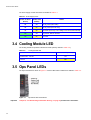
3.4 Cooling Module LED .................................................................................................................
3.5 Ops Panel LEDs ........................................................................................................................
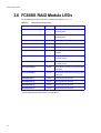
3.6 FC60SS RAID Module LEDs ....................................................................................................
3.7 Disk I/O Module LEDs ...............................................................................................................
3.8 Starting the Drives .....................................................................................................................
3.8.1
Disk Drive LEDs ...............................................................................................................
41
41
41
41
42
42
44
45
45
45
Contents
3.9 Starting StorView ....................................................................................................................... 45
3.10 Power Down .............................................................................................................................. 46
4
Troubleshooting and Problem Solving .......................................................................................
4.1 Overview ...................................................................................................................................
4.1.1
Initial Start-up Problems ...................................................................................................
4.2 Status Indicators (LEDs) ...........................................................................................................
4.2.1
Power Supply Module LEDs .............................................................................................
4.2.2
Cooling Module LED ........................................................................................................
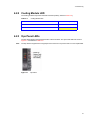
4.2.3
Ops Panel LEDs ...............................................................................................................
4.2.4
FC60SS RAID Module LEDs ............................................................................................
4.2.5
Disk I/O Module LEDs ......................................................................................................
4.2.6
Drive Carrier LEDs ...........................................................................................................
4.3 Audible Alarm ............................................................................................................................
4.3.1
Audible Alarm Mute ..........................................................................................................
4.4 Drive Carrier Module Faults ......................................................................................................
4.4.1
Auto Start Failure .............................................................................................................
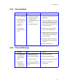
4.5 Troubleshooting .........................................................................................................................
4.5.1
System Faults ...................................................................................................................
4.5.2
Power Supply Faults ........................................................................................................
4.5.3
Thermal Control ................................................................................................................
4.5.4
Thermal Alarm ..................................................................................................................
4.5.5
Thermal Warnings ............................................................................................................
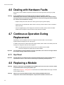
4.6 Dealing with Hardware Faults ...................................................................................................
4.7 Continuous Operation During Replacement ..............................................................................
4.7.1
Ops Panel .........................................................................................................................
4.8 Replacing a Module ...................................................................................................................
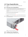
4.9 Power Supply Modules ..............................................................................................................
4.9.1
Removing a Power Supply Module ..................................................................................
4.9.2
Installing a Power Supply Module ....................................................................................
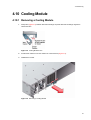
4.10 Cooling Module .........................................................................................................................
4.10.1 Removing a Cooling Module ............................................................................................
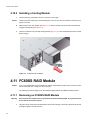
4.10.2 Installing a Cooling Module ..............................................................................................
4.11 FC60SS RAID Module ..............................................................................................................
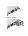
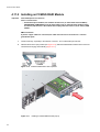
4.11.1 Removing an FC60SS RAID Module ...............................................................................
4.11.2 Installing an FC60SS RAID Module .................................................................................
4.12 Battery Module ..........................................................................................................................
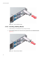
4.12.1 Removing a Battery Module .............................................................................................
4.12.2 Installing a Battery Module ...............................................................................................
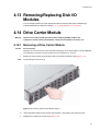
4.13 Removing/Replacing Disk I/O Modules .....................................................................................
4.14 Drive Carrier Module .................................................................................................................
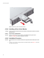
4.14.1 Removing a Drive Carrier Module ....................................................................................
4.14.2 Installing a Drive Carrier Module ......................................................................................
4.14.3 Installation Procedure .......................................................................................................
4.14.4 Dummy Drive Carrier Module Removal/Replacement .....................................................
4.15 Spare Parts and Ancillary Items ...............................................................................................
47
47
47
48
48
49
49
51
51
52
52
52
52
53
53
53
54
54
55
55
56
56
56
56
57
57
57
59
59
60
60
60
62
63
63
64
65
65
65
66
66
68
68
Index ..................................................................................................................................................... 69
v
Enclosure User Guide
Intentionally Blank
vi
Preface
Preface
What is in this guide
This user guide gives you step-by-step instructions on how to install, configure and connect an FC60SS
SAS Enclosure Platform to your host computer system and how to use and maintain the
system. Information is also provided on achieving FC60SS RAID enclosure expansion by
connecting FC60SS expansion enclosures.
Who should use this guide
This user guide assumes that you have a working knowledge of the SAS -SATA environment into which
you are installing your FC60SS Enclosure Platform. If you do not have these skills, or are not
confident with the instructions in this guide, do not proceed with the installation.
International Standards
The FC60SS and FC60SS SAS Enclosure Platforms comply with the requirements
of the following agencies and standards:
• CE to EN60950
• UL
• cUL
Potential for Radio Frequency
Interference
USA Federal Communications Commission (FCC)
Note
This equipment has been tested and found to comply with the limits for a class A digital device, pursuant
to Part 15 of the FCC rules. These limits are designed to provide reasonable protection against harmful
interference when the equipment is operated in a commercial environment. This equipment generates,
uses and can radiate radio frequency energy and, if not installed and used in accordance with the
instruction manual, may cause harmful interference to radio communications. Operation of this
equipment in a residential area is likely to cause harmful interference in which case the user will be
required to correct the interference at his own expense.
Properly shielded and grounded cables and connectors must be used in order to meet FCC emission
limits. The supplier is not responsible for any radio or television interference caused by using other than
recommended cables and connectors or by unauthorized changes or modifications to this equipment.
Unauthorized changes or modifications could void the user’s authority to operate the equipment.
This device complies with Part 15 of the FCC Rules. Operation is subject to the following two conditions:
(1) this device may not cause harmful interference, and (2) this device must accept any interference
received, including interference that may cause undesired operation.
vii
Enclosure User Guide
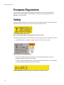
European Regulations
This equipment complies with European Regulations EN 55022 Class A: Limits and Methods of
Measurement of Radio Disturbance Characteristics of Information Technology Equipments and
EN50082-1: Generic Immunity.
Safety
All plug-in modules are part of the fire enclosure and must only be removed when a replacement can be
immediately added. The system must not be run without all modules in place.
.
Drive Carrier Module Caution Label:
Do not operate with modules missing; Spin down time 30 seconds
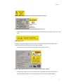
Permanently unplug the unit if you think that it has become damaged in any way and before you move it
• A FC60SS enclosure can weigh up to 32kg (70.4lb). Do not try to lift it by yourself.
Chassis Warning Label: Weight Hazard
• Do not lift a FC60SS enclosure by the handles on the Power Supply modules, they are not
designed to support the weight of the enclosure.
• In order to comply with applicable safety, emission and thermal requirements no covers should be
removed and all bays must be fitted with plug-in modules.
FC60SS RAID Module Caution Label: Do not operate with modules missing
viii
Preface
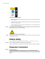
Battery Module Caution Label: Do not operate with modules missing
Fan Module Caution Label: Do not operate with modules missing
• FC60SS-1220 enclosures must only be operated from a power supply input voltage range of 100 - 240
VAC.
PSU Ratings Label
The plugs on the power supply cord are used as the main disconnect device. Ensure that the socket
outlets are located near the equipment and are easily accessible.
• The equipment must be operated with two working Power Supply modules.
Power Supply Module Caution Label: Do not operate with modules missing
• A faulty Power Supply module must be replaced with a fully operational module within 24 hours.
• When powered by multiple AC sources, disconnect all supply power for complete isolation.
ix
Enclosure User Guide
PSU Warning Label: Power Hazards
• The power connection should always be disconnected prior to removal of the Power Supply module
from the enclosure.
• A safe electrical earth connection must be provided to the power cords. Check the grounding of the
enclosure before applying power.
• Provide a suitable power source with electrical overload protection to meet the requirements laid
down in the technical specification.
Warning
Do not remove covers from the Power Supply module. Danger of electric shock inside. Return the
Power Supply module to your supplier for repair.
PSU Safety Label: Electric Shock Hazard Inside
Caution
If this equipment is used in a manner not specified by the manufacturer, the protection provided by the
equipment may be impaired.
Battery Safety
The Li-Ion battery is user replaceable, please refer to section 4.12, ”Battery Module”, on page 63.
Warning
There is a danger of explosion if the battery is incorrectly replaced.
Dispose of used batteries in accordance with the manufacturer’s instructions and national regulations.
Expansion Connectors
Important
x
Class 1 Laser Product:
If fitted with Optical modules, the modules must be a UL (or other North American NRTL)
RECOGNISED COMPONENT and must be approved by TUV (or other European product safety
test house) and the laser in the module must comply with Laser Class 1, US 21 CFR (J) and EN
60825-1.
Preface
EMC Precautions
If passive copper cables are connected, the cable must not have a connection to a common ground/earth
point.
Rack System Precautions
The following safety requirements must be considered when the unit is mounted in a rack.
• The rack design should incorporate stabilizing features suitable to prevent the rack from tipping or
being pushed over during installation or in normal use.
• When loading a rack with the units, fill the rack from the bottom up and empty from the top down.
• System must be operated with low pressure rear exhaust installation (Back pressure created by rack
doors and obstacles not to exceed 5 pascals [0.5mm Water gauge])
• The rack design should take into consideration the maximum operating ambient temperature for the
unit, which is 40°C when two Power Supply modules are fitted.
• The rack should have a safe electrical distribution system. It must provide overcurrent protection for
the unit and must not be overloaded by the total number of units installed in the rack. Consideration
of the units nameplate rating should be used when addressing these concerns.
• The electrical distribution system must provide a reliable earth for each unit and the rack.
• Each power supply in each unit has an earth leakage current of <1.5mA maximum at 60Hz, 264 V
AC per PSU. The design of the electrical distribution system must take into consideration the total
earth leakage current from all the power supplies in all the units. The rack will require labelling with
"HIGH LEAKAGE CURRENT. Earth connection essential before connecting supply".
• The rack when configured with the units must meet the safety requirements of UL 60950 and IEC
60950.
ESD Precautions
Caution
It is recommended that you fit and check a suitable anti-static wrist or ankle strap and observe all
conventional ESD precautions when handling FC60SS-1220 plug-in modules and components. Avoid contact
with backplane components and module connectors, etc.
Recycling of Waste Electrical and
Electronic Equipment (WEEE)
At the end of the products life, all scrap/ waste electrical and electronic equipment should be recycled in
accordance with National regulations applicable to the handling of hazardous/ toxic electrical and
electronic waste materials.
xi
Enclosure User Guide
Please contact Cutting Edge for a copy of the Recycling Procedures applicable to your product.
Important
Observe all applicable safety precautions, e.g. weight restrictions, handling batteries and lasers
etc., detailed in the preceding paragraphs when dismantling and disposing of this equipment
Data Security
• Power down your host computer and all attached peripheral devices before beginning installation.
• Each enclosure contains up to 12 removable disk drive modules. Disk units are fragile. Handle them
with care, and keep them away from strong magnetic fields.
• All the supplied plug-in modules, dummy carriers and blank modules must be in place for the air to
flow correctly around the enclosure and also to complete the internal circuitry.
• If the subsystem is used with plug-in modules, dummy carriers or blank modules missing for more
than a few minutes, the enclosure can overheat, causing power failure and data loss. Such use may
also invalidate the warranty.
• If you remove any drive module, you may lose data.
– If you remove a drive module, replace it immediately. If it is faulty, replace it with a drive module
of the same type and capacity
• Ensure that all disk drives are removed from the enclosure before attempting to manhandle or move
the rack installation.
• Do not abandon your backup routines. No system is completely infallible.
Special Tools and Equipment
There are no special tools required but in order to complete the assembly of some configurations you may
need the following:
• Security keys (one of these should be included with your FC60SS enclosure for use with the drive
locks).
xii
Preface
Page Left Intentionally Blank
xiii
Enclosure User Guide
xiv
Introduction
Chapter 1
Introduction
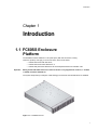
1.1 FC60SS Enclosure
Platform
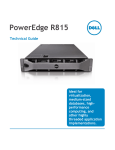
The FC60SS Enclosure Platform is a 2U (rack space) disk drive enclosure, housing
twelve low profile (1 inch high), 3.5 inch form factor, which can be either:
– 3.0Gb/s direct dock SAS disk drives,
– 3.0Gb/s direct dock SATA disk drives, or
– 3.0Gb/s dual path SATA disk drives via an active/passive SATA mux transition card.
Important
Mixing of SAS and SATA drives in the same enclosure is only supported in columns, i.e. Column
1 all SAS, Column 2 all SATA etc.
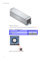
The system will provide up to 6Tbytes of data storage per enclosure when 500Gb drives are installed.
Figure 1–1 FC60SS Enclosure
1
Enclosure User Guide
1.2 FC60SS-XPN Expansion
Enclosure
FC60SS RAID enclosure expansion is achieved by connecting FC60SS-XPN expansion
enclosures. Multiple enclosures are connected together using SAS patch cables, up to a total of five
enclosures. Please refer to section 2.9, ”Enclosures Expansion”, on page 32.
1.3 The Enclosure Core Product
The FC60SS design concept is based on an enclosure subsystem together with a set of plug-in modules.
The FC60SS SAS Enclosure Platform as supplied comprises:
• Chassis and Backplane with integral (front panel mounted) Operator’s Panel (See Figure 1–6).
• Up to 12 Drive Carrier Modules (See Figure 1–16), containing either:
– 3.0Gb/s direct dock SAS disk drives,
– 3.0Gb/s direct dock SATA disk drives, or
– 3.0Gb/s dual path SATA disk drives via an active/passive SATA mux transition card.
Note: Dummy Carriers modules must be fitted in all unused drive bays to maintain airflow, please
refer to section 1.4.7 on page 14.
• Two plug-in Power Supply Modules,100-240V AC, 350W (see Figure 1–7)
• One plug-in Cooling Fan Module (see Figure 1–8)
• Two plug-in FC60SS RAID Modules. (See Figure 1–10), incorporating a FC60SS RAID Controller
and a Storview Management Module.
Note: If only one FC60SS RAID module is installed then a Blank module must be fitted in the
unused slot. The module should be fitted in Slot 0 and the blank in Slot 1 (where Slot 0 is the
lower slot and Slot 1 the upper, see Figure 1–3).
The FC60SS-XPN Expansion enclosure platform as supplied comprises
• Chassis and Backplane with integral (front panel mounted) Operator’s Panel (See Figure 1–6).
• Up to 12 Drive Carrier Modules (See Figure 1–16), containing either:
– 3.0Gb/s direct dock SAS disk drives,
– 3.0Gb/s direct dock SATA disk drives, or
– 3.0Gb/s dual path SATA disk drives via an active/passive SATA mux transition card.
Note: Dummy Carriers modules must be fitted in all unused drive bays to maintain airflow, please
refer to section 1.4.7 on page 14.
• Two plug-in Power Supply Modules,100-240V AC, 350W (see Figure 1–7)
• One plug-in Cooling Fan Module (see Figure 1–8)
2
Introduction
• Two Disk I/O Modules (see Figure 1–14)
Note: If only one Disk I/O module is installed then a Blank module must be fitted in the unused
slot. The module should be fitted in Slot 0 and the blank in Slot 1 (Figure 1–5).
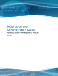
1.3.1 Enclosure Chassis
The chassis consists of a sheet metal enclosure assembly containing a Backplane printed circuit board
(PCB) and module runner system.
• The chassis front panel incorporates an integral Operator’s (Ops) Panel.
• The Backplane PCB provides logic level signal and low voltage power distribution paths.
• Figure 1–2 and Figure 1–3 show front and rear views of a populated FC60SS chassis
respectively.
• Figure 1–4 and Figure 1–5 show front and rear views of a populated FC60SS chassis
respectively.
• The chassis is fitted with 19 inch Rack mounting features which enable it to be fitted to standard 19
inch racks and uses 2 EIA units of rack space (i.e. 3.5” high).
The chassis assembly contains 12 drive bays at the front, each of which accommodates the appropriate
plug-in drive carrier module. The 12 drive bays are arranged in 3 rows of 4 drives. At the rear, the chassis
assembly contains five plug-in module bays to house two Power Supply modules, a Cooling Fan module
and two FC60SS RAID modules (which are fitted horizontally), as shown in Figure 1–3
Note
A drive bay is defined as the space required to house a single 1.0" high 3.5 inch disk drive in its carrier
module, shown in Figure 1–2.
.
Figure 1–2
FC60SS Enclosure (Front)
Figure 1–3
FC60SS Enclosure (Rear)
3
Enclosure User Guide
.
Figure 1–4
FC60SS-XPN Enclosure (Front)
Figure 1–5
FC60SS-XPN Enclosure (Rear)
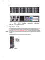
1.3.2 Operator’s Panel
The FC60SS enclosure front panel incorporates an Operator’s (Ops) Panel with four LEDs, see Figure
1–6. The Ops Panel provides the user with a high level indication of the operation of the Enclosure.
Please refer to Table 3–3, ”Ops Panel LED States”, on page 43 for details of the LED status conditions.
Caution
The Ops Panel is an integral part of the enclosure assembly and can only be replaced with a replacement
enclosure.
Enclosure replacement should only be performed by trained personnel.
Figure 1–6
4
Ops Panel
Introduction
1.3.3 Alarms
1.3.3.1
Visible Alarms
The functional modules have associated status LEDs. The Ops Panel shows a consolidated status for all
modules.
LEDs show constant Green or Blue for good or positive indication. Constant or flashing Amber LEDs
indicate there is a fault present within that module.
Table 1–1 Status LEDs
LED
State
Description
Power On
Constant Green:
Good or positive indication
System Fault
Constant Amber: fault present Indicates a problem with a Power Supply, Cooling
or RAID module. Refer to individual modules that
contain individual fault LEDs, see Table 4–1 on
page 48, Table 4–2 on page 49 and Table 4–4 on
page 51
Logical Fault
Constant Amber: fault present Indicates failure of a drive module. The module
failing will be indicated by the Fault LED, see Table
4–6 on page 52
Box Identity
Constant Blue: enclosure
identity
The user can illuminate this via the Management
interfaces to indicate which enclosure requires
service actions to be performed on it.
Please refer to Table 3–3 on page 43 for a description of the Ops Panel LED states.
1.3.3.2
Audible Alarms
FC60SS enclosures include an Audible Alarm which indicates when a fault state is present. The following
conditions will activate the Audible Alarm:
•
•
•
•
•
•
•
•
•
Fan Fault
Voltage out of range
Over temperature
Thermal overrun
System fault
Logical Fault
PSU Fault
Removal of 1 PSU
Invalid cabling
When the Audible Alarm sounds, it may be muted by pressing the Alarm Mute push-button which is
incorporated in the enclosure front panel. Please refer to section 4.3.1 on page 52 for more information
on this function.
5
Enclosure User Guide
1.4 The Plug-in Modules
An FC60SS enclosure requires the following modules for normal operation:
• 2 x 350W AC Power Supply modules
• 1 x Cooling module
• FC60SS: 1 or 2 x FC60SS RAID modules
• FC60SS: 2 x Disk I/O modules
• Up to 12 Drive Carrier modules.
• Dummy Carrier modules, as required.
Note: No bays should be left completely empty, Dummy Carrier modules and/or blank modules
must be fitted in all unused bays.
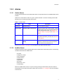
1.4.1 AC Power Supply Module
Two 100-240 V AC 350W Power Supply modules (Figure 1–7) are supplied mounted in the rear of the
enclosure as part of the enclosure core product.
Figure 1–7
.
AC Power Supply Module
PSU voltage operating ranges are nominally 115V or 230V AC, selected automatically.
.
Two LEDs mounted on the rear panel of the Power Supply module (see Figure 1–7) indicate the status
of the module:
6
Introduction
Table 1–2
1.4.1.1
Power Supply LEDs
Power On & OK
(Green)
Module Fault
(Amber)
Status
Off
Off
No AC power (either PSU)
Off
On
No AC power (this PSU only)
Off
On
PSU Fault (over temp, over voltage, over current, PSU fan fail)
On
Off
AC present, PSU on and OK
On
On
Fan Fault
Multiple Power Supply Modules
The FC60SS enclosure must always be operated with two Power Supply modules fitted. The two Power
Supply modules operate together so that if one fails the other maintains the power supply and cooling
while you replace the faulty unit.
Module replacement should only take a few minutes to perform but must be completed within 10 minutes
from removal of the failed module.
1.4.2 Cooling Module
The Cooling Module (Figure 1–8) provides system cooling, thermal monitoring and control functions.
System airflow is from front to back of the enclosure:
• Cooling air passes over drives and through the midplane to a central plenum.
• The cooling module pulls air from the plenum and from the RAID modules.
• The PSUs pull cooling air from the plenum at the rear of the enclosure.
Note
The system must be operated with low pressure rear exhaust installation (back pressure created by rack
doors and obstacles not to exceed 5 pascals {0.5mm water gauge})
7
Enclosure User Guide
Figure 1–8 Cooling Module
The Cooling module incorporates an amber Cooling Module Fault LED, defined in Table 1–3.
Table 1–3
Cooling Module Fault LED
Status
Enclosure On - Fan OK
Off
Fan Fail
On
Figure 1–9 Cooling Module Fault LED Location
8
Module Fault (Amber)
Introduction
1.4.3 FC60SS RAID Module
One or two FC60SS RAID modules (according to customer configuration) are supplied mounted in the
rear of the enclosure as part of the FC60SS enclosure core product.
The plug-in FC60SS RAID modules have been designed for integration into a FC60SS enclosure,
providing external FC cable interfacing with the host computer system.
The Backplane incorporates connection to each of the SAS ports within the FC60SS RAID modules.
The FC60SS RAID module internal processor monitors error conditions on each disk drive port.
Processors housed on the FC60SS RAID modules provide enclosure management interfacing to devices
on the Backplane, PSU, FC60SS RAID module and Ops Panel, to monitor internal functions.When the
enclosure is supplied in dual controller configuration these processors operate in a dual active
configuration to allow failover.
The module incorporates LED indicators, shown in Figure 1–11. please refer to Table 3–4, ”FC60SS RAID
Module LEDs”, on page 44 for details of the LED status conditions.
The FC60SS RAID module has the following external ports.
• Two external (Host) ports that allow for fitting of Small Form Factor Pluggable (SFP) modules, with
auto-bypass at the output. Either or both of these SFP ports can be used to provide connection to
the Host controllers. Each host port operates at 4Gb/s, giving an effective speed of 8Gb/s; these
ports are also backwards compatible with 2Gb/s hosts.
• An SAS expansion port provides for expansion up to a maximum of four FC60SS-XPN
enclosures via an SFF-8470 connector.
• An RJ45 10/100BaseT Ethernet port allows the controller to be connected to a network to enable
out-of -band management and monitoring using the Embedded Storview GUI software.
Note: Screened twisted pair Ethernet cable must only be used for connection to the Ethernet port.
• There is also an RS232 socket which provides an alternative user interface to the RJ45 connector.
Caution
Although the RS232 port is similar in appearance to a USB port it requires a special cable and users
should NOT attach a USB cable to it.
9
Enclosure User Guide
Figure 1–10
FC60SS RAID Module
Figure 1–11
FC60SS Module Front Panel
The recommended configurations are shown in sections 2.7 on page 27 and 2.9 on page 32.
1.4.3.1
StorView ® Management Software
The StorView ® Storage Management software which is embedded in the FC60SS RAID Module is a fullfeatured graphical HTML-based software suite designed to configure, manage and monitor the FC60SS
RAID Module Storage Solution. The module is supplied configured with a base IP address to
10
Introduction
to allow the user to connect to it. Please refer to section 3.9, ”Starting StorView”, on page 45 for further
information.
1.4.4 Battery Module
The FC60SS RAID module assembly includes a removable Battery module, located as shown in Figure 1–
10. The battery module contains a replaceable Li-Ion battery pack, see Figure 1–12. The battery pack
provides protection of the cache contents if the AC power fails. The time protected is available via the
Management Interface and is dependent on the amount of cache in the system.
Please refer to section 4.12 on page 63 for removal/replacement procedures.
Figure 1–12 Battery Module
.
Figure 1–13
Enclosure Rear View
11
Enclosure User Guide
1.4.5 Disk I/O Module
FC60SS-XPN storage expansion subsystems include an enclosure with rear facing bays which
house two Disk I/O modules, shown in Figure 1–14.
The plug-in Disk I/O modules have been designed for integration into FC60SS-XPN storage
subsystems, utilizing SAS interconnections with the host computer system.
Processors housed on the Disk I/O modules provide enclosure management and interface to devices on
the Backplane, PSU, Disk I/O module and Ops Panel, to monitor internal functions. These processors
operate in a master slave configuration to allow failover.
The enclosure may be configured with either 1 or 2 modules. If only 1 Disk I/O module is fitted a blank
module should be fitted in the unused bay.The module incorporates LED indicators, shown in Table 1–4:
Table 1–4
Disk I/O Module LEDs
LED Functions
Host 0 & Host 1
(Green)
Expansion
(Green)
Figure 1–14
12
State
Description
ON
Flashing
OFF
Ready
Active
Not Ready
ON
Flashing
OFF
Ready
Active
Not Ready
Disk I/O Module
Introduction
Note
Figure 1–15 Disk I/O Module Front Panel
The EXP’N port connects to the Host port on the next FC60SS-XPN enclosure in a multiple enclosure
configuration, please refer to section 2.9 on page 32 for further information on enclosure expansion.
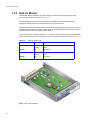
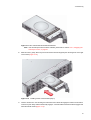
1.4.6 Drive Carrier Module
The Drive Carrier Module comprises a hard disk mounted in a carrier. Each drive bay will house a single
Low Profile 1.0 inch high, 3.5 inch form factor disk drive in its carrier.The carrier has mounting locations
for SAS or SATA drives.
The front cap also supports an ergonomic handle which provides the following functions:
• Camming of carrier into and out of drive bays.
• Positive 'spring loading' of the drive/backplane connector.
• An anti-tamper lock operated by a torx socket type key.
Figure 1–16 Drive Carrier Module
1.4.6.1
Drive Status Indicators
Each drive carrier incorporates two LEDs, an upper (Green) and lower (Amber). In normal operation the
green indicator will be ON and will flicker as the drive operates The amber indicator will only be ON if
there is a drive fault. If the green LED is OFF when the amber LED is ON, a power control circuit failure
is indicated.
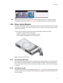
1.4.6.2
Anti-tamper Locks
Anti-tamper locks are fitted in the drive carrier handles (Figure 1–17) and are accessed through the small
cutout in the latch section of the handle.These are provided to disable the normal ‘pinch' latch action of
the carrier handle.
13
Enclosure User Guide
Figure 1–17
Anti-tamper Lock
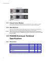
1.4.7 Dummy Carrier Modules
Dummy Carrier modules are provided for fitting in all unused drive bays. They are designed as integral
drive module front caps and must be fitted to all unused drive bays to maintain a balanced airflow.
1.4.8 Blank Modules
When only one FC60SS RAID module is installed, a Blank module must be fitted in the vacant RAID (I/O)
module slot at the rear of the enclosure to maintain airflow and ensure correct operation.
Warning
Operation of the Enclosure with ANY modules missing will disrupt the airflow and the drives will
not receive sufficient cooling. It is ESSENTIAL that all apertures are filled before operating the FC60SS
enclosure system.
1.5 FC60SS Enclosure Technical
Specifications
1.5.1 Dimensions
Enclosure
Height
Width across mounting flange
inches
mm
3.46
87.9
19
483
Width across body of enclosure
17.6
447
Depth from flange to rear of enclosure body
21.65
550
Depth from flange to maximum extremity of enclosure
(rear hold down)
22.72
577
Depth from flange to furthest extremity at front of unit
1.44
36.5
It is recommended that a rack with a depth of no less than 700mm (27.55 inches) is used with this product.
14
Introduction
1.5.2 Weight
Maximum Configuration
32kg (70.4lb)
Empty Enclosure
9kg (19.8lb)
1.5.3 AC Power (350W PSU)
1.5.4
Voltage Range
100--240 VAC Rated
Frequency
50/60 Hz
Inrush Current
<30A @ 230VAC
Power Factor
>0.98
Harmonics
Meets EN61000-3-2
Power Consumption
Power consumption of enclosure with 12x SAS drives running IO, powered by a single PSU (Power One
PSU) with extended power lead between PSU and IO Backplane and with two controllers installed at
IDLE and ACTIVE operation.
Voltage Rail
ACTIVE
IDLE
Average
Peak
Average
Peak
5V
11.51A
13.2A
13.53A
15.7A
12V
12.29A
15.1A
13.17A
20.1A
1.5.5 PSU Safety and EMC Compliance
Safety Compliance
UL 60950
IEC 60950
EN 60950
EMC Compliance
CFR47 Part 15B Class A
EN55022
EN55024
1.5.6 Power Cords
1
2
United States
Must be NRTL LISTED (National Recognized Test Laboratory, e.g. UL)
Cord type
SV or SVT, 18 AWG minimum, 3 conductor, 4.5 M max length.
Plug
NEMA 5-15P grounding-type attachment plug rated 120V 10A;
or
IEC 320 C14, 250V, 10A.
Socket
IEC 320, C-13, 250V, 10A.
Europe & Others
15
Enclosure User Guide
General requirements:-
Important
Cord type
Harmonized, H05-VVF-3G1.0
Socket
IEC 320, C-13, 250V, 10A.
The Plug and the complete power cord assembly must meet the standards appropriate to the
country, and must have safety approvals acceptable in that country.
1.5.7 Environment
Table 1–5
Ambient Temperature and Humidity
Temperature Range
Operational
Relative Humidity
Max. Wet Bulb
8% to 80%
23°C
5°C to 40°C
non-condensing
Non-Operational
1°C to +50°C
8% to 80%
27°C
non-condensing
Storage
1°C to +60°C
8% to 80%
29°C
non-condensing
Shipping
-40°C to +60°C
5% to 100%
29°C
non-precipitating
Airflow
System must be operated with low pressure rear exhaust installation
(Back pressure created by rack doors and obstacles not to exceed 5
pascals [0.5mm Water gauge])
Altitude, Operational
0 to 3045 m (0 to 10,000ft)
Altitude, Non-Operational
-305 to 12,192m (-1000 to 40,000ft)
Shock, Operational
Vertical axis 5g peak 1/2 sine, 10ms
Shock, Non-Operational
30g 10ms 1/2 sine
Vibration, Operational
0.21grms 5-500 Hz Random
Vibration, Non-Operational
1.04grms 2-200 Hz Random
Vibration, Relocation
0.3g 2-200 Hz sine
Acoustics
Sound Power Operating:
• Less than 58 dB LwA measured at 23°C.
Sound Pressure Operating:
• Less than 6.8 Bels LwA measured at 23°C.
Orientation & Mounting
To fit 800mm depth Racks compliant with IEC 297
• Rack Characteristics
Back pressure not exceeding 5 pascals (0.5mm water gauge)
Safety & Approvals
• EMC
16
19" Rack mount (2EIA Units)
• Rack Rails
CE, UL, cUL
EN55022 (CISPR - A), FCC A
Introduction
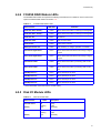
1.5.8 Interfaces
Drive support See drive carrier specification
Attachment
• 1 domain of 12 drives per FC60SS RAID module
• 2 Fibre Channel Host Ports (Arbitrated Loop, Point-Point & Fabric attachment
supported)
– 2 x SFP optical per FC60SS RAID module
• 1 SAS Expansion Port
– 1 X SFF
1.5.9 FC60SS RAID Module Specification
Speed
Mounting
• Host Ports: two 4Gb/sec Fibre Channel, also supporting 2Gb/sec and
1Gb/sec mode
• Drive Ports: 3Gb/s SAS, creates connections to a single domain of 12
drives
Rear, horizontal in Bay 4 (see Figure 1–3)
Connectors
Power Consumption
• 2 x SFP connectors for Host 0 and Host 1 Ports, to accommodate optical
interconnects (LC to LC cable), maximum length 500m
• 1 x 4xSAS Expansion connector (SFF)
• 1 x RJ45, 10/100BaseT Ethernet connection
• 1 x RS232 (factory use only)
40W
LED Functions
LED Functions
LED State
Definition
Controller Slot 0 Activity*
Amber
When ON the Controller is currently processing data
Controller Slot 1 Activity*
Amber
When ON the Controller is currently processing data
Controller OK
Green
Module OK
Controller Fault
Amber
Fault on this module
Cache Active
Amber
Active cache contents
Battery/Controller Fail
Amber
Fault in battery or charger operation of controller
Host 0 Port Signal Good
Green
When ON the LED denotes that incoming FC signal is
good
Host 1 Port Signal Good
Green
When ON the LED denotes that incoming FC signal is
good
Host 0 Port Traffic*
Amber
When ON the Controller is processing data on this
port
Host 1 Port Traffic*
Amber
When ON the Controller is processing data on this
port
17
Enclosure User Guide
SAS Expansion 1*
Green
When ON this port is active
SAS Expansion 2*
Green
When ON this port is active
SAS Expansion 3*
Green
When ON this port is active
SAS Expansion 4*
Green
When ON this port is active
* These LEDs blink on/off when there is module activity.
1.5.10 Drive Carrier Module Specification
Important
18
Operating FC60SS enclosures with non-approved drives may invalidate the warranty.
Please contact your supplier for details of approved drives.
Module Dimensions
• Height 1.06” (27.05mm(
• Width 4.19” (106.55mm)
• Depth 8.25” (209.55mm)
Weight
• 0.88kg (1.0” 36Gb drive)
Operating Temperature
5° C to 40° C (when installed in an FC60SS system enclosure with dual
Power Supply Modules)
Power Dissipation
18.5 Watts maximum
Getting Started
Chapter 2
Getting Started
2.1 Introduction
In this chapter, you are shown how to install your FC60SS enclosure into an industry standard 19 inch
rack cabinet and configure the enclosure sub-system.
Caution
When connecting up FC60SS enclosures, use only the power cords supplied or cords which match the
specification quoted in section 1.5.6.
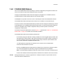
2.2 Planning Your Installation
Before you begin installation you should become familiar with the configuration requirements of your FC60SS
enclosure, detailed in Table 2–1. The correct positions of each of the optional plug-in modules are
shown in Figure 2–1. Please refer to sections 2.7 to 2.9 (page 27 to page 32) for details of FC60SS RAID
module configurations.
Table 2–1
Caution
Enclosure System Configuration
Module
Location
Drive Bays
ALL drive bays must be fitted with a drive carrier module or dummy drive
carrier module; no bays should be left completely empty.
Power Supply Modules
Two Power Supply modules must be fitted. Full power redundancy is
provided while a faulty module is replaced. Install the Power Supply modules
in LH rear Bays (Figure 2–1)
Cooling Module
Install in rear bay, as shown in Figure 2–1
FC60SS RAID Module
Two FC60SS RAID Modules (or 1 FC60SS RAID Module plus1 blank
module) can be fitted, according to required configuration. The modules are
Installed horizontally (one above the other) in the RH rear Bay (Figure 2–1).
Blank Modules or Dummy Carrier modules MUST be fitted to ALL unused bays, there will be inadequate
drive cooling if any are left open.
19
Enclosure User Guide
Figure 2–1
Module locations
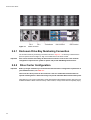
2.2.1 Enclosure Drive Bay Numbering Convention
The enclosure drive bay numbering convention is shown in Figure 2–1. A drive bay is defined as the
space required to house a single 1.0" high 3.5 inch disk drive in its carrier module.
Important
2.2.2
Important
Drive carrier modules must always be fitted in drive locations 1 and 12. This is the minimum
configuration required for the system to operate and provide SES Management Services.
Drive Carrier Configuration
Before you begin installation you should become familiar with the configuration requirements of
your FC60SS enclosure, see Table 2–1.
There must be a drive present in drive locations 1 and 12 to enable SES Communications to
operate. Installing drives in both of these bays will provide redundant SES communication paths.
When planning your system configuration, please remember that all FC60SS enclosure drive bays must
be filled with either a Drive Carrier or Dummy Carrier module, no bays should be left completely empty.
20
Getting Started
2.3 Enclosure Installation Procedures
Caution
An FC60SS enclosure with all component parts installed is too heavy for a single person to safely install
alone into a Rack cabinet. The following procedures describe the installation of an FC60SS
enclosure and highlights any critical co-requisite requirements and good handling practices which we
encourage you to follow so as to ensure that a successful installation is achieved in the easiest manner.
Warning
Ensure that you have fitted and checked a suitable anti-static wrist or ankle strap and observe all
conventional ESD precautions when handling FC60SS modules and components.
Avoid contact with Backplane components and module connectors, etc.
2.3.1 Preparation of Site and Host Server
Before you begin, make sure that the site where you intend to set up and use your FC60SS storage
system has the following:
• Standard AC power from an independent source or a rack Power Distribution Unit with a UPS
(universal power supply).
• A host computer with a standard Fibre Channel HBA (host bus adaptor) with the latest BIOS and
drivers. Follow the instructions provided with your HBA and install the HBA and its driver software,
if necessary.
Note: The FC60SS system supports most of the widely used operating systems, however
deployment on Microsoft Windows requires the.inf driver file which is found on the Software
and Manuals CD.
(For Windows Servers: Insert the Software and Manuals CD and install the.inf file.)
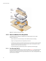
2.3.2 Unpacking the Enclosure System
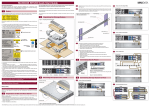
The package contents and unpacking procedure are outlined in Figure 2–2.
The Accessory Box contains the AC power cord(s), a serial communication cord and the Software and
Manuals CD. The Accessory Box Insert contains the adjustable rail slides and hardware parts to rack
mount the enclosure.
21
Enclosure User Guide
Figure 2–2 Unpacking the Enclosure System
2.3.3 Rack Installation Pre-Requisites
The FC60SS enclosure is designed for installation into an industry standard 19 inch cabinet
capable of holding the unit.
• Minimum depth 700 mm from front flange to rear metalwork (excludes rear cabling).
• Weight: up to 32kg dependent upon configuration per enclosure.
• A minimum gap of 25mm (1inch) clearance between the rack cover and front of drawer; and 50mm
(2 inches) rear clearance between rear of drawer and rear of rack is recommended in order to
maintain the correct air flow around the enclosure.
• The rack should present a maximum back pressure of 5 pascals (0.5mm water gauge).
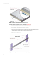
2.3.3.1
Rack Mounting Rail Kit
A set of mounting rails is available for use in 19 inch rack cabinets (Figure 2–3). These rails have been
designed and tested to handle the maximum enclosure weight and to ensure that multiple FC60SS
enclosures may be installed without loss of space within the rack. Use of other mounting hardware may
cause some loss of rack space.
22
Getting Started
The rack mounting rail kit also incorporates a rear hold down mechanism to ensure shock and vibration
immunity.
Please contact your supplier to ensure suitable mount rails are available for the rack you are using.
Latch
(both sides)
(Left hand assembly shown)
Figure 2–3
Rack Mounting Rail Kit
2.3.4 Rack Installation Procedure
Please refer to the detail drawings supplied with the rack mounting rail kit for further information
2.3.4.1
Parts Check List
Rack Mounting Rail Kit
2.3.4.2
Installation Procedure
1
Attache left and right chassis slides to the enclosure sides using 8 M3x4 button head screws (see Figure
2–4).
2
assemble the left and right chassis latches using the special chassis latch screws. Ensure that the latch
is orientated as shown in Figure 2–4, with the spring arm located against its stop.On the right hand this
is at the top, on the left it is at the bottom.
23
Enclosure User Guide
Figure 2–4 Securing Chassis Slides to Enclosure (steps 1 & 2)
3
Assemble to brackets (not handed) to rack as follows (refer to Figure 2–5):
a Locate the location pin at the rear of the rail into the rear rail post.
b Extend the rail to fit between the front and rear rack posts.
c Attach to both front and rear of the rack using the washers and screws supplied The screws
should be left loose enough to allow for sideways movement of the rail.
d Tighten the two clamping screws.
Figure 2–5 Securing Brackets to Rack - left hand assembly (step 3)
24
Getting Started
4
Mount the enclosure in the rack as follows (refer to Figure 2–6):
a Lift the enclosure and align it with the rack rails.
b Carefully insert the chassis slides into the rack rails and push fully home.
c Tighten the rear screws.
d Withdraw the enclosure until it reaches the hard stops (approximately 400mm).
e Return the enclosure to the fully home position and attach to the rack using the captive fasteners
on the front flanges.
Figure 2–6 Mounting the Enclosure into a Rack (step 4)
2.3.5 Chassis Installation
2.3.5.1
Parts Check List
• Chassis (complete with Backplane, Ops Panel and all plug-in modules installed).
• Rack mounting thumbscrews (4 off).
2.3.5.2
Procedure
1
Fit the Rack Mounting Rail Kit in accordance with the mounting kit Installation procedure.
2
Check chassis for damage.
3
Slide the chassis assembly onto the rack rails until the front flanges engage on the rack. Ensure the
chassis is centrally located.
25
Enclosure User Guide
4
If in doubt about correct orientation, the Operator’s Panel should be on the left hand side of the enclosure.
5
Tighten the two mounting thumbscrews present on each chassis flange.
2.4 Module Installation
The FC60SS enclosure is supplied fully populated with all plug-in modules installed. For
information on removal/replacement of plug-in modules, please refer to Chapter 4. , ”Troubleshooting
and Problem Solving”, on page 47
2.5 Management Interfaces
The following management interfaces are provided and used to configure, manage and monitor the
FC60SS RAID Module Storage Solution.
2.5.1 StorView ® Storage Management Software
StorView ® Storage Management software is a full-featured graphical HTML-based software suite
designed to configure, manage and monitor the FC60SS RAID Module Storage Solution.
StorView provides the centralized local and remote management tool to control primary storage assets
vital to ensuring maximum data reliability, network up-time, and system serviceability. It also allows you
to manage and monitor the storage system from a host running StorView locally and from a web browser
across the intranet or internet.
StorView comprises the StorView Server which runs as a background service and is responsible for
managing the installed modules.
The StorView Server discovers system storage devices, manages and distributes message logs, and
communicates with other StorView Servers installed on the same local and external subnet networks.
A GUI provides the interface in an HTML-based front end which is accessed using a web browser.
The software incorporates a web server, Apache 2.0, that provides the interface between the StorView
Server and GUI. During installation the web server is automatically configured.
Please refer to the following documents:
• StorView Storage Manager Software Installation Guide
• StorView Storage Manager Software RAID Module User Guide
2.5.2 RAID Configuration Utility (Menu-based)
The FC60SS RAID module firmware based programs are accessed through a VT-100 terminal using a
menu-based RAID Configuration Utility interface.
Please refer to the following document:
26
Getting Started
• Menu-based RAID Configuration Utility User Guide .
2.5.3 RAID Configuration Utility (Text-based)
The FC60SS RAID module firmware based programs are accessed through a VT-100 terminal using a
text-based RAID Configuration Utility interface.
Please refer to the following document:
• Text-based RAID Configuration Utility User Guide
2.6 Enclosure Configuration
FC60SS enclosures are configured with one internal domain of 12 drives per FC60SS RAID
module.
2.7 Fibre Channel Interface
The FC60SS RAID module provides two Fibre Channel SFP interface connections.
The FC60SS RAID module provides bi-directional connection between the Fibre Channel host side
interface and the drives.The drives will not be presented to the Host until they are configured and mapped
by the controller.
Note
There are no external terminators required with Fibre Channel architecture and any drive may be hot
plugged during operation.
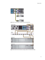
Each FC60SS RAID module can be connected to up to 2 independent Host Bus Adaptors or switch ports.
Some typical configurations utilizing two FC60SS RAID modules and either one or two HBAs are shown
in Figure 2–7 to Figure 2–13 inclusive:
Important
Optical modules must be UL (or other North American NRTL) RECOGNISED COMPONENT and the
laser in the module must comply with Laser Class 1, US 21 CFR (J) and EN 60825-1.
Please contact your supplier for a list of qualified optical SFP components.
27
Enclosure User Guide
Figure 2–7 Single Host Dual Controller Connections
Figure 2–8
28
Dual Host Dual Controller Connections
Getting Started
Figure 2–9 Dual Host Dual Controller Connections (Single HBA)
Figure 2–10 Dual Host Dual Controller and Single Switch Connections (Dual HBA)
29
Enclosure User Guide
Figure 2–11 Dual Host Dual Controller and Dual Switch Connections
Figure 2–12 Single Host Single Controller Connections
30
Getting Started
Figure 2–13 Dual Host Single Controller Connections
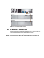
2.8 Ethernet Connection
An RJ45 10/100BaseT Ethernet port allows the controller to be connected to a network to enable out-of
-band management and monitoring using the Embedded Storview GUI software.
Ensure that the PC is connected either directly or via a switched LAN to the Ethernet.
Important
Only screened twisted pair Ethernet cable must be used for connection to the Ethernet port.
31
Enclosure User Guide
2.9 Enclosures Expansion
Additional expansion enclosures, e.g.FC60SS-XPN enclosures, can be connected to a
FC60SS enclosure. Multiple enclosures are connected together using SAS patch cables, up to a
maximum of 5 enclosures, a typical configuration is shown in Figure 2–14.
Figure 2–14 FC60SS Enclosure Expansion Configuration
32
Getting Started
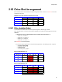
2.10 Drive Slot Arrangement
Each enclosure has 12 drives which are referenced by their location as shown in Table 2–2. Drives are
numbered column/row.
Table 2–2 Drive Slot Arrangement: Enclosure Front View
Column/row
1/#
2/#
3/#
4/#
#/1
Drive 1
Drive 2
Drive 3
Drive 4
#/2
Drive 5
Drive 6
Drive 7
Drive 8
#/3
Drive 9
Drive 10
Drive 11
Drive 12
2.10.1 Drive Location Rules
The FC60SS and FC60SS-XPN enclosure systems support two different types of disk
drive, SAS and SATA. In order to allow optimal configurations to be built, the following rules should be
observed:
1 Different drive types (i.e.SAS and SATA) cannot be mixed in the same column, i.e.
– Slots 1, 5, 9 = column 1
– Slots 2, 6, 10 = column 2
– Slots 3,7,11 = column 3
– Slots 4, 8, 12 = column 4
(see Table 2–2 for slot arrangement).
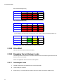
2 To achieve optimum performance drives should be populated in the following location sequence
– slots 2, 6 and 10 initially,
– followed by slots 3, 7, 11
– then slots 1, 5, 9
– and finally slots 4, 8, 12, i.e.
Drive Location Sequence (1)
Column/row
1/#
2/#
3/#
4/#
#/1
-
2
-
-
#/2
-
6
-
-
#/3
-
10
-
-
Drive Location Sequence (2)
Column/row
1/#
2/#
3/#
4/#
#/1
-
2
3
-
#/2
-
6
7
-
#/3
-
10
11
-
33
Enclosure User Guide
Drive Location Sequence (3)
Column/row
1/#
2/#
3/#
4/#
#/1
1
2
3
-
#/2
5
6
7
-
#/3
9
10
11
-
Drive Location Sequence (4)
Column/row
1/#
2/#
3/#
4/#
#/1
1
2
3
4
#/2
5
6
7
8
#/3
9
10
11
12
3 If a change in drive technology is required then a new column of drives should be populated, e.g.
Column/row
1/#
2/#
3/#
4/#
#/1
-
SAS 2
SATA 3
-
#/2
-
SAS 6
SATA 7
-
#/3
-
-
SATA 11
-
All members of the column should maintain the same drive type.
2.10.2 Drive Start
With two active PSUs all drives start immediately.
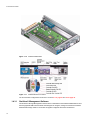
2.10.3 Engaging the Anti-tamper Locks
The anti-tamper locks are fitted in the drive carrier handles and are accessed through the small cutout in
the latch section of the handle.
Drives are supplied with the locks set in the locked position.
2.10.3.1
34
Activating the Locks
1
Carefully insert the lock key provided into the cutout in the handle.
2
Locate the key into its socket.
3
Rotate the key in a clockwise direction until the indicator is visible in the aperture beside the key.
Getting Started
Figure 2–15
4
Activating the Anti-tamper Lock
Remove the key.
De-activation is the reverse of this procedure, that is:
• Rotate the key in an anti-clockwise direction until the indicator is no longer visible in the aperture
beside the key.
Note
A drive carrier cannot be installed if its anti-tamper lock is activated outside the Enclosure.
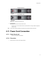
2.11 Power Cord Connection
2.11.1 Parts Check List
• Power cord to requisite local standards
2.11.2 Procedure
1
Attach the power cord to the Power Supply modules,
35
Enclosure User Guide
Figure 2–16 Cable Strain Relief Bales
2
Attach the power cord to the Power Distribution Unit (Figure 2–17) in the rack or other power source.
Figure 2–17 Power Cord Connections
Warning
3
Caution
Before applying power, carry out the grounding checks detailed in section 2.12.
A Power On LED on the Ops Panel indicates whether AC power is present.
The power connections must always be disconnected prior to removal of the Power Supply module from
the enclosure.
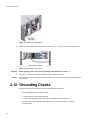
2.12 Grounding Checks
Perform these checks to ensure that a safe grounding system is provided.
• If a Rack Distribution System is being used.
– Ensure power is removed from the rack.
– Connect the FC60SS power cord to the rack distribution and the enclosure.
• If a direct connection is made with the FC60SS power cord, ensure that it is connected
to the enclosure.
36
Getting Started
Warning
Some electrical circuits could be damaged if external signal cables or power control cables are
present during the grounding checks.
• Check for continuity between the earth pin of the IEC 320 connector on one of the Power Supply
modules and any exposed metal surface of the FC60SS enclosure.
2.13 Embedded StorView Initial Setup
If this is the first startup of the Embedded StorView module, you will probably need to configure the
network settings.The Embedded StorView module supports both DHCP and manual network settings. By
default the Embedded StorView module will look for a DHCP server to obtain an IP address. If one is not
found, it will search to determine if an IP address had been previously assigned. If an address was not
previously assigned, then the system defaults to an IP address of:
– 10.1.1.5 for the lower RAID Controller (Controller 0)
– 10.1.1.6 for the upper RAID Controller (Controller 1)
– 10.1.1.7 if an error is detected
– Subnet Mask is 255.0.0.0
A tool is provided to configure new Embedded StorView modules. From Windows platforms it is access
via the Embedded link on the disc navigation menu and on Linux it is accessed via a command line
executable.
When the Embedded StorView Setup program is run, it will broadcast UDP packets and any Embedded
StorView module will reply with UDP packets containing their information. A list of “uninitialized” systems
is displayed. Uninitialized systems are those which have not had the default user name and password
changed. Even if a configuration is created with arrays and logical drives but the login name and
password have not been changed, it will still be considered an uninitialized system During the process of
configuring an Embedded StorView module, you will be required to enter a “new’ password and confirm
that password. The default password is “password.”
The Embedded StorView module is identified by its MAC and IP address. It may be more helpful during
setup to configure one Embedded StorView module at a time.You will find the MAC address located on
a label affixed to the top of the controller case or by accessing the VT-100 text-based menu function for
Embedded StorView Menu mode and viewing the network settings. Note the specific address of each
controller in multiple controller environments and the location where that specific controller is installed in
the enclosure.
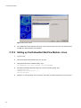
2.13.1 Setting up the Embedded StorView Module: Microsoft
Windows
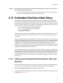
1
Insert the Software and Manuals CD into your CD drive. the autorun program will automatically start the
navigation menu, click on the link for the hardware (FC60SS) product which you have installed.
2
Click the Embedded StorView Setup link to begin the Setup Wizard.
3
You are presented with a Welcome screen and instructions to proceed. Review the information and click
the Next button. (Figure 2–18)
37
Enclosure User Guide
Figure 2–18 Welcome Screen
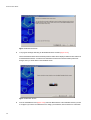
4
T he program will begin searching for Embedded StorView modules (Figure 2–19).
Those embedded modules with their default password intact will be displayed with their MAC address in
an Uninitialized list window. If all discovered embedded modules have had their default passwords
changed, then you will be taken to the Initialized screen.
Figure 2–19 Search Screen
5
38
From the Uninitialized screen (Figure 2–20), select the MAC address of the embedded module you wish
to configure.If you wish to use a DHCP server to assign your IP address, click the check box “Use DHCP.”
Getting Started
If you wish to manually configure your network setting, enter the correction information in the appropriate
fields.
Enter a new” password and confirm the new password. Click the Configure button.
Figure 2–20 Configuration Screen
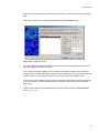
6
if you have additional uninitialized embedded modules, select the next MAC address and choose the
appropriate settings from the previous step.
Once you have completed configuring all the uninitialized embedded modules and have clicked the
Configure button, the wizard will display a popup message indicating all systems have beenconfigured.It
will then re-scan for systems and if none are found, you will be taken to the Initialized screen.
If someone plugs in a uninitialized module system to the network (same subnet mask) during the time of
the rescan or resets a system’s password back to the defaults, you will be taken to the Uninitialized
screen again.
7
Select the MAC address of the embedded module you wish to start and click the Launch StorView
button. (Figure 2–21)
39
Enclosure User Guide
Figure 2–21 Launch Screen
8
Your default web browser will open with a login screen. Enter the login name and “new” password then
click OK. The StorView Main screen will open.
2.13.2 Setting up the Embedded StorView Module: Linux
1
Log in as “root.”
2
Insert the Software & Manuals Disc into your CD drive.
3
Change directories to the software location. Type:
cd [CDROM mount point path]/software/ storview/embedded
4
Execute the Embedded StorView Setup Tool. From the command prompt, type:
./esvsetupcl-linux
Embedded StorView Setup Tool. v1.0
Entering Menu Mode.
5
40
Follow the on screen prompts. At the conclusion of the setup you will be instructed on how to proceed.
Operation
Chapter 3
Operation
3.1 Before You Begin
Before powering up the FC60SS enclosure please ensure that all the modules are firmly
seated in their correct bays.
3.2 Power On
Power on the enclosure by connecting cables to the PDU, or powering on the PDU, then power on the
Host system.
Caution
Note
Do not operate this equipment until the ambient temperature is within the specified operating range. If the
drives have been recently installed ensure they have had time to acclimatize before operating them.
Please refer to Section 3.5 for details of the Ops Panel LEDs and related fault conditions.
Follow the procedure below to Power On the enclosure.
1
Apply AC power to the enclosure.
2
The Power On LED on the Ops Panel should be lit (Green) when the enclosure power is activated (and
the disk drive motors should start).
Note
The Power On LED on the Ops Panel should be lit Green at power up to indicate that the system is
functioning correctly, all other Ops Panel LEDs are off. If any LEDs show Amber then a problem exists
and the procedure in Chapter 4 should be followed.
Important
If AC power is lost for any reason, on restoration of power the enclosure will re-start
automatically.
3.3 Power Supply Module LEDs
The Power Supply module incorporates 2 LEDs.
• Under Normal conditions the Power On LED should be illuminated constant GREEN
• If a problem is detected the Module Fault LED will be illuminated constant AMBER.
41
Enclosure User Guide
The Power Supply module LED states are detailed in Table 3–1.
Table 3–1 Power Supply LEDs
Power On & OK
(Green)
Module Fault
(Amber)
Status
Off
Off
No AC power (either PSU)
Off
On
No AC power (this PSU only)
Off
On
PSU Fault (over temp, over voltage, over current, PSU fan fail)
On
Off
AC present, PSU on and OK
On
On
Fan Fault
3.4 Cooling Module LED
The Cooling module incorporates a Module Fault LED (Amber), defined in Table 3–2).
Table 3–2
Cooling Module LED
Status
Module Fault (Amber)
Enclosure On - Fan OK
Off
Fan Fail
On
3.5 Ops Panel LEDs
The Ops Panel LEDs are shown in Figure 3–1 and the LEDs status conditions are defined in Table 3–3.
Figure 3–1
Important
42
Ops Panel LEDs and Switches
Chapter 4, ”Troubleshooting and Problem Solving”, on page 47 provides more information.
Operation
Table 3–3
Ops Panel LED States
Ops Panel LEDs
Other Associated
LEDs or Alarms
State Description
Power
On
System
Fault
Logical
Fault
Box
Identify
(Green/
Amber)
(Amber)
(Amber)
(Blue)
On
Off
Off
X
On
On
On
On
On
Off
X
X
On
On
X
X
PSU Fault LED or Any PSU Fault or Fan Fault
Over or Under temperature
Cooling Module
Fault LED
On
On
X
X
FC60SS RAID
Controller Fault
LED on lower
controller
ESI processor/ FC60SS RAID Controller 0 failed
On
On
X
X
FC60SS RAID
Controller Fault
LED on upper
controller
ESI processor/ FC60SS RAID controller 1 failed
On
Flashing
X
X
FC60SS RAID
Controller Fault
LED
On
Flashing
X
X
PSU Removed:
On
(X)
Off
X
On
(X)
On
X
Array in failed or
degraded state:
On
(X)
Flashing
X
Arrays in impacted Arrays performing background function
state:
X
X
X
On
Aux present, overall power failed or switched off.
single beep, two
double beep
Ops Panel power on (5s) test state
Power On, all functions good
• Unknown (invalid or mixed) module type installed, or
• 12C Bus Failure (inter ESI processor).
PSU removed when two were present at Start of Day
Power On, all functions good
Drive failure has occurred causing loss of availability or
redundancy.
SES controlled enclosure identify.
Note: “X” = no bearing on these states
43
Enclosure User Guide
3.6 FC60SS RAID Module LEDs
The FC60SS RAID module LEDs status conditions are defined in Table 3–4.
Table 3–4
FC600SS RAID Module LEDs
LED Functions
LED State
Definition
Controller Slot 0 Activity*
Amber
When ON the Controller is currently
processing data
Controller Slot 1 Activity*
Amber
When ON the Controller is currently
processing data
Controller OK
Green
Module OK
Controller Fault
Amber
Fault on this module
Cache Active
Amber
Active cache contents
Battery/Controller Fail
Amber
Fault in battery or charger operation of
controller
Host 0 Port Signal Good
Green
When ON the LED denotes that incoming
FC signal is good
Host 1 Port Signal Good
Green
When ON the LED denotes that incoming
FC signal is good
Host 0 Port Traffic*
Amber
When ON the Controller is processing data
on this port
Host 1 Port Traffic*
Amber
When ON the Controller is processing data
on this port
SAS Expansion 1*
Green
When ON this port is active
SAS Expansion 2*
Green
When ON this port is active
SAS Expansion 3*
Green
When ON this port is active
SAS Expansion 4*
Green
When ON this port is active
* These LEDs blink on/off when there is module activity.
44
Operation
3.7 Disk I/O Module LEDs
Table 3–5
Disk I/O Module LEDs
LED Functions
Host 0 & Host 1
(Green)
Expansion
(Green)
State
Description
ON
Flashing
OFF
Ready
Active
Not Ready
ON
Flashing
OFF
Ready
Active
Not Ready
3.8 Starting the Drives
Unless otherwise selected during installation, all drives in the enclosure should automatically start their
motors. If this has not occurred one of the following conditions may exist:
• There may be a power problem (an alarm and power fault indication would normally be active).
• If there is only one Power Supply Module present, the drive motors will spin up in a delayed
sequence.
3.8.1 Disk Drive LEDs
Each drive carrier incorporates two indicators, an upper (GREEN) and lower (AMBER).
• In normal operation the Green LED will be ON and will flicker as the drive operates.
• The Amber LED will be OFF In normal operation. It will only be ON if there is a drive fault.
• If the Green LED is OFF when the Amber LED is ON, a power control circuit failure is indicated.
3.9 Starting StorView
Upon start-up, embedded StorView looks at the user Preferences Settings to determine if an IP address
exists. If one is defined it will initialize the network interface using that IP address. In the event an IP
address is not defined, it attempts to get a DHCP IP address. You will need to contact your network
administrator for the IP address assigned by the DHCP server. To identify the new IP address lease, one
can look for ‘esv0’ or ‘esv1’ in your DHCP Manager software. If an IP address cannot be determined, the
software will use a default IP address of “10.1.1.5” for Controller 0 and “10.1.1.6” for Controller 1. If an
error is encountered, it will assign the Embedded StorView Server the IP address “10.1.1.7.”
• The first time you start StorView, you will need to configure the network settings. On the first startup,
you will be prompted for a user name and password. The default user name is “admin” and the
default password is “password.”. you should change your password to protect your array, please
refer to the Storview User Guide.
45
Enclosure User Guide
3.10 Power Down
The enclosure can be powered down at any time and if cached contents are present (refer to the Cache
Active LED on the RAID module), they will be preserved by the internal battery. If the enclosure is left in
this state for extended periods then the batteries will discharge and the cached data will be lost. It is
therefore recommended that, especially if the unit is to be powered down for extended periods, the
controller is shut down prior to powering off the enclosure.This will ensure that the cache is flushed to disc
and will prevent the battery from being discharged. Discharged batteries may also result in reduced
performance when the array is again powered up, because the write-back cache will be disabled until the
batteries are fully charged.
46
1
Shut down is requested at the GUI interface, please refer to StorView Storage Manager Software RAID
Module User Guide.
2
To power the Enclosure down, remove AC power at the power source.
Troubleshooting
Chapter 4
Troubleshooting and
Problem Solving
4.1 Overview
FC60SS enclosures include a processor and associated monitoring and control logic to
enable them to diagnose problems within the enclosure’s power, cooling and drive systems.
The sensors for power and cooling conditions are housed within the Power Supply modules. There is
independent monitoring for each unit.
If a fault is indicated on the Ops Panel, please refer to Table 4–3.
4.1.1 Initial Start-up Problems
4.1.1.1
Faulty Cords
First check that you have wired up the subsystem correctly. Then, if:
• cords are missing or damaged
• plugs are incorrect
• cords are too short
Call your supplier for a replacement.
4.1.1.2
Alarm Sounds On Power Up
Please refer to Section 4.3.
4.1.1.3
Green “Signal Good” LED on FC60SS RAID Module Not Lit
Check that the Rx and Tx cables have not been reversed during installation. Also check that the SFP is
properly seated and that the ends of optical cables are clean and undamaged. If the condition persists,
try replacing the SFP and/or cables.
4.1.1.4
1
Computer Doesn’t Recognize the FC60SS Enclosure
Check that the FC interface cables from the FC60SS enclosure to the host computer are fitted
correctly.
47
Enclosure User Guide
2
Check that all drive carrier modules have been correctly installed and that the LEDs on all installed drive
carrier modules are illuminated Green. Note that the drive LEDs will not be lit during drive spinup.
3
Check that there is a valid FC_AL signal present at the FC60SS connector by observing the state of the
LEDs Host Port 0 Signal Good and Host Port 1 Signal Good (see Figure 1–11 on page 10 and Table 4–
4 on page 51). If there is no signal present check that the cable has not been inverted during installation.
A green LED indicates that the signal is present. If there is no signal present see section 4.1.1.3 on
page 47.
4
Check the FC60SS RAID module setup as follows:
– Check that the FC60SS RAID module has been correctly installed and all external links and
cables are securely fitted.
– Check that the maximum cable length has not been exceeded.
5
Check that the FC60SS RAID module is properly set up at the Management Interface.
Important:
For details on how to remove and replace a plug-in module see Section 4.8.
4.2 Status Indicators (LEDs)
• Green LEDs are always used for good or positive indication.
• LEDs Flashing Green or Flashing Amber indicate that non-critical conditions exist.
• Solid Amber LEDs indicate there is a critical fault present within the module.
4.2.1 Power Supply Module LEDs
The Power Supply LED states are detailed in Table 4–1.
• Under Normal conditions the Power On LED should be illuminated constant GREEN
• If a problem is detected the Module Fault LED will be illuminated constant AMBER.
Table 4–1 Power Supply LEDs
48
Power On & OK
(Green)
Module Fault
(Amber)
Status
Off
Off
No AC power (either PSU)
Off
On
No AC power (this PSU only)
Off
On
PSU Fault (over temp, over voltage, over current, PSU fan fail)
On
Off
AC present, PSU on and OK
On
On
Fan Fault
Troubleshooting
4.2.2 Cooling Module LED
The Cooling module incorporates a Module Fault LED (Amber), defined in Table 4–2).
Table 4–2
Cooling Module LED
Status
Module Fault (Amber)
Enclosure On - Fan OK
Off
Fan Fail
On
4.2.3 Ops Panel LEDs
The Ops Panel displays the aggregated status of all the modules. The Ops Panel LEDs are shown in
Figure 4–1 and defined in Table 4–3.
Note
The Ops Panel is supplied as an integral part of the enclosure core product and is not user replaceable.
Figure 4–1
Ops Panel
49
Enclosure User Guide
Table 4–3
Ops Panel LED States
Ops Panel LEDs
Other Associated
LEDs or Alarms
State Description
Power
On
System
Fault
Logical
Fault
Box
Identify
(Green/
Amber)
(Amber)
(Amber)
(Blue)
On
Off
Off
X
On
On
On
On
On
Off
X
X
On
On
X
X
PSU Fault LED or Any PSU Fault or Fan Fault
Over or Under temperature
Cooling Module
Fault LED
On
On
X
X
FC60SS RAID
Controller Fault
LED on lower
controller
ESI processor/ FC60SS RAID Controller 0 failed
On
On
X
X
FC60SS RAID
Controller Fault
LED on upper
controller
ESI processor/ FC60SS RAID Controller 1 failed
On
Flashing
X
X
FC60SS RAID
Controller Fault
LED
On
Flashing
X
X
PSU Removed:
On
(X)
Off
X
On
(X)
On
X
Array in failed or
degraded state:
On
(X)
Flashing
X
Arrays in impacted Arrays performing background function
state:
X
X
X
On
Note
50
Aux present, overall power failed or switched off.
single beep, two
double beep
Ops Panel power on (5s) test state
Power On, all functions good
• Unknown (invalid or mixed) module type installed, or
• 12C Bus Failure (inter ESI processor).
PSU removed when two were present at Start of Day
Power On, all functions good
“X” = no bearing on these states
Drive failure has occurred causing loss of availability or
redundancy.
SES controlled enclosure identify.
Troubleshooting
4.2.4 FC60SS RAID Module LEDs
The FC60SS RAID module incorporates the following LED indicators: For details on how to remove and
replace a FC60SS RAID module see Section 4.11.
Table 4–4
FC60SS RAID Module LEDs
LED Functions
LED State
Definition
Controller Slot 0 Activity*
Amber
When ON the Controller is currently processing data
Controller Slot 1 Activity*
Amber
When ON the Controller is currently processing data
Controller OK
Green
Module OK
Controller Fault
Amber
Fault on this module
Cache Active
Amber
Active cache contents
Battery/Controller Fail
Amber
Fault in battery or charger operation of controller
Host 0 Port Signal Good
Green
When ON the LED denotes that incoming FC signal
is good
Host 1 Port Signal Good
Green
When ON the LED denotes that incoming FC signal
is good
Host 0 Port Traffic*
Amber
When ON the Controller is processing data on this
port
Host 1 Port Traffic*
Amber
When ON the Controller is processing data on this
port
SAS Expansion 1*
Green
When ON this port is active
SAS Expansion 2*
Green
When ON this port is active
SAS Expansion 3*
Green
When ON this port is active
SAS Expansion 4*
Green
When ON this port is active
* These LEDs blink on/off when there is module activity.
4.2.5 Disk I/O Module LEDs
Table 4–5
Disk I/O Module LEDs
LED Functions
Host 0 & Host 1
(Green)
Expansion
(Green)
State
Description
ON
Flashing
OFF
Ready
Active
Not Ready
ON
Flashing
OFF
Ready
Active
Not Ready
51
Enclosure User Guide
4.2.6 Drive Carrier LEDs
Please refer to Table 4–6 on page 52.
4.3 Audible Alarm
The enclosure subsystem includes an Audible Alarm which indicates when a fault state is present. The
following conditions will activate the Audible Alarm:
• Fan Fault
• Voltage out of range
• Over temperature
• Thermal overrun
• System fault
• Logical fault
• PSU Fault
• Removal of 1 PSU
• Invalid cabling
4.3.1 Audible Alarm Mute
When the Audible Alarm sounds, it may be muted by pressing the Alarm Mute push-button, located on
the enclosure front panel. Automatic muting will take place after two minutes if the mute switch is not
manually operated.
When the alarm is muted it will continue to sound with short intermittent beeps to indicate that a problem
still exists, It will be silenced when all problems are cleared. (See also Section 4.5.5 on page 55).
4.3.1.1
LED Test Mode
The Alarm Mute push-button can also be used to activate the self- test feature for the LEDs on the Ops
Panel. The test is activated when you press the Mute push-button while no faults are present. While the
test is running all LEDs will flash.
4.4 Drive Carrier Module Faults
Disk drive status is monitored by a green LED and an amber LED mounted on the front of each Drive
Carrier module (see Figure 4–2), providing the following indications:
Table 4–6
52
Drive Carrier LED Functions
State
Green
Amber
No drive fitted
Off
Off
Drive Power ON
On
Off
Drive Activity
On/Blink off
Off
Drive Impacted
On
Blink
Troubleshooting
Table 4–6
Drive Carrier LED Functions
State
Green
Amber
Drive Fault
On
On
Power control circuit failure
Off
On
Notes
1 Drive Activity - LED may be off for a length of time during power up.
2 Impacted - any background service, e.g. initialization
Figure 4–2 Drive Carrier LEDs
4.4.1 Auto Start Failure
Unless otherwise selected at installation time, all drives in the enclosure should automatically start their
motors after power is applied. If this has not occurred there is a power problem (An alarm and power fault
indication would normally be active).
4.5 Troubleshooting
The following sections describe problems, with possible solutions, which can occur with your FC60SS
Enclosure Platform.
4.5.1 System Faults
Symptom
1 The CONTROLLER
FAULT LED will
illuminate AMBER on
the FC60SS module
2 Audible Alarm sound
Note
Cause
Action
The ESI processor
Replace faulty module as appropriate:
has detected an
– PSU
internal fault on one of
– Cooling
– FC60SS RAID
the following modules:
– PSU
– Cooling
– FC60SS
RAID
See also Section 4.5.5.
53
Enclosure User Guide
4.5.2 Power Supply Faults
Symptom
1 Ops Panel SYSTEM
FAULT LED AMBER
Cause
1 Any power fault.
Action
1 Check AC power connections to Power
Supply module are live.
2 A fan failure.
2 An AMBER LED on
one or more Power
Supply modules.
3 Audible Alarm
sounding.
3 A thermal
condition which
could cause PSU
overheating.
2 Disconnect the Power Supply module from
AC power and remove the module from the
system, Re-install: if problem persists,
replace Power Supply Module.
3 Reduce the ambient temperature.
4 Fault: on one of
the following
modules:
– PSU
– Cooling
– FC60SS RAID
4 Replace faulty module as appropriate:
– PSU
– Cooling
– FC60SS RAID
5 Removal of 1
PSU
4.5.3 Thermal Control
FC60SS enclosures use extensive thermal monitoring and take a number of actions to ensure
component temperatures are kept low and also to minimize acoustic noise. Air flow is from front to rear
of the enclosure.
Symptom
Cause
If the ambient air is cool
(below 25 °C) and the fans
are observed to increase in
speed then some restriction
on airflow may be causing
additional internal
temperature rise.
The first stage in the thermal
control process is for the fans
to automatically increase in
speed when a thermal
threshold is reached. This
may be caused by higher
ambient temperatures in the
local environment and may
be perfectly normal.
Note: This is not a fault
condition.
Note: This threshold
changes according to the
number of drives and power
supplies fitted.
Action
1 Check the installation for any airflow
restrictions at either the front or rear
of the enclosure. A minimum gap of
25mm at the front and 50mm at the
rear is recommended.
2 Check for restrictions due to dust
build-up, clean as appropriate.
3 Check for excessive re-circulation of
heated air from rear to the front. Use
in a fully enclosed rack installation is
not recommended.
4 Check that all Blank modules are in
place.
5 Reduce the ambient temperature.
54
Troubleshooting
4.5.4 Thermal Alarm
Symptom
1 Ops Panel SYSTEM
FAULT LED AMBER.
2 An AMBER LED on
one or more Power
Supply module.
3 Audible Alarm
Sounding.
Cause
1 If the internal temperature
measured in the airflow
through the enclosure
exceeds a pre-set
threshold a thermal alarm
will sound.
2 Cooling Module failure
4 Air temperature
exiting PSU above
55°C.
Action
1 Check local ambient environment
temperature is below the upper 40°C
specification.
2 Check the installation for any airflow
restrictions at either the front or rear
of the enclosure. A minimum gap of
25mm at the front and 50mm at the
rear is recommended.
3 Check for restrictions due to dust
build-up, clean as appropriate.
4 Check for excessive re-circulation of
heated air from rear to the front. Use
in a fully enclosed rack installation is
not recommended.
5 If possible shutdown the enclosure
and investigate the problem before
continuing.
6 Replace Cooling Module
4.5.5 Thermal Warnings
Symptom
Cause
Action
1 ALL AMBER LEDs
on the Ops Panel
and on ALL drive
bays illuminated
flash.
At a higher threshold than the
Thermal Alarm (this should
already have been activated).
1 Switch Off immediately.
OR - All fans have failed.
3 Check Power Supply module faults.
2 Audible Alarm
sounds almost
continuously and
cannot be muted.
OR - Only 1 fan operating and
the internal temperature is 40° C
or above.
4 Check for excessive local
temperatures.
2 Check for airflow restrictions.
55
Enclosure User Guide
4.6 Dealing with Hardware Faults
Ensure that you have obtained a replacement module of the same type before removing any faulty
module.
Warning
If your FC60SS enclosure is powered up and you remove any module, replace it
immediately. If the enclosure is used with plug-in modules, dummy carriers or blank modules
missing for more than a few minutes, the Enclosure can overheat, causing power failure and data
loss. Such use will invalidate the warranty.
• Replace a faulty drive with a drive of the same type and equal or greater capacity.
• All drive bays must be fitted with a Drive Carrier or Dummy Carrier module in order to maintain a
balanced air flow.
• All of the supplied plug-in power supply units, electronics modules, dummy carriers and blank
modules must be in place for the air to flow correctly around the cabinet.
4.7 Continuous Operation During
Replacement
Depending on how the FC60SS enclosure is configured, if a disk unit fails, it can normally be
replaced without interrupting the use of the system.
In addition, each enclosure contains two Power Supply modules, either of which can maintain power and
cooling to the subsystem while the other is replaced.
Note: The PSU replacement time must be as short as possible as the FC60SS
enclosure is designed to operate with two PSUs installed.
Important
The fans within the Cooling module are not user replaceable, in the event of a cooling fan failure
the complete Cooling module must be replaced.
4.7.1 Ops Panel
Important
The Ops Panel is an integral part of the enclosure assembly and can only be replaced with a
replacement enclosure. The enclosure should only be replaced by trained personnel.
4.8 Replacing a Module
Warning
Whenever replacing a module NEVER leave an EMPTY space in the rear of the enclosure, obtain
a replacement before removing the problem part.
Please refer to Chapter 2 , ”Getting Started” for information on the initial installation of the plug-in modules
in the FC60SS enclosure.
Warning
56
Observe all conventional ESD precautions when handling FC60SS modules and
components. Avoid contact with Backplane components and module connectors, etc.
Troubleshooting
4.9 Power Supply Modules
Warning
The FC60SS enclosure must only be operated with two Power Supply modules
installed.
4.9.1 Removing a Power Supply Module
Warning
Do not remove the faulty Power Supply module unless you have a replacement unit of the correct
type ready for insertion. the system must not be operated without both PSUs in place.
As there should always be two power supply units installed, you can continue working while replacing the
faulty module.
1
Make sure you identify the faulty Power Supply module correctly, from the two modules installed.The
Module Fault LED on the faulty PSU will be illuminated Amber.
2
Switch off the PSU and disconnect the power cord.
3
Push the latch on the PSU handle to the right (Figure 4–3), grip the handle and pull the PSU out of the
enclosure.
Warning
Do not remove covers from the Power Supply (PSU). Danger of electric shock inside. Return the
PSU to your supplier for repair.
Figure 4–3
Removing a Power Supply Module
4.9.2 Installing a Power Supply Module
Warning
Do not mix Power Supply modules of different types or makes.
57
Enclosure User Guide
1
Caution
Check for damage, especially to the rear connector on the PSU.
Handle the module carefully and avoid damaging the connector pins. Do not install the module if any pins
appear to be bent.
2
Slide the module into the enclosure (Figure 4–4).
3
Push the module home. A click should be heard as the handle latch engages.
4
Connect the power supply cords to the power source.
Note
The alarm will sound until the new Power Supply module is operating correctly.
Figure 4–4 Inserting an Power Supply Module
58
Troubleshooting
4.10 Cooling Module
4.10.1 Removing a Cooling Module
1
Grasp latch (Figure 4–5) between thumb and forefinger. Squeeze thumb and forefinger together to
release the latch.
Figure 4–5 Cooling Module Latch
2
Pull the latch outward to cam the module out of the enclosure (Figure 4–6).
3
Withdraw the module.
Figure 4–6 Removing a Cooling Module
59
Enclosure User Guide
4.10.2 Installing a Cooling Module
1
Caution
Check for damage, especially to the rear connector on the supply.
Handle the module carefully and avoid damaging the connector pins. Do not install the module if any pins
appear to be bent.
2
With the latch in the open position (see Figure 4–5), slide the module into the enclosure until the latch
engages automatically (see Figure 4–7).
3
Cam the module home by manually closing the latch.(Figure 4–5). A click should be heard as the module
latches engage.
Figure 4–7 Cooling Module Installation
4.11 FC60SS RAID Module
Caution
If only one FC60SS RAID module is fitted then a Blank module MUST be fitted in the unused slot, there
will be inadequate drive cooling if the slot is left open.
The following procedures apply to both the FC60SS RAID module and the Blank (FC60SS) module.
4.11.1 Removing an FC60SS RAID Module
60
Warning
Do not remove this module unless a replacement can be immediately added. The system must not
be run without all modules in place.
1
Using two hands, grasp each latch between the thumb and forefinger of each hand. Squeeze thumb and
forefinger together to release the latch.
Troubleshooting
2
Pull the latches outward to cam the module out of the enclosure (Figure 4–10).
3
Grip the latch handles and withdraw the module (Figure 4–8).
Figure 4–8
Removing a FC60SS RAID Module (1)
Figure 4–9
Removing a FC60SS RAID Module (2)
61
Enclosure User Guide
4.11.2 Installing an FC60SS RAID Module
Important
Host and Expansion Connectors:
Class 1 Laser Product
• If fitted with optical modules, the modules must be a UL (or other North American NRTL)
RECOGNISED COMPONENT, must be approved by TUV (or other European Product safety
test house) and the laser in the module must comply with Laser Class 1, US 21 CFR (J) & EN
60825-1.
EMC Precautions:
If passive copper cables are connected, the cable must not have a connection to a common
ground/earth point.
62
1
Check for damage, especially to the interface connector - do not install if the pins are bent.
2
With the latches in the open position (see Figure 4–10), slide the FC60SS RAID module into the enclosure
until the latches engage automatically (Figure 4–11).
Figure 4–10
FC60SS RAID Module Latch Operation
Figure 4–11
Installing a FC60SS RAID Module (step 2)
Troubleshooting
3
Cam the module home by manually closing the latches (see Figure 4–12).
Figure 4–12
4
Note
Installing a FC60SS RAID Module (step 2)
A click should be heard as the latches engage.
The FC60SS RAID module will take up to 1 minute to re-initialize onto the loop after re-cabling.
4.12 Battery Module
Warning
There is a danger of explosion if the battery is incorrectly replaced.
Dispose of used batteries in accordance with the manufacturer’s instructions and national regulations.
4.12.1 Removing a Battery Module
1
Operate the release latch and slide the Battery module out of the FC60SS RAID module (Figure 4–13).
63
Enclosure User Guide
Figure 4–13
Removing a Battery Module)
4.12.2 Installing a Battery Module
1
Check for damage, do not install if there are any outer signs of damage.
2
Slide the Battery module into the vacant slot on the right hand side of the FC60SS RAID module
(Figure 4–14).
Figure 4–14
64
Battery Assembly Installation
Troubleshooting
4.13 Removing/Replacing Disk I/O
Modules
To remove/replace a Disk I/O module, please follow the procedures for Removing and Replacing a
FC60SS RAID Module as defined in sections 4.11.1 on page 60 and 4.11.2 on page 62.
4.14 Drive Carrier Module
Warning
Observe all conventional ESD precautions when handling FC60SS modules and
components. Avoid contact with backplane components and module connectors, etc.
4.14.1 Removing a Drive Carrier Module
Caution
1
Note
Drive spin down
Damage can occur to a drive if it is removed while still spinning, we recommend that you perform All steps
of the following procedure to ensure that the drive has stopped prior to removal:
Release the carrier handle, by pressing the latch in the handle towards the right (Figure 4–15).
The anti-tamper lock must be off.
Figure 4–15 Removing a Drive Carrier Module (step 1)
2
Gently withdraw the Drive Carrier module approximately 1 inch (25mm) and wait 30 seconds.
3
Withdraw the module from the drive bay (Figure 4–16).
65
Enclosure User Guide
Figure 4–16 Removing a Drive Carrier Module (step 3)
4.14.2 Installing a Drive Carrier Module
Warning
All drive bays must be fitted with Drive Carrier modules or Dummy Carrier modules to maintain a
balanced air flow.
4.14.2.1
Drive Carrier Configuration
Important
Before you install the drive carrier modules in your FC60SS enclosure, please refer to
Section 2.2 on page 19 for system configuration information.
4.14.3 Installation Procedure
66
Important
Ensure that the carrier is orientated so that the drive is uppermost and the handle opens from the
left.
1
Release the carrier handle, by pressing the latch in the handle towards the right (Figure 4–17) and insert
the carrier into the enclosure.
Troubleshooting
Figure 4–17 Drive Carrier Module with Handle Released
Note: If the anti-tamper locks have been activated, please refer to section 2.10.3, ”Engaging the
Anti-tamper Locks”, on page 34
2
Slide the carrier, gently, all the way into the enclosure until it is stopped by the camming lever on the right
of the carrier (Figure 4–18)
Figure 4–18
3
Installing a Drive Carrier Module (step 2)
Cam the carrier home - the camming foot on the base of the carrier will engage into a slot in the enclosure.
Continue to push firmly until the handle fully engages. A click should be heard as the latch engages and
holds the handle closed (Figure 4–15).
67
Enclosure User Guide
Caution
Ensure that the carriers are fully engaged in the enclosure, as shown in Figure 4–19.
Figure 4–19 Engaging a Drive Carrier Module in an Enclosure
4.14.4 Dummy Drive Carrier Module Removal/Replacement
Dummy drive carrier modules are removed and replaced in the enclosure simply by pulling the module
out of the enclosure or pushing it into place.
4.15 Spare Parts and Ancillary Items
The following replaceable parts are available for FC60SS SAS Enclosure Platform:
• Chassis including Backplane and integrated Ops Panel
• 350W AC Power Supply Module
• Drive Carrier Module
– LC - LC optical cables (500m length)
• FC60SS RAID Module (512Mb DDR2 SDRAM)
– RS232 cable
• FC60SS RAID Module (1024Mb DDR2 SDRAM)
– LAN cable
• Cooling Module
– SAS cables
• Battery Module
– SATA cables
• Dummy Drive Carrier Module
68
• Cables:
– External FC-AL Interface Cables
• Blank I/O Module (FC60SS/Expansion)
• Power Cords (Country specific)
• Disk I/O Module
• All documentation
• SFP module, optical
• Keys, Anti-tamper Lock (for Drive Carrier
modules).
Index
Index
a
airflow 14
Alarm Mute push-button 52
anti-static wrist or ankle strap 21
anti-tamper lock 13, 34, 65
Audible Alarm 5, 52, 53, 54, 55
Auto Start Failure 53
auto start failure 53
Dummy Drive Carrier Module Removal/
Replacement 68
e
Enclosure 2, 14, 56
Enclosure Chassis features 3
Enclosure Configuration 27
Enclosure Drive Bay Numbering
Convention 20
Enclosure Installation Procedures 21
Enclosure System Interface/Operators
Panel 4
Enclosures Expansion 32
Engaging the Anti-tamper Locks 34
ESD precautions 21, 56, 65
ESI processor 53
Ethernet cable 9, 31
Ethernet Connection 31
b
Backplane 2, 3, 9, 12, 21, 25, 56, 65
Battery module 11
bay 12, 19
Blank Modules 2, 3, 6, 14, 19, 56
c
chassis 2, 3, 25
chassis assembly 3
Chassis Installation 25
CONTROLLER FAULT LED 53
Cooling Module 2, 3, 7, 56
Cooling Module Fault LED 8
f
FC60SS RAID module 2, 3, 6, 9, 27, 53,
62
FC60SS RAID Module LEDs 9, 44, 51
fan failure 54
FC_AL signal 48
Fibre Channel Interface 27
d
direct power connection 36
disk drive 3, 20
Disk Drive LEDs 45
Disk drive status 52
Disk I/O module 3, 6, 12
Disk I/O Module LEDs 12, 45, 51
Drive Bay 19
Drive Carrier Configuration 20, 66
drive carrier handle 13
Drive Carrier Module 2, 3, 6, 13, 20, 45,
48, 65, 66
Drive Carrier Module LEDs 48, 52
Drive Location Rules 33
Drive Slot Arrangement 33
Drive spin down 65
Drive Start 34
Drive Status Indicators 13
Dummy Carrier module 6, 14, 20, 56,
66
g
Grounding Checks 36
h
Hardware Faults 56
HBA 21
Host Bus Adaptors (HBAs) 27
i
IEC 320 connector 37
Installing a Battery Module 64
Installing a Cooling Module 60
Installing a Drive Carrier Module 66
Installing a Power Supply Module 57
Installing an FC60SS RAID Module 62
69
Enclosure User Guide
m
FC60SS-XPN enclosures
33
RS232 socket 9
Module Fault LED 41, 57
o
Operator’s (Ops) Panel 2, 4
Ops Panel 4, 9, 12, 25, 36, 49, 56
Ops Panel LEDs 4, 41, 42, 49, 52
optical SFP components 27
s
SAS patch cables 32
SES Management Services 20
SFP port 9
Slot 0 location 2
Slot 1 location 2
Small Form Factor Pluggable (SFP)
modules 9
Spare Parts and Ancillary Items 68
Starting the Drives 45
Status Indicators (LEDs) 48
StorView ® Storage Management
software 10, 26
switch ports. 27
System airflow 7
SYSTEM FAULT LED 54, 55
System Faults 53
p
PDU 41
plug-in module 2, 3, 19
power cord 35, 57
Power Cord Connection 35
power cords 19
Power Distribution Unit 21, 36
Power Down 46
Power On 41
Power On LED 36, 41
Power Supply Faults 54
Power Supply LEDs 6, 41, 54, 55
Power Supply module 2, 3, 6, 7, 19, 35,
37, 55, 56, 57, 58
PSU 9, 12, 57
PSU LEDs 41, 48
PSU voltage operating ranges 6
r
12, 32,
t
Thermal Alarm 55
Thermal Control 54
Thermal Warnings 55
Troubleshooting 53
u
Rack Distribution System 36
Unpacking the Enclosure System
Rack Installation Pre-Requisites 22
UPS 21
Rack Mounting Rail Kit 22, 25
RAID Configuration Utility interface,
menu-based 26
RAID Configuration Utility interface, text
Visible Alarms 5
based 27
Removing a Battery Module 63
Removing a Cooling Module 59
Removing a Drive Carrier Module 65
Removing a Power Supply Module 57
Removing an F60SS RAID Module 60
Removing/Replacing Disk I/O
Modules 65
Replacing a Module 56
RJ45 10/100/BaseT Ethernet port 9, 31
FC60SS-1220 enclosure 2, 4, 5, 6, 7, 19, 20,
21
v
70
21