1
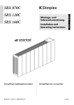
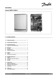
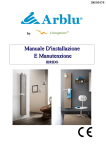
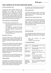
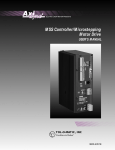
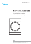
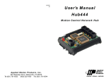
Dimplex SmartRad Fan Convector
SRX 080M, SRX 120M, SRX 140M & SRX 180M
EN
DE
srx_en-de_ba 12/10/A
The product complies with the European Safety Standards EN60335-1 and the European Standard Electromagnetic Compatibility (EMC) EN55014, EN60555-2
and EN60555-3. These cover the essential requirements of EEC Directives 2006/95/EC and 2004/108/EC
(b)
4
100
MIN
(c)
150
MIN
1
535
(a)
150
MIN
(d)
235
MIN
82
125
MIN
100
590
MIN
180
362
2
38
30
A
B
C
D
SRX 080
503
324
396
386
SRX 120
670
492
564
564
SRX 140
740
562
634
624
SRX 180
911
732
804
794
3
K
D
C
B
A
J
15
50 50
150
220
H
G
F
E
5
6
L1
N
P
L1
N
P
7
Power Output
3
SRX180 2
1
3
SRX140 2
1
3
SRX120 2
1
3
SRX80 2
1
35°C
1631
1079
641
1299
838
493
1120
719
415
759
479
251
45°C
2734
1803
1069
2177
1403
823
1878
1201
693
1273
801
419
Q = 450 l/h
55°C
3844
2530
1499
3061
1968
1154
2641
1686
971
1790
1124
588
65°C
4959
3260
1929
3951
2536
1484
3408
2172
1249
2050
1448
756
3
SRX180 2
1
3
SRX140 2
1
3
SRX120 2
1
3
SRX80 2
1
35°C
1480
1020
625
1199
802
484
1044
691
408
719
465
249
45°C
2502
1713
1044
2024
1346
808
1760
1160
683
1210
780
416
Q = 300 l/h
55°C
3520
2406
1464
2850
1892
1133
2479
1629
957
1705
1095
582
65°C
4546
3102
1885
3682
2439
1459
3202
2100
1231
2203
1412
749
3
SRX180 2
1
3
SRX140 2
1
3
SRX120 2
1
3
SRX80 2
1
35°C
1059
820
558
900
671
442
806
591
379
587
413
237
45°C
1832
1408
948
1558
1151
749
1394
1010
641
1012
704
399
Q = 150 l/h
55°C
2648
2021
1346
2256
1651
1063
2016
1447
907
1460
1005
564
65°C
3498
2655
1750
2984
2167
1378
2668
1894
1174
1926
1309
728
3
SRX180 2
1
3
SRX140 2
1
3
SRX120 2
1
3
SRX80 2
1
35°C
852
695
506
752
591
411
689
530
357
530
387
231
45°C
1431
1167
848
1269
995
691
1164
894
599
902
655
387
Q = 100 l/h
55°C
2020
1647
1175
1798
1355
955
1557
1215
828
1190
884
534
65°C
2559
2109
1542
2263
1793
1251
2070
1606
1083
1580
1163
694
3
SRX180 2
1
3
SRX140 2
1
3
SRX120 2
1
3
SRX80 2
1
35°C
551
487
394
511
436
338
480
402
302
392
312
207
45°C
918
812
657
852
728
564
802
672
504
655
522
345
Q = 50 l/h
55°C
1284
1136
920
1193
1020
791
1124
943
707
921
734
486
65°C
1649
1460
1183
1535
1313
1019
1446
1215
912
1191
950
627
55/47°C
3925
2424
1395
2982
1828
1039
2506
1541
856
1595
956
516
65/50°C
4628
2879
1636
3492
2154
1176
2924
1770
1017
1777
1137
607
3
SRX180 2
1
3
SRX140 2
1
3
SRX120 2
1
3
SRX80 2
1
Q
35/30°C
1495
893
522
1078
631
344
870
561
331
573
358
201
45/40°C
2856
1760
1008
2172
1329
752
1826
1119
621
1165
695
375
-1Dimplex SmartRad fan convector
EN
Models: SRX 80, SRX 120, SRX 140 & SRX 180
PLEASE STORE THESE INSTRUCTIONS IN A SAFE PLACE.
Technical data
Important safety information
The air inlet and outlet guards must not be covered or
blocked.
Before performing maintenance work on the device, disconnect it from the power supply.
THE DEVICE MUST BE GROUNDED.
The heater must not be installed directly below a permanently
installed socket. Combustible materials or liquids and other
highly flammable furnishings must be kept away from the
heater.
For the necessary minimum distances (in mm), see fig. 4.
Install the device such that it is not possible for someone in
the bath or shower to touch the control elements.
The heater must not be operated in very dusty areas.
This device is not suitable for children or persons who cannot
use the device safely as a result of physical or mental disability
or reduced perception without the assistance or supervision
of another person. Children should be supervised to ensure
they do not play with the device.
A warning symbol is attached to the heater. This indicates that the device must not be covered.
The operating instructions belong to the device and
must be stored in a safe place. If the owner changes, the operating instructions should be passed on to the new owner.
IMPORTANT – If the mains cable of the device is damaged, it
must be replaced by the manufacturer, a customer service
representative or a similarly qualified person.
Always ensure proper operation.
Device description
The SmartRad model is a fan convector for heating living spaces.
The fan convector is intended for connection to a central heating system. The fan convector is suitable for use in heat pump
systems, but it can also be operated in conjunction with other
heating systems, e.g. with oil or gas fires. The device draws in air
from the underside. This is heated up in the heat exchanger and
discharged at the top.
Fig. 1:
(a) Casing cover
(b) Control panel
(c) Air outlet guard
(d) 1 m connection cable
Fan convectors may only be used in central heating systems
with a closed control circuit.
The heating system must be operated as a dual-pipe system.
The devices must be of a sufficient rating such that they can
compensate for heat losses in the room.
Heat output (kW) at
flow temperature of
45°C
Temperature range
of flow temperature (°C)
Maximum permissible
flow temperature (°C)
Permissible operating
overpressure (MPa)
Pressure drop (kPa)
Air volume flow (m³/h)
Sound pressure level at
1 m (dB(A))
2
SRX 80
SRX 120
SRX 140
SRX 180
0.70
1.10
1.40
1.80
25 – 85
85
1
3
2
1
3
2
1
11.3
228
125
60
Nominal voltage
Power consumption
of fan (W)
3
2
1
Standby energy
consumption (W)
Protection category
Volume of
heat exchanger (ml)
Dimensions
W x H x D (mm)
Weight (kg)
26
19
16
13.1
345
190
100
13.7
410
225
120
47
38
27
~ 230 V, 50 Hz
43
56
29
36
20
24
15.8
540
300
160
50
33
23
<1
IP 20
310
430
480
600
503 x
530 x
145
12
670 x
530 x
145
15
740 x
530 x
145
17.5
911 x
530 x
145
22
Installation preparation
Remove packaging material.
Unscrew the four fixing screws from underside of device (see
fig. 2) to remove casing cover. Store casing cover such that it
cannot be damaged during installation.
Fixing to the wall
For drywalls, use suitable fixing material (not supplied)!
Draw and drill four holes on a sturdy wall as shown in fig. 4. All
dimensions are in mm.
Insert dowels and pre-fit the two top screws (don't completely
screw in yet).
Hang device on the two top screws.
Insert and tighten the two bottom screws, then tighten the two
top screws.
Hydraulic connection
To ensure a sufficient heating water flow rate through the fan
convectors, observe the following points:
- The devices are not suitable for installation in single-pipe
systems.
- The nominal width of the connection pipe must have a
minimum diameter of 15 mm.
- If the devices are installed in a heating system with various
heat distribution systems (e.g. underfloor heating), a separate circuit is required to guarantee a sufficient water flow
rate.
- For optimum operation (heat output) of the fan convectors,
-2a hydraulic balance is required on the heating system.
Fig. 5 shows the various hydraulic connection options on the
device. The recommended flow and return connections are
shown in fig. 5 and fig. 4 (below). The heating pipes can be laid
in the floor or in the wall. The device is supplied with two copper pipes with a diameter of 15 mm that are fitted on the heat
exchanger at the factory.
Before and during filling of the heating system, all pipe connections must be checked for leaks. During filling, the bleeder valve
(see fig. 4) must be open such that air can escape from the device. If necessary, bleed again following commissioning (circulating pump running).
Electrical connection
WARNING: The device must be grounded.
WARNING – phase conductor (brown) and neutral conductor
(blue) must not be swapped as this may cause malfunctions.
The electrical connection should have a supply voltage of ~230240V, 50 Hz.
The device must be installed by a qualified electrician in compliance with the existing standards and local installation guidelines.
Before performing installation, ensure that the power supply is
switched off.
The device is equipped with a flexible 1 m connection cable (4 x
0.75 mm²), which can be used to connect the heater directly to
the power supply via a suitable wall socket.
In the electrical supply line, fit a circuit breaker for each pole
with a contact opening width of at least 3 mm. Automatic fuses
are also permitted as separators. Automatic fuses should have a
delayed tripping characteristic.
Conductor configuration of the connection cable:
Brown: 'L' – supply voltage phase conductor
Blue: 'N' – supply voltage neutral conductor
Green/yellow: 'PE' grounding conductor
Black: control conductor (temperature reduction; on/off)
For circuit diagram, see fig. 6.
Control conductor
The black control conductor has the following functions:
Lowering temperature using an external timer or switch
By activating the control conductor, see fig. 6 on the left, the set
target temperature on the device is lowered.
The temperature reduction is forwarded to any downstream
devices via the control conductor.
Operation with programming cassette
The control signals of the programming cassette, which is
plugged into the pilot device, are forwarded to any downstream
devices via the control conductor, see fig. 6 on the right.
The control conductor does not have to be in phase with the
supply connection. If the control conductor is not used, it must
be properly insulated.
WARNING – if you switch over to controlled operation, the
mains voltage is on this conductor!
WARNING – do not ground the control conductor.
When taking out of service, e.g. for maintenance work, ensure
that both the mains supply and the control conductor are disconnected from the power supply, because this may result in
external voltage (via a timer contact or pilot device with pro-
gramming cassette).
Final installation
Fit casing cover following completion of installation work. To do
this, screw in the four fixing screws on the underside of the device, see fig. 2.
Operation
The control panel is shown in fig. 3.
The individual elements have the following meaning:
A – Operating mode button
B – On/off indicator
C – Manual mode indicator
D – Automatic mode indicator
E – Fan level button
F – Low fan level indicator
G – Medium fan level indicator
H – High fan level indicator
J – Thermostat setting wheel
K – Cover for programming cassette slot
Manual operation
Press the button once or several times until the yellow
indicator lights up.
Press the
button once or several times to select the desired fan level (fan speed). The set fan level is indicated by
the red indicator (1, 2, 3). Set the desired room temperature with the knob. The set fan level is switched on and off
depending on the room temperature. The temperature reduction is forwarded to any downstream devices via the control
conductor.
Automatic mode (eco)
Press the
button once or several times until the red eco
indicator lights up.
Set the desired room temperature with the knob. Depending on the current room temperature and the target temperature set on the thermostat, the electronics calculate
which of the three fan levels (fan speeds) to use. The electronics select the required fan level depending on the difference between the current room temperature and the desired target temperature.
If necessary, the number of possible fan levels can be reduced.
For instance, to limit the fan levels to a maximum of 2, press
the button once or several times until the red 2 indicator
lights up.
Operation with a programming cassette or a timer can only take
place in automatic mode (eco). If there is a control signal, the
green eco indicator lights up.
-3Fault indication
Cleaning outer surfaces
If the water temperature is too low, operation of the device is
interrupted and the red
indicator flashes. In this instance,
check that the heating system and circulating pump are operating correctly. For more information, please refer to the "Troubleshooting" chapter.
The heater must be switched off and cooled for cleaning. The
surfaces of the heater can be cleaned by wiping with a soft,
damp cloth and then dried. Do not use abrasive powder or furniture polish to clean as these may damage the surface.
Maintenance – to be performed by a specialist
Operation with air/water heat pumps
When operating with an air/water heat pump, particularly when
temperatures are low outside, the heat pump's buffer tank
must be at a temperature of at least 14°C to ensure that the
heat pump vaporiser can thaw. You should therefore ensure
that thawing has taken place if necessary before opening the
valves to the heating circuit.
Dust or lint that collects inside the heater must be removed at
regular intervals.
To do this, disconnect the device from the power supply, loosen
the 4 fixing screws on the underside of the casing and carefully
remove the casing cover. Remove dirt with a soft brush or a
vacuum cleaner.
Build-up of air in the heat exchanger can be remedied by opening the bleeder valve (fig. 4).
Troubleshooting
The following causes can result in the fan convector producing
insufficient heat:
• Red indicator flashes:
See "Fault indication" section
• Air trapped in heat exchanger:
Disconnect device from power supply, remove casing and
bleed heat exchanger. For position of bleeder screw, see fig.
4.
• Water temperature too low:
Set flow temperature higher on heating system.
• Insufficient water flow rate through device:
Adjust flow rate (hydraulic balance). To do this, close thermostat valves on the other heaters.
• Dirt on heat exchanger:
Clean heat exchanger, see "Maintenance" section.
Warranty
We offer a two-year warranty for this device in accordance with
our warranty conditions.
Glen Dimplex Deutschland GmbH Telephone +49 9221 709564
Am Goldenen Feld 18
Telefax +49 9221 709589
D-95326 Kulmbach
www.glendimplex.de
Subject to modifications
-4Dimplex SmartRad Gebläsekonvektor
DE
Modelle: SRX 80, SRX 120, SRX 140 & SRX 180
DIESE ANLEITUNG BITTE SORGFÄLTIG AUFBEWAHREN.
Technische Daten
Wichtige Sicherheitshinweise
Die Lufteinlass- und Auslassgitter dürfen nicht abgedeckt oder
zugestellt werden.
Vor der Durchführung von Wartungsarbeiten am Gerät, ist
dieses spannungsfrei zu schalten.
DAS GERÄT MUSS GEERDET WERDEN.
Das Heizgerät darf nicht unmittelbar unter einer fest installierten Steckdose angebracht werden. Brennbare Stoffe oder
Flüssigkeiten und sonstige leicht entzündliche Einrichtungsgegenstände vom Heizgerät fern halten.
Erforderliche Mindestabstände (in mm), siehe Abb. 4.
Das Gerät ist so zu installieren, dass die Bedienelemente nicht
von einer Person, die sich in der Badewanne oder unter der
Dusche befindet, berührt werden können.
Das Heizgerät darf nicht in stark staubbelasteten Bereichen
betrieben werden.
Dieses Gerät ist nicht für Kinder oder Personen ohne Hilfestellung oder Beaufsichtigung einer dritten Person geeignet,
wenn die sichere Benutzung des Gerätes aufgrund der körperlichen oder geistigen Verfassung oder wegen verminderter
Wahrnehmung nicht möglich ist. Kinder sind zu beaufsichtigen, um sicherzustellen, dass sie nicht mit dem Gerät spielen.
Am Heizgerät ist ein Warnsymbol angebracht. Dieses weist darauf hin, dass das Gerät nicht verdeckt
werden darf.
Die Bedienungsanleitung gehört zum Gerät und muss gut aufbewahrt werden. Bei Besitzerwechsel ist die Bedienungsanleitung an den neuen Besitzer zu übergeben.
WICHTIG – Bei Beschädigungen am Netzkabel des Gerätes
muss dieses vom Hersteller, einer Kundendienstvertretung
oder einer vergleichbar qualifizierten Person, ausgetauscht
werden.
Es ist stets auf sachgemäße Handhabung zu achten.
Gerätebeschreibung
Beim Modell SmartRad handelt es sich um einen Gebläsekonvektor zur Erwärmung von Wohnräumen. Der Gebläsekonvektor ist zum Anschluss an eine zentrale Heizungsanlage vorgesehen. Der Gebläsekonvektor ist für den Einsatz in Wärmepumpen-Anlagen geeignet, kann aber ebenso in Verbindung mit anderen Heizungsanlagen, z.B. mit Öl- oder Gasfeuerungen betrieben werden. Das Gerät saugt auf der Unterseite Luft an. Diese
wird im Wärmetauscher erwärmt und nach oben ausgeblasen.
Abb. 1:
(a) Gehäuseabdeckung
(b) Bedienfeld
(c) Luftaustrittsgitter
(d) Anschlussleitung 1 m
Die Gebläsekonvektoren dürfen nur in Zentralheizungsanlagen
mit geschlossenem Regelkreis verwendet werden.
Die Heizungsanlage muss als Zweirohrsystem ausgeführt sein.
Die Geräte müssen ausreichend dimensioniert werden, um die
Wärmeverluste im Raum ausgleichen zu können.
Heizleistung (kW) bei
Vorlauftemperatur 45°
C
Temperaturbereich
Vorlauftemperatur (° C)
Maximal zulässige
Vorlauftemperatur (° C)
Zulässiger Betriebsüberdruck (MPa)
Druckverlust (kPa)
Luftvolumenstrom
(m³/h)
Schalldruckpegel auf 1
m (dB(A)
SRX 80
SRX 120
SRX 140
SRX 180
0,70
1,10
1,40
1,80
2
25 – 85
85
1
3
2
1
3
2
1
11,3
228
125
60
Nennspannung
Leistungsaufnahme
Gebläse (W)
3
2
1
BereitschaftsenergieVerbrauch (W)
Schutzgrad
Füllmenge
Wärmetauscher (ml)
Abmessungen
B x H x T (mm)
Gewicht (kg)
26
19
16
13,1
345
190
100
13,7
410
225
120
47
38
27
~ 230 V, 50 Hz
43
56
29
36
20
24
15,8
540
300
160
50
33
23
<1
IP 20
310
430
480
600
503 x
530 x
145
12
670 x
530 x
145
15
740 x
530 x
145
17,5
911 x
530 x
145
22
Montagevorbereitung
Verpackungsmaterial entfernen.
Die vier Befestigungsschrauben an der Geräteunterseite abschrauben (siehe Abb. 2), um die Gehäuseabdeckung abnehmen zu können. Die Gehäuseabdeckung so aufbewahren, dass
Beschädigungen während der Installationsarbeiten ausgeschlossen sind.
Befestigung an der Wand
Bei Trockenbauwänden, geeignetes Befestigungsmaterial verwenden (nicht mitgeliefert)!
Wie in Abb. 4 gezeigt an einer stabilen Wand vier Bohrlöcher
anzeichnen und bohren. Alle Maße in mm.
Dübel einsetzen und die beiden oberen Schrauben vormontieren (noch nicht vollständig eindrehen).
Das Gerät in die beiden oberen Schrauben einhängen.
Die beiden unteren Schrauben einsetzen und festdrehen, anschließend die beiden oberen Schrauben ebenfalls festdrehen.
Hydraulischer Anschluss
Um einen ausreichenden Heizwasserdurchfluss durch die Gebläsekonvektoren sicherzustellen, sind folgende Punkte zu beachten:
- Die Geräte sind für die Installation an Einrohrsystemen nicht
geeignet.
- Die Anschlussrohr-Nennweite muss einen MindestDurchmesser von 15 mm aufweisen.
- Werden die Geräte an einer Heizungsanlage mit verschiede-
-5nen Wärmeverteilsystemen (z.B. Fußbodenheizung) installiert, ist ein separater Kreislauf vorzusehen, um einen ausreichenden Wasserdurchfluss zu gewährleisten.
- Für einen optimalen Betrieb (Wärmeabgabe) der Gebläsekonvektoren ist ein hydraulischer Abgleich an der Heizungsanlage erforderlich.
Abb. 5 zeigt die verschiedenen hydraulischen Anschlussmöglichkeiten am Gerät. Die empfohlenen Vor- und Rücklaufanschlüsse
sind in Abb. 5 und Abb. 4 (unten) dargestellt. Die Verlegung der
Heizungsrohre zum Gerät kann im Boden oder in der Wand erfolgen. Das Gerät wird werkseitig mit zwei am Wärmetauscher
montierten Kupferrohrleitungen, Durchmesser 15 mm, geliefert.
Vor und während des Befüllens der Heizungsanlage müssen alle
Rohrverbindungen auf Dichtheit überprüft werden. Während
der Befüllung muss das Entlüftungsventil (siehe Abb. 4) geöffnet
sein, damit die Luft im Gerät entweichen kann. Nach der Inbetriebnahme (Umwälzpumpe läuft) gegebenenfalls erneut entlüften.
Elektrischer Anschluss
ACHTUNG – Das Gerät muss geerdet werden!
ACHTUNG – Phasenleiter (braun) und Nullleiter (blau) dürfen
nicht vertauscht werden, da dies zu Funktionsstörungen führen
kann.
Der elektrische Anschluss ist an einer Versorgungsspannung
~230-240V, 50 Hz vorzunehmen.
Das Gerät muss von einer zugelassenen Elektro-Fachkraft, unter
Einhaltung der bestehenden Normen und örtlichen Installationsvorschriften, installiert werden.
Vor Ausführen der Installationsarbeiten sicherstellen, dass die
Spannungsversorgung abgeschaltet ist.
Das Gerät ist mit einer flexiblen Anschlussleitung von 1 m Länge
(4 x 0,75 mm²) ausgestattet, mit der das Heizgerät direkt über
eine geeignete Wandanschlussdose an die elektrische Versorgung angeschlossen werden kann.
In der elektrischen Zuleitung ist ein Trennschalter für jeden Pol
mit einer Kontaktöffnungsweite von mindestens 3 mm vorzusehen. Als Trennvorrichtung sind auch Sicherungsautomaten zulässig. Die Sicherungsautomaten sollten eine träge Auslösecharakteristik haben.
Aderbelegung der Anschlussleitung:
Braun: L‘ – Phasenleiter Versorgungsspannung
Blau: ‚N‘ – Nullleiter Versorgungsspannung
Grün/Gelb: ‚PE‘ - Schutzleiter
Schwarz: Steuerleiter (Absenkung; Ein/Aus)
Schaltbild siehe Abb. 6.
Steuerleiter
Der schwarze Steuerleiter hat folgende Funktionen:
Temperaturabsenkung über externe Schaltuhr oder Schalter
Durch Ansteuern des Steuerleiters, siehe Abb. 6 links, wird die
am Gerät eingestellte Solltemperatur abgesenkt.
Die Temperaturabsenkung wird über den Steuerleiter an eventuell nachgeschaltete Geräte weitergegeben.
Betrieb mit Programmierkassette
Die Steuersignale der im Pilotgerät eingesteckten Programmierkassette werden über den Steuerleiter an eventuell nachgeschaltete Geräte weitergegeben, siehe Abb. 6 rechts.
Der Steuerleiter muss nicht phasengleich zum Netzanschluss
sein. Wird der Steuerleiter nicht verwendet, muss dieser fachgerecht isoliert werden.
ACHTUNG – beim Umschalten auf gesteuerten Betrieb liegt an
dieser Leitung Netzspannung an!
ACHTUNG – Steuerleiter nicht auf Erde legen.
Bei Außerbetriebnahme, z.B. für Wartungsarbeiten, ist sicherzustellen, dass neben der Netzversorgung auch der Steuerleiter
spannungsfrei geschaltet ist, da dieser eventuell Fremdspannung führen kann (über einen Schaltuhrkontakt oder Pilotgerät
mit Programmierkassette).
Fertigmontage
Nach Abschluss der Installationsarbeiten die Gehäuseabdeckung
aufsetzen. Dazu die vier Befestigungsschrauben an der Geräteunterseite einschrauben, siehe Abb. 2.
Bedienung
Das Bedienfeld ist in Abb. 3 dargestellt.
Die einzelnen Elemente haben folgende Bedeutung:
A – Taste Betriebsart
B – Anzeige Ein/Aus
C – Anzeige Manueller Betrieb
D – Anzeige Automatischer Betrieb
E – Taste Lüfterstufe
F – Anzeige kleine Lüfterstufe
G – Anzeige mittlere Lüfterstufe
H – Anzeige große Lüfterstufe
J – Einstellrad Thermostat
K – Abdeckung für Steckplatz Programmierkassette
Manueller Betrieb
Taste einmal oder mehrmals drücken bis die gelbe Anzeige aufleuchtet.
Taste einmal oder mehrmals drücken um die gewünschte
Lüfterstufe (Lüfterdrehzahl) zu wählen. Die eingestellte Lüfterstufe wird über die rote Anzeige (1, 2, 3) signalisiert. Mit
dem Drehknopf die gewünschte Raumtemperatur einstellen. Die eingestellte Lüfterstufe wird in Abhängigkeit der
Raumtemperatur ein- bzw. ausgeschaltet. Die Temperaturabsenkung wird über den Steuerleiter an eventuell nachgeschaltete Geräte weitergegeben.
Automatischer Betrieb (eco)
Taste einmal oder mehrmals drücken bis die rote Anzeige
eco aufleuchtet.
Mit dem Drehknopf die gewünschte Raumtemperatur einstellen. In Abhängigkeit der aktuellen Raumtemperatur und
der am Thermostaten eingestellten Solltemperatur ermittelt
die Elektronik eine der drei möglichen Lüfterstufen (Lüfterdrehzahl). Je nach Differenz zwischen aktueller Raum- und
gewünschter Solltemperatur wählt die Elektronik die erforderliche Lüfterstufe.
Bei Bedarf kann die Anzahl der möglichen Lüfterstufen reduziert
werden. Um zum Beispiel die Lüfterstufen auf maximal 2 zu
begrenzen, Taste einmal oder mehrmals drücken. bis die
rote Anzeige 2 aufleuchtet.
Der Betrieb mit einer Programmierkassette oder einer Schaltuhr
kann nur im automatischen Betrieb (eco) erfolgen. Liegt ein
Steuersignal an, leuchtet die grüne Anzeigelampe eco.
-6Störungsanzeige
Außenflächen reinigen
Bei zu geringer Wassertemperatur wird der Betrieb des Gerätes
unterbrochen und die rote Anzeige blinkt. In diesem Fall ist
der korrekte Betrieb der Heizungsanlage bzw. der Umwälzpumpe zu prüfen. Weitere Hinweise entnehmen Sie bitte dem Kapitel „Fehlerdiagnose“.
Zur Reinigung muss das Heizgerät ausgeschaltet und abgekühlt
sein. Die Oberflächen des Heizgerätes können durch Abwischen
mit einem weichen, feuchten Lappen gereinigt und dann getrocknet werden. Zur Reinigung keine Scheuerpulver oder Möbelpolituren verwenden, da diese die Oberfläche beschädigen
können.
Inbetriebnahme mit Luft/Wasser Wärmepumpen
Bei der Inbetriebnahme einer Luft/Wasser Wärmepumpe, insbesondere bei niedrigen Außentemperaturen, muss der Pufferspeicher der Wärmepumpe eine Temperatur von mindestens
14° C besitzen, damit ein Abtauen des Wärmepumpenverdampfers möglich ist. Daher vor dem Öffnen der Ventile zum Heizungskreis sicherstellen, dass ein gegebenenfalls erforderlicher
Abtauvorgang durchgeführt wurde.
Fehlerdiagnose
Eine unzureichende Wärmeabgabe des Gebläsekonvektors
kann folgende Ursachen haben:
• Rote Anzeige blinkt:
Siehe Abschnitt „Störungsanzeige“
• Lufteinschluss im Wärmetauscher:
Gerät spannungsfrei schalten, Gehäuse abnehmen und
Wärmetauscher entlüften. Position der Entlüftungsschraube
siehe Abb. 4.
• Wassertemperatur zu niedrig:
Vorlauftemperatur an der Heizungsanlage höher einstellen.
• Unzureichender Wasserdurchfluss durch das Gerät:
Durchflussmenge einstellen (hydraulischer Abgleich). Hierfür die Thermostatventile an den weiteren Heizkörpern zudrehen.
• Schmutzablagerungen am Wärmetauscher:
Wärmetauscher reinigen, siehe Abschnitt „Wartung“.
Wartung – vom Fachmann durchzuführen
Staub oder Flusen die sich im Inneren des Heizgerätes ablagern,
müssen in regelmäßigen Abständen beseitigt werden.
Dazu Gerät spannungsfrei schalten, die 4 Befestigungsschrauben an der Unterseite des Gehäuses lösen und die Gehäuseabdeckung vorsichtig abnehmen. Mit einer weichen Bürste bzw.
einem Staubsauger Schmutzablagerungen entfernen.
Luftansammlungen im Wärmetauscher können durch Öffnen
des Entlüftungsventils (Abb. 4) beseitigt werden.
Garantie
Für dieses Gerät übernehmen wir zwei Jahre Garantie gemäß
unseren Garantiebedingungen.
Glen Dimplex Deutschland GmbH Telefon +49 9221709564
Am Goldenen Feld 18
Telefax +49 9221 709589
D-95326 Kulmbach
www.glendimplex.de
Änderungen vorbehalten