1
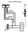
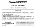
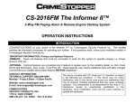
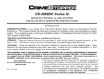
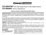
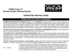
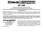
CS-870RKE
REMOTE KEYLESS ENTRY SYSTEM
INSTALLATION & OPERATING INSTRUCTIONS
INTRODUCTION:
CONGRATULATIONS on your choice of a Remote Keyless Entry System by Crimestopper Security Products
Inc. This booklet contains the information necessary for installing, and operating your system. If any
questions arise, contact your installation dealer or Crimestopper Security Products Inc. at the Tech Support
number below.
*IMPORTANT INFORMATION: Primary and Optional Features
-PRIMARY FEATURES: These are features that must be connected in order for the system to operate
properly i.e. Power & Ground, along with the Primary features of Power Locks & Flashing Lights.
-OPTIONAL FEATURES: Optional features are connected only if desired or agreed upon by the installing
dealer i.e. Horn Chirp and Trunk Pop. These features may require additional parts and labor charges. Consult
with your installer and come to an agreement about your optional features before installation. NOTE: The LED
is required for programmable options.
TECH SUPPORT
Mon-Fri 8:00 AM-4:30 PM Pacific Time
(800) 998-6880
www.crimestopper.com
[email protected]
REV. 01.2009
This device complies with FCC Rules part 15. Operation is subject to the
following two conditions: 1) This device may not cause interference, and (2)
this device must accept any interference that may be received, including
interference that may cause undesired operation. The manufacturer is not
responsible for any radio or TV interference caused by unauthorized
modification to this equipment. Such modification could void the user's
authority to operate the equipment.
TABLE OF CONTENTS
Pre-Installation & Component Mounting……………………..…………………………………………………2-3
Wiring……..……………………………………………………………………………………………………..…….3-4
Power Door Lock Wiring……………………………………………………….………..……………….…...……4-5
Negative Trigger Door Locks………………………….……………………...…......………………………………6
Positive Trigger Door Locks………..………………………….…………………………….…………......……….7
5-Wire Reverse Polarity Trigger Door Locks ………………………….…………………………….…………..8
After Market Door Locks…………….……………………………......................................................................9
1-Wire Door Locks……..……………………………………...………………………………………….……….10-12
Wiring Diagram………………………………………………………………………………………………..………13
Transmitter Programming………………………………………………………………………………..…………14
Operating Instructions………………………..…………………………………………………………..………....15
PRE-INSTALLATION CONSIDERATIONS
BEFORE BEGINNING, check all vehicle manufacturer cautions and warnings regarding electrical service (AIR
BAGS, ABS BRAKES, ENGINE / BODY COMPUTER AND BATTERY).
PLAN OUT YOUR INSTALLATION and determine most suitable locations for all components to be placed.
These components include: the module itself, valet/program button and possible relays. Allow enough wire to
create a service loop with strain relief, should servicing be required.
DAMAGE resulting from incorrect installation or failure to follow guidelines stated in this book will not be
covered under warranty and subject to repair or replacement charges.
USE A VOLT/OHM METER to test and locate all connections. Test Lights can damage a vehicle’s computer
systems.
DO NOT ROUTE ANY WIRING THAT MAY BECOME ENTANGLED with brake, and gas pedals, steering
column, or any other moving parts in the vehicle.
2
COMPONENT MOUNTING
CONTROL MODULE: Locate the module underdash as high as possible. Driver’s Side usually provides an
easy location for the majority of the wiring connections. The antenna wire should be routed away from any
metal if possible. DO NOT alter the length of the antenna wire, or ground the antenna wire.
PROGRAM BUTTON: Mount the button in a hidden but accessible location. It is used for programming new
remote controls.
LED (Optional): The optional Red LED provides a useful theft deterrent. The LED blinks after you lock the
vehicle with your remote simulating an alarm system. The LED is also used when programming remotes. If
you decide to install the LED, choose a visible location in the dash or console for a location.
WIRING
YELLOW WIRE: IGNITION SWITCHED “ON” AND “START” +12 VOLTS
Connect to an ignition wire that shows +12 Volts when the key in both “On” and “Start” positions.
BROWN/BLACK: (-) HORN HONK/CHIRP OUTPUT (Optional, requires relay)
This wire provides a negative pulse output to honk/chirp the factory horn for audible lock/unlock confirmation.
Connect Brown/White to terminal 86 of a relay. Connect terminal 85 to +12V Constant. Connect terminal 87
to +12V or GROUND depending on the type of horn activation circuit in the vehicle. Connect terminal 30 to
the horn activation circuit. NOTE: Many vehicles use a Negative type of horn circuit, however we recommend
that you test the circuit on your vehicle before making any connections to avoid any possible damage.
BLACK WIRE: SYSTEM CHASSIS GROUND
THIS WIRE MUST BE CONNECTED TO CHASSIS METAL OF THE VEHICLE. Scrape away any paint or dirt
from the connection point to ensure a good connection. Keep ground wire short.
GRAY WIRE: (-) AUXILIARY REMOTE OUTPUT 1 (Optional, requires relay)
Negative Pulsed output controlled by pressing Button #3 (Trunk Symbol) for at least 1 second.
3
WIRING
WHITE WIRE: +12Volt PARKING LIGHT (On-Board Relay 10A)
A) For Domestic Cars Signal Circuit: Cut 2 Diodes from White wire. Connect fused White wire to switched
+12V parking light wire at back of light switch. If this is not possible, connect directly to one of the
parking lights at the front of the vehicle.
B) For European vehicles with separate right and left circuits: Use the 2 diodes as shown to separate the
output signal.
RED WIRE: +12V POWER INPUT (15 amp fuse)
Connect to +12 Volt source with supplied fuse & holder. Recommended location for this connection is at the
vehicle battery positive terminal.
POWER DOOR LOCK WIRING:
DETERMINING DOOR LOCK TYPE:
We recommend determining the type of locking system the vehicle has before connecting any wires. Incorrect
connection may result in damage to the alarm and/or vehicle locking system. Door lock information is
provided as a guide. Your vehicle may differ.
LOCK RELAY: (On-Board Relay)
WHITE/BLACK: Normally Closed (Terminal 87A On-board Lock Relay)
GREEN: LOCK Output (Terminal 30 On-board Lock Relay)
VIOLET/BLACK (Fused 10A): Normally Open (Terminal 87 On-board Lock Relay)
UNLOCK (On-Board Relay):
BROWN: Normally Closed (Terminal 87A On-board Unlock Relay)
BLUE: UNLOCK Output (Terminal 30 On-board Unlock Relay)
VIOLET (Fused 10A): Normally Open (Terminal 87 On-board Unlock Relay)
4
POWER DOOR LOCK WIRING:
Negative Trigger (-):
Many Imports; Late model Ford & General Motors
Negative trigger door lock systems send a Negative (Ground) pulse to existing factory relays to lock and
unlock the vehicle doors.
Positive Trigger (+):
Many General Motors; Chrysler / Dodge / Plymouth
Positive trigger door lock systems send a Positive (12V) pulse to existing factory relays to lock and unlock the
vehicle doors.
Reverse Polarity: Many Ford/Lincoln/Mercury/Dodge/Chrysler/Plymouth and early 90’s GM Trucks
Reverse Polarity systems use no relays, but instead the door lock/unlock motors are controlled directly from
the lock and unlock switches in the door. The lock and unlock wires rest at Negative Ground when not in use.
When the lock or unlock button is pressed, one of the circuits is “Lifted” and replaced with +12V causing a lock
or unlock to occur.
Single Wire (Dual Voltage): Late model Chrysler/Dodge/Plymouth Vehicles, some 2000-UP GM Cars
Dual Voltage systems have lock/unlock switches that send varying levels of Positive voltage OR Negative
ground current to the SAME wire for both lock and unlock. When the vehicle’s Body Computer Module (BCM)
or door lock module senses different voltages on this wire, the system will either lock or unlock. Single wire
door lock systems require resistors.
Databus Systems 2000-UP GM Cars, 2003-UP GM Trucks & SUV’s, ’96-UP Jeep and Chrysler
Databus systems send low current “Data messages” to the door lock controllers on a network in order to lock
and unlock the vehicle. To install aftermarket systems in these vehicles, an interface module is required that
converts the regular lock/unlock pulses into “Data messages” to allow locking & unlocking. Interface modules
are sold separately.
5
NEGATIVE TRIGGER DOOR LOCK WIRING
Lock Outputs
White/Black (N.C.)
Green
Violet/Black
Unlock Outputs
Brown (N.C.)
Blue
Violet
Ground
Factory
Door
Lock
Module
L
U
Ground
6
POSITIVE TRIGGER DOOR LOCK WIRING
Lock Outputs
White/Black (N.C.)
Green
Violet/Black
Unlock Outputs
Brown (N.C.)
Blue
Violet
+
12 Volts
L
U
+
12 Volts
7
Factory
Door
Lock
Module
5 WIRE REVERSE POLARITY DOOR LOCK WIRING
Lock Outputs Lock Outputs
White/Black
Green
Violet/Black
Unlock Outputs
Brown
Blue
Violet
+
12 Volts
L
+
cut
U
cut
8
AFTER MARKET DOOR LOCK WIRING
Lock Outputs
White/Black
Green
Violet/Black
Unlock Outputs
Brown
Blue
Violet
Ground
+
12 Volts
9
1-WIRE RESISTOR DOOR LOCKS
Single Wire (Dual Voltage): Late model Chrysler/Dodge/Plymouth Vehicles, some 2000-UP GM Cars
Dual Voltage systems have lock/unlock switches that send varying levels of Positive voltage OR Negative
ground current to the SAME wire for both lock and unlock. When the vehicle’s Body Computer Module (BCM)
or door lock module senses different voltages on this wire, the system will either lock or unlock. Single wire
door lock systems require resistors.
1. Locate your vehicle in the chart below to determine the proper resistor value(s), wire color and location.
Note: the information is intended as a guide and your vehicle may differ.
2. See chart below for installation.
Polarity
Lock
Resistor
Unlock
Resistor
Wire Color
Location
Buick Rendezvous 2001-UP
Chevy Malibu 2001-UP
Chevy Impala, Monte Carlo 2000-UP
Neg.
Neg.
Neg.
470 Ohms
None
470 Ohms
None
1.5K Ohms
None
Red / Black
White
Orange / Black
Chrysler 300M, Concord, Intrepid, LHS, 1998-UP
Pos.
2.7K Ohms
620 Ohms
White / Green
Chrysler 300C
Chrysler Pacifica
Chrysler PT Cruiser 2001-2006
Chrysler PT Cruiser 2001-2006 with alarm
Neg.
Neg.
Neg.
Neg.
330 Ohm
1.8K Ohm
None
2.7K Ohms
100 Ohm
750 Ohm
1.5K Ohms
7.5K Ohms
Chrysler PT Cruiser 2007-UP
Neg.
None
250 Ohms
Pos.
900 Ohm
430 Ohm
Violet / Green
Violet / Blue
White / Green
White / Green
LT Green/
DK Green
LT Green/
Orange
BCM at Console
Driver’s Kickpanel
Driver’s Kickpanel
BCM at Driver’s
Kickpanel
Driver’s Kickpanel
Inside Driver’s Door
Driver’s Kickpanel
Driver’s Kickpanel
Pos.
620 Ohms
2.7K Ohms
White / Green
Pos.
620 Ohms
2.7K Ohms
White / Green
Pos.
750 Ohms
1.8K Ohms
LT Green/
Orange
Pos.
1780 Ohms
730K Ohms
White / Green
Pos.
1780 Ohms
730K Ohms
LT Green/
Orange
BCM at Driver’s
Kickpanel
BCM at Driver’s
Kickpanel
BCM at Driver’s
Kickpanel
BCM at Driver’s
Kickpanel
BCM at Driver’s
Kickpanel
Neg.
1.5K Ohms
250 Ohms
White / Green
Driver’s Kickpanel
Vehicle
Chrysler 1995-00 Cirrus, Stratus, Sebring Cont,
with alarm
Chrysler 1995-00 Cirrus, Stratus, Sebring Cont
without alarm
Chrysler Sebring and Stratus coupe 2001 without
alarm
Chrysler Sebring and Stratus coupe 2001 with
alarm
Chrysler Sebring and Stratus sedan 2001 without
alarm
Chrysler Sebring and Stratus sedan 2001 with
alarm
Chrysler Town & Country 1996-2000 without
alarm
10
Driver’s Kickpanel
Driver’s Kickpanel
Chrysler Town & Country 1996-2000 with alarm
Chrysler Town & Country 2001-06 without alarm
Chrysler Town & Country 2001-06 with alarm
Chrysler Voyager 2001-2006
Dodge Caravan 1996-2000 without alarm
Dodge Caravan 1996-2000 with alarm
Dodge Caravan 2001-06 without alarm
Dodge Caravan 2001-06 with alarm
Dodge Charger
Neg.
Neg.
Neg.
Neg.
Neg.
Neg.
Neg.
Neg.
Neg.
4020 Ohms
5.2K Ohms
2K Ohms
5.3K Ohms
1.5K Ohms
4020 Ohms
5.2K Ohms
2K Ohms
330 Ohm
665 Ohms
2K Ohms
5.2K Ohms
2K Ohms
250 Ohms
665 Ohms
2K Ohms
5.2K Ohms
100 Ohm
Dodge Durango 2000
Neg.
620 Ohms
1.5K Ohms
Dodge Durango 2001-02 without alarm
Dodge Durango 2001-02 with alarm
Dodge Magnum
Dodge Neon 2000-UP without alarm
Dodge Neon 2000-UP with alarm
Dodge Ram Pickup 2002 without alarm
Neg.
Neg.
Neg.
Neg.
Neg.
Neg.
815 Ohms
620 Ohms
330 Ohm
None
2.7K Ohms
815 Ohms
315 Ohms
1.5K Ohms
100 Ohm
1.5K Ohms
750 Ohms
315 Ohms
Dodge Ram Pickup 2002 with alarm
Neg.
2K Ohms
480 Ohms
Dodge Ram Pickup 2004
Ford Probe 1990-97
Ford Escape 2001-UP
Jeep Liberty 2002-UP
Mazda 323 1995
Mazda 626 1998-01
Mazda Millennia 1995-99
Mazda Millennia 2001
Mazda MPV 2000 without alarm
Mazda MPV 2000 with alarm
Mazda Protégé 1998-03
Mazda Tribute 2001-UP
Mercedes Benz SLK230 98-01
Oldsmobile Alero 1999-UP
Plymouth Breeze 1996-00
Plymouth Voyager 1996-2000 without alarm
Plymouth Voyager 1996-2000 with alarm
Pontiac Aztec 2001-UP
Pontiac Grand Am 1999-UP
Neg.
Pos.
Neg.
Neg.
Neg.
Neg.
Neg.
Neg.
Neg.
Neg.
Neg.
Neg.
Neg.
Neg.
Pos.
Neg.
Neg.
Neg.
Neg.
880 Ohms
None
1K Ohm
1.4K Ohm
1K Ohms
1K Ohms
1K Ohms
1K Ohms
2.2K Ohms
2.2K Ohms
1K Ohms
1K Ohm
526 Ohms
None
620 Ohms
1.5K Ohms
4020 Ohms
470 Ohms
None
280 Ohms
4.7K
None
440 Ohm
None
None
None
None
None
None
None
None
None
1.5K Ohms
2.7K Ohms
249 Ohms
665 Ohms
None
1.5K Ohms
11
White / Green
Violet / Green
Violet / Blue
White / Green
White / Green
White / Green
Violet / Green
Violet / Blue
Violet / Green
LT Green
/Orange
White / Green
White / Orange
Violet / Green
LT Green
LT Green
White / Green
LT Green/
Orange
Violet / LT Blue
Green / Black
Pink / White
Pink / Violet
White / Blue
Yellow / Green
Red / Black
White/Blue
DK Green
LT Green
Green / Red
Pink / White
White / Green
White
White / Green
White / Green
White / Green
Red / Black
White
Driver’s Kickpanel
BCM at Firewall
BCM at Firewall
Driver’s Kickpanel
Driver’s Kickpanel
Driver’s Kickpanel
BCM at Firewall
BCM at Firewall
Driver’s Kickpanel
Driver’s Kickpanel
Driver’s Kickpanel
Driver’s Kickpanel
Driver’s Kickpanel
Driver’s Kickpanel
Driver’s Kickpanel
Driver’s Kickpanel
Driver’s Kickpanel
Driver’s Kickpanel
Driver’s Kickpanel
Driver’s Kickpanel
Driver’s Kickpanel
Driver’s Kickpanel
Driver’s Kickpanel
Driver’s Kickpanel
Driver’s Kickpanel
Pass Kickpanel
Pass Kickpanel
Driver’s Kickpanel
Driver’s Kickpanel
Driver’s Kickpanel
Driver’s Kickpanel
Driver’s Kickpanel
Driver’s Kickpanel
Driver’s Kickpanel
BCM at Console
Driver’s Kickpanel
1-WIRE RESISTOR DOOR LOCKS
Lock Outputs
White/Black (N.C.)
Green
Violet/Black
Unlock Outputs
Brown (N.C.)
Blue
Violet
Ground
¼ Watt
Resistor
Factory
Door
Lock
Module
L
U
12
SYSTEM WIRING DIAGRAM
Antenna Wire
CS-870 RKE
Jumper for Door Locks
OFF = 0.75 Seconds
ON = 3 seconds
Ignition
PROGRAM
SWITCH
Yellow
Brown/Black
STATUS
LED
+
86 30
87A
85 87
Factory Car Horn
(-)
(+)
15 AMP
FUSE
Black
Red
Ground
12 Volt
Battery
Lock Outputs
White/Black
Green
Violet/Black
10 AMP
FUSE
(+) Parking Lights
Normorlly Closed
Common
Normally Open
White
Unlock Outputs
Aux 1
Trunk Pop Relay
30 86
87A
87 85
Brown
Blue
Violet
Gray
+
13
Normorlly Closed
Common
Normally Open
TRANSMITTER PROGRAMMING
1. Turn Ignition ON.
2. Press the Program/Override Button 4 times. After a few second delay, the unit will chirp and flash the
lights 4 times.
3. Press button 1 on the remote control you wish to learn. You will get 2 Horn chirps and light flashes
indicating the unit is waiting for a 2nd code, then press button #1 of a second transmitter or transceiver,
the unit will chirp and flash the lights 3 times indicating its waiting for the 3rd code and 4 times. If all 3
codes are learned, the unit will automatically exit code-learning mode, otherwise turn key off to exit
programming mode.
Note 1: All transmitter codes must be learned at the time of programming. Any transmitters not present will
be dropped from system memory. This system will learn a total of 3 transmitters max.
TURN IGN ON
IGN
OFF
PRESS PROGRAM
WAIT FOR
4 FLASHES
4 TIMES
IGN
ANIC
OFF
FLASH 2, 3, or 4 X's
PRESS BUTTON #1
ON EACH REMOTE
14
OPERATION
REMOTE LOCK
To lock the doors, press the Lock Symbol (Button #1) on the
transmitter. Lights will flash once and LED will begin flashing.
You will also hear a single horn chirp (if optional horn chirp
feature is installed).
REMOTE UNLOCK
To unlock the doors, press the Unlock Symbol (Button #2) on
the transmitter. Lights will flash 2 times. You will hear 2 horn
chirps (if horn chirp installed).
#2
#1
UNLOCK
LOCK
#3
#4
ANIC
PANIC
TRUNK
REREASE
REMOTE PANIC PROTECTION
(OPTIONAL, REQUIRES HORN HONK FEATURE)
To sound the Panic Alarm in an emergency, press and hold the Panic
Symbol (Button #3) for at least 2 seconds. The horn will begin to pulse
and parking lights will flash for up 30 seconds or until the Panic Button on
the transmitter is pressed again to reset this mode.
TRUNK / HATCH POP (OPTIONAL)
To pop the trunk (Optional), press the Trunk Symbol (Button #4) on the transmitter for at least 2 seconds.
There is a slight delay on this function. This is an intentional delay to help prevent your trunk or hatch from
opening accidentally when the remote is in your pocket or purse.
CAR FINDER MODE
To activate Car Finder Mode, press the Lock Button after the doors are already locked. The Lights will flash 3
times and the Horn will honk 3 times
15
www.crimestopper.com
[email protected]
Phone (800) 998-6880
FAX (805) 581-9500
ONLINE TECHNICAL SUPPORT
www.crimestopper.com/techweb03.html
© 2009 Crimestopper Security Products
16