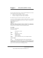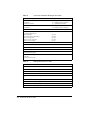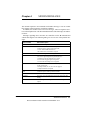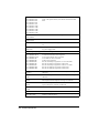
1
LC 144 VF HIGH SPEED MODEM for • • Data Transmission • • Fax • • Speech Messages User Manual CREATIX Polymedia GmbH Fasanerieweg 15 66121 Saarbrücken Dieses Dokument wurde erstellt mit FrameMaker 4.0.4. CREATIX Polymedia GmbH, Saarbrücken 1994 This handbook is protected by copyright. It must not be copied, reproduced, translated or transmitted in electronic media, in whole or in part. Accuracy of the information is not guaranteed. Any mention in this handbook of products made by other manufacturers is for information purposes only and represents no misuse of trademarks. jüt mv205a0.133e Table of contents Chapter 1 INTRODUCTION 1-1 What is a Modem ? 1-1 About this Modem 1-1 Special Features 1-2 General Description 1-2 Installation Instructions 1-2 Basic Adjustments 1-3 Chapter 2 AT COMMANDS: DATA MODEM 2-1 Guidelines for Using AT Commands 2-1 AT - Attention Code 2-4 The ESC Sequence 2-4 A - Answer Mode 2-4 A/ - Repeat Last Command Line 2-5 B - BELL/CCITT Standard 2-5 D - Automatic Dialling and Dialling Parameters 2-5 E – Echo Function 2-6 F – Determining Type of Modulation and Speed 2-6 H – Switch Hook Check (Replace Handset) 2-7 I – Firmware Information 2-7 L – Volume Level of Connected Loudspeaker 2-7 M – Switching the Loudspeaker On and Off 2-7 N – Recognizing Type of Modulation 2-7 O – Return to On-Line Operation 2-8 P – Selecting Pulse Dialling 2-8 Q – Modem Messages On / Off 2-8 S – Reading and Modifying Registers: 2-8 T – Selecting Tone Dialling 2-8 V – Verbal or Numeric Modem Messages 2-8 W – Controlling Connect Messages 2-8 X – Extended Connect Messages; Making Connections Y – Long Space Disconnect 2-9 2-9 I Dieses Dokument wurde erstellt mit FrameMaker 4.0.4. Z – Reset/Load a Stored Profile 2-10 &C – M5 Control Line 2-10 &F – Loading the Factory Settings 2-10 &G – Guard Tone 2-11 &K – Flow Check 2-11 &M – Asynchronous Dialling / Synchronous Data Transmission &Q – Synchronous / Asynchronous 2-11 &R – Control Lines S2 and M2 2-12 &S – Control Line M1 (107/DSR) 2-12 &T – Modem Test Functions 2-12 &V – Displaying the Current Configuration 2-13 &W – Storing a set Profile 2-13 &X – Setting the Clock Signal in Synchronous Mode 2-14 &Y – Selecting a Start Configuration 2-14 &Z – Telephone Number Storage 2-14 \A – Maximum MNP Block Size 2-14 \B – Sending a Break Signal 2-14 \F – Displaying the Telephone Number Store 2-15 \G – Modem/Modem Flow Check 2-15 \J – Baud rate Adjustment via the Computer 2-15 \K – Type of Break Control 2-16 \L – Determining Block/Stream Mode with MNP 2-16 \N – Data Transmission Mode 2-16 \S – Displaying the Configuration 2-17 \W – Split Speed Operation 2-17 -K – Extended MNP Operation 2-17 %C – Authorise Data Compression 2-18 %E – Automatic Retrain 2-18 %F – 75Tx/1200Rx or 1200Tx/75Rx in V.23 Mode 2-18 *H – Handshake Speed with MNP 10 Modem: 2-18 *C – Password for Remote Configuration 2-18 *R – Remote Configuration 2-19 *E – End Remote Configuration 2-19 *P – Password for Automatic Callback 2-19 *L – Displaying Callback Numbers 2-20 II 2-11 Chapter 3 DIALLING WITH V.25.Bis Chapter 4 MODEM MESSAGES Chapter 5 S-REGISTERS 3-1 4-1 5-1 S0 – Number of Ring Characters before Modem engages 5-2 S1 – Ring Character Counter 5-2 S2 – Esc Sequence Character 5-2 S3 – Carriage Return Character 5-2 S4 – Line Feed Character 5-2 S5 – Backspace Character 5-3 S6 – Waiting Time for Dialling Tone 5-3 S7 – Waiting for Carrier Signal 5-3 S8 – Pause Time after Comma 5-3 S9 – Answer Time after Carrier Recognition 5-3 S10 – Delay between Carrier Loss and Hanging Up 5-4 S12 – Guard Time for Esc Sequence 5-4 S14 – General Options 5-4 S16 – Modem Test Options 5-5 S18 – Test Timer 5-5 S19 – Autosync Register 5-6 S20 – HDLC Address/BSC Synchronous Character 5-6 S21 – V.24/General Options 5-6 S22 – Loudspeaker/Authorised Modem Messages 5-7 S23 – General Options 5-7 S24 – Current Saving Switch 5-8 S25 – DTR Delay Time 5-8 S26 – Delay RTS to CTS 5-8 S27 – General Options 5-8 S28 – General Options 5-9 S29 – Flash Dial Modifier Time 5-9 S30 – Inactivity Timer 5-9 S31 – General Options 5-10 S32 – XON Character 5-10 S33 – XOFF Character 5-10 S36 – Fallback on V.42 Connection Set-up 5-10 III S37 – Speed on the Telephone Line 5-11 S38 – Delay before Hanging Up 5-11 S39 – Flow Control 5-11 S40 – General Options 5-12 S41 – General Options 5-12 S46 – Authorising a Data Compression 5-13 S48 – Directing the V.42 Handshake 5-13 S80 – Soft Switches 5-13 S82 – Treating the Break Signal 5-13 S86 – Error Codes for NO CARRIER Messages S95 – Extended Connection Messages 5-14 TECHNICAL INFORMATION A-1 Digital Interfaces A-1 Audio Jack A-1 LED Indicators A-2 GLOSSARY A-2 CCITT RECOMMENDATIONS Technical Specifications A-4 IV A-3 5-14 Chapter 1 INTRODUCTION The Data Modem you have purchased represents the latest state of the art in data communication; its comprehensive facilities provide all you will need for professional data transfer purposes. In data modem mode, you can achieve active transfer speeds of up to 57 600 bps and up to 14 400 bps in fax mode. This handbook, together with the descriptive information provided with your communications software, gives all the information you need to install and operate the equipment. What is a Modem? The word “Modem” is derived from the terms “MOD-ulator” and “DE-modulator”. Putting it more simply, it is a device which modulates digital information into an analogue carrier signal (tones) and demodulates the carrier signals which it receives, changing them back into digital data. This permits the transmission of data along wires, between data terminal equipment (computers, terminals, etc…). About this Modem This modem operates as a full duplex, voice-band modem, where signal transmissions are made in both directions simultaneously and the analogue signals which are transmitted are in the voice-band of the telephone network - between 300 and 3000 Hz. Data transmission between modem and terminal unit is in serial form - in other words, the individual data bits are sent, one after another, along a single transmission or receiving line. At this stage, a word of explanation regarding synchronous and asynchronous data transmission. In the synchronous mode, additional synchronisation signals are required, to synchronize the transmission and reception signals. In the asynchronous mode synchronisation is by means of “start-bits” and “stop-bits” which mark the beginning and end of each data word. The modem can dial by itself and also react automatically to incoming calls. The information it needs in order to dial a telephone number, together with the various configuration commands, are provided by the respective data terminal equipment via the same serial interface which is used to send the data. In this mode, the system operates with the so-called “AT” command set or to V.25bis. INTRODUCTION 1-1 Dieses Dokument wurde erstellt mit FrameMaker 4.0.4. Special Features Fax Transmission and Reception at up to 14 400 bps • • Automatic recall of Stored Telephone Numbers, with • Password Protection • Remote Configuration • Number Storage for 20 Telephone Numbers • Voice Mode for Onward Transfer of Voice • Information (Option) • Compression/Decompression of digitized speech General Description Synchronous or Asynchronous • • Auto-protocol: the Modem adjusts automatically to all Full Duplex Trans• • • • • • • mission Protocols and Speeds MNP 5 and V.42bis Data Compression and Error Correction MNP 10; specially useful in association with Radio Telephones Max. 57 600 bps Active Transmission Rate (V.32bis with V.42bis) Automatic Baud Rate Recognition at all Speeds up to 57 600 bps in Hayes Mode Automatic Dialling with Hayes AT Command Set or with V.25bis Automatic Recall with Password Protection Remote Configuration is possible over Telephone Line Installation Instructions 1. Use the interface cable supplied to connect the modem to a free COM interface on the computer 2. Use the telephone cable supplied to connect the modem to a Telephone jack 3. Use the mains cable supplied to connect the modem to a power socket (220-240 VAC) 4. When the “POWER” LED is lit, the modem is ready for operation and will provide data communication, using the factory settings which have been installed 5. Configure the modem with the communications software or fax software to meet your requirements ➮ Voice Mode is available only with the appropriate Accessory Pack 1-2 INTRODUCTION Basic Adjustments To make it easier for you to use your modem, two basic settings have been made at the factory, which are suitable for the vast majority of connection systems. These settings can be activated with the “&F” command. In the fax mode or voice mode, the relevant software will carry out control of modem settings for you. • for BTX Operation (Datex-J with 2400 bps), select AT&F1 in the software as the initialisation sequence • For general Remote Data Transmissions select AT&F0. In this condition, the modem will attempt to create an error-corrected connection with data compression, depending on the capability of the other party Loudspeaker/Headphones Microphone Volume Control POWER ONLINE LEDs DSR DCD CTS RTS DTR COM Interface Power Supply What the LED Indicators mean: • • • • POWER ONLINE DSR DCD • • • CTS RTS DTR ➮ Ensure that the correct COM interface is used for the software employed ! Modem is ready for operation Modem is switched to the transmission line Answer tone is present Modem has recognized the carrier tone from the remote modem Modem is ready to transmit Transmission request is present Computer is ready for operation INTRODUCTION 1-3 1-4 INTRODUCTION Chapter 2 AT COMMANDS: DATA MODEM Guidelines for Using AT Commands The modem is programmed with AT commands from the data terminal equipment (computer, PC or terminal) and thus also receives instructions to cover automatic dialling. The communications or fax software (Voice Software as an option) will carry out most of these operations for you, so that in general circumstances you do not need to have a detailed understanding of the commands which are described below. The modem must be in Command mode before it can accept commands. In this condition, all the characters sent from the computer are interpreted as commands and, where appropriate, confirmed by a modem message on the screen. When a connection is set up to a remote modem, the modem will switch to data mode and transfer all the characters it receives to the other party. The modem can be switched from an existing connection, back into the command mode, by using the Esc Sequence (+++), without breaking off the connection to the remote modem. In this status, any commands which are entered will not be transferred to the remote modem. The modem is activated by AT commands, the subsequent value of which will modify the form of the command. Modem messages provide information on the form of the commands. In the Hayes Command Set, commands are entered by the character sequence AT (at) and can also be entered as a list of commands with or without spaces between the individual commands. The “Backspace” key is used for deleting. Commands can be entered in upper-case or lower-case. In the command mode, the modem automatically recognizes data frames and data speed. ➮ AT commands can be transferred to the modem at the following data speeds: 57600, 38400, 19200, 14400, 9600, 4800, 2400, 1200, 600 and 300 bps Examples of Command Syntax: ATX1<CR> ATQ0<CR> ATDP12345<CR> Individual commands ending with the <CR> Enter key, can be entered in a different manner with the same effect, by inserting as many spaces as you need, to make the command easier to visualise ATX1QODP12345<CR> or: AT X1 Q0 DP 12345<CR> AT COMMANDS: DATA MODEM 2-1 Dieses Dokument wurde erstellt mit FrameMaker 4.0.4. Table 1 Modem Commands Standard Commands ATA A/ ATB ATD ATE ATF ATH ATI ATL ATM ATO ATP ATQ ATS ATT ATV ATW ATX ATY ATZ +++ AT&C AT&F AT&G AT&K AT&M AT&Q AT&R AT&S AT&T AT&V AT&W AT&X AT&Y AT&Z Answer mode: Modem monitors telephone line Repeat last command line; entered without “AT” Switching between BELL/CCITT Standards at 300 or 1200 bps Enter automatic dialling Controlling repeat of modem commands on screen Determine type of modulation and speed Break off an existing connection Information on Modem product code Loudspeaker volume control Switch on loudspeaker Return to Online-mode after entering Esc sequence Select Pulse dialling Controlling modem messages Read and modify modem register(s) Select Tone dialling Modem message format (verbal or numeric) Directing speed messages Modem function during dialling; modem messages Long Space Disconnect Modem Reset and Load one of the stored modem profiles Escape Sequence to return temporarily to Command mode Controlling M5 (DCD) Signal at the serial interface Load the factory setting Switch on a Guard Tone Flow Check Synchronous data transmission with asynchronous dialling Authorised types of connection Controlling M2 (CTS) and S2 (RTS) Signal at the serial interface Controlling M1 (DSR) Signal at the serial interface Modem test functions Displaying current configuration Storing Modem settings Directing the Clock Signal Selecting the configuration which will be active after modem start Storing telephone numbers 2-2 AT COMMANDS: DATA MODEM Extended MNP- and V.42bis-Commands AT\A Determining Data Block Size with MNP operation AT\B Sending a Break signal to the remote modem AT\F Display stored telephone numbers AT\G Modem-modem flow check (XON/XOFF) AT\J Adjusting computer/modem speed to the modem/modem speed AT\K Effects of the Break Signal AT\L MNP Block/Stream mode AT\N Switching between Direct, Normal and MNP modes AT\S Displaying current modem configuration on screen AT\W Authorise V.23 operation AT\U Accept an MNP connection in a Normal connection AT\V Information content of MNP connection messages AT\X Transfer XON/XOFF control characters to the remote modem AT\Y Switch to error-free connection from Normal connection AT\Z Switch to Normal connection from an error-free connection AT%C Controlling Error correction and Data compression AT%E Authorise data compression AT%F Dialling 75Tx/1200Rx or 1200Tx/75Rx AT*C Storing password for remote configuration AT*E Ending remote configuration AT*H Handshake speed between MNP 10 modems AT*L Displaying Directory for callbacks protected by password AT*P Storing passwords for automatic callback AT*R Interrogating for remote configuration AT-K Authorising extended MNP Class 10 Other Commands V.25bis Commands CIC Modem goes in Answer mode on to line CRI Dialling command with optional identification CRN Dialling command CRS Dialling a stored dialling string DIC Ignore incoming call PRI Store programme identification PRN Store dialling strings RLN Displaying stored telephone numbers (dialling strings) AT COMMANDS: DATA MODEM 2-3 AT - Attention Code The AT (Attention) Code, which introduces each command line, can be entered in upper-case or lower-case characters. Several commands (separated by spaces if desired) can be positioned one after another, in one line. A command line must end with the ASCII character which is stored in the S3 or S4 Register (or with both together). The standard value for S3 is Carriage Return (<CR>=13 decimal) and Line Feed (<LF>=10 decimal) for S4. A command line without <CR>,<LF> will remain in the command buffer until <CR>,<LF> is entered, or until the action is broken off with <Cntrl-X>. Once <CR>,<LF> has been received, the modem carries out the commands following the AT and answers with an appropriate modem message. The maximum length of a command line is 40 characters. If the capacity of the command buffer is exceeded, the modem issues an Error message. ➮ The AT code enables the modem to recognize the speed, parity and characterlength of the communication programme The ESC Sequence If the modem has established a data connection, you can enter more commands at any time, without breaking off the connection. This is achieved by sending three ASCII characters (S2 Register) from the computer to the modem. The standard setting is the “+” character. In order for this to be interpreted as the ESC sequence, certain time limits must be observed in entering the plus-characters. Before the first and after the last character, a Guard time is required (the standard is 1 second) and the individual characters must not be separated from each other by longer than this time period. A - Answer Mode When the A command is entered, the modem switches to the “Off-Hook” condition in the Answer mode and takes over control of the telephone line connected. In this way, the modem transmits in the upper frequency band (upper channel) If further commands are entered after the A command before a connection has been made, the modem interrupts the establishment of a connection, switches to command mode and issues a NO CARRIER message. If no carrier is received from the remote station after the waiting time which is set in the S7 Register, the modem responds with a NO CARRIER message and returns to command mode. If the modem does receive the carrier signal, it issues a CONNECT message and switches to Data mode. ➮ If the handset is not replaced after the data transmission has been completed, the connection remains made and you will continue to pay for this ! 2-4 AT COMMANDS: DATA MODEM A/ - Repeat Last Command Line The A/ command causes the modem to repeat the command line which is stored in the command buffer, e.g. it will dial again, if the line is busy. This command is entered without AT and no reply is issued. ➮ A command line remains until the modem receives a new command. The data format should not be modified in the meantime. B - BELL/CCITT Standard The B command permits change-over between CCITT and Bell standards at 300 or 1200 bps. At 300 bps, this command will select between Bell 103 and CCITT V.21, while at 1200 bps it will select between Bell 212A and CCITT V.22. ATB0 CCITT V.22, V.21 (factory setting) ATB1 Bell 212A, Bell 103 ➮ The B command refers only to connections at 300 or 1200 bps. All other speeds use the CCITT standard. D - Automatic Dialling and Dialling Parameters The D command instructs the modem to go on-line and to dial. If this command is entered without parameters, the modem will go on-line in Originate mode. The following characters are authorised in the dialling sequence: 0-9 The digits of the telephone number P, T In the Dial command, these parameters switch to pulse-dialling (P) or to tone-dialling (T) until the other parameter is entered. The standard setting is pulse-dialling. W Dialling tone recognition. When this parameter is entered, the modem will not continue dial until it has recognized the sign that the line is free. This is an advantage in branch exchanges, where it is not always possible to guarantee immediate access to a line. , Dialling pause (1 sec). This comand may not be used in the dialling sequence when the modem is supposed to wait for a new dialtone. The W-parameter must be used in this case. A-D,*,# Additional characters when tone-dialling S=n Dialling number which is stored with &Zn ! Call exchange by Flash ^ Switch off calling tone; this applies only during the current dialling process ;H Modem as automatic dialling device. Here, the dialling sequence is terminated by a semi-colon, followed by the H command. The modem goes off-line after dialling and you can take over the conversation using a telephone. The handset must be lifted during the dialling process. AT COMMANDS: DATA MODEM 2-5 Example of how to set up a Dial Command ATD T0 , P 02212971 With this, a private automatic branch exchange using tone-dialling dials zero, in order to obtain an exchange line. The modem then waits one second for the “line-free” tone so that it can dial the rest of the telephone number in pulse-dialling mode Example of the Automatic Dialling Function ATD T0 , P 02212971;H If you lift the handset during the dialling process, you can take over the connection yourself. ➮ Where appropriate, ask the manufacturer of your private automatic branch exchange what specific features need to be taken into account in the dialling procedure ➮ If the handset is not replaced after the data transmission has been completed, the connection remains made and you will continue to pay for this ! E – Echo Function The E command determines whether the modem will issue an echo of the command which is entered. ATE0 No command echoes are issued to the computer ATE1 Command echoes are issued (factory setting) F – Determining Type of Modulation and Speed The parameter of this command determines the type of modulation. It operates in conjunction with the N command and the S37 Register. ATF0 Automatic recognition of the remote modem's capabilities. Connections with all possible speeds are authorised. The S37 value and interface speed are ignored. ATF1 V.21 or Bell 103 (according to the B command) ATF3 V.23 (send 75 bps, receive 1200 bps) ATF4 V.22 1200 bps ATF5 V.22bis 2400 bps; Fallback to 1200 bps possible ATF6 V.32bis or V.32 4800 bps ATF7 V.32bis 7200 bps ATF8 V.32bis or V.32 9600 bps ATF9 V.32bis 12 000 bps ATF10 V.32bis 14 400 bps 2-6 AT COMMANDS: DATA MODEM H – Switch Hook Check (Replace Handset) The H command will break off the existing telephone line connection (the modem “hangs up”) and the connection to the remote modem is cut off. After the H command, any other commands in the same line are ignored. ➮ This command can only be entered after an existing data link has been quitted by using the Esc sequence. I – Firmware Information ATI0 ATI1 ATI2 ATI3 ATI4 ATI5 ATI6 Gives the Product Code Gives the ROM test total The test total is calculated and compared with the value stored in the ROM (Message is OK or ERROR) Gives the firmware version Gives the name of the device Gives the Country Code Gives the Data Pump model L – Volume Level of Connected Loudspeaker You can connect a loudspeaker to the modem, to enable you to follow acoustically as the connection is established and data are transmitted. ATL0,1 Low volume (factory setting) ATL2 Medium volume ATL3 High volume ➮ The volume can also be adjusted at the modem itself. M – Switching the Loudspeaker On and Off ATM0 ATM1 ATM2 ATM3 Loudspeaker is always OFF Loudspeaker is ON until the carrier signal is recognized (factory setting) Loudspeaker is always ON Loudspeaker is OFF when dialling and after carrier tone recognition N – Recognizing Type of Modulation This command commands the automatic recognition of the type of modulation. ATN0 Automatic recognition not authorised. The Handshake is carried out to the value of S37. Where S37=0, the Handshake is set to the interface speed ATN1 Automatic recognition is authorised (as F0) AT COMMANDS: DATA MODEM 2-7 O – Return to On-Line Operation The O command causes the modem to return to Online mode, which can be left temporarily, using the Esc sequence. P – Selecting Pulse Dialling This command specifies pulse-dialling as the standard dialling procedure, until the modem receives a Tone-dialling parameter in a dialling command, or until the T command is received. Q – Modem Messages On / Off ATQ0 ATQ1 Modem messages are issued (factory setting) Modem messages are not issued S – Reading and Modifying Registers: ATSn=v ATSn=v? ATSn? This sets Register n to the (decimal) value v This sets Register n to the (decimal) value v and sends the new value for checking This reads Register n and gives its value in decimal form T – Selecting Tone Dialling This command specifies tone-dialling as the standard dialling procedure, until the modem receives a Pulse-dialling parameter in a dialling command, or until the P command is received. V – Verbal or Numeric Modem Messages The V command determines the type of message which the modem returns to the computer. ATV0 Numeric modem messages ATV1 Verbal modem messages (factory setting) W – Controlling Connect Messages This command controls the format of CONNECT messages. Other options can be controlled via the value of S95. ATW0 Once the connection has been established, only the interface speed is advised 2-8 AT COMMANDS: DATA MODEM ATW1 ATW2 Once the connection has been established, messages follow sequentially regarding the speed on the telephone line, the Error Protocol and the interface speed Once the connection has been established, only the speed on the telephone line is advised X – Extended Connect Messages; Making Connections The X command determines which modem messages are authorised. Messages 0 to 4 are basic and are always issued. Messages 5 to 81 are extended modem messages, which can be switched on or off by using the X command (see also the W command). The X command determines how the engaged tone will be handled (see also the D command). ATX0 The modem issues only messages 0 to 4. To dial, the modem goes on-line, waits for the period of time preset in the S6 register (standard is 3 seconds) and then dials, whether or not there is a dialling tone. Once the connection has been established, a CONNECT message is issued. If this is not achieved in the time laid down in the S7 Register (standard is 60 seconds), a NO CARRIER message is issued. The modem does not recognize dialling or engaged tones. ATX1 The modem issues all messages. If the W parameter is used in the Dialling command but no dialling tone is recognized, a NO CARRIER message is issued. ATX2 The modem waits for a dialling tone and gives a NO DIALTONE message if the dialling tone is not recognized within the time set in the S6 Register. The engaged tone is not recognised. ATX3 The modem issues all messages. The dialling method is as for the X0 command; however, the busy tone is recognized and quitted with a BUSY message. ATX4 The modem dials blind, issues all messages and recognizes the engaged tone (factory setting). Y – Long Space Disconnect The Y command determines whether the modem recognizes a “Long Space Disconnect” signal, that is, whether it will shut down the line if a Space signal of longer than 1.6 seconds is received from the remote modem. ATY0 Space signal not recognized (factory setting) ATY1 Space signal is recognized. In “Normal” and “Direct” connections, the modem will send a Space signal 4 seconds before shut-down before proceeding to “hang up”. Where the connection includes Error correction, it will go direct from the line. AT COMMANDS: DATA MODEM 2-9 Z – Reset/Load a Stored Profile The Zn command is used to carry out a Reset of an active configuration profile. In this procedure, the NVRAM values are written into the relevant Registers and the remaining parameters are changed again to the factory settings. You use the n parameter to select one of the configuration profiles which has been stored with &W (n=0,1). Any command following the Z command in the same command line will be ignored. &C – M5 Control Line The M5 signal at the serial interface to the DTE is always made with the &C0 command and the current status of the carrier signal from the remote modem is ignored. With the &C1 command (factory setting), the M5 signal (DCD: Data Carrier Detect) displays the condition of the carrier signal which is received. &F – Loading the Factory Settings The &Fn command (n = 0,1) is used to read any of the factory settings stored in the ROM. Any modified preliminary settings are over-written by this. The &F1 setting is specially intended for initialisation in the BTX operating mode, while &F0 is used for general data transmissions. A Selection of &F0 Factory Settings E1 Echo On L0 Associated loudspeaker on low volume M1 Loudspeaker On until connection is made Q0 Modem messages switched on V1 Complete alpha-numeric messages Y0 Long Space Disconnect switched off X4 Wait for dialling tone; engaged tone recognition &B0 CCITT &C1 M5 displays carrier recognition &D2 Modem “hangs up” when S1 line (DTR) goes off &G0 Guard tones switched off &R1 M2 always On &T4 Modem reacts to test loop request from remote party S0=0 No automatic answer \N3 Automatic operational mode dialling (buffering) (Further settings are covered by the descriptions of the individual Commands and Registers). 2-10 AT COMMANDS: DATA MODEM &G – Guard Tone In the Answer mode (upper channel transmission), the unit can send a Guard tone which in certain circumstances is a requirement for connections to the UK from abroad. With Bell 212A and Bell 103, no Guard tone is transmitted. AT&G0,1 Guard tone Off (factory setting) AT&G2 1800 Hz Guard tone &K – Flow Check This command determines the type of computer/modem flow check: AT&K0 No flow check authorised AT&K3 RTS/CTS flow check authorised (standard for data modem operation), (factory setting). AT&K4 XON/XOFF flow check authorised AT&K5 Transparent XON/XOFF flow check AT&K6 XON/XOFF and RTS/CTS flow check authorised (standard for fax modem operation) &M – Asynchronous Dialling / Synchronous Data Transmission With this command, once the modem has dialled (in asynchronous mode) it can change over to data transmission in synchronous mode. AT&M0 Commands and transmission are asynchronous (factory setting) AT&M1 This mode is used with terminals which can operate asynchronously or synchronously. The modem goes to synchronous mode for the entire period of data transmission AT&M2 Same as &M1; in addition, when the S1 (DTR) signal changes from On to Off, the number stored with AT&Z0 will be dialled. &Q – Synchronous / Asynchronous This command extends the functions of the &M command and is used for controlling authorised types of connection. AT&Q0-2 Same as &M0-2 AT&Q4 Hayes Autosync Operational Mode: This modem supports Autosync, the Hayes Method of synchronous communication. Used in conjunction with the “Hayes Synchronous Interface” (HSI), this system permits synchronous communication with mainframe computers from an asynchronous terminal (PC). This requires no additional synchronous PC boards and the modem can change the operating mode without any configuration modification (see also Registers 19, 20 and 25). AT COMMANDS: DATA MODEM 2-11 AT&Q5 AT&Q6 The modem attempts to create a data link with Error correction. You can also specify in Register S36 whether the modem should go off-line or create an asynchronous link, if this is unsuccessful. Asynchronous operation in “Normal” mode. (factory setting) &R – Control Lines S2 and M2 In asynchronous operation (see also &M0 command), the M2 control line (106/ CTS) is always set up, whether in command mode or in data mode. Where synchronous operation is involved (&M1 to &M3), the following commands apply: AT&R0 M2 (106/CTS) follows S2 (106/RTS). Where S2 changes over from On to Off, M2 switches on after the period of time specified in the S26 Register. In the M2-OFF status, any data received is ignored. AT&R1 The modem ignores S2 (the assumption is that S2 is on, so that M2 is also on) (factory setting) &S – Control Line M1 (107/DSR) With the &S0 command, the M1 control line is always set up when the modem is switched on. The effect of the &S1 command (factory setting) is to retain the M1 (DSR) in accordance with CCITT recommendations V.22bis/V.22. &T – Modem Test Functions A number of diagnosis commands are available, to enable you to limit any communication problems. These can be entered only when the system is in Command mode (or in Esc command mode for remote test loops). To use them, the following procedures must be carried out: • Set the communications software to 9600 bps • Send the command AT\N1 F8 to the modem ➮ In order to disengage the local or remote digital test loops, a telephone connection must first be created, from which you can use the Esc sequence to go into the Esc command mode AT&T0 End the current test loop and issue an Error report AT&T1 Start a local, analogue test loop in order to check the computer/ modem and modem/computer links. During this process, the inputs from your keyboard should be correctly displayed on the screen. AT&T3 Start a local, digital test loop, in which any data transmitted by a remote modem is returned to it. AT&T4 Authorise a remote digital test loop for the remote modem (factory setting) AT&T5 Stop the remote digital test loop 2-12 AT COMMANDS: DATA MODEM AT&T6 Enquiry for a remote digital test loop. For this, the Esc sequence must be entered in an existing connection and AT&T4 must be active at the remote modem AT&T7 Enquiry for a remote digital test loop with Self-Test (see &T6). The “Self-Test” consists of a test sample, which is sent locally. At the end of this test, the number of errors detected will be reported to the computer. AT&T8 Start a local analogue test loop with Self-Test ➮ You can use the Test Timer (Register 18) to end a test loop; alternatively, once you have entered the Esc sequence (+++), you can enter the command AT&T0. &V – Displaying the Current Configuration This command can be used to cause the modem to display the current modem configuration, the configurations stored under &W and the first four stored telephone numbers. Table 2 Current Modem Configuration (Example) ACTIVE PROFILE: B0 E1 L1 M1 N1 P Q0 V1 W0 X4 Y0 &C1 &D2 &G2 &J0 &K3 &Q5 &R1 &S1 &T4 &X0 &Y0 S00:000 S01:000 S02:043 S03:013 S04:010 S05:008 S06:003 S07:060 S08:001 S09:006 S10:014 S11:090 S12:050 S18:000 S25:005 S26:001 S36:007 S37:000 S38:020 S44:020 S46:138 S48:007 S95:002 STORED PROFILE 0: B0 E1 L1 M1 N1 P Q0 V1 W0 X4 Y0 &C1 &D2 &G0 &J0 &K3 &Q5 &R1 &S1 &T4 &X0 S00:000 S02:043 S06:003 S07:060 S08:001 S09:006 S10:014 S11:090 S12:050 S18:000 S36:007 S37:000 S40:105 S41:131 S46:138 S95:002 STORED PROFILE 1: B0 E1 L1 M1 N1 P Q0 V1 W0 X4 Y0 &C1 &D2 &G0 &J0 &K3 &Q5 &R1 &S1 &T4 &X0 S00:000 S02:043 S06:003 S07:060 S08:001 S09:006 S10:014 S11:090 S12:050 S18:000 S36:007 S37:000 S40:105 S41:131 S46:138 S95:002 TELEPHONE NUMBERS: 0= 2= 1= 3= &W – Storing a set Profile The &Wn command is used to store a number of values of the S Register's current configuration profile, in the non-volatile NVRAM. You can store two different profiles (n = 0, 1) and load these again by using the Z command. AT COMMANDS: DATA MODEM 2-13 &X – Setting the Clock Signal in Synchronous Mode The &X command determines down how the Clock Signal is produced. AT&X0 The modem produces its own send-pulse (factory setting) AT&X1 The modem awaits the send-pulse from the computer AT&X2 The modem produces the send-pulse from the pulse which it receives (pulse loop). This command must not be active simultaneously with two connected modems. &Y – Selecting a Start Configuration The &Yn command is used to determine which of the non-volatile stored profiles (&W command) will be active when the unit is switched on. The n parameter (n = 0, 1) is used to select the profile required (factory setting is 0). &Z – Telephone Number Storage The modem can store up to 20 telephone numbers by using the AT&Zn=x command (n = 0-19). These can be dialled automatically by the command ATDS=n. Telephone numbers must not be more than 40 characters in length (digits + dialling parameters). For example: AT&Z7=P06897 123456 The telephone number P (for pulse dialling) 06897 123456 is stored in memory 7. \A – Maximum MNP Block Size The \A command determines the maximum size of the data blocks for MNP4 and MNP5 connections but not for MNP1-3. Where good telephone lines exist, large data blocks will speed transmission, because the quantity of additional bits is less. With poor telephone lines it is more sensible to transmit small data blocks as if there is an error, the entire data block will have to be sent again. AT\A0 Maximum block size is 64 bytes AT\A1 Maximum block size is 128 bytes AT\A2 Maximum block size is 192 bytes AT\A3 Maximum block size is 256 bytes (factory setting) \B – Sending a Break Signal The \B command is used to send a Break signal to the remote modem (see \K command). In order to enter the \B command, you must first return from the existing data connection to the Command mode, using the Esc sequence. The Break signal is fixed at 300 ms. 2-14 AT COMMANDS: DATA MODEM \F – Displaying the Telephone Number Store The command AT\F displays the telephone numbers stored with AT&Z. \G – Modem/Modem Flow Check The \G command determines whether the modem/modem Flow Check is switched on during a “Normal” connection. This Flow Check supports the modem, if data are sent more quickly than they can be handled. If the MNP buffer is full, it will send an XOFF signal (13A decimal) to the computer, so that it will interrupt the data transmission. As soon as the buffer store is ready to accept data again, the modem sends an XON signal (11 decimal), whereupon the computer takes up the data transmission again. AT\G0 XON/XOFF Flow Check OFF (factory setting) AT\G1 XON/XOFF Flow Check ON \J – Baud rate Adjustment via the Computer The \J command determines whether the speed of transmission from modem to computer will be adjusted to the speed of transmission along the telephone line. AT\J0 Baud Rate Adjustment OFF. The modem/computer transmission speed remains unchanged at the interface, without taking account of the speed between modem and modem. If the interface speed is set to more than 14 400 bps, or where MNP connections are authorised, you must apply a method of Flow Checking (either RTS/ CTS or XON/XOFF - see \Q command) in order to ensure that the buffer does not “overflow” and cause data to be lost. AT\J1 Baud Rate Adjustment ON. The computer adjusts the speed at the RS-232 interface to the speed of data transmission on the telephone line. You can use this adjustment system, when the computer adjusts to the correct speed as a result of modem messages. (Autobaud) (factory setting). AT COMMANDS: DATA MODEM 2-15 \K – Type of Break Control The \K command determines how the modem by-passes with a Break signal. Table 3 \K0 \K1 \K2 \K3 \K4 \K5* Break Control Break by Computer in Data Mode Break by Computer in ESC-Command Mode No break to remote modem; go into ESC command mode Delete buffer send break to remote modem as \K0 Delete buffer send Break immediately to remote modem as \K0 Send Break immediately to remote modem as \K0 Send Break in Data sequence to remote modem Break by Remote Modem in “Normal” Connection Delete buffer and send Break to computer Send Break immediately to remote modem as \K2 Send Break immediately to computer Send Break in Data sequence to remote modem as \K4 Send Break in Data sequence to computer as \K2 as \K4 \L – Determining Block/Stream Mode with MNP This command is used to determine the transmission mode with MNP connections. AT\L0 Stream Mode: maximum block size is determined with \A AT\L1 Remote modem block mode is authorised \N – Data Transmission Mode The \N command is used to set up the preferred data transmission mode (Direct, Normal, MNP or V.42bis). AT\N0 The modem tries to create a “Normal” connection (without data compression and Error correction). The intermediate store is used for buffering, as with an MNP connection. This data buffering permits different data rates at the interface and on the telephone line. AT\N1 The modem makes a direct connection to the remote modem. No MNP is used and the Baud rate at the interface is adjusted to the Baud rate on the telephone line. To achieve successful data transmission, the data rate of the computer must, where appropriate, be adjusted to the transmission speed. AT\TN2 The modem first tries to make a V.42 connection and then an MNP connection (Reliable). Where no Error Check is authorised at the remote modem, the modem will break off the connection and return to Command mode. 2-16 AT COMMANDS: DATA MODEM AT\N3 Depending on the remote modem setting, the modem tries to make a Normal, MNP or V.42 connection (Auto reliable). Hardware Flow Check is authorised (factory setting). AT\N4 The modem tries to make a V.42 (Reliable) connection AT\N5 The modem tries to make an MNP (Reliable) connection. ➮ Some types of modem will not accept an MNP connection. In such cases, use the \N0 command (Buffering) or the \N1 command (Direct mode). \S – Displaying the Configuration If you enter AT\S0 the current modem configuration will be displayed, thus giving you an overview of many different settings. Table 4 Active Configurations Display (Example) CMD DESCRIPTION / OPTION --- -------------------DTE BPS........19200 DTE PARITY.....8NONE DIAL MODE......PULSE LINE SPEED......NONE B BELL MODE........OFF E CMD ECHO..........ON F LINE MODE.......AUTO L SPKR VOLUME......LOW M SPKR CONTROL.......1 N AUTO MODE.........ON Q QUIET............OFF V RESULT FORM.....LONG W EC MSG.............0 X EXT RESULTS........4 Y LONG SPACE DISC...NO %C COMPRESSION.....BOTH %E AUTO RETRAIN.....OFF -K EXT. SERVICES......1 CMD --&C &D &G &K &L &P &Q &R &S &T &X &Y \A \G \K \N \W *H DESCRIPTION / OPTION -------------------DCD OPTION.........1 DTR OPTION.........2 GUARD TONE......1800 FLOW CONTROL.....RTS NETWORK.........PSTN PULSE MODE.........0 ASYNC/SYNC.........5 RTS/CTS............1 DSR OPT............1 ENABLE RDL.......YES SYNC CLOCK.......INT PROFILE...........NO MAX BLK SIZE.....128 REMOTE FLOW......OFF BRK OPT............5 ECL MODE........AUTO SPLIT SPEED......OFF NEG. SPEED......HIGH CMD --)M S0 S1 S2 S3 S4 S5 S7 S8 S12 S24 S30 S32 S33 S36 S37 S48 S95 DESCRIPTION / OPTION -------------------CELLULAR.........OFF RINGS TO ANS.....000 RING COUNT.......000 <ESC> CHAR.......043 <CR> CHAR........013 <LF> CHAR........010 <BS> CHAR........008 CONNECT TIME.....060 PAUSE TIME.......001 ESC GUARD TIME...050 SLEEP INACT......010 CONNECT INACT....000 XON CHAR.........017 XOFF CHAR........019 FALLBACK ACTION..007 MODE SELECT......000 V42 NEG CTRL.....007 RES. CODE........002 \W – Split Speed Operation AT\W0 AT\W1 Not authorised (factory setting) Authorised. V.23 operation is enforced, as with F3. -K – Extended MNP Operation This command determines whether the conversion of a V.42 connection to an MNP connection is authorised. AT-K0 Not authorised AT-K1 Authorised (factory setting) AT COMMANDS: DATA MODEM 2-17 %C – Authorise Data Compression By using the %C command, you can select data compression for MNP or V.42. For the compression to work, the remote modem must also have the capability for data compression and a Reliable mode (\N2, \N3 or \N4) must be active. AT%C0 Compression not authorised AT%C1 MNP 5 compression authorised AT%C2 V.42bis compression authorised AT%C3 Both compression procedures authorised (factory setting) ➮ Where files selected for transmission are compressed, the speed of transmission is reduced with MNP5 or V.42 Protocols. %E – Automatic Retrain This command determines whether the modem will try to synchronize again with the remote modem, if conditions change on the telephone line. AT%E0 Automatic Retrain not authorised (factory setting) AT%E1 Automatic Retrain when line conditions deteriorate %F – 75Tx/1200Rx or 1200Tx/75Rx in V.23 Mode This command sets the transmission direction of the 75 or 1200 bps channel. This must firstly be enabled with the W1 command. *H – Handshake Speed with MNP 10 Modem: This command controls the Handshake speed before an MNP 10 connection is agreed. AT*H0 Handshake at maximum possible speed (factory setting) AT*H1 Handshake at 1200 bps *C – Password for Remote Configuration When AT*C is entered, the modem will issue a message OLD PASSWORD. The factory setting for this is the password QWERTY. Only when you have entered the correct old password will you be given the request NEW PASSWORD. Then, you can enter your own password (an alpha-numeric sequence of between 6 and 12 characters) and then, when you receive the message and request CONFIRM, you must repeat it. This stores your new password. The local modem can only be configured by a remote modem of the same type when this password is recognised. ➮ Remote configuration will function only with MNP connections (AT\N5). 2-18 AT COMMANDS: DATA MODEM *R – Remote Configuration Once you have entered the command *R at the local modem, the remote modem can be configured via the telephone line. (Only a limited set of commands is active here). To use this facility, proceed as follows: 1. Enter ATS80=65 at the modem to be configured (the remote modem) in order to authorise remote configuration. 2. Initialise the remote modem with ATZ 3. Make the MNP connection (AT\N5) 4. Enter the Esc sequence (+++) at the local modem 5. ➮ ➮ Enter AT*R at the local modem. This results in the request REMOTE PASSWORD and here you must enter the password which was stored for the remote modem with *C. Once the correct password has been entered, you will receive the message !AT and you can enter commands, in order to configure the remote modem. Remote modem configurations are entered without the initial “AT” To refuse a remote configuration, the value of the Register 80 must be reset to 1 (ATS80=1; then ATZ). *E – End Remote Configuration Entering the command *E at the local modem will end the remote configuration. The modem connection remains and you can return to Online Data mode by entering AT0. *P – Password for Automatic Callback Your can use the command AT*Pn (where n = 0 - 19) to store passwords with their related telephone numbers. The format is as follows AT*Pn:<password>:<telephone number> The password must be between 6 and 12 characters (digits or letters), while the telephone number can be up to 40 characters in length. The password and telephone number must be separated from each other by a colon. The local modem can then be required by the remote modem to call any one of the stored numbers. To do so, the following settings must be made at the local modem 1. ATS80=129 and then ATZ (which causes the local modem to request the password after the connection has been made). Then, when the request AT COMMANDS: DATA MODEM 2-19 ENTER PASSWORD has appeared, a password which is stored in the local modem must be entered at the remote modem. ATS0=1 (so that the modem goes on-line) Provided the local modem recognizes a valid password, it will break off the connection and, after 10 seconds, it will dial the telephone number represented by the password in question. ➮ To switch off Automatic Callback, the value of Register 80 must be reset to 1 (ATS80=1, then ATZ). 2. *L – Displaying Callback Numbers When this command has been entered, the modem gives a list of passwords with their related callback numbers. O-MODEM1:08154711 1-RIVER_BEND:0815 2-AT_HOME:1234567890 3-SENSURY_SYS:0987654321 4. . . 1819-MAILBOX_GCS:4711 2-20 AT COMMANDS: DATA MODEM Chapter 3 DIALLING WITH V.25.Bis In order to change from the Hayes to V.25bis command setting and vice-versa, the value of Register 80 must be changed in each case. • ATS80=33 (Change from Hayes to V.25bis Commands) • CNLS80=1 (Change from V.25bis to Hayes Commands) ➮ Changes become active only after a modem reset (ATZ or CNLZ). To carry out a dialling operation in V.25bis, the modem must be in Command mode and must receive the CRI command from the computer, containing the following dialling information: CRIxx...x;yy...y orCRIxx...x In these, the Variable x represents the sequence of characters to be dialled (telephone number with dialling parameters), while the Variable y covers identification (optional) which is issued after an unsuccessful dialling operation. For example: CRI>=06897<<12345;67890 CRI dialling command = 06897 << 12345 ; 67890 Dialling pause 3 seconds STD code Dialling pause 2 seconds Telephone number separation character Your own identification code (your own telephone number) Another example: CRSn The modem dials the number which is stored with AT&Z=n In addition, the command CNLnn enables you to use the AT commands to set up an MNP connection, or to switch over the MNP mode. Here, the Variable nn represents all the AT commands. The following tables show the commands and messages with CCITT V.25bis and the valid dialling parameters. DIALLING WITH V.25.Bis 3-1 Dieses Dokument wurde erstellt mit FrameMaker 4.0.4. Table 5 Commands and Modem Messages with V.25bis Command/Message Character Sequence Connection Request Call Number Identification Number CRIxx...x;yy...y xx...x (dialling character sequence) yy...y (identification number) Connection Request Call Number CRNxx...x xx...x (dialling character sequence) Polling AT commands CNLnn (nn=AT command syntax) Message with unsuccessful Connection request (Call Failure Identification) Break off dialling Own connection busy (DCE busy) Busy tone recognized Answer tone not recognized Number is not accessible CFLxx CFI AB CFI CB CFI ET CFI NT CFI FC Connection message CNX (e.g. CNX 9600) INCOMING CALL message INC VALID message VAL INVALID message INV Automatic Answering system (AAE) OFF (Disregard Incoming Call) DIC Automatic Answering system (AAE) ON (Consider Incoming Call) CIC Table 6 Dialling Parameters for V.25bis Parameter Description 0 to 9 Digits of telephone number P Pulse dialling T Tone dialling *# Additional tone dialling characters : W Wait for dialling tone < Short dialling pause (duration set in Register 8) = Long dialling pause (double value of S8) & Hook flash (to get a line in private automatic branch exchange) ; Separation character between telephone number and identification 3-2 DIALLING WITH V.25.Bis Chapter 4 MODEM MESSAGES The modem responds to AT commands with Modem Messages. You can control their format (verbal or numeric) with the V command. In addition, the modem issues Connection Messages, when it recognizes activities on the telephone line. The X command determines which messages are authorised here. Messages regarding Error correction are controlled via the W command and with the S95 Register. The following table gives an overview of the possible messages. Numeric/ Verbal Reason/Description (00) OK Modem acknowledges execution of a command (01) CONNECT 1. Modem has created a data link at 300 bps 2. Interface speed is 300 bps when link is made 3. Link is made but X0 command is on and modem issues no information on speed (02) RING Modem has recognized an incoming call (03) NO CARRIER 1. “Free” signal recognized but no carrier in specified time 2. No “Free” signal recognized in specified time (S7) 3. Modem gone off-line following loss of carrier 4. Answer when engaged signal is recognized 5. Answer when no dialling tone is recognized (04) ERROR 1. Modem has found an error in the command syntax or cannot carry out the command line 2. Dialling blocked (X0, X1, X2 or X3 are engaged) 3. Telephone handset not replaced (05) CONNECT 1200 1. Modem has set up a data link at 1200 bps 2. Interface speed is 1200 bps after link is made (06) NO DIALTONE X2 or X4 is active and modem has not received a dialling tone (07) BUSY X3 or X4 is active and modem has received an engaged tone after dialling (08) NO ANSWER Modem recognizes “Free” signal until time set in S7 Register has expired MODEM MESSAGES 4-1 Dieses Dokument wurde erstellt mit FrameMaker 4.0.4. (09) CONNECT 0600 (10) CONNECT 2400 (11) CONNECT 4800 (12) CONNECT 9600 (13) CONNECT 7200 (14) CONNECT 12000 (15) CONNECT 14400 (16) CONNECT 19200 (17) CONNECT 38400 (18) CONNECT 57600 Where X1, X2, X3 or X4 is active, these messages show the interface speed, or the speed on the line, once the data connection has been made (22) CONNECT 75TX/1200RX Modem has created a V.23 link in Originate mode (23) CONNECT 1200TX/75RX Modem has created a V.23 link in Answer mode (24) DELAYED hh:ss:mm Where X4 is active, this message shows dialled number is inaccessible (32) NO MORE DIALLING Modem goes into “Dialling Blocked” for 2 hours. This can be caused by a power supply failure The following messages apply where a carrier is recognized on the telephone line and S95=2 is active. (40) CARRIER 300 (44) CARRIER 1200/75 (45) CARRIER 75/1200 (46) CARRIER 1200 (47) CARRIER 2400 (48) CARRIER 4800 (49) CARRIER 7200 (50) CARRIER 9600 (51) CARRIER 12000 (52) CARRIER 14400 V.21 or Bell 103 carrier recognized V.23 Backward-Channel carrier recognized V.23 Forward-Channel carrier recognized V.22 or Bell 212 carrier recognized V.22bis carrier recognized Data rate of 4800 bps recognized in V.32 or V.32bis mode Data rate of 7200 bps recognized in V.32bis mode Data rate of 9600 bps recognized in V.32bis or V.32 mode Data rate of 12000 bps recognized in V.32bis mode Data rate of 14400 bps recognized in V.32bis mode (66) COMPRESSION CLASS 5 Modem has set up a link with MNP 5 and compression messages are authorised (67) COMPRESSION V.42bis Modem has set up a link with V.42bis and compression messages are authorised (69) COMPRESSION NONE Modem has set up a link without data compression and compression messages are authorised (76) PROTOCOL NONE Modem has set up a link with no form of Error correction and messages covering Error correction are authorised (77) PROTOCOL LAPM Modem has set up a link with V.42 Error correction (80) PROTOCOL ALT Modem has set up a link with MNP Error correction (81) PROTOCOL ALT CELLULAR Modem has set up a link with MNP 10 Error correction (specially suitable for radio telephones) 4-2 MODEM MESSAGES S-REGISTERS Chapter 5 The modem has a series of S-Registers, in which the active configurations are stored. The contents of a number of Registers are stored in a non-volatile memory (NVRAM), which can be interrogated with Z, &Y and &W commands. The syntax for entering and requesting Register values is given in the description of the S command. The values of most of the Registers can be modified by using AT commands. Table 7 S-Registers (Summary) Register S0* S1 S2* S3 S4 S5 S6* S7* S8* S9* S10* S12* S14* S16 S18* S21* S22* S23* S24* S25 S26 S27* S28* S29 S30 S31* S32 S33 S36* S37* Range 0-2 ring characters 0-255 0-127 ASCII 0-127 ASCII 0-127 ASCII 0–127 ASCII 5–40 sec 0–60 sec 0–10 sec 1–255 1/10 sec 14–100 1/10 sec 0-255 1/50 sec Bit-mapped Bit-mapped 0–255 sec Bit-mapped Bit-mapped Bit-mapped 1–120 sec 0–255 sec; 1/100 sec 0-255 1/100 sec Bit-mapped Bit-mapped Fixed 10 ms 0–255 10 sec Bit-mapped 0–255 ASCII 0–255 ASCII Bit-mapped Bit-mapped Default. 0 0 43 13 10 08 10 40 1 6 14 50 170 (AAh) 00 0 116 (74h) 117 (75h) 63 (3Fh) 60 5 01 9 0 2 0 194 (C2h) 17 19 7 0 Description Ring characters before modem answers Ring character counter Esc sequence character Carriage return character Line feed character Backspace character Dial tone waiting time Waiting time for carrier after dialling Pause character comma Answer time after carrier recognition Delay: carrier loss to “hanging up” Guard time for Esc sequence General options Modem test options Test Timer V.21/General options Loudspeaker/modem messages General options Inactivity timer for Low Power Operation DTR delay time Delay from RTS to CTS General options General options Flash Dial Modifier Time Inactivity timer for “hanging up” General options XON character XOFF character Fallback with V.42 link creation Type of modulation (Line-Speed) S-REGISTERS 5-1 Dieses Dokument wurde erstellt mit FrameMaker 4.0.4. Register S38 S39* S40* S41* S46* S48* S80 S82 S86 S95* Range Default. Description 0–255 sec 20 Delay before “hanging up” Bit-mapped 3 Flow check Bit-mapped 105 (69h) General options Bit-mapped 131 (83h) General options Bit-mapped 138 Control data compression Bit-mapped 7 Control V.42 handshakes Bit-mapped 1 Soft Switches 128 (40h) Handling Break character 0–255 Error Codes for NO CARRIER-messages Bit-mapped 0 Controlling extended connection messages *Register values are stored with &W in the non-volatile NVRAM memory S0 – Number of Ring Characters before Modem engages Where the value of S0 = 0, automatic answering is switched OFF and the modem does not go on-line. Where the value of S0 = 1, the modem goes on-line at the first ring sign, or character. Range: 0-2 ringing characters; factory setting: 0 S1 – Ring Character Counter The value of this Register is increased by 1 with each ring character which is recognized. It is deleted when pauses exceed 8 sec. Range: 0-255 ring characters; factory setting: 0 S2 – Esc Sequence Character ASCII value of the character defined as the Esc sequence, to change from data mode to command mode. The Esc sequence is switched off where this value exceeds 127. Range: 0-255; factory setting: 43 (ASCII+, “plus” sign) S3 – Carriage Return Character ASCII value of the Carriage Return character (<CR>Carriage Return) ends the command lines and modem messages. Range: 0-127; factory setting: 13 (ASCII CR, Carriage Return) S4 – Line Feed Character ASCII value of the Line Feed character (<LF> Line Feed). The modem sends this character after <CR> to finish verbal modem messages in asynchronous operating mode. Range: 0-127; factory setting: 10 (ASCII LF, Line Feed) 5-2 S-REGISTERS S5 – Backspace Character ASCII value for Backspace. Entering this will delete the character to the left of the cursor (and the last character in the command memory) and the cursor moves one space backwards. Range: 0-32, 127; factory setting: 8 (ASCII Backspace) S6 – Waiting Time for Dialling Tone The value of the S6 Register determines when the modem will begin to dial after “lifting the handset” (or after recognizing the W parameter in Dialling command mode). The X command controls the effect of the S6 Register. For X0, X1 or X3, the modem waits for the specified period, even if the dialling tone occurs earlier. You can enter any value between 0 and 255 sec in this Register; however, the modem will always wait a minimum 2 seconds, even if you enter a lower value. Range: 5-40 seconds; factory setting: 10 sec S7 – Waiting for Carrier Signal Where the extended mode commands X3 or X4 are active (X4 is the factory setting), the modem waits in Originate mode until the “Free” character is recognized (the other connection is being called). The value of the S7 Register determines the duration of the waiting period. In addition, the value of the S7 Register also determines how long the modem will wait for a carrier signal from the remote modem, before it “hangs up”. Since the modem also waits for a carrier signal, if it does not recognize a “Free” tone, the total waiting time can be twice as long as the value set in the S7 Register. When answering, the Register value represents only the waiting time for carriertone recognition, since the “Free” character is of no importance here. Further, the value of the S7 Register determines the waiting time for a subsequent dialling tone (with no affect on the waiting time after the modem has “lifted the handset”), where the W parameter is in Dial command mode. The subsequent dialling tone is used in telephone systems, where a number is dialled beforehand to call the exchange. Range: 0-60 sec; factory setting:40 sec S8 – Pause Time after Comma If a comma is included in the Dial command, the modem will pause when dialling, when it reaches this character. The length of this pause is determined by S8. Range: 0-10 sec; factory setting: 1 sec S9 – Answer Time after Carrier Recognition The period of time, during which the carrier from the remote station must be present, before the modem goes on-line. A higher value decreases the risk of an incorrect interpretation. Range: 1-255 1/10 sec; factory setting: 6 (0.6 s) S-REGISTERS 5-3 S10 – Delay between Carrier Loss and Hanging Up The period of time, during which the modem waits after carrier loss, before it “hangs up”. This allows for a temporary loss of the carrier. The value must be greater than the value of the S9 Register, so that the modem does not “hang up” before recognizing the carrier. Range: 14-100 1/10 sec; factory setting: 14 (1.4 s) S12 – Guard Time for Esc Sequence The Guard Time is the period of time during which, both before and after entering the Esc sequence (+++), the modem is not permitted to receive any characters. Where the Register value is zero, the modem will always go into Command mode after three consecutive Esc signs. Range: 0; 20 to 255 sec; interval 20 ms Factory setting: 50 (1 sec) S14 – General Options Factory setting:170 (AAh) (10101010b) Bit 0 Reserved Bit 1 Command echo (E command) 0 Echo OFF (E0) 1 Echo ON (E1)(factory setting) Bit 2 Modem messages (Q command) 0 Modem messages ON (Q0) (factory setting) 1 Modem messages OFF (Q1) Bit 3 Modem messages, verbal/numeric (V command) 0 Numeric modem messages (V0) 1 Verbal modem messages (V1) (factory setting) Bit 4 Reserved Bit 5 Pulse or Tone dialling (P and T dialling parameters) 0 Tone dialling (T) 1 Pulse dialling (P) (factory setting) Bit 6 Reserved Bit 7 Originate/Answer mode (A, D commands; R dialling parameter) 0 Answer mode 1 Originate mode (factory setting) 5-4 S-REGISTERS S16 – Modem Test Options Factory setting: 0 Bit 0 Local analogue test loop 0 OFF (factory setting) 1 ON (&T1) Bit 1 Reserved Bit 2 Local digital test loop 0 OFF (factory setting) 1 ON (&T3) Bit 3 Status of remote digital test loop 0 OFF 1 ON Bit 4 Status of a remote digital test loop, disengaged by the remote modem 0 OFF (factory setting) 1 ON (&T6) Bit 5 Remote digital test loop with Self-Test 0 OFF (factory setting) 1 ON (&T7) Bit 6 Local analogue test loop with Self-Test 0 OFF (factory setting) 1 ON &T8) Bit 7 Reserved S18 – Test Timer This determines the duration of a test loop, disengaged by &Tn. Where the Register value is zero, test loops must be ended with &T0 or with the H command. Range: 0-255 sec; factory setting: 0 S-REGISTERS 5-5 S19 – Autosync Register Bit 0 Bit 1 0 1 Bit 2 0 1 Bit 3 0 1 Bit 4 0 1 Bit 5-7 Reserved Synchronous protocol BSC HDLC Control of “Address Detector” Address Detector not authorised Address Detector authorised Non return to zero NRZ1 NRZ Mark idle flag or sync idle Reserved S20 – HDLC Address/BSC Synchronous Character Range: 0-255; factory setting: 0 S21 – V.24/General Options Factory setting Bit 0,1 Bit 2 0 1 Bit 3,4 Bit 5 0 1 Bit 6 0 1 Bit 7 0 1 5-6 S-REGISTERS : 116 (74h) (11100100b) Reserved Condition of Control Lines RTS (S2) and CTS (M2) CTS always ON (&R0) CTS follows RTS (&R1) (factory setting) Reserved Condition of Control Line DCD (M5) (&C0) (&C1) (factory setting) Condition of Control Line DSR (M1) (&S0) (&S1) (factory setting) Long Space Disconnect (Y0) (factory setting) (Y1) S22 – Loudspeaker/Authorised Modem Messages Factory setting Bit 0,1 0 1 2 3 Bit 2,3 0 1 2 3 Bit 4-6 0 4 5 6 7 Bit 7 : 117 (75h) (01110101b) Volume Low (L0) (factory setting) Low (L1) Medium (L2) Loud (L3) Loudspeaker Condition Always OFF (M0) OFF after carrier recognition (M1) (factory setting) Always ON (M2) ON during Handshake (M3) Authorised modem messages (X0) (X1) (X2) (X3) (X4) (factory setting) Reserved S23 – General Options Factory setting Bit 0 0 1 Bit 1-3 0 1 2 3 4 5 6 7 Bit 4,5 0 1 : 63 (3Fh) (00111111b) Authorise a remote digital test loop for remote modem Not authorised (&T5) Authorised (&T4) (factory setting) Interface speed 0-300 bps 600 bps 1200 bps 2400 bps 4800 bps 9600 bps 19200 bps Over 19200 bps Parity Even Reserved S-REGISTERS 5-7 2 3 Bit 6,7 0 1 2 Odd No parity (factory setting) Guard Tone No Guard Tone (&G0) (factory setting) No Guard Tone (&G1) Guard Tone 1800 Hz (&G2) S24 – Current Saving Switch This determines when the modem goes into a current saving switch, where it does not register activity at the interface, nor on the telephone line. Range: 1-120 sec; factory setting: 60 S25 – DTR Delay Time Period of time between the departure of DTR and “hanging up”. In synchronous operational mode, the measurement units are seconds, while in other operational modes they are hundredths of seconds. Range: 0-255 sec (1/100 sec); factory setting: 5 S26 – Delay RTS to CTS In synchronous operational mode only (and with &R0), this Register determines when the CTS is switched on after RTS has changed from Off to On. Range: 0-255 sec (1/100 sec); factory setting: 1 S27 – General Options Factory setting Bit 0,1,3 0,0 1,0 2,0 3,0 0,1 1,1 2,1 Bit 2 Bit 4,5 0 1 5-8 S-REGISTERS : 9 (9h) (000001001b) Changeover Synchronous/Asynchronous (&M/&Q) &M0 or &Q0 &M1 or &Q1 &M2 or &Q2 &M3 or &Q3 &Q4 &Q5 (factory setting) &Q6 Reserved Control Clock Signal Internal (&X0) (factory setting) External (&X1) 2 Bit 6 0 1 Bit 7 Impulse loop (&X2) CCITT/Bell Mode (B) (only at 300 and 1200 bps) CCITT (B0) (factory setting) Bell (B1) Reserved S28 – General Options Factory setting Bit 0 0 1 Bit 1 0 1 Bit 2 0 1 Bit 3-7 : 0 V.23 Split Speed Not authorised (\W0) (factory setting) Authorised (\W1) V.23 Split Speed Direction 75 Tx (%F0) (factory setting) 1200 Tx (%F1) V.23 Semi-Duplex Not authorised (factory setting) Authorised (%F3) Reserved. S29 – Flash Dial Modifier Time Sets the length of time, in units of 10 milli seconds, that the modem will go on hook when it encounters the flash (!) dial modifier in the dial string. Fixed Range: 2 (20 ms) S30 – Inactivity Timer This determines when the modem goes off-line, when no data are being sent or received. If no Error Correction procedure is active, this Register is reset only by transmitted data. With other procedures, the Register is reset by any data which are recognized. The timer works only in asynchronous mode. Range: 0-255 sec (1/10 sec); factory setting: 0 S-REGISTERS 5-9 S31 – General Options Factory setting Bit 0 Bit 1 0 1 Bit 2,3 0 1 2 Bit 4-7 : 194 (C2h) (11000010b) Reserved Controlling Automatic Speed Recognition (N) Automatic Speed Recognition OFF (N0) Automatic Speed Recognition ON (N1) (factory setting) Controlling Extended Connection Messages (W) Interface speed only (W0) (factory setting) All information (W1) Only modem speed (W2) Reserved S32 – XON Character Determines the value of the XON character. Range: 0-255 (ASCII); factory setting: 17 S33 – XOFF Character Determines the value of the XOFF character. Range: 0-255 (ASCII); factory setting: 19 S36 – Fallback on V.42 Connection Set-up Factory setting : 7 (7h) (00000111b) Bit 0-2 This value determines what is to be done when a V.42 connection is set-up unsuccessfully. The Fallback options immediately become active if the value of S48=128. If invalid values are entered, this Register returns to the factory setting. 0 Modem goes off-line 1 Modem seeks a Direct connection 2 Reserved 3 Modem seeks a Normal connection 4 Modem seeks to make an MNP connection and goes off-line if this is unsuccessful 5 Modem seeks to make an MNP connection and makes a Direct connection if this is unsuccessful 6 Reserved 7 Modem seeks to make an MNP connection and makes a Normal connection if this is unsuccessful (factory setting) Bit 3-7 Reserved 5-10 S-REGISTERS S37 – Speed on the Telephone Line Factory setting : 0 Bit 0-3 This Register is dependent on the value of the F command. If invalid values are entered, the Register returns to the factory setting. 0 Automatic speed recognition (F0) (factory setting) 1-3 300 bps (F1) 4 Reserved 5 1200 bps (F4) 6 2400 bps (F5) 7 V.23 (F3) 8 4800 bps (F6) 9 9600 bps (F8) 10 12000 bps (F9) 11 14400 bps (F10) 12 7200 bps (F7) S38 – Delay before Hanging Up This Register determines how long the modem will wait after it has received an H command (or after an ON/OFF movement of the DTR), before it goes off-line. It is active only with Error-corrected connections. This is to ensure that data in the modem buffer can still be transmitted before the connection is broken off. If data are lost nevertheless, the modem will send the message “NO CARRIER” after receiving the H command. Where it is possible to transmit all the data from the buffer in the predetermined time, you will receive an “OK”. Range: 0-255 sec; factory setting: 20 S39 – Flow Control Factory setting : 3 (3h) (00000011b) Bit 0-2 Status of Flow Control 0 No Flow Control 3 RTS/CTS (&K3) (factory setting) 4 XON/XOFF (&K4) 5 Transparent (&K5) 6 Both methods (&K6) Bit 3-7 Reserved S-REGISTERS 5-11 S40 – General Options Factory setting Bit 0 0 1 Bit 1 0 1 Bit 2 0 1 Bit 3-5 0-5 Bit 6,7 0 1 2 3 : 105 (69h) (01101001b) MNP 10 authorised MNP 10 not authorised (-K0) MNP 10 authorised (-K1) (factory setting) Voltage adjustment for radio telephones No adjustment possible (factory setting) Adjustment authorised M1 Speed of MNP Handshake Highest possible speed (*H0) (factory setting) Speed 1200 bps (*H1) Handling the Break Signal \K0 to \K5 (factory setting is \K5) MNP Block size 64 characters (\A0) 128 characters (\A1) 192 characters (\A2) 256 characters (\A3) (factory setting) S41 – General Options Factory setting Bit 0,1 0 1 2 3 Bit 2 0 1 Bit 3 0 1 Bit 4 0 1 Bit 5-7 5-12 S-REGISTERS :131 (83h) (10000011b) Determining Type of Compression No compression authorised (%C0) MNP 5 (%C1) V.42bis (%C2) MNP 5 and V.42bis (%C3) (factory setting) Automatic Retrain Automatic Retrain not authorised (%E0) (factory setting) Automatic Retrain authorised (%E1) Modem/Modem Flow Check Flow check not authorised (\G0) (factory setting) Flow check authorised (\G1) Controlling Block Mode Stream Mode (\L0) (factory setting) Block Mode (\L1) Reserved S46 – Authorising a Data Compression Range: S46=136 S46=138 136 or 138; factory setting: 138 Error Correction Protocol without Data compression Error Correction Protocol with Data compression (factory setting) S48 – Directing the V.42 Handshake Range: S48=0 S48=7 S48=128 0, 7 or 126; factory setting: 7 No V.42 Handshake; attempt to make a V.42 connection The remote modem's capabilities are checked (factory setting) No V.42 Handshake, but direct Fallback. This setting can be used to force an MNP connection S80 – Soft Switches Factory setting Bit 0-4 Bit 5 0 1 Bit 6 0 1 Bit 7 0 1 : 1 Reserved Switch-over, V.25bis/AT-command set Select AT command set (factory setting) Select V.25bis command set Authorise remote configuration Remote configuration not authorised (factory setting) Remote configuration authorised Password protection for automatic callback Automatic callback not protected by password (factory setting) Automatic callback protected by password S82 – Treating the Break Signal This Register determines how a Break Signal is sent to the remote modem. Range: 3, 7 or 128; factory setting: 128 S82=3 Break Signal is immediately transferred; data integrity before and after the Break Signal remains unaffected S83=7 Destructive: the Break Signal is transferred immediately. Data which the modem is treating at the time are destroyed S82=128 Modem ties the Break Signal into the transmitted data. Data integrity before and after the Break Signal remains unaffected S-REGISTERS 5-13 S86 – Error Codes for NO CARRIER Messages For every NO CARRIER message a value is written into this Register, which assists in discovering the cause of the error. In each case, the initial cause of the NO CARRIER message is recorded. S86=0 Normal break of connection; no error S86=4 Loss of carrier S86=5 Remote modem has no V.42 capabilities S86=9 No common protocol possible with remote modem S86=12 Normal break of connection, initiated by remote modem S86=13 Remote modem has not reacted after the 10th repeat of the same information S86=14 Protocol error S95 – Extended Connection Messages This Register can be used to render various W-command settings inactive. With the bits listed below, the value 1 will allow the messages described, no matter what the W-command setting may be. Bit 0 CONNECT message gives the modem speed Bit 1 CONNECT XXXX REL messages for connections with Error correction (factory setting) Bit 2 CARRIER XXXX connection messages authorised Bit 3 PROTOCOL XXXX connection messages authorised Bit 4 Reserved Bit 5 COMPRESSION XXXX connection messages authorised Bit 6,7 Reserved 5-14 S-REGISTERS TECHNICAL INFORMATION Appendix Digital Interfaces To set up a connection between modem and computer/terminal (DTE = Data terminal equipment), an interface cable with the following features is required: ISO 2110 (SUB-D 25) to V.42 with V.28 level Interface Cables to V.42 E2 102 16c 7 Operating earth Frame GND D1 103 11c 2 Sende data TxD << D2 104 12c 3 Receive data RxD >> S1 108 16a 20 Transmission line On DTE ready to operate DTR << M1 107 15c 6 Operational readiness DSR >> S2 105 13c 4 Switch on transmitter RTS << M2 106 14c 5 Ready to send CTS >> M3 125 19a 22 Incoming call Ring Indicator >> M5 109 18c 8 Receiver signal level DCD >> PS2 140 18a 21 Remote test loop ON Remote Loopback Request << PS3 141 14a 18 Local test loop ON Local Loopback Request << PM1 142 - 25 Display test mode T1 113 21a 24 Transmit clock to DCE Transmit Clock DTE-Source << T2 114 11a 15 Transmit clock from modem Transmit Clock DCE-Source >> T4 115 13a 17 Receive clock from modem Receive Clock DCE-Source >> DIN 41612 CCITT Wire function DIN ISO 2110 SUB-D25 Table 8 Description Direction Mod.DTE << Audio Jack Loudspeaker 3.5 mm mono latching jack; impedance 42 TECHNICAL INFORMATION Appendix-1 Dieses Dokument wurde erstellt mit FrameMaker 4.0.4. LED Indicators The LED indicators show the operating condition of the modem: Display Meaning and Function (Operating Condition) POWER Modem is is ready for operation ONLINE Modem switched to transmission line DSR Answer tone is present DCD Modem has recognized carrier tone from remote modem CTS Modem is ready to send RTS Transmit request is present DTR Computer is ready for operation GLOSSARY AAE AM BPS BSC DCE DTE DPSK DTE ETX FCS FM FSK HDLC LRC MFV MNP oK PM PSK QAM Retrain SDLC Automatic Answering Equipment Amplitude Modulation Characters per second Byte Synchronous Communication (synchronous protocol) Data Communication Equipment Data Terminal Equipment Differential Phase-Shift Keying Data Terminal Equipment (= DTE) End of Text Frame Checking Sequence Frequency Modulation Frequency Shift Keying High Level Data Link Control (Synchronous Protocol) Longitudinal Redundancy Check Multi-Frequency Dialling Procedure (= Tone Dialling) Microcom Networking Protocol (Process for Error Checking and Data Compression) Upper Channel Phase modulation Phase Shift Keying Quadratic Amplitude Modulation enewed Synchronisation of Modem where Line Conditions have changed Synchronous Data Link Control (synchronous protocol) Appendix-2 TECHNICAL INFORMATION STX SYN uK Sign Length Start of Text Synchronous Character Lower Channel Data Frame, made up of Data bits Start, Stop and Parity bits CCITT RECOMMENDATIONS V.21 V.22 V.22bis V.23 V.24 V.25 V.25bis V.26 V.26bis V.26ter V.27 V.27bis V.27ter 300 bps, full-duplex, synchronous and asynchronous, 2-point Frequency Shift Keying 1200 bps with Fallback to 600 bps, full-duplex, synchronous and asynchronous 4-point Frequency Shift Keying 2400 bps with Fallback to 1200 bps, full-duplex, synchronous and asynchronous 16-point Quadratic Amplitude Modulation 1200/1200 bps in 4-wire operation, 1200/75 bps in 2-wire operation, 600/600 bps in 4-wire operation, 75/1200 bps in 2-wire operation, 75/600 bps in 2-wire operation, 75/75 bps in 2-wire operation, synchronous and asynchronous, Frequency Shift Keying List of definitions for interface cabling between Data Terminal Equipment (DTE) and Data Communication Equipment (DCE) Automatic Call-Answering Equipment and/or Parallel Dialling Equipment in the public telephone dialling system, using 200 Group interface cabling Automatic Dialling and/or Call-Answering Equipment in the public telephone dialling system, using 100 Group interface cabling 2400 bps with Fallback to 1200 bps, 4-wire dedicated line, 4-phase differential modulation 2400 bps with Fallback to 1200 bps, dialling line operation, halfduplex, synchronous, 4-phase differential modulation 2400 bps with Fallback to 1200 bps, dialling and 2-wire dedicated line operation with echo elimination, full-duplex, synchronous, differential phase modulation 4800 bps with Fallback to 2400 bps, 4-wire dedicated line operation, 8-phase differential modulation, synchronous, half/full-duplex 4800 bps with Fallback to 2400 bps, full or half-duplex in 4-wire, dedicated line operation, 8-phase differential modulation at 4800 bps; 4-phase differential modulation at 2400 bps 4800 bps with Fallback to 2400 bps, dialling line operation, halfduplex; with 8-phase differential modulation at 4800 bps and 4phase differential modulation at 2400 bps. TECHNICAL INFORMATION Appendix-3 V.28 V.42bis Definition of the electrical characteristics of so-called non-symmetrical polar lines 9600 bps, dedicated line operation; Fallback to 7200 or 4800 bps. 16-point quadratic amplitude modulation 9600, 4800 and 2400 bps with Fallback to 4800 bps dialling line or dedicated line operation; synchronous and asynchronous, echo suppression; 16/32-point quadratic amplitude modulation; differential Trellis Coding and/or non-redundant coding, full-duplex Error Correction and Data Compression Procedure to CCITT Table 9 Technical Specifications V.29 V.32 T e c Parameter Spezifications Methods of operation Synchronous, asynchronous with manual and automatic dialling (AT-commands; V.25bis); Error Correction and Data Compression Transmission rates and Modulation procedure Tolerance for deviation from nominal speed Character length asynchronous Pulse adjustment in synchronous mode Interface with telephone network Digital interface Automatic dialling Input for automatic dialling Loudspeaker (external) Loudspeaker connection MFV amplitude fluctuation Tone duration Frequency/key ratio with pulse dialling Guard tone Power supply Low-voltage jack: Charging rate Power supply Temperature range Storage temperature Air humidity Dimensions Weight MNP Classes 1–5, 10 orV.42bis See Chapter 1 Max.: +1 (+ 2,3), -2,5% 7, 8, 9, 10, 11 Bits (incl. Star and Stop bits) Internal: Local oscillator Extern: Pulse loop (Receive pulse = send pulse) Dialling line: 2-wire, full duplex Computer interface: V.24 Protokoll with V.28 level Pulse/MFV dialling Serial computer interface Software-controlled: 3 volume levels. Further adjustment via potentiometer 3.5 mm latching jack (mono); impedance ≥ 4 Ω <1 dB 90 ms 10 pulse/sec 39/61% (On/Off) 1800 Hz, or no Guard tone 230 V ± 10% (external power supply) 450 mA AC 8.5 VAC 0–45 ° C -25–+70 °C max. 85% (Rel.) 140 * 85 * 33 mm (L*B*H) ca. 250 g without outlet power supply Appendix-4 TECHNICAL INFORMATION