1
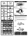
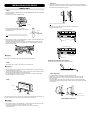
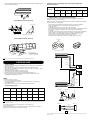
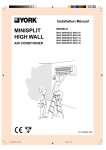
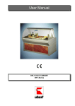
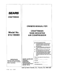
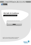
EN/FR
ENGLISH
∞ Do not conduct installation in wet area
or in the rain.
∞ This system is designed for domestic
or residential use only.
It is a high risk to cause the electrical shocks.
If used in certain envionments, such as
a manufacturing workplace, the equipment
may not function efficiently.
035T83007-000
INSTALLATION &
OWNER’S MANUAL
MINISPLIT HIGH WALL
AIR CONDITIONER
MODELS : MHC-MHH/BOC-BOH 07-35
n WARNING
Failure to follow a warning may result in death or serious injury.
n
CAUTION
Failure to follow a caution may result in serious injury or property damage, and in
certain conditions, may result in a grave consequence
• Electrical connections
All electrical wiring and connections must comply with local codes and standards.
Power supply cord and interconnection cord used must not be lighter than
Polychloroprene sheated cord (245 IEC 57 or H05RN-F).
Disconnecting device must have a contact separation of at least 3 mm.
• The following symbols are often used in this manual.
REQUIRED TOOLS
Strictly prohibited.
1.
2.
3.
4.
5.
6.
7.
8.
9.
10.
11.
12.
13.
14.
15.
Screw driver
Hexagonal wrench
Torque wrench
Spanner
Reamer
Hole core drill
Tape measure
Thermometer
Manifold Guage
Gas leak detector
Vaccum pump
Pipe clamp
Pipe Cutter
Flare Tool Set
Electrical Circuit tester
Be sure to follow the instructions.
Be sure to earth the air conditioner.
Be sure to disconnect the power plug.
Do not touch the air conditioner
with a wet hand.
Do not cause the air conditioner
(including the remote controller) to get wet.
_n
_ WARNING
Do not expose your body directly to the
cool (or hot) air for prolonged period; do
not cool (or hot) the room too much.
If anything abnormal such as a burning
smell occurs, stop the operation
immediately and turn the breaker off.
EXTENDED PARTS
1 Refrigerant Pipe
This could effect your physical condition and
cause health problems.
MHC-MHH/BOC-BOH
Models
07-09
12
18-35
Liquid size
1/4 inch
1/4 inch
3/8 inch
Gas size
3/8 inch
1/2 inch
5/8 inch
Do not put a finger, a rod or other
objects into the air outlet or inlet.
Do not attempt to extend the power cord
by joining it to another cord, or by using
an extension cord. Do not put any other
loads on the power supply socket.
2 Pipe Insulation Material (Polyethylene foam 9 mm thick)
3 Vinyl tape
4 Putty
SAFETY PRECAUTIONS
•
•
Please read this installation manual carefully before starting installation of the unit.
This air conditioning system contains refrigerant under pressure, rotating parts and
electrical connection which may be dangerous and can cause injury. Installation
and maintenance of this air conditioning system should only be carried out by
trained and qualified personnel.
• After unpacking, please check the unit carefully for possible damage.
• Before undertaking any work on the unit, make sure that the power supply has
been disconnected.
Continued abnormal operation will cause
troubles, electric shocks, fire etc. If anything
is abnormal consult the shop where you
bought the air conditioner.
As a fan is rotating at a high speed, it will
cause injury.
Do not attempt to repair, relocate,
modify or reinstall the air conditioner
by yourself.
Do not damage or attempt to modify the
power cord. Do not use the cord in a
damaged state or tie in a bundle.
CAUTIONS FOR INSTALLATION
∞ Do not store or unpack the unit
in a wet area or expose to rain
or water.
∞ Do not install in a place where
flammable gas may leak.
Incorrect work will cause electric shocks,
fire etc. For repairs and reinstallation,
consult the shop where you bought the air
conditioner.
n CAUTION
It may cause the unit to short circuit
and may result electric shocks or fire.
Before cleaning, be sure to stop the
operation and turn the breaker off.
Do not operate the air conditioner
with a wet hand.
As the fan is rotating at a high speed,
cleaning during operation may cause injury.
It may cause an electric shock.
It may cause fire.
Do not use the air conditioner for food
preservation purpose.
Ventilate the room from time to time.
NAME OF PARTS
INDOOR UNIT
AAA
BB
B
POWER
ON
OFF
G
EMERGENCY
OPERATION
F
Be careful especially when using a burning
appliance in the same room. Insufficient
ventilation may cause shortage of oxygen.
C
CC
E
D
Do not connect the air conditioner
to a power supply different form the
specification.
Do not stand or sit on the outdoor unit,
do not place any object on the unit.
H
A
B
C
D
Front Grille
Air Purifying Filter
Indicator Lamps
Flap Vertical Blades
E
F
G
H
It may cause trouble or fire.
Air Outlet
Air Filter
Air Inlet
Louver Horizontal Blades
OUTDOOR UNIT
After a long use, check the unit fixing
for damage.
Do not place a burning appliance in a place
exposed to the air flow form the unit or
under the indoor unit.
B
F
A
E
D
C
Do not wash the unit with water.
Do not place anything under the indoor
or outdoor unit which must be kept
away from moisture.
Air Outlet
Air Inlet
Refrigerant gas piping
A
B
C
Do not place a vessel containing water
on the unit.
D Refrigerant liquid piping
E Additional drain hose
F Connecting Cable
PREPARATION BEFORE INSTALLATION
Do not expose plants or animals directly
to the air flow.
Do not block air inlets or outlets.
• Before doing any work, check the interior power supply cord and the main breaker
capacity are sufficient and the installation area is sufficient and comp•lies with the
requirements.
• Check that the power supply available agrees with nameplate voltage.
• Electrical work, wiring and cables must be performed in compliance with national
and local wiring codes and standard.
• Do not use the extension cables. In the case extended cables are needed, use the
terminal block.
SELECTION OF THE LOCATION
• Select a place which provides the space around the units as shown in the
diagram below.
PART LIST
INDOOR
Name of part
Part No.
MHC-MHH/BOC-BOH
MHC-MHH/BOC-BOH
MHC-MHH/BOC-BOH
07, 09, 12
18, 25
35
Mounting Plate and Mounting Template
1
Quantity
X1
Indoor Unit
2
X1
Drain Hose
3
OUTDOOR
X1
*Included with
indoor unit
Central mounting bracket
4
X1
*Not supplied
Screws and Anchor Set
5
X4
Remote Control and Batteries set
˚C
˚C
+
+
E
TE
—
MOD
—
AR
—
SET
CLE
TE
E
+
—
MOD
SET
CLE
AR
—
˚C
R
—
MP
—
+
MP
—
MP
+
E
TE
—
MOD
—
AR
—
CLE
R
SET
TIME
X1
˚C
—
+
˚C
˚C
R
˚C
˚C
TIME
6
TIME
˚C
MHC-MHH/BOC-BOH
Models
07
Installation & Owner’s manual and user’ s guide
7
Installatio
Owner's manun &
al
User' s Guid
e
Installatio
Owner's manun &
al
User' s Guid
e
Installatio
Owner's manun &
al
A
User' s Guid
e
09
12
18
25
MHC-MHH/BOC-BOH
Models
35
60cm 60cm 60cm 60cm 60cm 60cm
07
A
09
12
18
25
35
20cm 20cm 20cm 20cm 20cm 20cm
B
70cm 70cm 70cm 70cm 70cm 70cm
B
60cm 60cm 60cm 60cm 60cm 60cm
C
60cm 60cm 60cm 60cm 60cm 60cm
C
40cm 40cm 40cm 40cm 40cm 40cm
D
10cm 10cm 10cm 10cm 10cm 10cm
D
20cm 20cm 20cm 20cm 20cm 20cm
X1
n CAUTIONS
ELECTRICAL WORK
∞ For power supply, be sure to use a separate power circuit dedicated to the air
conditioner. System relocation
• Do not install in a place that cannot bear the weight of the unit.
133.5
SYSTEM RELOCATION
133.5
∞ Relocating the air conditioner requires specialized knowledge and skills. Please
consult the shop where you bought the air conditioner if relocation is necessary
for moving or remodelling.
230
268
248
497
INSTALLATION IN THE FOLLOWING
PLACES MAY RESULT IN TROUBLE
BO 07-12
517
260
316
296
144
144
BO 18
429
100
550
Installation in the unit wrong direction.
Installation of outdoor units too close or,
blowing discharged air into each other.
Installation of the indoor unit in a place
where there is an obstacle near the air
inlet or outlet.
Installation of the outdoor unit in a place
exposed regularly to a strong wind.
Installation of the indoor unit at too low a
position
24
100
150
Installation of the indoor unit in
direct sun light.
335
287
315
234
64
24
64
150
BO 25-35
INSTALLATION
n CAUTION
n WARNING
The air conditioner must be
earthed in accordance
with the local codes.
Do not install the air
conditioner in places where
flammable gas may leak.
Incomplete earthing may result in
electric shock. Do not connect the
earth line to a gas pipe, lightening
rod or a telephone earth line.
If leaked gas should accumulate
near the unit, fire may occur.
Arrange the drain hose to
ensure smooth drainage.
Depending on the environment
and local codes, an earth
leakage breaker must be
installed.
OFF
Incomplete drainage may cause
wetting of the building, furniture
etc.
ON
Consult the service
shop or qualified
technician. Incorrect
installation will result in
water leakage, electric
shock or fire. For
installation, consult the
service shop where you
bought the unit or a
qualified technician.
10 cm
Do not attempt to
install the air
conditioney yourself.
INSTALLATION DIAGRAM
INSTALLATION SITE
10 cm or more
To install the air conditioner in the following types of environments,
consult the shop.
∞ Places with an oily ambient or where steam or soot occurs.
∞ Salty or corrosive environments such as coastal areas.
∞ Places where sulfide gas occurs such as hot springs.
The drain from the outdoor unit must be discharged to a place of good drainage.
Installation plate
60 cm or more
Remove the cover plate screw
to have access to the terminal
board.
60 cm or more
70 cm or more
CONSIDER NUISANCE TO YOUR
NEIGHBOURS FROM NOISES
Auto louver (vertical)
Manual louver (horizontal)
For installation choose a place as described below.
∞ A place solid enough to bear the
weight of the unit and which does not amplify
the operation noise or vibration.
∞ A place from where the air discharged
from the outdoor unit or the operation
noise will not annoy your neighbours.
Vinyl tape
Apply after carrying out
a drainage test.
* To carry out the drainage test.
remove the air filters and pour
water into the heat exchanger.
20
Inverter-type
fluoreascent lamp.
A place with good
ventilation.
TV
Air
Outlet
Air
Inlet
Conecting cable
Addinonal drain hose
cm
or
mo
re
20 cm or more
Liquid side piping
Gas side piping
To prevent
interierence,
place at least
1 m away.
Vinyl tape
Radio
60 cm or more
INSTALLATION PROCEDURE
Drain hose
• Drain hose is flexible and can be routed to suit various piping arrangements.
The drain line must include elbow trap (U bend). Connect a plastic condensate
pipe with an internal diameter of 12 mm.
INDOOR UNIT
Fixing
• Place the installation guide pattern on the designated installation place and mark
the hole position.
• Drill a hole and mount installation plate
Note: Do not put the drain hose end into water.
Ø 70 mm
.. .
... ...
... ..... ..
.. .
... ...... ..
. ...
.
.
.. .... ..
.. .
... ...... ..
. .
• After determining the pipe hole position.
Drill the hole at a slight downward slant towards
the outdoor side.
Indoor
Note : When installing the refrigerant pipes from others side.
A hole must be place to allow fall towards the outdoor unit.
.. .
... ...
... ..... ..
.. .
... ...... ..
.. .
... ...... .
.. ..
... ..... ..
.
... ....
• The drain hose can be connected to the left or the right side.
For left and left rear piping
For right and right rear piping
Outdoor
5
• Make ø5mm. 4-6 holes, in the wall at the four corners of mouting plate (bracket)
then insert appropriate mouting devices.
• Install the mounting plate using 4-6 pieces of mounting screw securely at four
corners and tighten the screw completely. Do not over tighten the screws and
deform the back plate.
Drain hose
Drain cap
For left and left rear piping
n Caution
Drain cap
Drain hose
Be careful when handling the sharp edge of the mounting plate.
Verification of condensate water drainage:
Fill the drain pan with water and observe evacuation.
Wiring
• This indoor unit is ready for connection to the outdoor unit.
n Cautions
• Never modify the unit by removing any of the safety guards or by bypassing any
of the safety interlock swithces.
• Connect the interconnecting cable correctly and connect the connecting cable to
terminal as identified with their respective marking.
• Do not damage the conductor core or inner insulation of power supply cables
and do not deform or crush the cables.
Indoor Unit Fixing
• Thread the indoor unit piping and cable through the hole.
• Hang the top of the unit onto the upper ridge of them in mounting plate.
• Make sure that the unit is correctly hung in place by sliding it to the left,
then to the right.
• Press the bottom left and bottom right hand corners of the unit against the
mounting plate until the fixing prongs click into place in the retainers provided
to that effect.
Piping
A Right
B Right
C Right
D Right
F Ieft
Drainage line
E Rear buttom
Interconnection cable
The auxiliary piping can be connected in the diections shown the above diagram. To
connect in the D, E and F direction, pipes will need to be extended.
(MHC-MHH/BOC-BOH 07-25)
n Cautions
• Bend pipes carefully to avoid flattening or obstructing them if the pipes are bent
incorrectly, the indoor unit may be unstable on the wall.
• Carefully arrange pipes so that pipes do not stick out of the rear plate
of the indoor unit
• For the model MHC-MHH 18, 25 and 35 and install the central mounting bracket as
shown in the below diagram.
Refrigerant charge to be added per extra metre of piping length when
more than 7.5 meters.
MHC-MHH/BOC-BOH
Unit size
g/m
7
9
12
18
25
35
15
15
15
40
40
40
Refrigerant piping connections (FLARE connections)
To avoid alteration of unit capacities, check that piping lengths and changes in
elevation are kept to a strict minimum.
(MHC-MHH /BOC-BOH 18, 25 and 35)
Before connection the refrigerant lines, follow the procedures below (if pre-charged
connection lines are not supplied):
Mounting Plate
-
Central Mounting Bracket
-
Select copper pipe diameters according to the size of unit to be installed.
Install the refrigeration lines, checking that no foreign boodies get
inside the piping.
Install the flare connectors and flare the ends of the pipes.
Evacuate the piping. This operation, which should last at least 15 minutes if there
are large piping lengths and changes in elevation, should be followed by
a leak test.
To this effect, when the piping has been evacuated, close the pressure gauge tap,
note the value on the gauge, then wait for 15 minutes. If the needle moves,
there is a leak in the system. Make the necessary adjustments or repairs
and repeat this procedure until the needle no longer moves.
Open the service valves and top up the refrigerant charge if necessary.
(MHC-MHH/BOC-BOH 18, 25 and 35)
Installation
Minimum thickness 6 mm
a
a)
Condensate
drainage line
Access plate for the
condensate drainage pump
detection (condensate pump
is available as an accessory).
Heat pump
(discharge)
Vinyl tape
Note: The condensate evacuation line should be taped to the refrigerant lines with vinyl tape.
Heat pump
OUTDOOR UNIT
D
Fixing and Piping
L
Liquid
Cooling
Cooling
(suction)
• Piping must be performed by qualified personnel according to good refrigeration
systems practices.
• Piping materials and insulation materials must be of refrigerant quality.
• Select the pipe diameters according to the size of unit and cut the pipe to design
length by using pipe cutter.
• Install the flare nuts and flare the end of the pipes.
• Check that no foreign bodies are inside the piping.
• Align the central of the connecting pipes and tighten the flare nut.
• Fix piping with pipe clamps and check that any pipe vibrations cannot be
transmitted to the building structure.
Head pump
(discharge)
Heat pump
Notes
L
Liquid
• Connect the pipe correctly.
• Do not apply the excessive torque.
• Use an appropriate bending tool to form curves and avoid over-tightening
the refrigerant tubes.
• To prevent heat loss, the two lines must be insulated separately.
H
GASS
Cooling
(suction)
Cooling
Maximum piping lengths
Unit size
7
9
12
18
25
35
Low pressure
D (m)
10
12
15
15
22
22
L (m)
12
15
18
18
25
25
H (m)
7
10
12
12
20
20
High pressure
Manifold
Gas value
Liquid value
Pressure tab
Note : Where the difference in elevation between the indoor unit and the outdoor unit is greater than 5 meters, install an
oil trap every 5 meters.
Outdoor unit
The suction line must have a 2% gradient up to the compressor
on horizontal sections.
Where piping lengths are unusually long and include a large number of oil traps, it
may be necessary to adjust to compressor charge.
Gas line
Indoor unit
Liquid line
R22
T his unit is shipped complete with a charge of R22 refrigerant that will be sufficient for an interconnecting piping
length of 5 meters.
Wiring sizes
Vertical Discharge Condensing Unit (H*DA, H*DB, H*RA)
The indoor unit and interconnecting wiring voltage is 220 volts. Where the outdoor unit
requires a different operating voltage such as 24 volts one of the following solutions
can be applied.
1. The coil of the relay switching the compressor and reversing valves should be
changed to a 220V coil.
2. A transformer should be installed to supply 24 volts and a relay installed with a 220
volt coil to switch the 24 volts required by the outdoor units. The transformer should
be energised at all times and not switched by the start signal from the indoor unit.
Switching the transformer directly will cause electronic noise which may cause
malfunction of the electronics.
Unit size
Power supply
7
2
9
12
18
3x2.5
mm
2
Interconnection
(Indoor/Outdoor)
Cooling mm
Heating mm2
Fuse
(Slow-Blow)
A
25
3x4
35
5x2.5
3x2.5 + Ground
4x2.5 + Ground
10
16
20
10
Or as required to meet national and local codes.
Notes
Power Supply
24 V FROM OUTDOOR UNIT
Cooling Only Units
Indoor Unit
• Terminals N and 1 (see diagrams above) correspond to power supply to the indoor
unit coming from the outdoor unit.
• Compressor power supply is established by teminal 2.
• Power supply to the 4-way valve is established by terminal 3.
• Outdoor fan power supply is connected to terminal 4.
• For further details on wiring of these units, see the diagrams pasted
inside each unit.
TEST OPERATION
Check this item before start operation
Wiring
Outdoor
• Check the flare nut connections, valve stem cap connections and service cap
connections for gas leak with a leak detector or soap water.
Indoor
•
•
•
•
•
Check the unit is firmly fixed.
Check the connecting pipes are tighten securely.
Check the pipe insulation.
Check the drainage.
Check the connection of the grounding wire.
PROTECTION MODES
Your air conditioner includes several automatic protection modes, which enables you
to use it virtually at any time and in any season, regardless of the outdoor temperature.
Some of the protection modes are listed below:
L N 1
Mode
2
Cooling
and Dry
Operation
conditions
Protection from
Controlled remedy
Low outdoor
temperature
Indoor coil
freezing up
Stop outdoor fan
and compfessor
when approaching
freezing conditions.
Resumes operation
automatic.
High outdoor
temperature
Outdoor coil
overheating
Stops compressor
when approaching over
heating conditions.
Resumes operation
automatic. operating
indicator blinks.
Low outdoor
temperature
Outdoor coil
ice build up
Reverses operation
from heating to cooling
for short periods to deice outdoor coil.
operating indicator blinks.
High indoor
or outdoor
temperature
Intdoor coil
overheating
Stop outdoor fan and
compressor when
approaching high
indoor coil
temperature.
Resumes operation
automatically.
For further detail on wiring of these units, see the diagrams pasted inside each unit
n Cautions
• Never modify the unit by removing any of the safety guards or by bypassing any of
the safety interlock swithces.
• Connect the connecting cable correctly and connect the connecting cable to
terminal as identified with their respective marks.
• Do not scratch the conductive core & inner insulator of power supply cables and do
not deform or smash on the surface of cables.
Electrical Connections
All electrical wiring and connections must comply with local codes and standards.
Power supply cord and interconnection cord used must not be lighter than
Polychloroprene sheated cord (245 IEC 57 or H05RN-F).
Disconnecting device must have a contact separation of at least 3 mm.
MHC-07-35 -Cooling Only
L
N
1
2
3
4
N
1
2
3
4
Indoor Unit
Outdoor Unit
Power 220-240V/1Ph/50Hz
Supply 208-230V/1Ph/60Hz
MHH-07-35 -Heat Pump
L
N
1
2
3
4
N
1
2
3
4
Indoor Unit
Outdoor Unit
Power 220-240V/1Ph/50Hz
Supply 208-230V/1Ph/60Hz
For correct installation, a proper ground connection must be made for unit.
Heating
TROUBLE SHOOTING GUIDE
Probable cause
Problem
Remedy
1.
2.
3.
4.
5.
6.
Power Failure.
Fuse blown or circuit breaker open.
Voltage is too low.
Faulty contactor or relay.
Electrical connections loose.
Thermostat adjustment too low (in heating mode)
or too high (in cooling mode)
7. Faulty Capacitor
8. Incorrect wiring, terminal loose
9. Pressure switch tripped
1.
2.
3.
4.
5.
6.
B. The outdoor fan runs but the compressor will not start.
1. Motor winding cut or grounded.
2. Faulty Capacitor.
1. Check the wiring and the compressor winding resistance.
2. Find the cause then replace Capacitor.
C. There is insufficient heating or cooling.
1. There is a gas leak.
2. Liquid and gas line insulated together.
3. The room was probably very hot (cool)
when you started the system.
1. Remove charge, repair, evacuate and recharge.
2. Insulate them separately.
3. Wait while unit has enough time to cool the room.
D. The compressor run continuously.
1. Thermostat adjustment too low (in heating mode) or too
high (in cooling mode)
2. Faulty fan.
3. Refrigerant charge too low, leak.
4. Air or incondensables in refrigerant circuit.
1. Check thermostat setting.
E. The compressor starts but shuts down quickly.
1.
2.
3.
4.
1.
2.
3.
4.
F. Clicking sound is heard from the air conditioner.
In heating or cooling operation any plastic parts may expand
or shrink due to a sudden temperature change in this event,
a clicking sound may occur.
A. The air conditioner does not run.
Too much or too little refrigerant.
Faulty compressor.
Air or incondensables in refrigerant circuit.
Changeover valve damaged or blocked open (heat pump unit)
Wait for Power resume.
Replace the fuse or reset the breaker.
Find the cause and fix it.
Replace the faulty component.
Retighten the connection.
Check Thermostat setting.
7. Find the cause then replace capacitor.
8. Check and retighten.
9. Find the cause before reset.
2. Check condenser air circulation.
3. Find leak, repair and recharge.
4. Remove charge, evacuate and recharge.
Remove charge, evacuate and recharge.
Determine the cause and replace compressor.
Remove charge, evacuate and recharge.
Replace it.
In heating or cooling operation any plastic parts may expand
or shrink due to a sudden temperature change in this event,
a clicking sound may occur.
BEFORE CALLING FOR SERVICE
Before calling for service, please check the following common maltufunctions and correct as needed.
Problem
Cause
Remedy
A. United does not operate. Stand-by indicator does not light up. 1. Unit not connected to power
2. Power failure.
1. Plug in the power cord.
2. Check main fuse.
B. Unit does not operat. Stand-by indicator lights.
1. Check remote control batteries.
2. Try to operate from a closer distance.
3. Start form on-units controls.
4. Perform reset operation by pressing button: TIMER UP buttons,
TIMER DOWN buttons, TIMER SET buttons, TIMER CEAR
buttons for 5 sec.
1. Unlock the remote control.
1. Remote control malfunctions.
1. The remote control is locked.
C. Unit does not respond property to remote control command.
1. Infra Red signal does not reach unit.
2. Distance between remote control and unit too large
or aimed at form improper angle
3. Infra Red reciever on-unit exposed to strong light source.
1. Check for obstruction between unit remote control.
Clear if need.
2. Get closer to unit.
3. Dim lights, fluorescents especiatlly.
D. Air does not blow out from indoor unit.
1. De-icing protection mode is activated.
2. Unit in AUTO FAN mode.
3. Over cooling in DRY.
1. Nomal operating in HEATING mode.
2. Nomal operating in DRY mode.
E. COOLING, DRY of HEATING does not start immediately.
1. 3-min. compresssor delayed start.
1. Nomal operating for these modes.
F. Unit functions but does not perform sufficiently.
1. Impropper temperature seating
2. Unit capacity insufficient for load or room size
1. Reset temperature.
2. Consult your dealer.
G. Filter indicator light up.
1. Air filter needs cleaning.
1. Clean filter, reinstall and reset indicator.
TECHNICAL SPECIFICATION
Models
Indoor
Unit
Power Supply
Maximum Power Consumtion
Running Current
Fuse size
System Operation Control
Compressoe Type
Power Supply
09
12
Outdoor
Unit
V/Ph/Hz
Ph
kW
07
09
12
1
0.7
1
0.85
1
1.2
A
A
3.5
10
4.5
10
5.6
10
Piping
Dimensions
Indoor
Outdoor
Indoor
Outdoor
18
25
35
18
25
220-240/1/50 or 315-450/3/50
1
1
2
2.8
35
BOC-BOH
Rotary
Maximum Power Consumtion
Running Current
Fuse size
Compreso Types
Weights
MHC-MHH
07
V/Ph/Hz
Ph
1
1
1
kW
A
A
0.8
3.5
10
1.09
4.5
10
1.2
5.6
10
9.1
11.5
16
20
Wireless Remote Control with LCD Display
Rot./Recip.
208-230/1/60 or 308-460/3/60
1
1
2.0
9.1
16
2.80
11.5
20
Rotary
Suction
Líquid
H(mm)
W(mm)
D(mm)
H(mm)
W(mm)
D(mm)
kg
kg
3/8"
1/4"
290
799
181
492
764
230
8
34
3/8"
1/4"
290
799
181
492
764
230
8
36
3
2.71
1
3.37
3
3.29
5.34
10
16.26
32
6.65
16
Reciprocating
1
3
3.71
17.04
4.05
6.94
10
Reciprocating
1/2"
1/4"
290
799
181
492
764
230
8
38
5/8"
3/8"
315
1019
180
590
820
280
12
59
5/8"
3/8"
356
1019
180
696
850
287
12
65
5/8"
3/8"
356
1156
203
900
850
285
23
76
MAINTENANCE
The units are designed to operate for long periods of time with a minimum of
maintenance. However, the following operation must be performed regularly.
Air filter
Maintenance operations
Clean
Recommended Frequency
Every month or more often
if necessary.
Air Purifying filter
Unit casing
Change/Replace a new set
Clean
Every 4 months
Every month or more often
if necessary
Drain pan and evacuation
Clean and check for
Each season before start up*
piping
Indoor/outdoor coils
Compressor
obstructions
Clean
No need
Each season before start up*
REPLACEMENT OF AIR PURIFYING FILTER
1 Remove the filter.
POWER
ON
OFF
EMERGENCY
*
OPERATION
2 Remove the air purifying filter.
This operation must be carried out by qualified personnel only.
Pull down
BEFORE MAINTENANCE
n
POWER
ON
OFF
Turn off the main breaker or disconnect
the main power supply.
push
EMERGENCY
OPERATION
3 Install a new air purifying filter.
Notes
• Don ’t spill water : There is a danger of electric shock.
• Don ’t used petrol, paint thinner, benzene or polishing agents : They may
deform or scratch the unit.
Pull up
POWER
CLEANING THE UNIT
ON
OFF
push
EMERGENCY
OPERATION
Wipe the unit with a soft dry cloth only. If the unit is very dirty,
wipe it with a cloth soaked in warm water
(Not more than 40 º C).
4 Reinstall the air filter and securely close the front panel.
Not more than
40˚C
POWER
ON
OFF
EMERGENCY
OPERATION
CLEANING THE AIR FILTER
1 Remove the air filter.
Lightly hold the knobs at both sides and lift a little to remove the filter to this side.
Air purifying filter
POWER
ON
OFF
• If the air purifying filter is clogged, it may lower the unit’s capacity or cause
condensation at air outlet.
• The air purifying filter is disposable. the standard usable interval is about 4 mounts.
However, if the color of the filter turns dark brown, replace it at once.
EMERGENCY
OPERATION
DE - COMMISSIONING DISMANTLING & DISPOSAL
2 Cleaning.
If the filter is very dirty, clean it with water (approx. 30˚C), and dry it thoroughly.
This product contains refrigerant under pressure, rotating parts,
and electrical connections which may be a danger and cause injury!
All work must only be carried out by competent persons using suitable
protective clothing and safety precautions.
Read the Manual
3 Reinstall the air filter.
POWER
ON
OFF
Risk of
electric shock
Unit is remotely controlled
and may start without warning
1. Isolate all sources of electrical supply to the unit including any control system supplies switched by the
unit. Ensure that all points of electrical and gas isolation are secured in the OFF position. The supply
cables and gas pipework may then be disconnected and removed. For points of connection refer to unit
installation instructions.
2. Remove all refrigerant from each system of the unit into a suitable container using a refrigerant reclaim
or recovery unit. This refrigerant may then be re-used, if appropriate, or returned to the manufacturer for
disposal. Under No circumstances should refrigerant be vented to atmosphere. Where appropriate,
drain the refrigerant oil from each system into a suitable container and dispose of according to local laws
and regulations governing disposal of oily wastes.
3. Packaged unit can generally be removed in one piece after disconnection as above. Any fixing down
bolts should be removed and then unit lifted from position using the points provided and equipment of
adequate lifting capacity. Reference MUST be made to the unit installation instructions for unit weight
and correct methods of lifting. Note that any residual or spilt refrigerant oil should be mopped up and
disposed of as described above.
4. After removal from position the unit parts may be disposed of according to local laws and regulations.
EMERGENCY
OPERATION
YORK® International Corporation