1
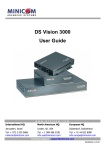
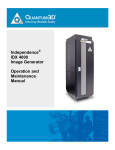
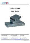
Phantom MX IP
Installation Guide
International HQ
North American HQ
European HQ
Italy
Jerusalem, Israel
Linden, New Jersey
Dübendorf, Switzerland
Rome
Tel: + 972 2 535 9666
[email protected]
Tel: + 1 908 4862100
[email protected]
Tel: + 41 1 823 8000
[email protected]
Tel: + 39 06 8209 7902
[email protected]
www.minicom.com
Customer support - [email protected]
5UM20109 V1.2 11/03
PHANTOM MX IP
Table of Contents
1.
2.
3.
4.
5.
6.
7.
8.
9.
10.
11.
12.
13.
14.
15.
16.
17.
18.
19.
20.
21.
22.
23.
24.
25.
26.
27.
28.
29.
30.
31.
32.
33.
Welcome .........................................................................................................................................2
Introduction ....................................................................................................................................3
The MX IP system components ....................................................................................................3
Management units .........................................................................................................................3
Remote units ..................................................................................................................................4
Compatibility ..................................................................................................................................5
System features .............................................................................................................................5
System configuration ....................................................................................................................6
Remote power management .........................................................................................................7
MX IP front panel............................................................................................................................8
The MX IP rear panel ports ...........................................................................................................9
Pre-installation instructions .......................................................................................................10
The MX IP system cables ............................................................................................................10
Connecting the MX IP ..................................................................................................................10
Connecting the UPM....................................................................................................................11
Connecting the MX IP system ....................................................................................................12
Connecting the MX IP to the UPM ..............................................................................................12
Connecting the Specters to the MX IP system .........................................................................12
Connecting the Specter II PS/2...................................................................................................13
Connecting the Specter RS232 ..................................................................................................13
The RS232 power options ...........................................................................................................14
Connecting the Specter SUN ......................................................................................................14
Connecting the Specter USB ......................................................................................................15
Connecting the RS232 terminal..................................................................................................15
Controlling the RS232 Specters .................................................................................................16
Connecting the RS232 terminal..................................................................................................16
Connecting the IPMI option ........................................................................................................17
Connecting the Internal Reset/Power Option ...........................................................................18
Connecting the External Reset/Power Option ..........................................................................19
Connecting to Ethernet ...............................................................................................................19
10 Mbps Connection....................................................................................................................19
100 Mbps Connection..................................................................................................................19
Connecting the RS232 Serial cable............................................................................................20
Appendix A:
Pin assignments ................................................................. 21
Appendix B:
Technical specifications .................................................... 23
1
INSTALLATION GUIDE
1. Welcome
The Phantom MX IP system is produced by Minicom Advanced Systems
Limited.
Technical precautions
This equipment generates radio frequency energy and if not installed in
accordance with the manufacturer’s instructions, may cause radio frequency
interference.
This equipment complies with Part 15, Subpart J of the FCC rules for a Class A
computing device. This equipment also complies with the Class A limits for radio
noise emission from digital apparatus set out in the Radio Interference Regulation
of the Canadian Department of Communications. These above rules are designed
to provide reasonable protection against such interference when operating the
equipment in a commercial environment. If operation of this equipment in a
residential area causes radio frequency interference, the user, and not Minicom
Advanced Systems Limited, will be responsible.
Changes or modifications made to this equipment not expressly approved by
Minicom Advanced Systems Limited could void the user’s authority to operate
the equipment.
Minicom Advanced Systems Limited assumes no responsibility for any errors that
appear in this document. Information in this document is subject to change
without notice.
No part of this document may be reproduced or transmitted in any form or by any
means, electronic or mechanical, for any purpose, without the express written
permission of Minicom Advanced Systems Limited.
© 2003 Minicom Advanced Systems Limited. All rights reserved.
Trademarks
PS/2 is a registered trademark of International Business Machines Corporation.
All other trademarks and registered trademarks are the property of their respective
owners.
2
PHANTOM MX IP
2. Introduction
The MX IP system from Minicom is a CAT5 based Distributed KVM Switching
system with remote KVM access via IP. You can remotely access up to 63
computers. The system can be managed and controlled by 1 or 2 users.
MX IP features remote KVM access and control via a LAN, Internet, or ISDN
connection. MX IP provides a non-intrusive solution for remote access and
control. Remote access and control software runs on the MX IP embedded
processors only and not on the servers, so there is no interference with server
operation or impact on network performance.
Use the MX IP in a multi administrator and multi server environment. The MX IP
combines digital remote KVM access via IP networks with a comprehensive and
integrated system management.
3. The MX IP system components
The MX IP system consists of:
•
The MX IP Management unit, plus the Optional Universal Phantom
Manager unit
•
Remote units
•
Cables and accessories
•
Marketing & Documentation CD
•
Optional IPMI Option. This is a serial cable for connecting the MX IP
and an IPMI V1.5 compliant serial management port on the remote
system.
•
Optional Internal Reset/Power Option. The internal reset/power option
(see Figure 2.2) consists of a PC bracket with a Sub-D 9 jack on the
outside and 4x2 pin connector in the inner side. The Sub-D 9 jack is
connected to the MX IP Serial Port 2. The internal 4x2 pin connector
allows to connect the reset and power on/off switching signals of the
main board to MX IP.
4. Management units
The 2 Management units are the MX IP and the Optional Universal Phantom
Manager (UPM). These are illustrated in the figures below.
3
INSTALLATION GUIDE
Figure 1 Phantom MX IP
Figure 2 Phantom UPM
5. Remote units
The Remote units are external boxes called Specters. Each remote computer has a
Specter connected to it. There are a number of Specter types as follows:
• For PS/2 interface computers – Specter II PS/2
• For SUN computers – Specter II SUN
• For RS232 controllable devices – Specter II RS232
• For computers with USB interfaces– Specter II USB
Figure 3 The Phantom Specter II PS/2
Figure 4 The Phantom Specter II SUN
4
PHANTOM MX IP
Figure 5 The Phantom Specter II RS232
Figure 6 The Phantom Specter II USB
6. Compatibility
The system is compatible with:
•
•
•
•
•
•
IBM compatible, Silicon Graphics, SUN and Alpha computers
VGA, SVGA, or XGA video standards
All major computer and server manufacturers
IntelliMouse™, Logitech WheelMouse, and PS/2 mice
Microsoft DOS, Windows 3.1, 95, 98, 2000, NT4, ME and XP. Novel, Linux, SGI,
BeOS, HP UX, Alpha UNIX, Open VMS
PS/2, SUN, RS232, USB interfaces
7. System features
•
•
•
•
•
•
•
•
Control and monitor mixed, multi-platform server environments of up to 63
remote computers from 2 Manager positions
Advanced On Screen Display management (including multi-layer security),
and BIOS level access
A total distance of up to 110m/360ft between the Manager computer and the
last connected Remote computer
KVM (keyboard, video, mouse) access over IP, ISDN or analogous telephone line.
Automatically senses video resolution for best possible screen capture
High-performance mouse tracking and synchronization
Connect a user console for direct access to KVM switch
Local Mouse suppression (only when using SUN's Java Virtual Machine)
MX IP supports PS/2 type keyboards and mice and HD 15 video output. See the
pin assignments in Appendix A.
5
INSTALLATION GUIDE
MX IP automatically detects the current video mode of the console, however
manual tuning is recommended to get the best video quality. MX IP will accept
video streams up to 110 MHz dot clock. This results in a screen resolution of
1280x1024 dots with a refresh rate of 75 Hz.
8. System configuration
Figure 7 illustrates the MX IP usage scenario
Figure 8 illustrates the basic configuration of MX IP, showing it connected to a
computer rack, the UPM, and to the IP network.
PHANTOM
Universal Manager
MINICOM
www.minicom.com
UPM
CAT5 cable
Administrator
Phantom Specters connected
to computers in a rack
SD
PHANTOM
Specter
1
PHANTOM
Specter
2
LINK
ACTIVE
MINICOM
LINK
ACTIVE
PHANTOM
MX IP
Activity
MINICOM
MINICOM
System OK
www.minicom.com
PHANTOM
Specter
3
PHANTOM
4
Specter
IP Network
LINK
ACTIVE
MINICOM
MX IP
LINK
ACTIVE
MINICOM
PHANTOM
Specter
5
Specter
6
Specter
Specter
Specter
LINK
ACTIVE
Optional host
computer - not part
of the system
MINICOM
PHANTOM
Specter
63
LINK
ACTIVE
MINICOM
PHANTOM
9
Administrator Client position
KVM signals
LINK
ACTIVE
MINICOM
PHANTOM
8
CAT5 cables
LINK
ACTIVE
MINICOM
PHANTOM
7
LINK
ACTIVE
MINICOM
PHANTOM
LINK
ACTIVE
MINICOM
Figure 7 MX IP usage scenario
6
PHANTOM MX IP
The MX IP system
A Dual-Management Server Solution over IP
2nd
Administrator
USER
POWER
1
To first Specter’s
System In port
SUN Specter
2
3 in 1 CPU
cable
LI NK
AC TIVE
MINICOM
PHANTOM
Specter
LIN K
A CTI VE
MINICOM
Total CAT5
cable length
in the
system - up
to 110m /
360ft
MX IP
UNIX Terminal Server
SERIAL 3
3
2nd
USER
OUT
SYSTEM
IN
SERIAL 2
SERVICE
SERIAL 1
USER
ETHERNET
LI NK
AC TIVE
MINICOM
Shielded CAT5
FTP cables
USB Specter
PHANSpecter
TOM
63
COMPUTER
RST
POWER
PHANTOM
Specter
P110
www.minicom.com
RS232 Specter
Windows 2000 Server
To System port
PS/2 Specter
PHANTOM
Specter
SUN Ultra 1U Server
SERVICE
UPM
85-265VAC 50/
60 Hz
ProLiant DL360 1U Server
COMPUTER
www.minicom.com
Connect up to 63 servers in the
system
85-265VAC 50/60 Hz
Mixed Platform Example - PS/2, SUN, RS232, USB
LI NK
AC TIVE
MINICOM
To last Specter’s
System Out port
IP Network
Remote
Administrator
Figure 8 MX IP basic configuration
9. Remote power management
There are three remote power management options:
•
Internal reset/power
•
External scalable power switch box
•
IPMI Version 1.5
The management system to use depends on the remote server interface.
Internal Reset/Power Option - This option applies to remote systems where no
IPMI Version 1.5 is available. The optional bracket is mounted in a free PCI/AGP
slot. Main board pins for reset and power on/off have to be connected to the
bracket. With this option it is possible to perform a remote reset, power cycle, and
power on/off.
External Power Switch Option - When there is neither a IPMI V1.5 option
available or the ability to place a bracket in the remote system, an external power
switch box can switch the power on and off.
7
SD
INSTALLATION GUIDE
IPMI Version 1.5 - defines a serial connection to access certain system
parameters and perform system actions like powering down or a hard reset.
Modern server systems, supporting the IPMI V1.5 specification, provide a mode
where the externally available COM2 serial connection can be configured as a
system management port (sometimes called an emergency management port). MX
IP may use this port in order to enable remote system management operations.
10.
MX IP front panel
Figure 9 illustrates the MX IP front panel.
PHANTOM
MX IP
MINICOM
Activity
System OK
www.minicom.com
Figure 9 Front panel
The table below explains the functions of the front panel LEDs.
LED
Function
Activity
LED blinks when Network connection is functioning
System OK
LED solid when IP Link system connected and functioning
8
PHANTOM MX IP
11.
The MX IP rear panel ports
The figure below illustrates the ports on the MX IP.
RS232
Terminal
port
Video In
SERIAL 3
COMPUTER
Serial 2
Serial 1
SERIAL 2
SERIAL 1
Video Out
USER
RST
2nd USER OUT
POWER
SYSTEM
IN
System
Out port
Keyboard
In port
Mouse
In port
Ethernet
Mouse
Out
Keyboard
Out
For optional
local computer
}
System
In port
Service
RS232
port
ETHERNET
}
2nd User port
SERVICE
For optional
KVM console
Figure 10 MX IP ports
You can work locally on the host system by connecting a KVM console to MX IP
rear panel.
Serial 1 port
Serial 1 port is used as follows:
•
IPMI Version 1.5 connection to the remote system using the IPMI Option
cable
•
Serial output for modem dial in connection
•
Serial pass-through via Telnet
•
Initial configuration
Serial 2 port
The Serial 2 port supports the internal and external power options
Ethernet
Connects the MX IP to an Ethernet network.
Reset (RST)
The Reset button resets the MX IP.
9
www.minicom.com
85-265VAC 50/60 Hz
Power connector
INSTALLATION GUIDE
12.
•
•
•
Pre-installation instructions
Switch off all computers, and disconnect the power cords
Place cables away from fluorescent lights, air conditioners, and machines that
are likely to generate electrical noise
Ensure that the total cable length does not exceed 110m / 360ft
13.
The MX IP system cables
The MX IP package contains the following cables.
3 in 1 CPU cable
Null Modem cable
CAT5 FTP cables
RS232 Serial cable
14.
Connecting the MX IP
Connect the MX IP as follows:
1. Connect the power cord and Ethernet and/or modem connection.
When connecting an optional local computer follow steps 2 and 3.
2. Connect the connectors of one end of the 3 in 1 CPU cable to the KVM
Computer ports of the MX IP.
3. Connect the connectors of other end of the 3 in 1 CPU cable to the KVM ports
of the host computer.
10
PHANTOM MX IP
4. You can connect a local KVM console to the User ports of the MX IP and
work locally on the Phantom system. Figure 11 illustrates the connections.
Optional local
computer
To computer's
Mouse port
USER
POWER
COMPUTER
www.minicom.com
85-265VAC 50/60 Hz
To computer's
Keyboard port
SERVICE
UPM
To System port
To
computer's
Video card
3 in 1 CPU
cable
P110
SD
SERIAL 3
COMPUTER
SERIAL 2
SERIAL 1
USER
RST
2nd USER OUT
POWER
SYSTEM
IN
SERVICE
ETHERNET
To 2nd
User port
To first Specter’s
System In port
To
System
Out port
www.minicom.com
85-265VAC 50/60 Hz
MX IP
Optional KVM
console
To
System
In port
Shielded CAT5
FTP cables
To last Specter’s
System Out port
Figure 11 MX IP connections
15.
Connecting the UPM
The optional UPM can be used by a 2nd administrator to control computers in the
system. You have the option to connect a computer to the UPM and work locally.
To connect the UPM see the hardcopy UPM Quick Installation Guide and the
softcopy UPM Installation Guide located on the Marketing & Documentation CD.
11
INSTALLATION GUIDE
16.
Connecting the MX IP system
The MX IP system is connected using Shielded CAT5 FTP System cable. The
Shielded CAT5 FTP System cable consists of a Shielded CAT5 FTP (Foil
Shielded Twisted Pair) Solid Wire 2x4x24 AWG (America Wire Gauge) cable
terminated with RJ-45M connectors.
The total length of the CAT5 cables in the system can be up to 110m/360ft, see
the configuration diagram on page 7. This includes the CAT5 loop and the cable
distance from the MX IP to the UPM.
Recommendation. Before installing the Shielded CAT5 FTP System cable, work
out how to connect all the computers using the shortest possible length of cable. A
shorter cable length increases video quality, and reduces noise.
Note: If the supplied Shielded CAT5 FTP System cable length is not appropriate
for your configuration, a custom length cable can be substituted. If you choose to
use a cable with a different length, make sure to use CAT5 FTP (Foil Shielded
Twisted Pair) Solid Wire 2x4x24 AWG cable, according to the T568B wire
diagram.
The Shielded CAT5 FTP cables connect the Phantom system in a loop.
Connect one Shielded CAT5 FTP System cable to the MX IP as follows:
1. Connect one connector to the System Out port.
2. Connect the other connector to the last Phantom Remote’s System In port.
Connect another Shielded CAT5 FTP System cable to the MX IP as follows:
1. Connect one connector to the System In port.
2. Connect the other connector to the first Phantom Remote’s System Out port.
17.
Connecting the MX IP to the UPM
Connect the MX IP to the UPM with a Shielded CAT5 FTP System cable as
follows:
1. Connect one connector to the MX IP’s 2nd User port.
2. Connect the other connector to the UPM’s System port.
18.
Connecting the Specters to the MX IP system
All the Phantom Specters connect to the system using Shielded CAT5 FTP
System cables.
Figure 12 illustrates the System In/Out ports on all Phantom Specter models.
12
PHANTOM MX IP
Phantom
Specter
IN
OUT
SYSTEM OUT
SYSTEM IN
Figure 12 The Phantom Specter ports
19.
Connecting the Specter II PS/2
Connect the Specter as illustrated in the figure below. Connect the Specter to a
computer with the built-in cables. Connect the Specter to the Phantom system
using Shielded CAT5 FTP cables. The Phantom Specter draws its power via the
computer’s Keyboard port.
To Computer’s
Keyboard Port
To System In port of next
To System Out port
unit
Shielded CAT5 FTP System cables
To System Out port of
previous unit
To Computer’s
Mouse Port
To System In port
To Computer’s
Video Card
Figure 13 The Specter II PS/2 connections
20.
Connecting the Specter RS232
To connect the Specter RS232:
1. Connect the Specter to a computer with the built-in cables – see the figure
below.
2.Connect the Specter to the Phantom system using Shielded CAT5 FTP cables.
13
INSTALLATION GUIDE
21.
The RS232 power options
1. USB connection for power only – see Figure 14.
To USB Port
(for power only)
To RS232 Port
To System IN port of next
To System Out port
unit
Shielded CAT5 FTP System cables
To System Out port of
previous unit
To System In port
Figure 14 The Specter RS232 connections
2.Server without USB - connect a USB to PS/2 Adapter – illustrated below.
Connect the adapter to the Keyboard port.
Figure 15 The USB to PS/2 Adapter
3.External power - connect USB connector to power adapter
22.
Connecting the Specter SUN
Connect the Specter as illustrated in the figure below. Connect the Specter to a
computer with the built-in cables. Connect the Specter to the Phantom system
using Shielded CAT5 FTP cables. The Phantom Specter draws its power via the
computer’s Keyboard port.
To Computer’s
Video Card
To System Out port
To System IN port of next
unit
Shielded CAT5 FTP System cables
To System Out port of
previous unit
To System In port
Figure 16 The Specter SUN connections
14
To Computer’s
Keyboard Port
PHANTOM MX IP
23.
Connecting the Specter USB
Connect the Specter as illustrated in the figure below. Connect the Specter to a
computer with the built-in cables. Connect the Specter to the Phantom system
using Shielded CAT5 FTP cables. The Phantom Specter draws its power via the
computer’s USB port.
To Video Card
To USB Port
To System IN port of next
To System Out port
unit
Shielded CAT5 FTP System cables
To System Out port of
previous unit
To System IN port
Figure 17 The Specter USB connections
24.
Connecting the RS232 terminal
When there are RS232 Specters in the system, you can control them through an
RS232 terminal.
•
When a computer is connected to the Phantom Manager, control the
RS232 servers via the computer’s Terminal emulation software OR
optional terminal.
•
When no computer is connected to the Phantom Manager, control the
RS232 servers via the terminal.
15
INSTALLATION GUIDE
25.
Controlling the RS232 Specters
You can control the RS232 Specters from the Telnet window of the Phantom MX
IP when the system is connected over the Ethernet.
Connect the Null Modem cable to the MX IP as illustrated in the figure below.
P110
SD
Null Modem
cable
SERIAL 3
COMPUTER
SERIAL 2
MX IP
SERIAL 1
USER
RST
POWER
26.
To Serial
1 port
2
nd
USER OUT
SYSTEM
IN
SERVICE
ETHERNET
Connecting the RS232 terminal
Connect the RS232 terminal to the MX IP as illustrated in the figure below.
See Appendix A for the RS232 Terminal Connector pin-out.
16
www.minicom.com
85-265VAC 50/60 Hz
To Serial
3 port
PHANTOM MX IP
RS232
Terminal
P110
SD
Login: admin
Password_|
d i g i t a l
VT420
Contrast
Bright
MX IP
SERIAL 3
COMPUTER
SERIAL 2
SERIAL 1
USER
RST
POWER
2nd USER OUT
SYSTEM
IN
SERVICE
ETHERNET
Figure 18 The RS232 terminal connected to the MX IP
27.
Connecting the IPMI option
IPMI Version 1.5 defines a serial connection to access certain system parameters
and to perform actions like switching off the system or performing a hard reset.
Connect a Serial cable to a Serial port on the host computer and the Serial 1 or 2
port on the MX IP.
For further information about IMPI 1.5, see
http://developer.intel.com/design/servers/ipmi/tools.htm
To use the IPMI over a serial interface enable it in the host computer. This is done
using BIOS settings or special utilities provided by the server manufacturer. Refer
to the server manufacturer's manual site.
17
www.minicom.com
85-265VAC 50/60 Hz
To Serial
port 3
INSTALLATION GUIDE
Note! IPMI V1.5 is only supported by server systems manufactured in 2002
onwards.
28.
Connecting the Internal Reset/Power Option
Figure 19 shows the top view of the reset/power bracket.
To Reset pin
on Mainboard
To front panel
Reset switch
To Power On pin
on Mainboard
To front panel
Power switch
Figure 19 Reset/power bracket
Additional cables are required to enable the remote reset and power functions.
To install the bracket:
1. Mount the bracket in a free slot of the controlled system.
2. Find and disconnect the cable connecting the front panel reset button to the
main board.
3. Connect the cable to the pin connector on the bracket as shown in Figure 19.
4. Take the red/black reset cable and connect one end to the Motherboards reset
jumper connector and the other end to the bracket connector.
5. Find and disconnect the cable connecting the front panel power button and the
Motherboard.
6. Connect it to the pin connector on the bracket.
7. Take the red/black power cable and connect one end to the Motherboard 's
power jumper connector and the other end to the bracket connector.
8. Connect the bracket to the MX IP Serial port 2 using the supplied SUB-D 9 to
SUB-D 9 connector.
18
PHANTOM MX IP
29.
Connecting the External Reset/Power Option
Refer to the of the External Power Switch Option guide to connect this to one of
the serial ports. To date supported options are:
•
SPC 800/1600
•
Sentry In-Line Power Module
•
Intelligent Power Module
•
Leunig ePowerSwitch
•
Leunig ePowerSwitch –M/S
30.
Connecting to Ethernet
The Ethernet connector on the MX IP can be used either for a 100 Mbps
100BASE-TX connection or for a 10 Mbps 10BASE-T connection. The adapter
adjusts to the appropriate operation mode automatically.
31.
10 Mbps Connection
For 10BASE-T Ethernet networks, the Fast Ethernet adapter uses Category 3, 4,
or 5 cable. To establish a 10 Mbps connection, the cable must be connected to a
10BASE-T hub. Ensure the cable is wired appropriately for a standard 10BASE-T
adapter. Align the RJ-45 plug with the notch on the adapter's connector and insert
it into the adapter's connector.
32.
100 Mbps Connection
For 100BASE-TX Fast Ethernet networks, the MX IP supports Category 5
cabling. To establish a 100 Mbps connection, the cable must be connected to a
100BASE-TX hub.
1. Make sure that the cable is wired appropriately for a standard 100BASE-TX
adapter.
2. Align the RJ-45 plug with the notch on the adapter's connector and insert it into
the adapter's connector.
Note! The UTP/FTP wire pairs and configuration for 100BASE-TX cable are
identical to those for 10BASE-T cable when used with Category 5 UTP/FTP
cable.
19
INSTALLATION GUIDE
33.
Connecting the RS232 Serial cable
To operate the Phantom system with the Control software located on the
Marketing & Documentation CD, connect the RS232 Serial cable.
To connect the RS232 Serial cable:
1.
Connect the cable’s RJ11 connector to the MX IP’s Service connector. See
Appendix A for the Service Connector Pin-out.
2.
Connect the cable’s DB9F connector to a Serial port on the computer’s rear
panel.
The figure below illustrates the connections.
P1 10
SD
Computer screens
appear here
SERIAL 3
COMPUTER
SERIAL 2
SERIAL 1
USER
RST
POWER
2nd
USER OUT
SYSTEM
IN
SERVICE
ETHERNET
To Service
connector
RS232 Serial
cable
Control software
installed here
To computer’s Serial port
Figure 20 The MX IP with the RS232 Serial cable
20
www.minicom.com
85-265VAC 50/60 Hz
MX IP
PHANTOM MX IP
Appendix A: Pin assignments
RJ 45 Connector Ethernet
8
Pin
1
2
3
4
1
Assignment
TX +
TX RX +
Not connected
Pin
5
6
7
8
Assignment
Not connected
RX Not connected
Not connected
Serial SUB-D 9 Connector 1
1
2
6
Pin
1
2
3
4
5
3
7
4
8
5
9
Assignment
DCD
RX
TX
DTR
GND
Pin
6
7
8
9
Assignment
DSR
RTS
CTS
RI
Serial SUB-D 9 Connector 2
1
2
6
Pin
1
2
3
4
5
3
7
4
8
Assignment
DCD
RX
TX
DTR, Reset1
GND
5
9
Pin
6
7
8
9
Pins 1 and 6 are bridged
21
Assignment
DSR, Reset2
RTS, Power1
DTS, Power2
Not connected
INSTALLATION GUIDE
RS232 Serial cable pin-out
RJ11 Service
1
2
3
4
5
6
Signal
N/C
TXD
RXD
N/C
GND
N/C
Serial SUB-D 9 Connector 3
Pin
1
2
3
4
5
6
7
8
9
Signal
N/C
RXD
TXD
DTR
GND
DSR
RTS
CTS
N/C
22
DB9
2
3
5
-
PHANTOM MX IP
Appendix B: Technical specifications
Host computer Operating systems
DOS, Novel, Linux, UNIX, Windows 3.1,9X, ME,
NT4, 2000, XP, 2003 Server and later
Client computer Operating systems
Windows 98, ME, 2000, XP and later, Linux,
MAC and SUN. Internet browser with full Java
support
Host computer –
resolution
Up to 1280x1024 @75Hz
Client computer –
resolution
Recommended resolution should be higher than
host computer resolution
Number of Remote
Units
63
Maximum KVM
System cable
distance
110m/360ft
MX IP to local KVM
connection
Screen – HDD15; Keyboard/Mouse – MiniDIN6
MX IP to computer
connection
3 in 1 CPU cable 1.8m:
HD15-MiniDIN6-MiniDIN6 (Supplied with
system)
Line connection
RJ45 – LAN, Autosensing 10/100 Mbit/s
RJ45 - 2nd user CAT5 FTP cable
2 x RJ45 - System
Serial connection
3 x DB9:
COM1 for initial configuration and external
modem. Power.
COM2 for power management only.
COM3 for RS-232 applications.
Service connection
RJ11
Product weight
2.2 kg / 4.8 lb
Shipping weight
2.7 kg / 6.0 lb
Dimensions
431mm x 176mm x 41mm / 17" x 6.9” x 1.6”
Power supply
85 – 265 VAC
50 / 60 Hz
23
INSTALLATION GUIDE
Operating
temperature
5°C to 40°C / 41° to 104°F
Storage temperature
-40°C to 70°C / -40° to 158°F
Operating humidity
10% to 90% (non-condensing)
Storage humidity
5% to 95% (non-condensing)
Warranty
3 years
24
PHANTOM MX IP
25