1
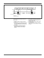
Tech Note
CAN bus components
Introduction
HN.50.Y1.02 is new
Introduction
Danfoss has introduced a new remote control
system with CAN bus components that will
give customers greater flexibility as far as their
particular application needs are concerned. In
the new series, focus has been particularly
concentrated on:
•
•
•
•
•
Improved performance
Lower installation costs
Easier servicing
Improved safety
Flexibility
CAN components can be used together with
PVG 32, PVG 120 and PVG 83.
What is CAN bus
The CAN (Controller Area Network) bus was
originally designed for the automobile industry.
It is a serial communication interface in which
special emphasis is placed on the following
parameters:
•
•
•
•
Safety
Reliability
Real time control
Costs (installation/service)
10-1998
HN.50.Y1.02
Book 9 Partition 5
1
CAN communication
CAN communication is best understood in the
following way:
Instead of sending a message from component A to unit B, it is broadcast. Each component, a PVG CIP for example, is then able to
listen in and col-lect information relevant to it
selv. The message format is designated COB
(Communication Object), which applies to all
messages.
A COB has an identification code (COB-ID)
that makes it possible for a component, a PVG
CIP for example, to sort and prioritise transmitted communication objects (COBs). The
COB-ID clearly identifies the COB in a network.
CAN communication works on the prioritising
of messages, thus CAN uses familiar and
established methods such as CSMA/CA
(Carrier Sense, Multiple Access with Collision
Avoidance) with improved capability to avoid
collision (non-destructive bit arbitration). This
means that the message with the lowest identification code will have access to the bus
before other messages, ensuring that the
capacity of the bus can be utilised to the maximum.
The speed of the bus is limited by its length,
see below.
Baud rate
Bus length
CANopen
CAN components communicate using a
protocol. A protocol can be compared to a
language. The different protocols on the
market are adapted to the applications in
which they are used.
The CANopen protocol is particularly suitable
for mobile applications. There are many
suppliers on the market whose products work
together with CANopen, therefore it is easy to
put together a comprehensive CANopen
system.
CANopen uses objects for communication.
The most common are:
Service Data Object(SDO)
SDOs transfer large amounts of information
that is not time-critical eg setting-up parameters.
Process Data Object (PDO)
PDOs are used to transfer data that are timecritical. For example, joysticks transfer signals
via PDOs.
2
HN.50.Y1.02
NMT is a special part that handles emergency
situations and other network administration.
Via an emergency object, the individual nodes
(components) are able to send a warning of
emergency situations. In this way, other CANopen components are able to identify the node
point from which the emergency call was sent.
CANopen specifies an Object Dictionary (OD)
that describes all parameters in the product.
This OD does not function solely as a specification file, but also as an interface with other
CANopen devices. In other words, a description is given detailing which parameters are
necessary to activate the different functions
the product can perform.
Prop 1
Start of frame
Identification code
Prop 2
Prop 3
Prop 4
Prop 1-4
Data field
DLC (Data
Length Code)
Push 1
Push 2
Push...
CRC
Receipt field
RTR (Remote
Transmission Request)
The example above shows the structure of a
joystick COB.
1. A COB is started by sending a 0 (start of
frame).
2. An identification code (COB-ID) is sent and
through bit arbitration the message having
the lowest bit identification code is allowed
to continue.
3. RTR (Remote Transmission Request)
specifies whether the sender wishes to
receive or send data to the message
receiver.
HN.50.Y1.02
4. DLC specifies the length of the data field.
5. The data field contains information on, for
example, joystick data.
6. The CRC field is used as a safety control
for finding bit error.
7. The receipt field is a position in which all
other components acknowledge receiving a
message.
3
Danfoss CAN concept
CAN components supplied by Danfoss can be
identified from the abbreviation CIP (CAN
Interfaced Product). We supply the following:
• PVG CIP
• Prof 1 CIP
• CIP Configuration Tool
Our objective is to supply CAN components
which are not only capable of communicating
with our own products, but also with other
Prof 1 CIP
The Prof 1 CIP joystick is available in many
mechanical configurations. To simplify the way
in which this information is shown in the COB,
the maximum configuration possibilities are
always built in. Depending on the actual configuration of the joystick, some of the fields for
proportional or on/off signals contain no information. The joystick sends information on the
first PDO (Process Data Object). As standard,
it sends cyclically at Tc = 10 ms.
The Emergency Object is used if a fault arises
in the joystick.
Prof 1 CIP can be ordered as described in
Tech Note HN.50.Z3 Joystick Prof 1. New
modules for Prof 1 CIP are shown in the table
below.
PVG CIP
The CIP Configuration Tool is designed to
guide hydraulic system designers/ service
technicians through system setup.
Prof 1 CIP contains new functions often requested in hydraulic systems:
Joystick guide (x - y interlook)
This function ensures that only the first proportional signal activated from the control lever is
sent (prop 1 or prop 2).
Memory function
This function makes it possible for the user to
hold a proportional function by pressing a
selected memory button (on/off) in the
joystick. The associated proportional signal
can be deactivated by pressing the memory
button again or by activating the proportional
function in the opposite direction.
Name
Code no. 162B....
Pos. no. in code no. list
Cable
6100
6
Length 230 mm with
AMP 282404-1, male plug
AMP 282107-1, tab house
Main function module with
electronics
5100
5
CAN electronics
PVG CIP is designed to control up to eight
sections equipped with PVEO, PVEM, PVEH
or PVES, and versions with float position control.
PVG CIP is able to receive COBs sent in
joystick format from four joysticks or other
sources. The joystick signals are distributed to
the PVEs in relation to the actual setup. The
CAN signals are converted to proportional or
on/off values on the output pins of the module.
PVG CIP contains functions often used in
hydraulic systems:
Name
PVG CIP
4
standard available components. There are
many suppliers of CANopen components on
the market and therefore it is simple, inexpensive and very flexible to set up a comprehensive system.
HN.50.Y1.02
Code no.
155U....
5660
Description
• Two different ramps (principle 1 from EH
boxes)
• Flow limitation
• Deadband compensation
• Gain
• Software tuning of spool characteristics
• Spool float position control
• Power saving
• Service and diagnosing
• Softwiring
PVG CIP must be ordered as a separate component with code number as follows.
Description
With AMP plug 1-967280-1, male plug
CIP Configuration Tool
The CIP Configuration Tool is a program
developed for setting up systems consisting of
PVG CIP and Prof 1 CIP.
Code no.
155U....
5670
Name
CIP Configuration Tool
Description
Product contents
• CIP Configuration Tool
• CIP Downloading Utility
• CANview
• CAN dongle
• Documentation, examples, help files
Technical data
Common to PVG CIP &
Prof 1 CIP
Power supply
Supply voltage
Max. supply voltage
Max. pulsation (peak to peak)
Udc
10 - 30 V DC
36 V DC
5%
CAN interface - ISO 11898 ver. 2.0 B
Baud rate
Communication profile
Typical start-up time
CAN
10 Kbit/s - 1000 Kbit/s
CANopen ver. 3.0
< 500 ms
Full CAN
EMC - EMC Directive (89/336/ECC)
Emission
Immunity
EN 50081-2
EN 50082-2
ISO 14892 (60 V/m, 20 MHz - 1000 MHz)
ISO 13766 (60 V/m, 20 MHz - 1000 MHz)
HF immunity
Environmental data
Storage temperature
Operating temperature
Ambient temperature
Termination
A CAN bus must be terminated at both ends
where CAN+ and CAN- are to be connected
via a 120 Ω resistor.
Prof 1 CIP
CAN_TERM
CAN+
Pin 1
Pin 4
-40°C to +90°C
-30°C to +70°C
Termination can be effected by connecting a
jumper between the pins given below (a 120 Ω
resistor is fitted in the component).
PVG CIP
CAN_TERM
CAN+
Pin 16
Pin 3
References
ISO 11898
CANopen
EMC Directive
ISO 14892
ISO 13766
HN.50.Y1.02
Vehicles, interchange of digital information - Controller Area
Network (CAN) for high-speed communication
CANopen communication profile for industrial systems, CiA
standard draft 3.0
Revision 3.0
89/336/ECC
Agricultural and forestry machines - electromagnetic compatibility
Earth-moving machinery - electromagnetic compatibility
5
Prof 1 CIP data format
The data format is independent of the mechanical configuration. It is manufactured so that
a signal for an 8-bit processor can be extracted without signal manipulation. This gives 8bit signal resolution, and in order to get full
resolution (10 bit) signal manipulation is
necessary. This is standard on PVG CIP.
The data format is “twos complement” and is
shown in the figure below.
1 byte SIGN----MSB --------------------------------------------------------Prop1------------------------------------------------------------------2 byte SIGN----MSB --------------------------------------------------------Prop2-------------------------------------------------------------------3 byte SIGN----MSB --------------------------------------------------------Prop3-------------------------------------------------------------------4 byte SIGN----MSB --------------------------------------------------------Prop4-------------------------------------------------------------------5 byte
6 byte
rest_Prop4 - LSB
rest_Prop2 - LSB
rest_Prop1 - LSB
Push 7
Push 6
Push 5
Push 4B
Push 4A
Push 3B
Push 3A
8 bit
7 bit
6 bit
5 bit
4 bit
3 bit
2 bit
1 bit
SIGN = +/−
MSB = Most significant bit
LSB = Least significant bit
6
rest_Prop3 - LSB
Push 8
HN.50.Y1.02
PVG CIP specification
Electrical
PVE outputs
8
PVE types that can be connected
PVEO, PVEM, PVEH, PVES incl.
versions with float position
PVPX/PVPE outputs
Resolution
1
9 bit (-100% to +100%)
AMP part no. 1-967280-1, PCB-connector
AMP part no. 1-967281-1, Timer house
AMP part 0-929937-1, junior contact
AMP part 0-962876-2, micro contact
AMP part no. 0-965643-1, cover
Seals and plugs
Slave only
Plug type
(Only part no. 1-967280-1 supplied with PVG)
CAN setting
Plug connections
Pin number
1
2
3
4
5
6
♣ When using PVEO
∇ When using PVEM/H/S
7
8
9
10
11
12
13
14
15
16
17
18
19
20
21
Name
PVPX out
CAN+
CAN+
Alarm_1
Alarm_2
Gnd
Alarm_3
Alarm_4
Alarm_5
Gnd
Alarm_6
Alarm_7
Alarm_8
Gnd
Udc
CAN_TERM
Gnd
PVE1_A ♣
PVE2_A ♣
PVE3_A ♣
Gnd
PVE1 signal ∇
PVE2 signal ∇
PVE3 signal ∇
Pin number
22
23
24
25
26
27
Name
PVE4_A ♣
PVE5_A ♣
PVE6_A ♣
Gnd
PVE7_A ♣
PVE8_A ♣
28
29
30
31
32
33
34
35
36
37
38
39
40
41
42
Gnd
Udc
CANCANPVE1_B ♣
PVE2_B ♣
PVE3_B ♣
Gnd
PVE4_B ♣
PVE5_B ♣
PVE6_B ♣
Gnd
PVE7_B ♣
PVE8_B ♣
Gnd
PVE4 signal ∇
PVE5 signal ∇
PVE6 signal ∇
PVE7 signal ∇
PVE8 signal ∇
PVE1 Udc ∇
PVE2 Udc ∇
PVE3 Udc ∇
PVE4 Udc ∇
PVE5 Udc ∇
PVE6 Udc ∇
PVE7 Udc ∇
PVE8 Udc ∇
PVEM/H/S
Voltage, neutral position
Voltage, full flow port A
Voltage, full flow port B
Version with float position control
50% of Udc
25% of Udc
35% of Udc
75% of Udc
Version with float position control
65% of Udc
Voltage, float position
control
Version with float position control
80% of Udc
Alarm input signals
Low
High
< 1,6 V
> 85% of Udc
3%
5%
10 Hz
± 1 mA
Max. linearity deviation
Max. pulsation content
Max. band width
Max. output current
(f > 2 kHz)
PVPE/PVPX
PVEO
Max. output current
1,2 A
Max. output current
3A
Note: To ensure maximum safety, the normally open (NO)
version of PVPE/PVPX is recommended.
Environmental data
IP classification
HN.50.Y1.02
IP 66, IEC 529
7
Prof 1 CIP specification
Electrical
Proportional signals max.
Resolution
Operating buttons on/off max.
DIP switch settings
DIP no. 1
DIP switch settings
DIP no. 2
Plug type
Only part no. 282404-1 and no. 282107-1 supplied
Plug connections
Pin number
1
2
3
4
5
Safety aspects
4
9 bit (-100% to +100%)
6
Open = CANopen min. master
Closed = CANopen slave
Open = Default baudrate and Node id
Closed = Baudrate and Node id acc. to OD
AMP part no. 282404-1, male plug
AMP part no. 282403-1, female plug
AMP 282107-1, tab house
AMP 282089-1, plug house
Seals and plugs
Environmental/mechanical
As analog version
Name
CAN_TERM
Udc
Frame
CAN+
CAN-
Both PVG CIP and Prof 1 CIP are designed to
give maximum safety. They both incorporate
self-test functions, signal protection and
‘watchdogs.
The self-test is performed when power is
applied and before any of the PVE outputs are
activated. The unit then goes to the operating
function and a series of running tests are
carried out. A list of these tests is given below.
Self-tests
PVG CIP
1.
2.
3.
4.
5.
Prof 1 CIP
Internal RAM test
External RAM test
EE-PROM test
FLASH test
Test of feedback monitoring (tests all outputs
for short-circuiting to earth and Udc)
1. Internal RAM test
2. EE-PROM test
3. FLASH test
Running tests
PVG CIP
Prof 1 CIP
1. Watchdog
2. PVEH alarms
3. Signal protection
1. Watchdog
2. Potentiometer control
To ensure optimum system function, two safety levels are used:
• Fail-safe condition
• Alarm condition
Fail-safe condition
PVG CIP
Prof 1 CIP
PVE forced to neutral position.
Neutral position signal sent from
the joystick to all PVEs.
Voltage supply to PVE cut off.
Alarm signal sent on bus so that
a third unit is able to take appropriate action.
8
HN.50.Y1.02
Alarm signal sent on bus so that
a third unit is able to take appropriate action.
Alarm condition
PVG CIP
Alarm signal sent on bus so that
a third unit is able to take appropriate action.
Depending on OD-index 2108
subindex 1, PVPX/PVPE dump
valve dumps pressure in alarm
condition. Because this is an NO
valve (normally open) voltage
must be cut off.
Fail-safe condition arises when faults of the
following types occur:
PVG CIP
Description
PVEs that go into fail-safe
condition
1000
5000
5001
5002
5003
5004
5005
5006
5007
5008
5009
500A
500B
500C
500D
5016
6300
Generic fault
System hardware
Self-test fault, internal RAM
Self-test fault, external RAM
Self-test fault, EE-PROM
Self-test fault, FLASH
Self-test fault, feedback test # 1
Self-test fault, feedback test # 2
Self-test fault, feedback test # 3
Self-test fault, feedback test # 4
Self-test fault, feedback test # 5
Self-test fault, feedback test # 6
Self-test fault, feedback test # 7
Self-test fault, feedback test # 8
Self-test fault, feedback test PVPX
Watchdog fault
Joystick data format nonconformance
All PVEs
All PVEs
All PVEs
All PVEs
All PVEs
All PVEs
PVE 1
PVE 2
PVE 3
PVE 4
PVE 5
PVE 6
PVE 7
PVE 8
All PVEs
All PVEs
All PVEs
8100
8101
8102
8103
8104
Communication fault
Protection fault PDO1
Protection fault PDO2
Protection fault PDO3
Protection fault PDO4
No PVEs
PVE controlled by PD01
PVE controlled by PD02
PVE controlled by PD03
PVE controlled by PD04
Fault code HEX
Prof 1 CIP
Fault code hex
1000
5000
5001
5003
5004
5005
5007
500F
Description
Generic fault
System hardware
Self-test fault, internal RAM
Self-test fault, EE-PROM
Self-test fault, FLASH
Proportional voltage outside range
Proportional signal registered without corresponding direction change
Watchdog fault
Alarm condition arises on faults of the following types:
Fault code HEX
500E
500F
5010
5011
5012
5013
5014
5015
OD-index 2018
subindex 9 HEX
Description
PVEH alarm # 1, pin 3
PVEH alarm # 2, pin 3
PVEH alarm # 3, pin 3
PVEH alarm # 4, pin 3
PVEH alarm # 5, pin 3
PVEH alarm # 6, pin 3
PVEH alarm # 7, pin 3
PVEH alarm # 8, pin 3
The table below shows at which settings
PVPX/PVPE dumps in alarm condition.
Activation of PVPX/PVPE
0
No PVPX
=> must not dump in alarm condition
1
PVPX can be controlled from an external source
=> must not dump in alarm condition
2
PVPX controlled from an external source, or by alarm condition
=> must dump in alarm condition
HN.50.Y1.02
9
Introduction to PVG CIP
This component is located near the valve and
acts as the interface between PVG and CAN
bus. The interface can control up to eight
PVEs and 1 PVPX/PVPE.
3) Setting system-related parameters
a) Baudrate
b) Node identification
c) Softwiring
System parameters can be set in the OD (see
overview, page 25), either by using CIP Configuration Tool or with a normal CANopen Configuration Tool.
4) Setting hydraulic-related parameters
a) Deadband compensation
b) Signal gain
c) Flow limitation
d) Software tuning of spool characteristics
e) Ramps (individual on each port, two
different settings for each port)
f) Float position control
g) Power saving
Setting up PVG CIP can be divided into four
main parts:
1) Identification of components
a) Identification of PVE
b) Identification of PVPX/PVPE
2) Setting up connections
a) To other components on bus
(Prof 1 CIP)
b) Between data (joystick signals) and
PVE/PVPX
Component identification
These components also contain facilities for
fault location, servicing and restoring factory
setting.
To be able to communicate with PVG CIP it is
necessary to identify the system components:
• Identification of PVE type
• Identification of PVPX/PVPE type
Identification of PVE type
Type identification is used to specify how PVG
CIP is to control the PVEs. The types used are
specified as follows:
Units
Max.
Min.
Standard
Precision
OD index
0: Not accessible
1: PVEO
2: PVEM
3: PVEH/S
4: PVEM (float position control)
5: PVEH (float position control)
5
0
3 (PVEH/S)
1
2018 HEX
PVG CIP output/input will be on the following PVE pins, depending on type
PVE pins
1
2
3
10
HN.50.Y1.02
PVEH/S
+
Signal
Alarm
Frame
PVEM
+
Signal
N/A
Frame
PVEO
Port A
Port B
N/A
Frame
Identification of PVPX
PVPX is used as a safety device for the PVG
and dumps to tanks LS pressure in dangerous
situations. With PVG CIP it is possible to select whether PVPX is to dump the LS pressure
if a fault occurs in PVEH/PVES (pin 3).
Units
0. PVPX N/A
1. PVPX present
• Controlled by external
source, e.g. joystick or
controller input
In all cases of fault from a PVE of type
PVEH/S, PVG CIP will automatically send a
fault message on the bus so that an external
controller or similar unit is able to react to the
information. Whether PVPX is present and
whether it must be activated in the case of a
PVEH/PVES fault can be determined from the
following table.
Note: If an extra component for control of the
PVPX is not mapped, it will automatically be actuated upon start-up.
Connections to other
components on bus
To set up which joystick or other sources the
PVG CIP is to listen to, the relevant COB-ID
must be set in the following OD index.
PVG CIP is able to listen to a maximum of four
different COB-IDs.
PVPX can be set as follows:
Max.
Min.
Standard
Precision
OD index
2. PVPX present:
• Controlled by alarm signal
from PVEH/S
• Controlled by external
source, e.g. joystick or
controller input
0
2018 subindex 9 HEX
Units
-
Max.
Min.
Standard
Precision
OD-index
0
1400 subindex 1 HEX
1401 subindex 1 HEX
1402 subindex 1 HEX
1403 subindex 1 HEX
Note: If some COB-IDs are not used, they
must be set to zero.
Connections between data
(joystick signals) and PVE,
PVPX/PVPE
To set up the system the joystick on/off and
proportional functions must be directed to the
correct PVEs and PVPX/PVPE. This can be
done by connecting the PVEs to the correct
position on the COB. See example on
page 21.
Control of dump valves
To ensure that an external controller or a
joystick is able to control the PVPX, an on/off
signal can be mapped to control it. Because it
is NO (normally open) a constant voltage must
be applied to PVPX/PVPE so that it does not
dump the LS pressure and thereby deactivate
the PVG. During an alarm condition, voltage
must therefore be removed. In other words, if
a joystick is used, the button that is mapped
for PVPE/PVPX acts as a deadman’s button.
System-related parameters
Units
Max.
Min.
Standard
Precision
OD index
0
2104 HEX
To be able to set up and service PVG CIP
some system-related parameters have to be
set:
• Baudrate
• Node identification
• Softwiring
HN.50.Y1.02
11
Baudrate
The speed of communication must be set. The
baudrate becomes effective after system
reboot.
Note: The baudrates 10 and 800 are not
supported by CIP Configuration Tool
v.1.00.
Units
Max.
Min.
Standard
Precision
OD index
[kbit/s]
1000
10
250
*
201A HEX
* 10, 20, 50, 100, 125, 250, 500, 800, 1000.
Node identification
Node identification specifies the address
PVG CIP has for the other CAN components
(applies after system reboot).
Softwiring
With softwiring it is possible for any joystick
signal to be sent to one or more PVEs.
Softwiring is made via an SDO, making it possible to introduce changes during operation.
See example on page 21.
Note: On/off and proportional signals must
not be mixed.
Hydraulic-related
parameters
PVG CIP contains many parameters that can
be adjusted to optimise the input signal before
it is sent to a PVE.
These parameters are:
The purpose of tuning spool characteristics is
to allow software modification of the mechanical spool characteristics made available by the
selected spool. See figure on next page. On a
given joystick movement, the different software characteristics will give a different spool
position and thereby produce another flow.
•
•
•
•
•
Deadband compensation
Signal gain
Flow limitation
Software tuning of spool characteristics
Ramps (individual on each port and two
different settings for each port)
• Float position control
• Power saving
12
HN.50.Y1.02
Units
Max.
Min.
Standard
Precision
OD index
127
1
101
1
100B HEX
PVE input signal (%) /
Spool position
Joystick.
Output signal (%)
Flow (%)
1. The diagram shows the signal condition for only one port
(e.g. port A).
2. Circles indicate parameters that can be set.
The above diagram shows all functions in connection with one port, using four points A, B,
C, and D. Points A and D define the limits of
the graph and thus the range of the functions
that transform a joystick signal to a PVE output in the PVG CIP which then controls the
position of the spool in the valve accordingly.
A
: Defines deadband compensation and
initial flow.
B, C : Defines software tuning of the spool
characteristics. Coordinates for B and
C are specified to suit the graph and
must be scaled every time A and D are
changed. This means that seen from
points B and C, A always corresponds
to (0,0) and D always to (100,100).
D
Deadband compensation
(point A)
Signal gain
(value Dx)
This function compensates for the deadband
in the PVG spool. The parameters specify a
set of coordinates and linear interpolation is
performed from (joystick signal, 0) to the
function when the deadband compensation is
worked out. The function cannot be used in
connection with on/off signals.
The joystick signal can be scaled with this
function. The function cannot be used in connection with on/off signals.
Note: 100% corresponds to normal amplification. Lower figures give larger
amplification.
: Defines joystick gain and flow
limitation.
Joystick signal, PVG CIP output signal
Units
Max.
Min.
Standard
Precision
[x, y]: [%,%]
(100, 100)
(0,0)
(0,0)
(1,1)
OD index
2000 HEX port A x-coordinate
2001 HEX port A y-coordinate
2002 HEX port B x-coordinate
2003 HEX port B y-coordinate
Units
[%]
Max.
Min.
Standard
Precision
OD index
HN.50.Y1.02
100
25
100
1
2004 HEX port A
2005 HEX port B
13
Flow limitation (value Dy)
This function limits the PVE output signal and
thereby valve flow. The parameter is specified
in percentage since the mechanical characteristics of the PVG CIP spool are not known.
The function cannot be used in connection
with on/off signals.
Units
Max.
Min.
Standard
Precision
OD index
Software tuning of spool
characteristics (points B,
C)
Used to change spool characteristics. This
means that the spool need not be changed
when only minor changes are necessary. The
spool characteristics obtained are limited by
its physical characteristics. The function cannot be used in connection with on/off signals.
[%]
100
Ay (from deadband compensation)
100
1
2006 HEX port A
2007 HEX port B
Note: Points B and C are specified to suit A
and D which always represent (0,0)
and (100,100) for this function.
PVE input signal (%) /
Spool position
On the basis of the two coordinate sets B and C, the best
approximated curve through
these points is drawn in.
Depending on the position of
the points, the curve is either
a second-order or third-order
polynomial.
Joystick (%)
output signal
Units
Max.
Min.
Standard
OD index
14
HN.50.Y1.02
1: (Bxx, Byy)
2: (Cxx, Cyy)
(Bx, By) = (100, 100)
(Cx, Cy) = (100, 100)
(Bx, By) = (0,0)
(Cx, Cy) = (0,0)
1: (33,33)
2: (66, 66)
2008 HEX (Bx_ port A)
2009 HEX (By_ port B)
200A HEX (Cx_ port A)
200B HEX (Cy_ port A)
200C HEX (Bx_ port B)
200D HEX (By_ port B)
200E HEX (Cx_ port B)
200F HEX (Cy_ port B)
Ramps
After signal tuning of points A-D as specified
in the previous figure, the signal follows the
ramp that is specified here. Two sets of ramps
are available for each PVE output (see figure
below). Both work on ramp principle 1, familiar
in the EHR modules. Fast operation can be
obtained by setting Tdown_A and Tdown_B
on zero. The function cannot be used in connec-tion with on/off signals.
Port A (Tup_A, Tdown_ A )
Port B (Tup_B, Tdown_ B )
Units
Max.
Min.
Standard
Precision
OD index
[ms]
(5000, 5000)
(0,0)
(0,0)
1
2010 HEX (Ramp1 Tup_port A)
2011 HEX (Ramp1 Tdown_port A)
2012 HEX (Ramp1 Tup_port B)
2013 HEX (Ramp1 Tdown_port B)
2014 HEX (Ramp2 Tup_port A)
2015 HEX (Ramp2 Tdown_port A)
2016 HEX (Ramp2 Tup_port B)
2017 HEX (Ramp2 Tdown_port B)
Port B
Port A
Port B
Port A
Ramp switch
Used to select the active ramp setting for a
PVG CIP output.
Units
Max.
Min.
Standard
Precision
OD index
HN.50.Y1.02
The ramp switch can
be set in four ways:
0: No ramps
1: Ramp 1 used
permanently
2: Ramp 2 used
permanently
[ ]: Switch between ramp 1
and ramp 2 using an on/off
signal.
If this is the case, the
address of the on/off (OD
index 2100-2103) must be
entered in this field.
3 sec.
0
0
1
2019 HEX
15
Float position control
function
The float position control function makes it
possible to connect ports A and B to tank.
This is performed mechanically by a specially
designed spool. Two steps are necessary to
activate the function:
1. The proportional function connected to the
float position control function must be
established.
OD index
The function can be deactivated in two ways:
• If the joystick is moved towards port A by
a signal of more than 10%.
• If the joystick is within 10% signal to both
ports A and B and the button is activated.
2. The button used to activate the float position is mapped.
2104 HEX
OD index
2105 HEX
The signal for the float position PVE must
be activated say more than x% in the
direction of port B.
Units
Max.
Min.
Standard
Precision
OD index
[%]100
10
10
1
201D HEX
Power save time
Defines the time delay from inactivity (PVE
signal = neutral) until power to the PVEs is cut
off (individually).
Fault location/service
parameters
The following functions are provided to enable
servicing and fault location on PVG CIP:
Units
Max.
Min.
Standard
Precision
OD index
[s]
20
0 (not connected)
0
1
201C HEX
• Activation of PVE
• Diagnosing
• Restoring factory settings
Enable PVE
This function is used for servicing. It activates
or deactivates individual PVE signals, i.e.
when the function is deactivated, a neutral
signal is sent to the PVE irrespective of the
received CAN message.
Units
Max.
Min.
Standard
Precision
OD index
1 (activated)
0 (deactivated)
1
1
201B HEX
Diagnosing
When diagnosing it is possible to see the last
25 faults and their types. See fault types under
“Safety aspects”, page 9.
OD index
1003 HEX
Note: The value 0 signifies no fault.
16
HN.50.Y1.02
Restoring factory settings
Factory settings of all accessible parameters
are stored permanently in PVG CIP. This
function is used to restore all parameter settings to “Factory standard” by overwriting the
existing parameter settings.
Restoring can be performed at several levels
by writing a signature “LOAD” in reverse order
to the respective subindexes:
Units
DOAL
Standard
Precision
OD index
64616F6C HEX
1
1011 HEX
• All parameters
• Communication parameters
- Node ID
- Baudrate
• Functions
• Connection between Prof 1 CIP and
PVG CIP
HN.50.Y1.02
17
Introduction to Prof 1 CIP
This component is based on the Prof 1
joystick and can therefore be set up for many
mechanical configurations. The joystick also
contains other functions often used on the
hydraulics market. The associated parameters
can be set in the OD (see page 29) either
using the CIP Configuration Tool or standard
CANopen configuration tools.
Setting up Prof 1 CIP can be divided into four
main parts:
1) Setting up the mechanical Prof 1 CIP
2) Setting up hydraulic-related parameters
a) Guide function
b) Memory
3) Setting system-related parameters
a) Baudrate setting
b) Node identification
c) Cyclic trigger
d) Node guarding
4) Fault location and servicing
a) Restoring factory settings
b) Diagnosing
Setting up the mechanical
Prof 1 CIP
The Prof 1 joystick is available in many
mechanical configurations. To simplify the way
in which this can be represented in the COB,
the maximum configuration is always sent.
This means that four proportional and six
on/off signals are packed in one COB. Depen-
ding on the actual configuration of the joystick,
some of the fields for proportional and/or
on/off signals carry no information. For the
same reason it is not necessary to make any
adjustments from joystick to joystick because
of different mechanical setups.
Setting up hydraulicrelated parameters
Prof 1 CIP also contains functions that are
often used in hydraulic systems:
• The memory function makes it possible for
the user to set the joystick so that it trans
fers a proportional signal to the bus even
though the joystick is in neutral.
The proportional signal can be maintained
deleted from the memory by pressing a
button. This button and the proportional
function can be mapped in:
• Joystick guide function. This function
prioritises the main axis in the joystick by
giving first priority to the axis activated first.
Joystick gate function
Units
Max.
Min.
Standard
Precision
OD index
OD index
1 (function activated)
0 (function deactivated)
0
1
3002 HEX
System-related parameters
To be able to set up and service Prof 1 CIP,
the following system-related parameters must
be adjusted:
Baudrate
The communication speed must be set. The
baudrate comes into effect after system
reboot.
Note: The baudrates 10 and 800 are not
supported by CIP Configuration Tool
v.1.00.
3007 HEX
The function can be activated/deactivated
in:
Units
Max.
Min.
Standard
Precision
OD index
•
•
•
•
1 (function activated)
0 (function deactivated)
0
1
3004 HEX
Baudrate
Node identification
Cyclic trigger
Node guarding
Units
Max.
Min.
Standard
Precision
OD index
[kbit/s ]
1000
10
250
*
3000 HEX
* 10, 20, 50, 100, 125, 250, 500, 800, 1000.
18
HN.50.Y1.02
Node identification
Node identification specifies which address
Prof 1 CIP has.
Units
Max.
Min.
Standard
Precision
OD index
127
1
100
1
100B HEX
Cyclic trigger
The joystick sends information on the first
PDO (tx). As standard, the joystick transfers
cyclically using Tc = 10 ms. NMT is used if a
fault arises in the joystick. The NMT object is a
standard emergency object in CANopen.
Units
Max.
Min.
Standard
Precision
OD index
[ms]
200
10
10
1
3005 HEX
Node guarding
Used in minimum systems where Prof 1 CIP is
master. The function checks whether all components/nodes (max. 20) on the bus work. If
they do not, the components involved receive
a reset on their Node ID via the CAN bus.
Units
Max.
Min.
Standard
Precision
OD index
Node ID
127
0
0
1
3008 HEX subindex 1-20
Fault location/service
parameters
The following functions are provided in Prof 1
CIP for servicing and fault location:
OD index
1003 HEX
Units
DOAL
Min.
Standard
Precision
OD index
64616F6C HEX
0 (deactivated)
1
1011 HEX
• Diagnosing
• Restoring factory settings
Diagnosing
Here, it is possible to see the last ten faults
and their type (see page 9).
Note: The value 0 signifies no fault.
Restoring factory settings
Factory settings of all accessible parameters
are stored permanently in Prof 1 CIP. This
function is used to re-establish all parameter
settings to “Factory standard” by overwriting
the existing parameter settings.
Re-establishment can be performed at several
levels by writing a signature “LOAD” in reverse
order to the respective subindexes:
• All parameters
• Communication parameters
- Node ID
- Baudrate
• Functions and connections between
Prof 1 CIP and PVG CIP
HN.50.Y1.02
19
Introduction to CIP Configuration Tool
This program pack offers the user several
different programs for meeting various requirements:
CIP Configuration Tool
Setting up a system consisting exclusively of
PVG CIP and Prof 1 CIP via a graphical user
interface. It takes the user through setting up
a system in an easily understandable and
instructive way. It cannot set up components
from a third party. However, the hydraulic
parameters in PVG CIP and Prof 1 CIP can be
adjusted with advantage even though CAN
components from a third party are involved.
CANview
CANview is a program able to read the activity
taking place on the bus. It is therefore a tool
that can be used in servicing.
The program pack also contains a dongle
(PEAK) which is the interface between the PC
and CAN bus.
P.S. We recommend the use of PEAK’s
dongle in connection with our software.
CIP Downloading Utility
This program enables the adjustment of
CANopen parameters on all CANopen components, direct in the OD (see example on
page 21).
System requirements
• Windows 95 or higher
• Recommended Pentium microprocessor (or
higher)
• 16 Mb RAM (recommended)
• PEAK dongle (CAN communication interface)
• PS/2 mouse port
Installation of CIP Configuration Tool
To install a CIP Configuration Tool:
20
HN.50.Y1.02
1. Insert the CD-ROM in the CD-ROM drive.
2. From Start, select Run and write
x:\setup.exe (where x is the CD-ROM
drive).
3. Follow the displayed instructions.
Example of system setup
via CIP Downloading Utility
This is an example of setting up the parameters in connecting a Prof 1 CIP joystick with a
PVG CIP. The example is divided into steps:
Step 1: Connection of PDOs
Step 2: Setup of PVE types
Step 3: Connections between Prof 1 CIP and
PVG CIP outputs
The example is based on the following
requirements:
PVG group
Output
1
2
3
4
5
6
7
8
Stage 1:
Connection of PDOs
Connection
Type
PVEH
PVEO
PVEH float position control
N/A
N/A
N/A
N/A
N/A
To be able to send information between Prof 1
CIP and PVG CIP components, the Prof 1 CIP
send-PDO and PVG CIP receive-PDO match
each other. Since both comply with the CANopen standard, the connection must be established by the system designer.
Joysticks:
Prof 1 CIP
Plug 1
Push 3A
Push 4A
Plug 2
Push 5
PVG CIP
PVE 1
PVE 2 port A
PVE 2 port B
PVE 3 (inverted)
PVE 3 (float position
(control activated)
There is a connection between the joystick
node ID and the corresponding COB-ID. It is
used to send and receive PDOs and is made
up as follows:
PVG CIP:
COB-ID (send-PDO)
COB-ID (receive-PDO)
Since the standard ID of Prof 1 CIP is 100, the
corresponding send-PDO uses COB-ID:
100+384d = 484d
This is done by changing the index 1400 HEX,
Subindex 1 = 484d, where d states that the
figure is decimal.
To connect the PVG CIP to the COB-ID of a
Prof 1 CIP it is also necessary to change the
PVG CIP receive-PDO to 484d.
HN.50.Y1.02
21
1400, sub 1
Step 2:
Setting up PVE types
PVE (PVEM/H/S) types are used to select
the PVG CIP control function. The types are
defined in Index 2018, subindex 1-8 (see
page 27).
In this example the following changes have:
Screen dump of type setup
22
HN.50.Y1.02
Applicable PVE types:
Not accessible
PVEO
PVEM
PVEH/S
PVEM (float position control)
PVEH (float position control)
0
1
2
3
4
5
Step 3:
Connecting joystick
signals to PVE outputs
Connections between inputs and outputs in
PVG CIP are made as follows:
FORMAT
OD 1400-1403
1st
PDO
VALUE
OD 2100-2103
OUTPUT
OD 2104
PROP1
PVE1 A
PROP2
PVE1 B
PROP3
PVE2 A
PROP1
PROP4
PVE2 B
PROP2
Push 3A
PVE3 A
PROP3
Push 3B
PVE3 B
PROP4
Push 4A
PVE4 A
REST
Push 4B
PVE4 B
D1 1-8
Push 5
PVE5 A
Push 6
PVE5 B
Push 7
PVE6 A
Push 8
PVE6 B
PVE7 A
2nd PDO
PROP1
PVE7 B
PROP2
PVE8 A
PROP3
PVE8 B
PROP1
PROP4
PVPX
PROP2
Push 3A
PROP3
Push 3B
PROP4
Push 4A
REST
Push 4B
DI 1-8
Float position control
mapping OD 2105
Push 5
PVE1
Push 6
PVE2
Push 7
PVE3
Push 8
PVE4
PVE5
3rd
PDO
PROP1
PVE6
PROP2
PVE7
PROP3
PVE8
PROP1
PROP4
PROP2
Push 3A
PROP3
Push 3B
PROP4
Push 4A
REST
Push 4B
DI 1-8
Push 5
Push 6
Push 7
Push 8
PROP1
PROP2
PROP1
4th
PDO
PROP3
PROP2
PROP4
PROP3
Push 3A
PROP4
Push 3B
REST
Push 4A
DI 1-8
Push 4B
Push 5
Push 6
Push 7
Push 8
In the PVG CIP OD the inputs have indexes
1400-1403. In this OD range only the format of
incoming message is shown, not the values.
The values of incoming joystick signals can be
read from the index range 2100-2103.
Index for changing Index from which
COB-ID, see step 1 values can be read
1st PDO
1400, sub 1
2100, sub 1-C
2nd PDO
1401, sub 1
2101, sub 1-C
3rd PDO
1402, sub 1
2102, sub 1-C
4th PDO
1403, sub 1
2103, sub 1-C
PVG CIP inputs can be connected with Prof 1
CIP outputs by writing the corresponding
value index in the PVG CIP input mapping
structure.
HN.50.Y1.02
23
This means that in this example we must
make the following connections in PVG CIP
OD index 2104 HEX.
*)
*) Note: If a proportional signal is connected
to, for example, PVE 3 B instead of
A, the signal becomes inverted.
24
HN.50.Y1.02
Parameter list 1 of 5 for
PVG CIP
(shortened version of OD)
Index
Parameter Name
Index
Subindex
1000
Subindex
Device Type
1601
3
Prop3
Parameter Name
1001
Error Register
1601
4
Prop4
1003
error field
1601
5
Rest
1003
0
Number of errors
1601
6
Push3A
1003
1
Standard error code
1601
7
Push3B
Number of PDOs supported
1601
8
Push4A
1004
1004
0
Number of PDOs supported
1601
9
Push4B
1004
1
Number of synchronous PDOs
1601
A
Push5
1004
2
Number of asynchronous PDOs
1601
B
Push6
1008
Manufaturer Device Name
1601
C
Push7
1009
Hardware Version
1601
D
100A
Software Version
1602
100B
Node-ID
1602
0
Number of entries
100C
Guard Time
1602
1
Prop1
100D
Life time factor
1602
2
Prop2
100E
Node guarding ID
1602
3
Prop3
1011
Restore parameters
1602
4
Prop4
Push8
Input values PDO3 index 1602
1011
0
Largest supported sub-index
1602
5
Rest
1011
1
Restore all default parameters
1602
6
Push3A
1011
2
Restore communication default
parameters
1602
7
Push3B
1602
8
Push4A
1011
4
Restore default function settings
1602
9
Push4B
1011
5
Restore default output mapping
1602
A
Push5
Number of parameters following
1602
B
Push6
1400
0
Number of entries
1602
C
Push7
1400
1
COB-ID
1602
D
1400
2
Transmission type
1603
Number of parameters following
1603
0
Number of entries
1401
0
Number of entries
1603
1
Prop1
1401
1
COB-ID
1603
2
Prop2
1401
2
Transmission type
1603
3
Prop3
Number of parameters following
1603
4
Prop4
1400
1401
1402
Push8
Input values PDO4 index 1603
1402
0
Number of entries
1603
5
Rest
1402
1
COB-ID
1603
6
Push3A
1402
2
Transmission type
1603
7
Push3B
Number of parameters following
1603
8
Push4A
1403
1403
0
Number of entries
1603
9
Push4B
1403
1
COB-ID
1603
A
Push5
1403
2
Transmission type
1603
B
Push6
Input values PDO1 index 1600
1603
C
Push7
D
1600
1600
0
Number of entries
1603
1600
1
Prop1
2000
1600
2
Prop2
2000
0
Number of PVEs
1600
3
Prop3
2000
1
DBC_1_AX_A
1600
4
Prop4
2000
2
DBC_2_AX_A
1600
5
Rest
2000
3
DBC_3_AX_A
1600
6
Push3A
2000
4
DBC_4_AX_A
1600
7
Push3B
2000
5
DBC_5_AX_A
1600
8
Push4A
2000
6
DBC_6_AX_A
1600
9
Push4B
2000
7
DBC_7_AX_A
1600
A
Push5
2000
8
1600
B
Push6
2001
1600
C
Push7
2001
0
Number of PVEs
1600
D
Push8
2001
1
DBC_1_AY_A
Input values PDO2 index 1601
2001
2
DBC_2_AY_A
1601
Push8
Deadband_AX_A
DBC_8_AX_A
Deadband_AY_A
1601
0
Number of entries
2001
3
DBC_3_AY_A
1601
1
Prop1
2001
4
DBC_4_AY_A
1601
2
Prop2
2001
5
DBC_5_AY_A
HN.50.Y1.02
25
Parameter list 2 of 5 for
PVG CIP
(shortened version of OD)
Index
Subindex
Parameter Name
Index
Subindex
2001
6
DBC_6_AY_A
2007
4
FLOW LIMIT_4_DY_B
2001
7
DBC_7_AY_A
2007
5
FLOW LIMIT_5_DY_B
2001
8
DBC_8_AY_A
2007
6
FLOW LIMIT_6_DY_B
Deadband_AX_B
2007
7
FLOW LIMIT_7_DY_B
8
2002
2002
0
Number of PVEs
2007
2002
1
DBC_1_AX_B
2008
2002
2
DBC_2_AX_B
2008
0
Number of PVEs
2002
3
DBC_3_AX_B
2008
1
SW TUNE_1_BX_A
2002
4
DBC_4_AX_B
2008
2
SW TUNE_2_BX_A
2002
5
DBC_5_AX_B
2008
3
SW TUNE_3_BX_A
2002
6
DBC_6_AX_B
2008
4
SW TUNE_4_BX_A
2002
7
DBC_7_AX_B
2008
5
SW TUNE_5_BX_A
2002
8
DBC_8_AX_B
2008
6
SW TUNE_6_BX_A
Deadband_AY_B
2008
7
SW TUNE_7_BX_A
8
2003
FLOW LIMIT_8_DY_B
SW TUNE BX A
2003
0
Number of PVEs
2008
2003
1
DBC_1_AY_B
2009
2003
2
DBC_2_AY_B
2009
0
Number of PVEs
2003
3
DBC_3_AY_B
2009
1
SW TUNE_1_BY_A
2003
4
DBC_4_AY_B
2009
2
SW TUNE_2_BY_A
2003
5
DBC_5_AY_B
2009
3
SW TUNE_3_BY_A
2003
6
DBC_6_AY_B
2009
4
SW TUNE_4_BY_A
2003
7
DBC_7_AY_B
2009
5
SW TUNE_5_BY_A
2003
8
DBC_8_AY_B
2009
6
SW TUNE_6_BY_A
GAIN
2009
7
SW TUNE_7_BY_A
8
2004
SW TUNE_8_BX_A
SW TUNE BY A
2004
0
Number of PVEs
2009
2004
1
GAIN_1_DX_A
200A
2004
2
GAIN_2_DX_A
200A
0
Number of PVEs
2004
3
GAIN_3_DX_A
200A
1
SW TUNE_1_CX_A
2004
4
GAIN_4_DX_A
200A
2
SW TUNE_2_CX_A
2004
5
GAIN_5_DX_A
200A
3
SW TUNE_3_CX_A
2004
6
GAIN_6_DX_A
200A
4
SW TUNE_4_CX_A
2004
7
GAIN_7_DX_A
200A
5
SW TUNE_5_CX_A
2004
8
GAIN_8_DX_A
200A
6
SW TUNE_6_CX_A
GAIN_DX_B
200A
7
SW TUNE_7_CX_A
8
2005
SW TUNE_8_BY_A
SW TUNE CX A
2005
0
Number of PVEs
200A
2005
1
GAIN_1_DX_B
200B
2005
2
GAIN_2_DX_B
200B
0
Number of PVEs
2005
3
GAIN_3_DX_B
200B
1
SW TUNE_1_CY_A
2005
4
GAIN_4_DX_B
200B
2
SW TUNE_2_CY_A
2005
5
GAIN_5_DX_B
200B
3
SW TUNE_3_CY_A
2005
6
GAIN_6_DX_B
200B
4
SW TUNE_4_CY_A
2005
7
GAIN_7_DX_B
200B
5
SW TUNE_5_CY_A
2005
8
GAIN_8_DX_B
200B
6
SW TUNE_6_CY_A
Flow Limit
200B
7
SW TUNE_7_CY_A
8
2006
SW TUNE_8_CX_A
SW TUNE CY A
2006
0
Number of PVEs
200B
2006
1
FLOW LIMIT_1_DY_A
200C
2006
2
FLOW LIMIT_2_DY_A
200C
0
Number of PVEs
2006
3
FLOW LIMIT_3_DY_A
200C
1
SW TUNE_1_BX_B
2006
4
FLOW LIMIT_4_DY_A
200C
2
SW TUNE_2_BX_B
2006
5
FLOW LIMIT_5_DY_A
200C
3
SW TUNE_3_BX_B
2006
6
FLOW LIMIT_6_DY_A
200C
4
SW TUNE_4_BX_B
2006
7
FLOW LIMIT_7_DY_A
200C
5
SW TUNE_5_BX_B
2006
8
FLOW LIMIT_8_DY_A
200C
6
SW TUNE_6_BX_B
FLOW LIMIT
200C
7
SW TUNE_7_BX_B
8
2007
26
Parameter Name
SW TUNE_8_CY_A
SW TUNE BX B
2007
0
Number of PVEs
200C
2007
1
FLOW LIMIT_1_DY_B
200D
2007
2
FLOW LIMIT_2_DY_B
200D
0
Number of PVEs
2007
3
FLOW LIMIT_3_DY_B
200D
1
SW TUNE_1_BY_B
HN.50.Y1.02
SW TUNE_8_BX_B
SW TUNE BY B
Parameter list 3 of 5 for
PVG CIP
(shortened version of OD)
Index
Subindex
Parameter Name
Index
Subindex
Parameter Name
200D
2
SW TUNE_2_BY_B
2013
0
Number of PVEs
200D
3
SW TUNE_3_BY_B
2013
1
RAMP1_1_TDOWN_B
200D
4
SW TUNE_4_BY_B
2013
2
RAMP1_2_TDOWN_B
200D
5
SW TUNE_5_BY_B
2013
3
RAMP1_3_TDOWN_B
200D
6
SW TUNE_6_BY_B
2013
4
RAMP1_4_TDOWN_B
200D
7
SW TUNE_7_BY_B
2013
5
RAMP1_5_TDOWN_B
200D
8
SW TUNE_8_BY_B
2013
6
RAMP1_6_TDOWN_B
SW TUNE CX B
2013
7
RAMP1_7_TDOWN_B
8
200E
200E
0
Number of PVEs
2013
200E
1
SW TUNE_1_CX_B
2014
200E
2
SW TUNE_2_CX_B
2014
0
Number of PVE's
200E
3
SW TUNE_3_CX_B
2014
1
RAMP2_1_TUP_A
200E
4
SW TUNE_4_CX_B
2014
2
RAMP2_2_TUP_A
200E
5
SW TUNE_5_CX_B
2014
3
RAMP2_3_TUP_A
200E
6
SW TUNE_6_CX_B
2014
4
RAMP2_4_TUP_A
200E
7
SW TUNE_7_CX_B
2014
5
RAMP2_5_TUP_A
200E
8
SW TUNE_8_CX_B
2014
6
RAMP2_6_TUP_A
SW TUNE CY B
2014
7
RAMP2_7_TUP_A
8
200F
RAMP1_8_TDOWN_B
RAMP2 TUP A
200F
0
Number of PVEs
2014
200F
1
SW TUNE_1_CY_B
2015
200F
2
SW TUNE_2_CY_B
2015
0
Number of PVEs
200F
3
SW TUNE_3_CY_B
2015
1
RAMP2_1_TDOWN_A
200F
4
SW TUNE_4_CY_B
2015
2
RAMP2_2_TDOWN_A
200F
5
SW TUNE_5_CY_B
2015
3
RAMP2_3_TDOWN_A
200F
6
SW TUNE_6_CY_B
2015
4
RAMP2_4_TDOWN_A
200F
7
SW TUNE_7_CY_B
2015
5
RAMP2_5_TDOWN_A
200F
8
SW TUNE_8_CY_B
2015
6
RAMP2_6_TDOWN_A
RAMP1_TUP_A
2015
7
RAMP2_7_TDOWN_A
8
2010
RAMP2_8_TUP_A
RAMP2 TDOWN A
2010
0
Number of PVEs
2015
2010
1
RAMP1_1_TUP_A
2016
2010
2
RAMP1_2_TUP_A
2016
0
Number of PVEs
2010
3
RAMP1_3_TUP_A
2016
1
RAMP2_1_TUP_B
2010
4
RAMP1_4_TUP_A
2016
2
RAMP2_2_TUP_B
2010
5
RAMP1_5_TUP_A
2016
3
RAMP2_3_TUP_B
2010
6
RAMP1_6_TUP_A
2016
4
RAMP2_4_TUP_B
2010
7
RAMP1_7_TUP_A
2016
5
RAMP2_5_TUP_B
2010
8
RAMP1_8_TUP_A
2016
6
RAMP2_6_TUP_B
RAMP1 TDOWN A
2016
7
RAMP2_7_TUP_B
8
2011
RAMP2_8_TDOWN_A
RAMP2 TUP B
2011
0
Number of PVEs
2016
2011
1
RAMP1_1_TDOWN_A
2017
2011
2
RAMP1_2_TDOWN_A
2017
0
Number of PVEs
2011
3
RAMP1_3_TDOWN_A
2017
1
RAMP2_1_TDOWN_B
2011
4
RAMP1_4_TDOWN_A
2017
2
RAMP2_2_TDOWN_B
2011
5
RAMP1_5_TDOWN_A
2017
3
RAMP2_3_TDOWN_B
2011
6
RAMP1_6_TDOWN_A
2017
4
RAMP2_4_TDOWN_B
2011
7
RAMP1_7_TDOWN_A
2017
5
RAMP2_5_TDOWN_B
2011
8
RAMP1_8_TDOWN_A
2017
6
RAMP2_6_TDOWN_B
RAMP1 TUP B
2017
7
RAMP2_7_TDOWN_B
8
2012
RAMP2_8_TUP_B
RAMP2 TDOWN B
2012
0
Number of PVEs
2017
2012
1
RAMP1_1_TUP_B
2018
2012
2
RAMP1_2_TUP_B
2018
0
Number of PVEs + PVPX
2012
3
RAMP1_3_TUP_B
2018
1
TYPE_1
2012
4
RAMP1_4_TUP_B
2018
2
TYPE_2
2012
5
RAMP1_5_TUP_B
2018
3
TYPE_3
2012
6
RAMP1_6_TUP_B
2018
4
TYPE_4
2012
7
RAMP1_7_TUP_B
2018
5
TYPE_5
2012
8
RAMP1_8_TUP_B
2018
6
TYPE_6
RAMP1 TDOWN B
2018
7
TYPE_7
2013
HN.50.Y1.02
RAMP2_8_TDOWN_B
PVE Type Indicator
27
Parameter list 4 of 5 for
PVG CIP
(shortened version of OD)
Index
Subindex
Parameter Name
Index
Subindex
Parameter Name
2018
8
TYPE_8
2101
0
Number of entries
2018
9
PVPX AVAILABLE
2101
1
Prop1
RAMP MODE
2101
2
Prop2
2019
2019
0
Number of PVEs
2101
3
Prop3
2019
1
RAMP MODE_1
2101
4
Prop4
2019
2
RAMP MODE_2
2101
5
Push3A
2019
3
RAMP MODE_3
2101
6
Push3B
2019
4
RAMP MODE_4
2101
7
Push4A
2019
5
RAMP MODE_5
2101
8
Push4B
2019
6
RAMP MODE_6
2101
9
Push5
2019
7
RAMP MODE_7
2101
A
Push6
2019
8
Push7
RAMP MODE_8
2101
B
201A
Baudrate
2101
C
201B
ENABLE PVE OUTPUTS
2102
201B
0
Number of PVEs
2102
0
Number of entries
201B
1
ENABLE_1
2102
1
Prop1
201B
2
ENABLE_2
2102
2
Prop2
201B
3
ENABLE_3
2102
3
Prop3
201B
4
ENABLE_4
2102
4
Prop4
201B
5
ENABLE_5
2102
5
Push3A
201B
6
ENABLE_6
2102
6
Push3B
201B
7
ENABLE_7
2102
7
Push4A
201B
8
ENABLE_8
2102
8
Push4B
Power saving time
2102
9
Push5
A
Push6
Push7
201C
201C
0
Number of PVEs
2102
201C
1
POWER SAVING TIME_1
2102
B
201C
2
POWER SAVING TIME_2
2102
C
201C
3
POWER SAVING TIME_3
2103
201C
4
POWER SAVING TIME_4
2103
0
Number of entries
201C
5
POWER SAVING TIME_5
2103
1
Prop1
201C
6
POWER SAVING TIME_6
2103
2
Prop2
201C
7
POWER SAVING TIME_7
2103
3
Prop3
201C
8
POWER SAVING TIME_8
2103
4
Prop4
FLOAT ACTIVATION LEVEL
2103
5
Push3A
201D
Push8
Input values PDO 4
201D
0
Number of PVEs
2103
6
Push3B
201D
1
FLOAT ACTIVATION LEVEL_1
2103
7
Push4A
201D
2
FLOAT ACTIVATION LEVEL_2
2103
8
Push4B
201D
3
FLOAT ACTIVATION LEVEL_3
2103
9
Push5
201D
4
FLOAT ACTIVATION LEVEL_4
2103
A
Push6
201D
5
FLOAT ACTIVATION LEVEL_5
2103
B
Push7
201D
6
FLOAT ACTIVATION LEVEL_6
2103
C
201D
7
FLOAT ACTIVATION LEVEL_7
2104
201D
8
2100
Push8
Output Mapping
FLOAT ACTIVATION LEVEL_8
2104
0
Number of entries
Input values PDO 1
2104
1
PVE1A
2100
0
Number of entries
2104
2
PVE1B
2100
1
Prop1
2104
3
PVE2A
2100
2
Prop2
2104
4
PVE2B
2100
3
Prop3
2104
5
PVE3A
2100
4
Prop4
2104
6
PVE3B
2100
5
Push3A
2104
7
PVE4A
2100
6
Push3B
2104
8
PVE4B
2100
7
Push4A
2104
9
PVE5A
2100
8
Push4B
2104
A
PVE5B
2100
9
Push5
2104
B
PVE6A
2100
A
Push6
2104
C
PVE6B
2100
B
Push7
2104
D
PVE7A
2100
C
Push8
2104
E
PVE7B
Input values PDO 2
2104
F
PVE8A
2101
28
Push8
Input values PDO 3
HN.50.Y1.02
Parameter list 5 of 5 for
PVG CIP
(shortened version of OD)
Index
Subindex
2104
10
PVE8B
2104
11
PVPX
2105
0
Number of entries
2105
1
PVE1
2105
2
PVE2
2105
3
PVE3
2105
4
PVE4
2105
5
PVE5
2105
6
PVE6
2105
7
PVE7
2105
8
PVE8
Index
Subindex
2105
Parameterlist for
Prof 1 CIP
(shortened version of OD)
Parameter Name
Float PVE push mapping
Parameter Name
Index
Subindex
1000
Device Type
1A00
6
Parameter Name
1001
Error Register
3000
Baudrate
1003
Pre-defined error field
3002
Enable Guide function
Digital input 1
1003
0
Number of Errors
3004
Enable Memory function
1003
1
Last Error Occured
3005
Cyclic trigger
Number of PDOs
3006
1004
Mapping structure
1004
0
Number of PDOs supported
3006
0
Number of entries
1004
1
Number of synchronous PDOs
3006
1
Prop 1
1004
2
Number of asynchronous PDOs
3006
2
Prop 2
1008
Device name
3006
3
Prop 3
1009
Hardware Version
3006
4
Prop 4
100A
Software Version
3006
5
Push 3A
100B
Node-ID
3006
6
Push 3B
100C
Guard Time
3006
7
Push 4A
100D
Life time factor
3006
8
Push 4B
100E
Node guarding ID
3006
9
Push 5
1011
Restore parameters
3006
A
Push 6
Push 7
1011
0
Largest supported sub-index
3006
B
1011
1
Restore all default parameters
3006
C
1011
2
Restore communication default
parameters
3007
3007
0
Number of entries
1011
4
Restore default function settings
3007
1
Proportional mapping
Number of parameters following
3007
2
1800
1800
0
Number of entries
6000
1800
1
COB-ID used by PDO
6000
0
1800
2
Transmission type
6000
1
Transmit PDO mapping
6401
1A00
Push 8
Memory function mapping
Button used
Digital input values
Number of entries
Read_8_Input_1H_8H
Read_Analog_Input_16
1A00
0
Number of entries
6401
0
Number of entries
1A00
1
Analog input 1
6401
1
Prop1
1A00
2
Analog input 2
6401
2
Prop2
1A00
3
Analog input 3
6401
3
Prop3
1A00
4
Analog input 4
6401
4
Prop4
1A00
5
Rest of Analog Inputs
HN.50.Y1.02
29
PVG CIP dimensions
30
HN.50.Y1.02
HN.50.Y1.02
31
Danfoss can accept no responsibility for possible errors in catalogues, brochures and other printed material. Danfoss reserves the right to alter its products without notice. This also applies to
products already on order provided that such alterations can be made without subsequential changes being necessary in specifications already agreed.
All trademarks in this material are property of the respective companies. Danfoss and the Danfoss logotype are trademarks of Danfoss A/S. All rights reserved.
DK-6430 Nordborg
Denmark
32
HN.50.Y1.02