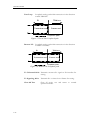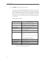
1
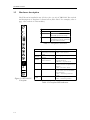
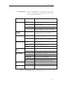
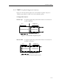
TAINET
MARS 9000
Trunk and DACS Module
ET1 9011/ET2 9012
Operation Manual
The Professional Partner
TAINET COMMUNICATION SYSTEM CORP.
Headquarters:
Beijing Branch:
No. 25, Alley 15, Lane 120, Sec. 1. Nei-Hu Rd.,
Taipei 114, Taiwan, R.O.C.
TEL: 886-2-26583000
FAX: 886-2-26583232
3F, A Building, 113 Zhi Chun Lu,
HaiDian District, Beijing, China
Zip Code: 100086
Tel: 86-10-62522081~87
Fax: 86-10-62522077
V1.2
07008-00046
2004/03/24
Contents
Chapter 1 INTRODUCTION
1.1 Functional Description ....................................................................... 1-2
1.2 Technical Information ........................................................................ 1-3
1.3 Hardware description ......................................................................... 1-4
Chapter 2 INSTALLATION
2.1
2.2
2.3
2.4
2.5
Unpacking .......................................................................................... 2-2
Installing ETx module........................................................................ 2-2
Configuring ETx parameters.............................................................. 2-3
Administrative Interface: LCD front panel ........................................ 2-4
ETx menu tree .................................................................................... 2-5
2.5.1
E1 CH SEL: Select E1 port for NMC 9000 operates............ 2-6
2.5.2
CONFIG E1: E1 main link parameters................................. 2-6
2.5.3
SYSTEM MANAGE: System level functions ..................... 2-8
2.5.4
DACS SET: Time slot interchange map.............................. 2-10
2.5.5
TEST: Loopback diagnostic functions .................................2-11
2.5.6
ALARM: Alarm indication functions.................................. 2-14
2.5.7
STATUS: System statistics functions .................................. 2-15
2.5.8
ERROR COUNT: Error count statistics............................. 2-17
Figure
Figure 1-1 ET1/ET2 9011B/9012B............................................................................ 1-2
Figure 1-2 ET1/ET2 9011U/9012U ........................................................................... 1-2
Figure 1-3 ET1/ET2 9011E/9012E ............................................................................ 1-2
Figure 1-4 ET1 9012U Faceplate............................................................................... 1-4
Figure 2-1 Module installation................................................................................... 2-2
Figure 2-2 Organization of ETx menu tree ................................................................ 2-5
Figure 2-3 Local Data Loopback path.......................................................................2-11
Figure 2-4 Remote Data Loopback path ...................................................................2-11
Figure 2-5 Local Line Loopback path...................................................................... 2-12
Figure 2-6 Remote Line Loopback path .................................................................. 2-12
Table
Table 1-1 Faceplate Connectors ................................................................................. 1-4
Table 1-2 Faceplate LED indicators........................................................................... 1-4
Table 2-1 ‘CONFIG E1’ group function .................................................................... 2-7
Table 2-2 Load Profile list.......................................................................................... 2-8
Table 2-3 SYSTEM MANAGE group function......................................................... 2-9
Table 2-4 TEST group function................................................................................ 2-13
Table 2-5 DACS SET group function ...................................................................... 2-14
Table 2-6 STATUS group function........................................................................... 2-16
Table 2-7 ERROR Count Object list ........................................................................ 2-17
Chapter 1
INTRODUCTION
Overview
1.1 Functional Description
1.2 Technical Information
1.3 Hardware description
1-1
INTRODUCTION
1.1
Functional Description
ETx 901x series are the aggregate link modules of MARS 9000 DSL
CONCENTRATOR. They provide the functionality of interface between the
system TDM bus and the E1 aggregate link. By utilizing this module, payload
from IDSL, MSDSL, MDSL, HDSL, and data port modules is aggregated to
backbone-network/hierarchy-ring for transportation and switching. Several
models are provided for variety of applications:
ET1 9011B:Single E1 port, Balanced mode G.703 interface (Mini terminal-block)
ET1 9011U:Single E1 port, Unbalanced mode G.703 interface (BNC connector)
ET1 9011E:Single E1 port, Unbalanced mode G.703 interface (Euro-style
Siemens 1.6/5.6 connector)
ET2 9012B:Dual E1 port, Balanced mode G.703 interface (Mini terminal-block)
ET2 9012U:Dual E1 port, Unbalanced mode G.703 interface (BNC connector)
ET2 9012E:Dual E1 port, Unbalanced mode G.703 interface (Euro-style
Siemens 1.6/5.6 connector)
ET1
ET1
ET2
SEL
SEL
SCAN
SCAN
1
SYNC
SEL
SCAN
2
SYNC
ET2
SEL
SEL
SEL
SCAN
SCAN
SCAN
1
SYNC
ET1
ET2
2
SYNC
1
SYNC
ALM
ALM
ALM
ALM
ALM
ALM
TEST
TEST
TEST
TEST
TEST
TEST
AIS
AIS
AIS
AIS
AIS
RX
RX
TX
TX
RX
TX
2
SYNC
AIS
RX
RX
RX
TX
TX
TX
RX
RX
TX
TX
RX
TX
EXT CLK
EXT CLK
EXT CLK
EXT CLK
EXT CLK
EXT CLK
CRAFT
CRAFT
CRAFT
CRAFT
CRAFT
CRAFT
RST
RST
RST
RST
RST
RST
9012U
9011E
9012E
9011B
9012B
Figure 1-1 ET1/ET2
9011B/9012B
9011U
Figure 1-2 ET1/ET2
9011U/9012U
Figure 1-3 ET1/ET2
9011E/9012E
Difference between models is the physical E1 interface (connector). They all
provide the same functionality for MARS 9000 system, and running the same
firmware code. We will use the name ETx to represent all these modules in
following sentences, except for special distinction.
1-2
INTRODUCTION
1.2
Technical Information
The E1 interface of ETx is fully comply with ITU-T recommendation G.703 and
G.704. This module supports configurable CRC-4 option to enhance
transmission integrity. E bit (Remote End Block Error bit) defined in ITU-T
Rec. G.704 is also supported, helping carrier with an easier solution to monitor
the E1 aggregate link. Physical interfaces of E1 links on ETx 901xU are
unbalanced, 75-ohm resistance, terminated by female BNC connectors. ETx
901xB with balanced, 120-ohm resistance, terminated by mini terminal-blocks.
ETx 901xE with unbalanced, 75-ohm resistance, terminated by Siemens 1.6/5.6
connectors.
The ETx module is Hot Swappable, which minimizes system downtime by no
power down insertion/replacement. Whenever there’s a need to re-initialize
hardware, reset switch can be reached on faceplate.
The MARS 9000 system is implemented with an in-built DACS (Digital Access
Cross-connect System). It supports comprehensive and flexible cross-connect
functionalities such as:
Ø
Ø
Ø
Ø
Interchange time-slot between E1 ports on the same ETx module.
Interchange time-slot between E1 ports and TDM buses.
Interchange time-slot between TDM buses on the same system.
Cross-connect between E1 ports and TDM buses (per 32 time-slot).
It reduces the cost for buying more ports on external DACS and utilizes E1
trunks at highest efficiency by managing local cross-connect traffic.
Due to the design of this in-built DACS function, no traffic can pass directly
from one tributary to another. All the data from tributaries must be forwarded to
TDM bus in order to be directed to the destination.
The timing mode of ETx can be one of three options: Recover from E11,
Generate internal clock and External clock. If more than one ETx modules are
coexisting on one MARS9000 system, only one of them can be in Master2 mode
and the others should be in Slave mode. An ETx in Master mode will be the
timing source of entire MARS 9000 system, including TDM bus and all other
tributaries. The other ETx in Slave mode will follow the clock from TDM bus.
The timing clock feeding into EXT CLOCK connector must be G.703 unframed
all ‘1’ signal and the acceptable accuracy is ±50 PPM (±5.0 x 10⁻⁵).
*Note
1
2
Refer to Clk Source Sel in section 2.5.3 SYSTEM MANAGE for
timing clock options
Refer to Clk Source Mode in section 2.5.3 SYSTEM MANAGE
for the necessary steps to setup an ETx in Master and Slave mode.
1-3
INTRODUCTION
1.3
Hardware description
The ETx can be installed in any I/O slot (slot 1 to 16) of TRS-32M. The outlook
and description of faceplate is shown below (ET1 9011U for example, refer to
page 1 for outlook of other models):
ET2
Connectors
EXT CLK
SCAN
1
Connector for E1 interface
Inlet of external SYSTEM
CLOCK (network clock)
RJ-45 phone jack socket for
connecting console terminal
RS-232 characteristics
TX / RX
SEL
2
SYNC
CRAFT
ALM
TEST
AIS
RX
Table 1-1 Faceplate Connectors
TX
RX
LED indicators
SEL
TX
SCAN
EXT CLK
SYNC
Selection indicator
selected by LCD front
panel
Indicator of polling
activity
E1 synchronization
status indicator
ALM
Alarm indicator
TEST
Test mode indicator
AIS
AIS indicator
CRAFT
RST
9012U
Figure 1-4 ET1 9012U
Faceplate
1-4
RED = Selected
OFF = Not selected
Blinking if polled by NMC-32
RED = Loss of
Synchronization
GREEN = Synchronized
RED = Alarm detected (read
section 2.5.4 for complete list of
alarms)
OFF = No active alarm
YELLOW = Test on going
(read section 2.5.3 for available
test functions)
OFF = Normal operational
mode
RED = AIS signal detected
OFF = Normal operation
Table 1-2 Faceplate LED indicators
Chapter 2
INSTALLATION
Overview
2.1 Unpacking
2.2 Installing ETx module
2.3 Configuring ETx parameters
2.4 Administrative Interface: LCD front panel
2.5 ETx menu tree
2.5.1
E1 CH SEL: Select E1 port for NMC 9000 operates
2.5.2
CONFIG E1: E1 main link parameters
2.5.3
SYSTEM MANAGE: System level functions
2.5.4
DACS SET: Time slot interchange map
2.5.5
TEST: Loopback diagnostic functions
2.5.6
ALARM: Alarm indication functions
2.5.7
STATUS: System statistics functions
2.5.8
ERROR COUNT: Error count statistics
2-1
INSTALLATION
2.1
Unpacking
Keep the packing box and/or shock-absorb material after unpacking ETx
modules. You may need them for safely shipping the module in the future. Rough
handling during shipping may cause module failure upon arrival. After unpacking,
check carefully for shipping damage. Contact the shipper if you notice any
damage.
2.2
Installing ETx module
The ETx module can be installed in any one of the TRS-32M slots. After it is
installed, the MARS 9000 controller will find it and start the initialization process
automatically.
When inserting this module into TRS-32M, hold the card on two screw knobs
and keep this card vertically to the floor (refer to the illustration below). Be sure
to fit the upper and bottom edge of card right in the slide-in trail before insertion
(it may crash the card if inserted without fitting in both trails). Slide this card
smoothly into chassis along the trail until bus connectors firmly fit into chassis
back plane. Double check if the card is inserted well then tighten the upper and
bottom screws by hand (to prevent from breaking the screw, tighten by a
screwdriver is not recommended).
Turn on the power supply unit with NMC-32 installed. The SCAN LED on
faceplate should start blinking in couple seconds. If it’s not blinking, please
recheck the card is correctly fitted into slot and reinstall again if necessary. If the
NO SCAN problem can’t be resolved or you have trouble installing the card,
please contact with your local dealer for technical support.
ETx
TRS-32M
Figure 2-1 Module installation
2-2
INSTALLATION
2.3
Configuring ETx parameters
By default, ETx was preset to operate on CCS mode (PCM31) which may be the
most common configuration for E1 connections. There are 4 factory profiles
hard-coded in the system, each of them defines one type of commonly used E1
configuration (a table is provided in PROFILE group at section 2.5.3 SYSTEM
MANAGE for selection). To successful setup E1 links on ETx module, all
necessary parameters must be clear and confirmed. If you don’t know some of
them, consult your network operator about the detail. In case the configuration
need to be changed, two administrative interfaces are supported:
l LCD front control panel of NMC 9000:
8 Full functional menu tree driven system.
8 2 x 16 character-LCD display with back light.
8 6 function buttons to switch between menu items and changing
configurations.
8 For detailed operation instructions, please
“Administrative interface: LCD front panel”
read
section
2.4
l Craft interface (Available soon)
8 Use a VT-100 or compatible emulator with communication parameters
set to “Asynchronous, 8 data bit, None parity bit, 1 stop bit” to launch
the craft user interface.
2-3
INSTALLATION
2.4
Administrative Interface: LCD front panel
Control of ETx trunk card can be reached via LCD front panel of NMC 9000.
This full-functional administrative interface provides you a feasible way to setup
parameters without additional facilities (ex. connecting a VT-100 terminal). For
detailed operational instructions, please refer to chapter ‘Introduction of LCD
front panel’ of ‘MARS9000 base system’ manual.
After ETx is selected on front panel, the brief state is reported on LCD. This
window gives prompt information of current E1 timing clock setting and E1 link
status as illustrated below:
C1MCK-INT
SYSTEM SYNC
C1
CK-CH1
SYSTEM SYNC
:
:
:
Port 1 is the selected for control operations on NMC 9000
Current timing clock is Master and Internal mode
Port 1 is synced with remote E1 equipment
Press [ENTER] button will lead you to the start of ETx menu tree. This menu
tree contains six groups, each provides specific configurable options or system
statistics. Understand each of them will help you set up the system more quickly
and is also required for designing a trouble-free network. Figure 1 shows the
organization of entire menu tree. Detailed information for each group will be
discussed later in section 2.5.
2-4
INSTALLATION
2.5
ETx menu tree
Higher Level
NMC Option
Password Edit
C1MCK-INT
SYSTEM SYNC
C1 MENU SELECT
E1 CH SEL
Lock
Front Lock
Unlock
Initial System
Are you sure?
Input: _ _ _ _
2: PCM31
1: PCM30C
20000119_1E1_2E1
S/W Ver:01.07
C1 MENU SELECT
SYSTEM MANAGE
Load Profile
0: PCM30
3: PCM31C
Trunk Bank Sel
CH 1,2,3,4
Clk Source Sel
Clk Source Mode
Ext
Int
Master
Slave
System Bus
E1 Ch2
E1 Ch1
C1 MENU SELECT
CONFIG E1
Shift
Right
EXIT
ENTER
Shift
Left
C1 MENU SELECT
ERROR COUNT
CRC
ON/OFF
Idle Code
0xff
Idle Ch. Sel. D
24..31: ________
Idle Ch. Sel. C
16..23 : ________
Idle Ch. Sel. B
08..15 : ________
Idle Ch. Sel. A
00..07 : ________
Rx MODE
CCS/CAS
Tx MODE
CCS/CAS
E BIT
AUTO/NONE
ALARM GEN
AIS/RALM/NONE
E BIT COUNT
Ext Clk Lost
CRC4 ERROR
Rx Dist MF Alarm
Rx Unframed All 1s
FAS ERROR
C1 MENU SELECT
ALARM
Clear All Alarm
Rx Lost of Sync
Rx signaling All 1s
It shows only if
Alarm was happen
C1 MENU SELECT
TEST
C1 MENU SELECT
STATUS
C1 MENU SELECT
DACS SET
Rx Remote Alarm
Rx Carrier Lost
System Error
Rx signaling All 0s
Data Loop
ON/OFF
Clear All Test
Are you sure?
TxSig All 1
ON/OFF
TxUnf All 1
ON/OFF
Remote LL
ON/OFF
Line Loop
ON/OFF
Remote DL
ON/OFF
Figure 2-2 Organization of ETx menu tree
2-5
INSTALLATION
2.5.1 E1 CH SEL: Select E1 port for NMC 9000 operates
This menu select one of the available E1 ports for operations on NMC
9000 front panel. As this function only works on multiple E1 capable
modules, this item takes no effect on model ET1.
Configurable objects:
E1 Channel 1:
Select the first E1 port for the control operations on
NMC 9000.
E1 Channel 2:
Select the second E1 port of ET2 card module for the
control operations on NMC 9000.
(Not available for model ET1)
2.5.2 CONFIG E1: E1 main link parameters
Below are functional descriptions for all configurable objects in
‘CONFIG E1’ group. Refer to table 2-1 for all available options.
Configurable objects:
CRC:
Turn on or off for CRC4 function. This option must
be identical on both end of E1 link or the link will not
work properly.
ALARM GEN: Select the method to generate alarm signal to notice
remote E1 equipment. Alarm signal will be generated
if any of following three conditions present:
1.
2.
3.
E BIT:
ETx can not synchronize with remote from received frames.
Receipt of AIS on E1 interface. (all ‘1’s)
No signal detected on E1 interface.
Switch on/off E bit function. E bit is the REBE bit
defined as bit 1 of frame 13/15 in time slot 0, it is
used to inform the remote system for local CRC error
event.
TX/RX MODE: Set E1 connection mode of TX/RX interfaces to CCS
or CAS mode. The value for TX and RX must be
identical to each other or the system will not work
properly.
Idle Ch. Sel. A/B/C/D :
2-6
Idle channel map for channel 0 to channel
31. Channels in Idle State will not be
allowed to pass any data.
INSTALLATION
Object name
CRC
Available
settings
ON
OFF (Default)
AUTO
ALARM GEN
AIS
Remote Alarm
None(Default)
AUTO
E BIT
NOT (Default)
CCS (Default)
CAS
Tx Mode
CCS (Default)
CAS
Rx Mode
Idle Ch Sel A Displayed as:
Idle Ch Sel B
00..07 ------Displayed as:
08..15 -------
Idle Ch Sel C Displayed as:
16..23 -------
Idle Ch Sel D Displayed as:
Idle Code
24..31 ------0xff
Description
Enable CRC function. All outgoing traffic will be
with CRC bits. Detected CRC error on incoming
traffic will be reported to ‘CRC4 Error Count’
under ‘ERROR COUNT’ group.
Disable CRC function.
Auto detecting CRC4 pattern from received multiframes. This function detects CRC4 pattern only
during E1 synchronizing phase. To apply this
option during service, E1 link must be manually
dropped for resynchronization.
Send AIS to notice remote. (All ‘1’ signal)
Set FAS distant alarm bit to inform remote
system for local alarm.
(This bit is the 3rd bit of NFAS in Time Slot 0,
defined in G.703 specification)
Do not generate any alarm.
Enable REBE bits function. CRC must be
enabled to have this option available.
To enable CRC function:
‘CONFIG E1’->’CRC’->’ON’
Ignore REBE bits.
Set Tx Mode to Common Channel Signaling
mode. (PCM31)
Set Tx Mode to Channel Associated Signaling
mode. (PCM30)
Set Rx Mode to Common Channel Signaling
mode. (PCM31)
Set Rx Mode to Channel Associated Signaling
mode. (PCM30)
‘-‘ hyphen sign represent a channel is activated
‘*’ star sign represent a channel is forced idle
Press [Enter] to switch the state
‘-‘ hyphen sign represent a channel is activated
‘*’ star sign represent a channel is forced idle
Press [Enter] to switch the state
‘-‘ hyphen sign represent a channel is activated
‘*’ star sign represent a channel is forced idle
Press [Enter] to switch the state
Note:Ch.16 is reserved under CAS mode
‘-‘ hyphen sign represent a channel is activated
‘*’ star sign represent a channel is forced idle
Press [Enter] to switch the state
Current version support fixed 0xff idle code
Table 2-1 ‘CONFIG E1’ group function
2-7
INSTALLATION
2.5.3 SYSTEM MANAGE: System level functions
Below are functional descriptions for all system administration objects in
this group. Refer to table 2-3 for all available options.
Available objects:
Load Profile:
CLK SEL
CRC
ALARM GEN
E BIT
TX/RX
MODE
Idle Ch. A~D
Idle Code
Note:
Reset system with pre-defined factory profiles.
Detailed information for each profile is listed in table
2-2.
Initial
E1
OFF
NONE
NONE
CCS
0:PCM30
E1
OFF
NONE
NONE
CAS
1:PCM30C
E1
ON
NONE
NONE
CAS
2:PCM31
E1
OFF
NONE
NONE
CCS
3:PCM31C
E1
ON
NONE
NONE
CCS
4: ~ 7:
reserved
reserved
reserved
reserved
reserved
NONE
0XFF
NONE
0XFF
NONE
0XFF
NONE
0XFF
NONE
0XFF
Reserved
Reserved
1.Load profile 0 through 3 or ‘Initial System’ will cause loss of user defined
parameters.
2.Profile 4 to 7 are left blank and reserved for future use.
Table 2-2 Load Profile list
Initial System:
Reset system and restore all configurable value to
factory default. Make sure this action is necessary
because all settings will be lost after command
executed.
Font Lock:
When front panel is ‘Locked’, operations on buttons
are still available for viewing statistics/settings. But
changing any parameter is prohibited. Therefore,
before making any changes, NMC 9000 must be in
‘Unlock’ state. By default, NMC 9000 front panel is
locked.
Password Edit:
Change the administrator’s password. This password
is used when unlocking front panel.
Clk Source Mode: Select the timing mode between ETx and TDM bus.
If Master mode selected, ETx will provide timing
clock to entire MARS 9000 system (TDM bus). If
Slave mode selected, ETx will follow the clock from
TDM bus. Only one Master is acceptable in one
MARS 9000 platform.
Clk Source Sel:
2-8
Select the timing source of ETx.
INSTALLATION
Trunk Bank Sel: Select the TDM bank to transport ETx traffic. Only
one out of two banks (4 * 32 time-slot bus) can be
chosen for each ETx module.
Object name
Available
settings
Load Profile 0: PCM30
Description
Default E1 settings for CAS(PCM30) mode
1: PCM30C
Default E1 settings for CAS(PCM30) mode with
CRC option enabled
2: PCM31
Default E1 settings for CCS(PCM31) mode
3: PCM31C
Default E1 settings for CCS(PCM31) mode with
CRC option enabled
Initial
System
Are you sure?
Reinitialize system to factory default (CCS mode). All
user defined parameters will be changed.
[ENTER]=’Yes’, [EXIT]=’No’
Front Lock
Lock
Lock front panel to prevent from unauthorized
changes on configuration
Unlock
Unlock front panel. Password is required to release
the lock.
Password Edit Input : ----
Clk Source
Mode
Clk Source
Sel
Trunk Bank
Sel
E1 Connect
Sel
Step 1: Input administrative password for
authentication
Edit : ----
Step 2: Enter new password
Verify : ----
Step 3: Re-enter new password again for verification
Master
Set the module as the clock source of MARS 9000
system
Slave
Follow timing clock from TDM bus
E1 Ch1
Recover clock from 1st E1 port
E1 Ch2
Recover clock from 2nd E1 port
System Bus
Follow timing clock from TDM bus
Int
Generate clock signal
Ext
Follow clock signal from EXT CLK interface
Ch 1,2,3,4
Select bank 1 (TDM bus 1~4) as transport medium.
Ch 5,6,7,8
Select bank 2 (TDM bus 5~8) as transport medium.
Refer to instruction above
Table 2-3 SYSTEM MANAGE group function
2-9
INSTALLATION
2.5.4 DACS SET: Time slot interchange map
This group contains all time slot interchange mapping information of all
E1s and TDM bus on the same ETx. Each entry of this map contains
following four items:
Available objects:
Source time slot
Target time slot
State
Command
‘Source time slot’ is expressed as:
EPn:xx, where n is the E1 port number, xx is the time-slot number of
E1. Or TDn:xx, where n is the TDM bus number, xx is the time-slot
number of TDM bus.
‘Target time slot’ is expressed as:
EPn:xx, where n is the E1 port number, xx is the time-slot number of
E1. Or TDn:xx, where n is the TDM bus number, xx is the time-slot
number of TDM bus
‘State’ is expressed as:
D*/ß
C*/ß
Disconnect (disabled entry/disconnect target and source)
Connect (effective entry/connect target and source)
‘Command’ is the action to execute current setting. Valid commands are:
Do not apply the change (pressing [ENTER] with this symbol will not
apply any change of the entry)
ß Apply this entry
(this symbol will show only during front panel
operation. After the entry is applied, this symbol
will return to ‘*’ as normal state)
Example:
*
Cross-connecting between time slot 05 of the 1st E1 and time slot 13 of
the 2nd E1:
EP1:05 EP2:13 Cß
Disable an entry:
EP2:30 TD2:15 Dß
Cross-connecting between time slot 10 of the 1st E1 and time slot 25 of
TDM bus 6:
EP1:10 TD6:25 Cß
*Note:
If the assigned time slot in a new entry is occupied by other entries, the controller
will notice operator by displaying ‘Error Setting’, and no changes will be applied.
2-10
INSTALLATION
2.5.5 TEST: Loopback diagnostic functions
Below are functional descriptions for all available loopback objects in
‘TEST’ group. Refer to table 2-4 for all available options.
Configurable objects:
Data Loop:
Loopback digital data path within framer in the direction
toward TDM bus.
E1
TDM bus
Transceiver end
Framer end
Loopback path
Figure 2-3 Local Data Loopback path
Remote DL: Loopback digital data path within framer in the direction
toward E1 interface.
E1
TDM bus
Transceiver end
Framer end
Loopback path
Figure 2-4 Remote Data Loopback path
2-11
INSTALLATION
Line Loop:
Loopback analog path within transceiver in the direction
toward TDM bus.
E1
TDM bus
Transceiver end
Framer end
Loopback path
Figure 2-5 Local Line Loopback path
Remote LL: Loopback analog path within transceiver in the direction
toward E1 interface.
E1
TDM bus
Transceiver end
Framer end
Loopback path
Figure 2-6 Remote Line Loopback path
Tx Unframed All 1s: Transmit constant all 1 signal on E1 interface for
testing.
Tx Signaling All 1s: Transmit all 1 on time slot 16 frames for testing.
Clear All Test:
2-12
Clear all active test and return to normal
operational mode.
INSTALLATION
Object name Available
settings
Data Loop
Remote DL
Line Loop
Remote LL
TxUnf All 1
TxSig All 1
Description
On
Force data loop for local testing
Off
Cancel Data Loop
On
Force data loop for remote testing
Off
Cancel Remote Data Loop
On
Force line loop for local testing
Off
Cancel Line Loop
On
Force line loop for remote testing
Off
Cancel Remote Line Loop
On
Transmit constant all 1 signal on E1 interface
Off
Cancel this test
On
Transmit constant all 1 signal on E1 time slot 16
Off
Cancel this test
Clear All
Test
Table 2-4 TEST group function
2-13
INSTALLATION
2.5.6 ALARM: Alarm indication functions
This group is hot popping and triggered by occurrence of alarm. If no
active alarm presents, this group will become invisible from menu tree.
Objects shown in this group are active alarms. This group contains only
one user operational option as ‘Clear All Alarm’ which will clear all
alarms history and start display new alarm. Below are functional
descriptions for all alarm indication objects in ‘ALARM’ group. Some of
the alarm will only occur under CAS mode, and they will be mentioned in
the description.
Alarm indication objects:
Object name
Description
Rx signaling All 1s Receipt of All ‘1’s on time slot 16 under CAS mode.
This usually indicates transmission trouble.
Rx signaling All 0s Receipt of All ‘0’s on time slot 16 under CAS mode.
This usually indicates transmission trouble.
Ext Clk Lost
Absence of EXT CLOCK signal.
Rx Dist MF Alarm
Remote SYNC LOSS indicator. This alarm will only
occur under CAS mode.
Rx unframed All 1s
Receipt of AIS on E1 interface.
Rx Remote Alarm
Remote alarm indicator. This alarm occurs when one
of following three condition presents on remote E1
equipment:
1. Can not synchronize with local ETx from received
frames.
2. Receipt of AIS on E1 interface. (all ‘1’s)
3. No signal detected on E1 interface.
Rx Carrier Loss
Absence of Rx signal
Rx Lost of Sync
Local SYNC LOSS indicator.
System Error
ETx module failure indicator.
Clear All Alarm
Clear all alarm history.
Table 2-5 DACS SET group function
2-14
INSTALLATION
2.5.7 STATUS: System statistics functions
This group provides administrator a quick system status overview. Some
of the objects are E1 link status and the others are most important E1
related configurations set in specific group. Table 2-6 lists all objects and
their possible messages.
System statistics objects:
SYNC = :
Synchronization status of ETx E1 interface.
CLK SEL:
ETx clock source selection. Refer to ‘CONFIG E1’
group for detailed information.
CRC SET:
Active setting of CRC option. Refer to ‘CONFIG E1’
group.
Alarm Gen:
Active setting of alarm generation options. Refer to
‘CONFIG E1’ group.
E BIT:
Active setting of E Bit treatment. Refer to ‘CONFIG
E1’ group.
Tx/Rx Mode:
Active E1 link type of Tx/Rx interface. Refer to
‘CONFIG E1’ group.
2-15
INSTALLATION
Object name
SYNC =
CLK SEL
CRC Set
Alarm Gen
Available
Message
Description
SYSTEM SYNC
E1 trunk is synchronized with remote system
NO CARRIER
No signal detected on E1 interface
FAS LOSS
Loss of frame alignment. This indicates E1 link
error and is reported when trunk card received
incorrect Frame Alignment Signal.
CAS LOSS
Failed to synchronize with remote system on
signaling (time slot 16) channel under CAS mode.
This indicates an error on E1 link.
CRC LOSS
CRC error detected on received data. This will
only occur when CRC option is enabled. When
CRC LOSS occurs, E1 link could still work with
lower accuracy, depend on the real error rate.
E1
Follow recovered clock from E1.
‘CONFIG E1’->‘CLK SEL’->‘E1’
INT
Generate timing clock with internal oscillator.
‘CONFIG E1’->‘CLK SEL’->‘INT’
EXT
Follow external clock from EXT CLOCK
connector
‘CONFIG E1’->‘CLK SEL’->‘EXT’
ON
CRC4 function enabled
‘CONFIG E1’->’CRC’->’ON’
OFF
CRC4 function disabled
‘CONFIG E1’->’CRC’->’OFF’
AUTO
CRC4 semi-auto function enabled
‘CONFIG E1’->’CRC’->’AUTO’
NONE
‘CONFIG E1’->’Alarm Gen’->’None’
AIS
‘CONFIG E1’->’Alarm Gen’->’AIS’
Remote Alarm ‘CONFIG E1’->’Alarm Gen’->’RALM’
E Bit
Tx Mode
Rx Mode
NONE
‘CONFIG E1’->’E BIT’->’None’
Auto
‘CONFIG E1’->’E BIT’->’Auto’
CCS
‘CONFIG E1’->’Tx Mode’->’CCS’ (PCM31)
CAS
‘CONFIG E1’->’Tx Mode’->’CAS’ CM30)
CCS
‘CONFIG E1’->’Rx Mode’->’CCS’ (PCM31)
CAS
‘CONFIG E1’->’Rx Mode’->’CAS’ CM30)
Table 2-6 STATUS group function
2-16
INSTALLATION
2.5.8 ERROR COUNT: Error count statistics
Errors count objects:
This group provides administrator a reference to detected transmission
error counts. This error-count objects will count the statistic error during
one second, and is restarted every second. Table 2-7 lists all objects.
CRC4 Error Count: Counter that counts detected CRC4 errors. This
counter will restart at every second and will stop counting during E1
SYNC LOSS.
E Bit Count: Counter that reports the received E Bits from remote
equipment. This counter will restart at every second and will stop
counting during E1 SYNC LOSS.
FAS Error Count: Counter that counts Frame Alignment Signal error
words. This counter will restart at every second.
Object name
Description
CRC4 Error Count Detected CRC4 errors per second.
Len.
10
E Bit Count
Received E Bit count per second.
10
FAS Error Count
Detected FAS error counts per second on received frames.
12
Len. : Size of counter in bits.
Table 2-7 ERROR Count Object list
2-17
INSTALLATION
This page is intentionally left blank.
2-18