1
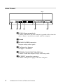
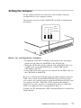
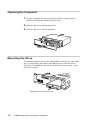
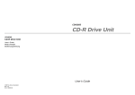
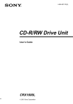
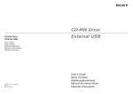
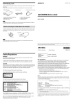
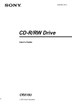
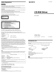
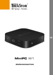
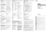
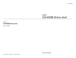
3-865-162-11(3)
CRX100E
CD-R/RW Drive Unit
User’s Guide
Owner’s Record
The model and serial numbers are located on the top of the drive. Record these numbers
in the spaces provided below. Refer to them whenever you call upon your sales representative regarding this product.
Model No.
Serial No.
Safety Regulations
WARNING
To prevent fire or shock hazard, do not expose the unit to rain or moisture.
To avoid electrical shock, do not open the cabinet. Refer servicing to qualified personnel
only.
CAUTION
As the laser beam in this CRX100E is harmful to the eyes, do not attempt to disassemble
the cabinet. Refer servicing to qualified personnel only.
The use of optical instruments with this product will increase eye hazard.
The use of controls or adjustments or performance of procedures other than those
specified herein may result in hazardous radiation.
DANGER
INVISIBLE LASER RADIATION WHEN OPEN.
AVIOD DIRECT EXPOSIRE TO BEAM
VORSICHT
UNSICHTBARE LASERSTRAHLUNG. WENN ABDECKUNG
GEOFFNET
NICHT DEMSTRAHL AUSSETZEN.
This label is located on the drive unit’s internal
chassis.
Dieses Etikett befindet sich auf dem inneren Chassis
des Laufwerkes.
INVISIBLE LASER RADIATION WHEN OPEN.
AVOID DIRECT EXPOSURE TO BEAM.
RADIATIONS INVISIBLES DU LASER EN CAS D'OUVERTURE.
EVITER TOUTE EXPOSITION DIRECTE AU FAISCEAU.
VORSICHT UNSICHTBARE LASERSTRAHLUNG, WENN ABDECKUNG GEÖFFNET.
NICHT DEM STRAHL AUSSET ZEN.
ADVARSEL USYNLIG LASERSTRÅLING VED ÅBNING.
UNDGÅ UDS/ETTELSE FOR STRÅLING.
DANGER
DANGER
ADVARSEL USYNLIG LASERSTRÅLING NÅR DEKSEL ÅPNES.
UNNGÅ EKSPONERING FOR STRÅLEN.
VARNING
OSYNLIG LASERSTRÅLING NÅR DENNA DEL AR ÖPPNAD.
STRÅLEN ÄR FARLIG.
VAROI
NÄKYMÄTÖN AVATTAESSA OLET ALTTINA LASERSÄTEILYLLE.
ÄLÄ KATSO SÄTEESEN.
This label is located on the top of the drive unit enclosure.
Dieses Etikett befindet sich am Boden des Laufwerksgehäuses.
2
This unit uses CD-RW discs with the following mark.
This unit uses CD-R discs with the following mark.
This unit uses CD-ROM discs with the following mark.
When you use this unit as a CD player, use compact
discs with the following mark.
WARNING — For the customers in U.S.A.
You are cautioned that any changes or modifications not expressly approved in this
manual could void your authority to operate this equipment.
Note:
This equipment has been tested and found to comply with the limits for a Class B digital
device, pursuant to Part 15 of the FCC Rules. These limits are designed to provide
reasonable protection against harmful interference in a residential installation. This
equipment generates, uses, and can radiate radio frequency energy and, if not installed
and used in accordance with the instructions, may cause harmful interference to radio
communications. However, there is no guarantee that interference will not occur in a
particular installation. If this equipment does cause harmful interference to radio or
television reception, which can be determined by turning the equipment off and on, the
user is encouraged to try to correct the interference by one or more of the following
measures:
- Reorient or relocate the receiving antenna.
- Increase the separation between the equipment and receiver.
- Connect the equipment into an outlet on a circuit different from that to which the
receiver is connected.
- Consult the dealer or an experienced radio/TV technician for help.
CLASS 1
LASER PRODUCT
LASER KLASSE 1
PRODUKT
This CD-R/RW drive unit is classified as a CLASS 1
LASER PRODUCT.
The CLASS 1 LASER PRODUCT label is located at the
top of the enclosure.
Bei diesem CD-R/RW-Laufwerk handelt es sich um ein Laser-Produkt der Klasse 1.
Das Etikett mit der Aufschrift LASER KLASSE 1 PRODUKT befindet sich auf der
Oberseite des Gehäuses.
3
Declaration of Conformity
Trade Name:
Model No.:
Responsible Party:
Address:
Telephone No.:
SONY
CRX100E
Sony Electronics Inc.
1 Sony Drive, Park Ridge, NJ. 07656 USA
201-930-6970
This device complies with Part 15 of the FCC Rules. Operation is subject to the
following two conditions:
(1) This device may not cause harmful interference, and
(2) This device must accept any interference received, including interference that may
cause undesired operation.
Trademarks
• MS-DOS is a registered trademark of Microsoft Corporation.
• IBM PC, PC/XT, and PC/AT are registered trademarks of International Business
Machines Corporation.
• HP Vectra is a registered trademark of the Hewlett-Packard Company.
• Molex is a registered trademark of Molex, Inc.
• AMP is a registered trademark of AMP, Inc.
4
Contents
Introduction
6
Location and Function of Parts and Controls
7
Front Panel ......................................................................................... 7
Rear Panel .......................................................................................... 8
Precautions
9
Example of System Setup
10
Installing the Drive in Your Computer
10
Preparation ....................................................................................... 10
Setting the Jumpers .......................................................................... 11
Opening the Computer ..................................................................... 12
Mounting the Drive ........................................................................... 12
Connecting the Drive ........................................................................ 13
Mounting the Host Adapter ............................................................... 16
Closing the Computer ....................................................................... 16
Installing the Software Driver
17
Using Discs
17
Storing Discs .................................................................................... 17
Care of Discs .................................................................................... 17
Operating the Drive
18
Starting the Drive .............................................................................. 18
Ejecting the Disc ............................................................................... 20
How to Use the Disc Locks ............................................................... 21
Specifications
23
5
Introduction
Features
The CRX100E is an internal CD-R/RW (Compact Disc Recordable/
ReWritable) drive unit designed for use with an IBM PC, HP Vectra,
or compatible computer.
It can write as much as 650 Mbytes of digital data into CD-R disc,
and can read as much as 650 Mbytes of digital data stored in a CDROM (Compact Disc Read-Only Memory), CD-R and CD-RW disc.
The CRX100E has the following features:
General
• 5 1 /4 inch half-height drive form factor.
• Audio CD like tray loading of a disc without using a caddy.
• Power loading and power eject of a disc. The disc can also be
ejected manually.
• Housed in a casing with an airtight frame.
• 1 Mbyte buffer memory on the ATA controller.
• Supports Power saving mode and Sleep mode.
Supported disc formats
• Reads and writes data in each CD-ROM, CD-ROM XA, CD-I,
CD-I Ready, Video CD, CD-EXTRA, and CD-TEXT.
• Reads data in Photo CD (Single and Multi session).
• Reads and writes standard CD-DA.
• Reads and writes CD-R discs conforming to “Orange Book Part
II”.
• Reads and writes CD-RW discs conforming to “Orange Book Part
III”.
Supported write method
• Disc at once, Session at once, Track at once, Variable packet,
Fixed packet and Multi-session.
P erf or m a n c e
• Supports CD-R write operation at each standard speed, double
speed and quadruple speed.
• Supports CD-RW write operation at double speed.
• Supports read-only operation at max 24 times speed.
• Supports real time error correction and real time layered error
correction at each speeds.
• Fast access time ensuring reliable high-speed data access.
Audio
• Outputs 16-bit digital data over the ATA interface.
• Equipped with audio line output and headphones jack for audio
CD playback.
■ Software requirement
Install the appropriate application software before using this unit.
6
Introduction
Location and Function of Parts and Controls
Front Panel
1
6
5
2
4
3
1 Disc tray
Accepts a CD-ROM, CD-R and CD-RW disc on its tray.
2 Emergency eject hole
Insert a fine rod into this hole to eject the tray manually in
emergencies.
3 Eject button
Opens and closes the disc tray.
4 Busy indicator
This indicator shows the unit’s status in various phases of
operation.
* Seek, read and write: Flashes amber
* Error:
Lights up amber and stays lit
5 Volume control
Controls the volume of the analog audio output provided via a
headphones jack.
6 Headphones jack
Provides two channel analog audio output.
Location and Function of Parts and Controls
7
Rear Panel
Pin 1
1
2 3
4
5
6
1 F.GND (Frame ground) tab
Connect with one of the host computer’s ground cables when the
drive’s frame is not in direct contact with the computer.
2 Unused
3 ANALOG AUDIO connector
Outputs analog audio signals.
4 Configuration Jumpers
See page 11 for details.
5 INTERFACE CONNECTOR (IDE bus)
Connect to IDE host adapter using a connecting cable.
6 DC INPUT (power-in) connector
Connect to the power supply of the host computer.
8
Location and Function of Parts and Controls
Precautions
■ Installation
• Avoid placing the drive in a location subject to:
– high humidity
– high temperature
– excessive dust
– mechanical vibration
– direct sunlight.
We recommend to use the drive in a horizontal or vertical position.
Do not use it in a tilted position.
■ Operation
• Do not move the drive during operation. This may cause it to
malfunction during reading or writing.
• Avoid exposing the drive to sudden changes in temperature as
condensation may form on the lens inside the drive as a result.
Should the surrounding temperature suddenly rise while the drive
is on, wait at least one hour before you turn off the power.
Operating the drive immediately after a sudden increase in
temperature, may result in a malfunction during reading or
writing.
■ Transportation
• Close the disc drawer before moving the drive.
• Keep the original packing materials for future transport of the
drive.
Precautions
9
Example of System Setup
To use the CD-R/RW device, the following components are
required:
• Computer (IBM-PC/AT, HP Vectra, or equivalent)
• IDE Host adapter (ATA compliant)
• Floppy disc drive
• IDE Interface cable (40 to 40 pin flat cable)
• Software (Device driver, utilities)
Installing the Drive in Your Computer
This section provides an example of instruction for installing the
CD-R/RW drive unit into your personal computer using the IDE
Host Adaptor (ATA-Compliant).
To connect the CRX100E directly to the PC’s IDE port, consult
your PC manufacturer for instruction.
Preparation
You need the following parts and tools (these are not supplied with
the drive):
• A flat-blade screwdriver
• Four screws 3 mm in diameter and 6 mm in length.
• Two mounting rails if your computer has mounting tracks.
Unplug the computer and disconnect the cables attached to the back
to give yourself more room to work. Do not turn on the power of the
computer before completing the entire installation process.
10
Example of System Setup / Installing the Drive in Your Computer
Setting the Jumpers
Set the jumpers on the rear of the drive in accordance with the
configuration of your computer system.
The jumpers are preset at the “MASTER” position as illustrated at
the factory.
CSEL
SLAVE
MASTER
Notes for configuration jumpers:
• Designation of the Drive Number is generally set by inserting a
jumper pin on either the MASTER or the SLAVE pin.
• When the CRX100E is daisy-chained with a Hard Disk Drive on
an IDE Card, set the Hard Disk Drive as MASTER and the
CRX100E as SLAVE.
• If the CRX100E is the only device connected to the IDE Card, set
the CRX100E as MASTER.
However, it should be noted that some personal computers may use
CSEL in lieu of the foresaid MASTER/SLAVE selection. In this
case, remove the existing jumpers from MASTER and SLAVE, and
set a jumper on CSEL. When the CSEL signal of the interface
connector is set low, the drive is designated as Drive 0. When the
CSEL is set high, the drive is designated as Drive 1.
Consult your PC manufacturer, IDE Card manufacturer or dealer for
further details.
Installing the Drive in Your Computer
11
Opening the Computer
1 If your computer has its rear side covered by a plastic panel
attached with plastic hook pad, pull it off.
2 Remove the cover mounting screws.
3 Remove the cover of the computer.
Mounting the Drive
If mounting rails are necessary, attach them to the drive in the same
way as your floppy disk drive and slide the drive into the lower
drive bay. If mounting rails are not required in your system, screw
the drive in place.
Slide the drive into the lower bay.
12
Installing the Drive Unit into the Computer
Connecting the Drive
Connect the drive to the computer with the following connectors:
• DC INPUT connector
• AUDIO OUT connector (if you plan to connect audio equipment)
• INTERFACE CONNECTOR.
INTERFACE CONNECTOR
DC INPUT connector
AUDIO OUT
connector
■ DC INPUT connector
The pin assignment is as follows.
GND
+5 V DC
+12 V DC
After matching the beveled edges, insert the plug of the power
supply cable to the DC INPUT connector and push it firmly in place.
Caution: Improper connection may damage the drive and void the
warranty.
DC INPUT connector
Power supply cable
(4-pin connection cable)
Installing the Drive Unit into the Computer
13
■ Frame ground
When normally installed, the drive unit is not in contact with the
host computer directly and should be grounded. Connect the frame
ground tab to one of the host computer’s ground cables.
Frame ground tab
Frame ground cable
The frame ground cable recommended has a AMP 1-480435-0
housing and 170203-2 or 60711-1 contacts.
14
Installing the Drive Unit into the Computer
■ AUDIO OUT connector
The pin assignment is as follows:
pin
1
2
3
4
Audio Signal
R signal
ground
ground
L signal
■ INTERFACE CONNECTOR
1 Firmly insert one end of the interface cable into the INTERFACE CONNECTOR.
Pin 1
INTERFACE
CONNECTOR
INTERFACE cable
2 Attach the other end of the cable to the host adapter.
Host adapter
INTERFACE cable
Installing the Drive Unit into the Computer
15
Mounting the Host Adapter
Install the host adapter in one of the available system expansion
slots of your computer. Refer to the operating instructions included
with the host adapter for complete instructions on installation and
settings.
Install the host adapter in
one of the expansion slots.
Closing the Computer
1 Replace the cover on the computer, being careful to reinstall all
screws that were removed.
2 Replace the AC power cord and turn on your computer.
16
Installing the Drive Unit into the Computer
Installing the Software Driver
MSCDEX and the device driver for an ordinary CD-ROM drive can
be used when using the CRX100E as a CD-ROM drive.
Use the device driver for a CD-R/RW drive when using the
CRX100E as a recordable or rewritable drive.
Be sure to install the device driver before operating the drive. Refer
to the manual supplied with the host adapter for instructions.
Using Discs
Storing Discs
• Do not store the disc in a location subject to:
– high humidity
– high temperature
– excessive dust
– direct sunlight
Care of Discs
• Hold the disc by its edge. Do not touch the surface.
• Wipe the CD-ROM disc with the optional CD cleaner to clean it.
• Do not wipe a CD-R disc and CD-RW disc with a cleaner before
recording data. To avoid scratching the recording surface, blow
away dust using an air blower.
• Data cannot be recorded if the recording surface is contaminated.
Installing the Software Driver / Using Discs
17
Operating the Drive
This section describes how to start the drive and eject a disc.
Starting the Drive
1 Turn on the power of your computer.
2 Press the eject button.
The tray comes out automatically.
3 Place a disc in the tray with its label side up.
18
Operating the Drive
Note:
When the drive is set up in vertical position, use the disc locks to
prevent your disc from falling. See “How to Use the Disc Locks” on
page 21 for details.
Disc locks
4 Gently push the tray or press the eject button to close the tray.
The drive may begin reading the Table of Contents (TOC) data
when it accepts the disc. The busy indicator lights up in amber
while the drive is reading the TOC.
When the busy indicator lights out, the drive is ready to receive
commands, and data may be retrieved from the disc.
After loading the CD-R or CD-RW disc, it takes a moment for
the drive to become ready while the Program Memory Area is
read.
For subsequent drive operations, follow the instructions provided
with the application software you are using.
Note:
The busy indicator stays lit in amber if:
– the disc is not properly placed on the loading tray
– a malfunction occurs.
In either case, eject the disc and place it in the loading tray again
making sure that it sits properly in the tray. If doing this does not
solve the problem and the busy indicator still remains lit in amber,
consult your dealer or qualified service personnel.
The busy indicator also lights amber during audio play. However,
this is not a malfunction.
Caution: Do not forcibly close the disc drawer. Applying excessive
force may damage the loading mechanism. The tray’s mechanism is
designed to operate with a “feather touch”.
Operating the Drive
19
Ejecting the Disc
To eject the disc, press the eject button on the front panel. The tray
comes out automatically.
Note:
The eject button does not work if it is disabled by the software you
are using.
■ Opening the tray manually in an emergency
You can open the tray manually when it fails to come out by means
of the eject button or software commands. To do this, follow the
procedure below:
1 Turn off the power of your computer.
2 Insert a pointed object, such as a paper clip, into the emergency
eject hole and push.
Approx. 40 mm
After removing a disc from the drive unit, consult your dealer or
qualified service personnel.
20
Operating the Drive
How to Use the Disc Locks
The disc tray has four disc locks that prevent the disc from falling
when the drive is set up in vertical position.
Disc locks
Note:
When the drive is used in horizontal position, you do not need to
lock the disc.
■ Locking and unlocking
All of the four locks are set in the unlocked position (facing
outward) when the drive is shipped from the factory. To set the lock
in the locked position, turn it with your fingers until you hear a click
so that it faces inward.
locked
to unlock
unlocked
to lock
Operating the Drive
21
When the drive’s right side is down
To facilitate disc handling, set the disc locks B, C and D into the
locked position, and leave the disc lock A in the unlocked position.
A
D
Top side
Right side
B
C
When the drive’s left side is down
To facilitate disc handling, set the disc locks A, C and D into the
locked position, and leave the disc lock B in the unlocked position.
C
B
Top side
Left side
D
22
Operating the Drive
A
Specifications
■ General
Host interface
Read Function
Acceptable discs:
Write Function
Applied Format:
Writing Method:
Cache memory(R/W)
Disc diameter:
Rotational speed
Innermost track:
ATAPI compliant
CD-ROM mode-1 data discs
CD-ROM XA discs
CD-Audio discs
Audio-combined CD-ROM discs
CD-I discs
CD-I Ready Discs
Photo CD (Single and Multi session)discs
Video CD discs
CD-EXTRA discs
CD-TEXT discs
CD-R discs (Conforming to
“Orange Book Part II”)
CD-RW discs (Conforming to
“Orange Book Part III”)
CD-ROM Mode-1
CD-ROM XA
CD-Audio
Audio-combined CD-ROM
CD-I
Video CD
CD-EXTRA
CD-TEXT
Disc at once
Session at once
Track at once
Variable packet writing
(Packet size : max. 1 Mbyte)
Fixed packet writing
(Packet size : max. 1 Mbyte)
Multi-session
1 Mbyte
12 cm(8cm Read Only)
600 min-1 (600 rpm) at CLV = 1.4 m/s
(1×)
1200 min-1 (1200 rpm) (2×)
2400 min-1 (2400 rpm) (4×)
4800 min-1 (4800 rpm) (8×)
5000 min-1 (5000 rpm) at CAV 10×
Specifications
23
Outermost track:
200 min-1 (200 rpm) at CLV = 1.2 m/s
(1×)
400 min-1 (400 rpm) (2×)
800 min-1 (800 rpm) (4×)
1600 min-1 (1600 rpm) (8×)
5000 min-1 (5000 rpm) at CAV 24×
■ Drive performance
Data transfer rate
Sustained rate:
Burst rate:
Access time
Random stroke:
150 kbytes/s (1×)
300 kbytes/s (2×)
600 kbytes/s (4×)
1200 kbytes/s (8×)
1500 to 3600 kbytes/s 10 to 24× CAV
16.6 Mbytes/s (PIO Mode 4)
16.6 Mbytes/s (Multiword DMA Mode 2)
150 ms (typical/10 to 24× CAV)
■ Reliability
Read error rate (includes retry, normal disc)
L-EC on:
1 Block / 1012 bits (double)
L-EC off:
1 Block / 109 bits (double)
■ Audio
Output level
Line out:
Head phone:
0.75 V at 47 k Ω
0.55 V at 32 Ω
■ Environmental conditions
Temperature and humidity
Operating
5 °C to 45 °C(41°F to 113 °F)
(no condensation)
Transportation
–40 °C to 60 °C(–40 °F to 140 °F),
10 % to 90 % (within 72 hours,
no condensation)
Storage
–30 °C to 50 °C(–22 °F to 122 °F,
10 % to 90 % (within 6 months,
no condensation)
Temperature and
humidity gradients
10 °C/hour, 10 %/hour
24
Specifications
Vibration
Operating
Non-operating
Transportation
Shock
Operating
Non-operating
Transportation
■ Dimensions and weight
Dimensions
Mass
Read: 1.96 m /s2 (0.2 G o-p) at 5 Hz to
300 Hz (sweep)
Write: 0.98 m /s2 (0.1G o-p) at 5Hz
to 300 Hz(sweep)
19.6 m /s2 (2 G o-p) at 7 Hz to 300 Hz
1.44 m2 /s3 -Hz (0.015 G2 /Hz) at 5 Hz to
50 Hz
Read: 49 m /s2 (5 G o-p) at 11 ms half
sine wave (includes 5 retries)
Write:4.9 m/s2 (0.5 G o-p) at 11ms half
sine wave
490 m /s2 (50 G o-p) at 11ms half sine
wave
76 cm drop (with standard individual
package)
146.0 x 41.4 x 203.0 mm ( w / h / d )
(5 3/4 x 1 5/8 x 8 inches)
940 g
■ Power requirement
Voltage
Ripple
Current
Hold track state
+5 V ± 5 % DC and +12V DC ± 10 %
+5 V: 0.05 Vp-p
+12 V: 0.1 Vp-p
+5 Vdc
+12 Vdc
Seeking
+5 Vdc
+12 Vdc
Spin up/Write
+5 Vdc
+12 Vdc
Sleep
+5 Vdc
+12 Vdc
800 mA (Typ)
< 1000 mA (Max)
200 mA (Typ)
< 400 mA (Max)
800 mA (Typ)
< 1200 mA (Max)
300 mA (Typ)
< 800 mA (Max)
800 mA (Typ)
< 1200 mA (Max)
500 mA (Typ)
< 800 mA (Max)
90 mA (Typ)
< 120 mA (Max)
0.2 mA (Typ)
< 0.3 mA (Max)
Specifications
25
■ Connectors
Power-in/Interface/ID Jumper Switch/Audio connector
IRISO IMSA-9012B-55Z01-GT
Recommended Mating (Female) Connectors
for POWER connector
AMP 1-480424-0 or equivalent
(Pin Header: AMP 170147-1 or 4 AWG24-18 / AMP 170120-1 or
4 AWG20-14)
for INTERFACE connector and 2 pin out connector
AMP 746285-9 or equivalent
for AUDIO connector (4pin)
Molex 70066C or G, 70430C or G,
70430C or G, or equivalent
Note: 70066C and 70430C are without
latch type
70066G and 70430G are with latch
type
for GROUND TAB
Housing: AMP 1-480435-0
Contact: AMP170203-2 or 60711-1
■ Laser
Type
Wave length
Output power
Semiconductor laser GaAlAs
778 to 787nm (at 25 ˚C ± 2 ˚C)
4.0 mW (Read)
80 mW (Write)
■ Supplied accessory
User’s Guide
(1 each)
■ Optional accessories
CD ROM discs:
YHDS-50 “CD-ROM Test Disc Type 1.3”
(equivalent to YHDS-4)
YHDS-100 “CD-ROM Test Disc Type
2.0" (audio-combined)
■ Crystal frequency
33.868 MHz
34.574 MHz
17.287 MHz
46.000 MHz
Design and specifications are subject to change without notice.
26
Specifications
Diese Ausrüstung erfüllt die Europäischen EMC-Bestimmungen für die Verwendung in
folgender / folgenden Umgebung(en):
• Wohngegenden
• Gewerbegebiete
• Leichtindustriegebiete
(Diese Ausrüstung erfüllt die Bestimmungen der Norm EN55022, Klasse B.)
■ Dimension diagram
+0.05
146 -0.45
41.4 ±0.5
21.9 ±0.5
139.7 ±0.5
±0.5
(0.5)
0.5
4-M3 MOUNTING HOLES
42.3 ±0.5
148
5 ±0.5
47.5 ±0.5
79.25 ±0.5
203 ±0.5
74.25 ±0.5
10 ±0.5
4-M3 MOUNTING HOLES
(4 ON EACH SIDE)
Important:
Screws must not extend more than 6.0mm into the side panels or the
bottom plate.
Specifications
27
CRX100E
CD-R/RW Drive Unit
User’s Guide
©1998 by Sony Corporation
Printed in Japan