1
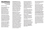
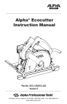
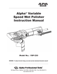
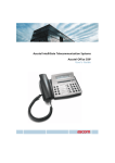
MANUAL Alpha® Wet Stone Cutter Instruction Manual Part No: AWS-125 / AWS-225 103 Bauer Drive, Oakland, NJ 07436 • 800-648-7229 • Fax: 800-286-0114 www.alpha-tools.com TABLE OF CONTENTS Introduction................................................................................................................. 3 About Symbols.................................................................................................... 3 Electrical Symbols.............................................................................................. 3 Safety instructions..................................................................................................... 4 For Safe Operation.............................................................................................. 4 AWS-125 Overview..................................................................................................... 6 Accessories................................................................................................................ 7 Additional Precautions for Using the Wet Stone Cutter......................................... 8 AWS-125 Wet Stone Cutter Operation...................................................................... 9 Main Connection................................................................................................. 9 Switching ON and OFF....................................................................................... 9 Ground Fault Circuit Interrupter...................................................................... 10 Before Use..................................................................................................................11 About Double Installation................................................................................ 12 Laws and Regulations of Noise Levels........................................................... 12 Instructions for Installing the Felt Strips........................................................ 12 Installation of Water Attachment..................................................................... 13 Water Flow......................................................................................................... 14 Adjusting Cutting Depth.......................................................................................... 14 Assembling and Disassembling............................................................................. 14 Straight Blade Installation....................................................................................... 15 Curve Blade Installation........................................................................................... 15 Free-Hand Cutting.................................................................................................... 16 Cutting Using Ruler Guide....................................................................................... 16 Cutting Using the Carriage Assembly and Guide Rail.......................................... 17 Curve Cutting Application....................................................................................... 18 Blade Inspection, Installation and Removal.......................................................... 19 AWS-125 Maintenance............................................................................................. 20 Replacing and Checking the Carbon Brushes...................................................... 21 Recommended Accessories.................................................................................... 24 Service and Warranty Information.......................................................................... 26 Loaner Program................................................................................................ 26 AWS-125 Wet Stone Cutter Schematic................................................................... 27 AWS-125 Wet Stone Cutter Parts List..................................................................... 28 EC Declaration of Conformity................................................................................. 30 Warranty.................................................................................................................... 30 Product Registration Card....................................................................................... 31 2 INTRODUCTION Thank you for purchasing the Alpha® AWS-125 Wet Stone Cutter. Please read this instruction manual thoroughly to ensure safe and correct use of the wet stone cutter. Keep this manual in a place where operators can access it easily whenever necessary. ABOUT THE SYMBOLS According to the hazard level, all safety notes in this manual are classified into “DANGER”, “WARNING”, and “CAUTION”. DANGER! Death or seriouspersonalinjuryisimminentwhen handling this tool incorrectly. WARNING! There is a possibility of death or serious personal injury when handling this tool incorrectly. CAUTION! There is a possibility of personal injury or property damage when handling this tool incorrectly. NOTE: In some situations, failing to observe WARNING notes could result in death or serious personal injury. Be sure to read and observe the safety notes to ensure safety and correct use of the wet stone cutter. ELECTRICAL SYMBOLS The following show the symbols used for tool. V Volts A Amperes Hz Hertz ~ or a.c. Alternating Current n0 No load speed …/min Revolution or reciprocation per minute kg Kilograms Protective Earth 3 Note: In some situations, failing to observe WARNING notes could result in orhdeat serious personal injury. Be sure to read and observe the safety notes to ensure safe and correct use of the wet stone cutter. CAUTION! The following are important notes for products, operation, and maintenance applicable to this stone cutter. SAFETY INSTRUCTIONS Read all these instructions before attempting to operate this product. WARNING! When using electric tools, basic safety precautions should always be followed to reduce the risk of fire, electric shock, and personal injury, including the following. For Safe Operation 1. 2. 3. 4. 5. 6. 7. 8. 9. 4 Keep work area clean Cluttered areas and benches invite injuries. Consider work area environment Do not expose power tools to rain. Do not use power tools in damp or wet locations without GFCI protection. Keep work areas well lit. Do not use the tool in presence of flammable liquids or gases. Guard against electric shock Prevent body contact with grounded surfaces. For example: pipes, radiators, ranges, and refrigerator enclosures; use grounded outlets. Keep children and visitors away Do not let visitors contact tool or extension cord. All visitors should be kept away from work area. Keep out of reach of children. Tool Storage When not in use, tools should be stored in a secure dry location. A locked storage area or high shelf out of children’s reach is ideal. Do not force the tool It will do the job better and be safer at the rate for which it was intended. Use the right tool Do not force a small tool or attachment to do the job of a heavy-duty tool. Do not use the tool for purposes it is not designed for – (for example – do not use stone cutter for cutting tree limbs or logs.) Dress properly Do not wear loose clothing or jewelry. Items such as these can be caught in moving parts. Rubber gloves and non-skid footwear are recommended when working outdoors. Wear protective hair covering to contain long hair. Use safety equipment Always wear safety glasses and if necessary, a face shield, dust mask and hearing protection. 10. Do not abuse the electrical cord Never carry the tool by the electrical cord or pull it to disconnect from receptacle. Keep the electrical cord away from heat, oil and sharp edges. 11. Secure workpiece Use clamps or a vise to hold workpiece rather than using your hands. 12. Do not overreach Keep proper footing and balance at all times. 13. Maintain tools with care Keep tools sharp and clean for better and safer performance. Follow instructions for lubricating and changing accessories. Inspect the electrical cord periodically and if damaged, have it repaired by authorized service facility. Inspect extension cords periodically and replace if damaged. Keep handles dry, clean and free from oil and grease. 14. Disconnect tools Disconnect the tool from the power supply when not in use, before servicing, and when changing accessories, such as blades, bits, cutters. 15. Remove adjusting keys and wrenches Check to see that keys and adjusting wrenches are removed from the tool before turning it on. 16. Avoid unintentional starting Do not carry a plugged-in tool with finger on switch. Be sure the switch is off when plugging in. 17. Outdoor use extension cords When tool is used outdoors, use only extension cords intended for use outdoors and so marked. 18. Stay alert Use caution and do not operate tool when you are tired or on medication. 19. Check for damaged parts Before using the tool each day, a guard or other part that is damaged should be carefully checked to determine that it will operate properly and perform its intended function. Check for alignment of moving parts, breakage of parts, mounting, and any other conditions that may affect its operation. A guard or other part that is damaged should be properly repaired or replaced by an authorized service center unless otherwise indicated elsewhere in this instruction manual. Have defective switches replaced by authorized service center. Do not use the tool if it cannot be turned on and off by the switch. 20.Warning The use of any other accessory or attachment other than recommended in this instruction manual or the catalog may present a risk of personal injury and could void the warranty. 21. Only qualified technicians should repair this tool This electric tool is manufactured in accordance with the standard safety rules. Only experts may carry out the repair of electric tools; otherwise, it may cause considerable danger for the operator. 5 AWS-125 OVERVIEW Power Switch Power Switch Lock Side Handle Water Valve Flange I and Flange II Water Nozzle TT Ruler Guide SPECIFICATIONS Height Adjustment Wing Screw Figure-1 Rating.................................................................................................110/220 Volts Amperage.................................................................................................... 11.2/5.5 Power............................................................................................................ 1200W No-load Speed.....................................................................................12,000 RPM Weight................................................................................................ 7.2 lbs/3.3kg Arbor...................................................................................................7/8” / 22.23m Cutting Disc Diameter.........................................................................5” / 125mm, Maximum Cutting Depth................................................................. 1-5/8” / 41mm 6 ACCESSORIES Figure-2 COMPONENTS: 1. 2. 3. 4. 5. 6. 7. 8. 9. Ground Fault Circuit Interrupter (Part No. 133289/133292) Water Valve (Part No. 133362) Water Attachment Assembly (Part No. 133287) Spanner Wrench M 22 (Part No. 133097) TT Ruler Guide (reversible) (Part No. 133266) T-Handle Wrench (Part No. 133098) Extra Carbon Brush (2 pc set) (Part No. 133033) Self-stick Felt Strip Set (Part No. 133369) Side Handle (Part No. 801086) 7 ADDITIONAL PRECAUTIONS FOR USING THE WET STONE CUTTER In addition to the general safety notes described on the preceding pages, please read and observe the following precautionary notes before using the wet stone cutter. DANGER! INSTRUCTIONS Alpha Professional Tools® provides the highest quality parts and manufacturing techniques in the manufacture of this tool. In order to obtain the maximum effectiveness and provide the highest degree of safety, it is necessary to review and follow these instructions carefully before using the tool. • • • • • • • • • • • • 8 SAFETY ADVICE Please note safety instructions on Page 3-5. Do not pierce the motor housing as this could damage the double insulation. Always remove plug from the outlet before making any changes to the settings or carrying out maintenance. Only plug-in when machine is switched off. Keep power cable clear from working range of the machine. The power cable should always lead away from you and behind the operating area. Before use, check the machine, cable and plug for any damages or material fatigue, only authorized service agents should carry out repairs. After switching off, the machine will not idle down immediately. Allow the machine to come to a complete stop before putting it down. Always wear safety glasses and ear protection when working with this machine. It is further recommended to wear safety gloves, apron, as well as sturdy non-slipping shoes. Only use saw blades whose permitted speed is at least as high as the highest no-load speed of the machine. Be sure saw blade fits tool properly and securely. Do not modify the tool to force fit the blade. For example do not remove blade guard. Check cutting tools before use. The saw blade must be properly mounted and turn freely. Perform a test run for at least 30 seconds without any load. Do not use damaged, out of round or vibrating cutting tools. Immediately switch off the machine in case of considerable vibrations or if other malfunctions occur. Check the machine in order to find out the cause. • • • • Always use and store the saw blades according to the manufacturer’s instructions. The flange bolt must be tightened before starting to work with the machine. The work piece must be secured if it is not heavy enough to prevent movement. Do not use emery wheel. The tool is designed for cutting on horizontal surfaces. USAGE This wet stone cutter can be used for cutting many different materials, e.g. tile, concrete, stone or glass. In case of doubt please read the manufacturer’s instruction. Do not use this product in any other way as stated for normal use. AWS-125 WET STONE CUTTER OPERATION MAIN CONNECTION Connect only to single-phase AC current supply and only to the main voltage specified on the rating plate. Connection to sockets without ground protection is possible as the appliance features protective insulation to DIN 57/740/ VDE 0740 and CEE 20. Radio suppression complies with the European standard EN 55014. SWITCHING ON AND OFF Intermittent use Switching on: Press switch trigger Switching off: Release switch trigger Continuous use: Switching on: Press the on/off switch and then the locking button; release on-off switch. Switching off: Press the on/off switch and then release. Locking Button Switch Trigger Figure-3 9 GROUND FAULT CIRCUIT INTERRUPTER: DANGER! Do not bypass the GFCI if this condition occurs, a real shock hazard may exist. WARNING! If the GFCI fails to trip when the test button is pressed, or fails to reset, the device is defective and should be replaced. If the GFCI tests properly without a load applied, but trips each time a load is connected, then the load (tool) has a ground fault condition and needs to be repaired or replaced. Do not bypass the GFCI if this condition occurs, a real shock hazard may exist. CAUTION! 1. The GFCI is a safety device, do not use as an off/on switch. 2. The GFCI on the tool will not protect you if you cut into another current carrying conductor. 3. Do not use where water may enter GFCI case. 4. Do not modify or allow GFCI to be immersed in water. A Ground Fault Circuit Interrupter (GFCI) is mounted at the end of power supply cord. The GFCI goes OFF when water enters inside the tool’s housing preventing the operator from receiving electric shocks. When the GFCI goes OFF, the Reset button pops up. This is the result of water entering the stone cutter housing. Reset Turn OFF the power switch and blow dry air inside the motor cover through the air vents. Red Run Light Test Press the GFCI Reset button. The stone cutter is ready to start working after the reset button is pressed down. 1. Do not remove the GFCI. Figure-4 10 2. Check items below when the GFCI goes OFF frequently. • Force applied on the stone cutter. • Water entered inside the stone cutter. • Voltage drop due to sharing the same power source in work area. • Worn carbon brushes BEFORE USE DANGER! Before using the machine, check the following items. In particular, check items 1 to 5 before plugging the power supply cord into the power outlet. 1. Check the working voltage. – Be sure the voltage specified on the nameplate is the voltage available at the power outlet. If the machine is used with higher voltage than specified, the motor will burnout. Any attempts to do so may damage the tool and/or cause an accident. 2. Make sure the ON/OFF switch is off. – If you plug in the power supply cord without realizing that the switch is ON, the machine will start and may cause an accident. – Make sure the switch is in the OFF position before plugging the cord in the power outlet. 3. Inspect the protective cover. – Do not remove the cover. It will protect you if the saw blade breaks. – Be sure to firmly attach the saw blade or any optional accessory. 4. Inspect the saw blade. – Check if you have a specified blade. – Never use cracked, chipped, or any damaged blades. – Follow the procedures specified in the instruction manual to properly attach applicable accessories. 5. Check the power outlet. – When the plug of the power supply cord is easily pulled out of the power outlet, the outlet should be replaced. For such tasks, consult an electrician. If the power outlet is used on a continuous basis, it may overheat and cause accidents. 6. Perform test runs. 11 WARNING! 1. Before turning the switch ON, make sure the rotating parts are not touching anything. If the switch is turned ON while they are in contact with anything else, the blade may get damaged and it may cause injuries. 2. When a new blade is attached and the switch is turned ON, keep your body well away from the exposed sides of the tool for a moment until the machine reaches its full speed. 3. It is very dangerous to perform cutting operations using cracked, chipped or damaged blades. Before starting cutting operations, keep the tool away from anyone nearby. Be sure to perform a few test runs to check whether there are any abnormalities. ABOUT DOUBLE INSULATION This machine is designed with double insulation. Two insulations are used between the conductor and the outer body of the machine. An Electric Machine with the double insulation highly improves safety from electric shocks. Do not attach or replace unspecified parts and do not assemble incorrectly. This may cause the insulation to malfunction. LAWS AND REGULATIONS OF NOISE LEVELS Please observe local laws and regulations regarding noise level in order to avoid disturbing surrounding areas. Install a soundproof wall if required to comply with the local laws and regulations. INSTRUCTIONS FOR INSTALLING THE FELT STRIPS ON THE AWS-125/AWS-225 BASE PLATE: 1. Wipe base plate with a clean rag to remove any dirt or residue. 2. Peel off film from the pressure sensitive adhesive on the enclosed felt strips. 3. Place strips on base plate parallel with the blade and press into place. Figure-5 12 INSTALLATION OF WATER ATTACHMENT 1. Remove the wing screw and washer for adjusting the cutting depth. (See Figure-6) 2. Raise cutting depth so there is room between the body and the base plate. (See Figure-6) Figure-6 3. Insert the plastic nozzle on the water-feed assembly behind the height adjustment slide. Make sure that the water valve bracket (Part No. 133094) is in front of the slide. If your blade is already installed, the plastic nozzles should be positioned so that each nozzle directs water spray onto each side of the blade. (See Figure-7 & Figure-8) Figure-7 Figure-8 4. Align the water valve bracket with the wing nut hole and insert wing bolt. (See Figure-9) Figure-9 5. Adjust the height of the blade and securely tighten the wing bolt. 13 WATER FLOW Connect only to an isolating transformer when using water flow. Connect the nylon hose onto the water valve, then connect the adapter on the nylon hose to the water faucet. Simply adjust the volume of the water flow by turning the handle on the water valve. Figure-10 ADJUSTING CUTTING DEPTH 1. Loosen the wing screw on the depth indicator and move the base plate up or down to the desired cutting depth. Re-tighten the wing screw to a hand tight condition as shown in Figure 11 and Figure 12. Figure-12 Figure-11 Wing Screw Spanner Wrench ASSEMBLING & DISASSEMBLING Make certain to switch off the machine and unplug from outlet before assembling or disassembling of the saw blade. Clamp the flange with spanner wrench and loosen bolt by turning the T-handle clockwise to loosen. Disassemble bolt, flange and saw blade. Figure-13 T-handle Wrench...turn clockwise to loosen Please follow the same but reverse procedures when reassembling the saw blade. Be sure the direction shown by arrow on the surface of the saw blade is the same as that shown on the cap of the machine. Make certain the bolt is firmly tightened. 14 Figure-14 STRAIGHT BLADE INSTALLATION Flange I Part No. 133418 ® Alpha Straight Cutting Blade Flange II Part No. 133419 Figure-15 Bolt M6x20 Left Part No. 133464 CURVE CUTTING BLADE INSTALLATION Flange I Part No. 133418 Flange III Part No. 133432 Flange II Part No. 133419 Alpha® Contour Curve Cutting Blade Figure-16 Bolt M6x30 Left Part No. 133463 15 CAUTION! Allow the saw blade to do the work, applying excessive forward pressure to the tool will slow down the RPM’s and burn up the motor, which voids the limited warranty of the tool. This tools should only be used for cutting on a horizontal surface. Be sure to follow daily maintenance before and after each use. OPTION 1: FREE-HAND CUTTING If you are cutting stone or tile less than 20 mm (3/4”) thick, the cut can be done in one pass (allow saw blade to do the work). 2. If you are cutting stone or tile more than 20mm thick you will need to make the cut in two passes. Adjust the height to 15-20mm for the first pass, then adjust the saw blade below the stone for the second pass ( allow the saw blade to do the work). 3. Adjust the amount of water-flow to cool the blade and remove the waste, excessive water flow will get inside the tool and trip the GFCI. 4. Set the base plate on the workpiece and align to the cutting mark on the base plate to cut line on stone. 5. Press the on/off switch to start the motor and allow the tool to attain full speed before starting to cut. 6. Advance the tool slowly allowing the blade to do the work, keeping the base plate flat on the stone and the cut mark in line with your cut line. 7. Slow the cutting speed for the last 1/2” to prevent the tile or stone from chipping. OPTION 2: USING THE RULER GUIDE Install the ruler on the AWS-125 by inserting the arms into the appropriate slots on the base plate and tightening the screws to secure the ruler in place. When using the edge of the stone as your guide, install the ruler so that it is below the base plate (Figure-17). Measure the distance from the edge to the intended cut and use this measurement to set the ruler at the proper distance. When using a straight edge as a guide, install the ruler so that it is above the base plate (Figure-18). Measure the distance from the straight edge to the intended cut and use it to set the ruler at the proper distance. When cutting, simply keep the ruler in contact with the straight edge while maintaining even cutting pressure and your cuts will b e Figure-17 16 Figure-18 straight. OPTION 3: USING THE CARRIAGE ASSEMBLY AND GUIDE RAIL Install the guide rail 2-3/4 inches / 70mm from the intended cut. Take care to ensure that the guide rail is properly clamped in place and double check your measurements. Attach the carriage assembly to the base plate by aligning the base plate properly and attaching the pressing plates. Make sure that the pressing plates are securely fastened. The AWS should be immobile with in the carriage assembly. Slide the carriage onto the guide rail and proceed to cut. Maintain even cutting pressure. When finished, the rail is in position to polish the straight edge with the Alpha® Edgecrafter. Adjusting cutting depth: Loosen the wing bolt on the depth indicator and move the base floor up and down to the desired cutting depth and tighten the wing nut to fix the base floor. Remember to tighten the wing bolt after you finish the adjustment of the cutting depth each time. Carriage Assembly Guide Rail Figure-20 17 CURVE CUTTING APPLICATION When cutting the curved line, you can remove the ruler guide and cut free-hand. (Figure-8) Step 1. Score along the cutting line (1/3 width of stone). Step 2. Step-cut along scored line (2/3 width of stone). Step 3. Plunge cut all the way to make full contact between bottom plate and stone, then maintain even cutting pressure to follow curved cut line. WARNING! Support the sink cutout area; sinkhole cutout piece may drop to the floor at the end of cutting application, if not supported. 1. Support the sink cutout area prior to cutting, otherwise the work piece may drop to the floor at the end of the cutting application. 2. Use the Alpha® Contour Cutting blade only. Application with inferior blades may cause damage to the stone cutter. 3. Do not force the stone cutter during the cutting application. Allow the blade to cut at its own pace. Excessive force may damage the stone cutter. Step 1 Step 2 Figure-21 18 Step 3 BLADE INSPECTION, INSTALLATION, AND REMOVAL DANGER! Be sure to unplug the power cord from the outlet before attaching or removing the saw blade from the tool. Accidental starting of the motor may cause bodily injury. WARNING! Be sure to securely tighten the flange assembly and all loose screws before testing the unit. Please allow the saw blade to do the work. Applying excessive force may damage the saw blade and cause premature failure of the bearings and gears. Such action may decrease the rotation speed of the motor which reduces the efficiency of the dust suction because its power is driven by the spindle Only use saw blades with 20mm arbors and maximum speed rating equal to or higher than the name plate of RPM of tool. 1. To remove the flange bolt from the spindle hold Flange II in position with the 22 mm spanner wrench (133097) while turning the flange bold with the T-handle wrench (133098) in a clockwise rotation until it is removed. 2. With the flange bolt removed, remove Flange II off of Flange I. 3. Install your 20mm arbor saw blade onto Flange I with the arrow on the blade pointing in the same direction as the arrow on the cover (blade will turn in a clockwise rotation), the cutting wheel should fit tightly on the Flange I. 4. Reinstall Flange II and then the flange bolt, turning counter-clockwise to install, once flange bolt is hand tight use the 22mm spanner wrench to hold Flange II in place and finish tightening the flange bolt with the T-handle wrench. 19 AWS-125 MAINTENANCE DAILY 1. Before daily start-up inspect tool, power cord, GFCI, and Saw Blade, looking for chips and cracks. 2. If damage has occurred, repair affected areas before use. 3. Connect the tool to the correct power source and test the Ground Fault Circuit Interrupter (GFCI) before using the tool. Push the red RESET button and confirm that the red run light is on. Push the yellow TEST button and confirm that the red run light is off, push the red RESET button to use the tool. 4. After daily use of the tool, clean and blow off the exterior of tool and around air intake vents to remove any standing water or stone dust on the field coil, carbon brushes, and bearings. Failure to do this will shorten the life of your tool, and could void your warranty. PERIODIC Preventive maintenance performed by unauthorized personnel may result in misplacing of internal wires and/or components which voids the warranty and could cause serious hazards. We recommend that tool service and repairs not covered in the manual be performed by an Alpha® Repair Center. Periodic maintenance is done to check the tool and to minimize down time. These checks are done based on hours of operation and operating conditions. Operating condition can vary depending on the work surface and job being performed. If the tool is not used for a long period of time the carbon brushes should be checked and the commutator cleaned, before putting the tool back into operation. BEARINGS AND GEARS To minimize your tool’s downtime and expensive repairs, it is recommended to send the tool back to an Alpha® Repair Center after about 300 to 400 hours of operation, or every second carbon brush change. The bearings should be replaced and the gears should be checked. If your tool starts to sound different, this could be an indication of a worn bearing. Continuing to use to use the tool in this condition could result in overheating or motor failure. 20 REPLACING AND CHECKING THE CARBON BRUSHES In order to keep your tool running correctly, you need to check your carbon brushes after every one hundred hours (100 hrs) of use. Carbon brushes wear out over time based on tool’s usage. If a carbon brush is worn out, it may cause the motor to malfunction or fail to run. The carbon brushes should be replaced when they are worn down to a quarter of an inch (1/4”) in size. DANGER! Be sure to unplug the power cord from the outlet before assembling or disassembling the tool. Accidental starting of the motor may cause bodily injury. CARBON BRUSH REPLACEMENT 1. Locate the Carbon Brush Caps at the rear of the motor (one on each side) as shown in Figure 22. Carbon Brush Cap Figure-22 2. Unscrew cap completely until carbon brush assembly releases from brush holder as shown in Figure 23. Figure-23 21 3. Check the carbon brush for wear. Replace if worn down to a 1/4" or if spring is damaged. New Carbon Brush Old Carbon Brush worn down to a quarter of an inch (1/4”). Figure-24 4. Install new carbon brush with the proper alignment of the brush holder followed by the cap as shown in Figure 25. Proper Alignment Figure-25 22 Note: If you notice any resistance while tightening the carbon brush cap, it is an indication that the top plate on the carbon brush assembly is sticking inside the brush cap. Continuing to tighten will damage the carbon brush spring. (Go to step 6 to correct this problem) 5. Tighten cap until secure as shown in Figure 26. Figure-26 6. Remove the cap and carbon brush from the tool, visually check the two parts for defects as shown in Figure 27. Figure-27 Carbon Brush Cap Top Plate 23 7. Check to see if the two parts move freely by pushing the top plate of the carbon brush into the recess on the bottom of the carbon brush cap and rotate. Top Plate Carbon Brush and Cap Figure-28 8. If the two parts stick together, replace the carbon brush cap and repeat step 7. 9. If the top plate of the carbon brush sticks in the new cap, you need to replace the carbon brush and repeat step 7. 10. Keep trying until carbon brush top plate can move freely inside of the recess on the bottom of carbon brush cap. 11. When the correct match is found, install in the tool. RECOMMENDED ACCESSORIES Alpha ® Plus The ultimate diamond blade for cutting granite, marble, natural and engineered stone, ceramic tile and other hard materials. Made with the highest quality diamonds and matrix for long life and chipfree cutting. The high performance turbo rim helps get the job done fast!. 24 Alpha ® Eclipse II The ideal general purpose blade for use on masonry, concrete and tile. The turbo rim allows for safe and smooth operation. It is cost effective, long lasting and provides consistent results. A valuable addition to your toolbox. Alpha ® Libero The ultimate blade for cutting marble: The advanced diamond rim is designed to cut softer materials (marble, travertine, soapstone and alabaster) without the chipping and cracking commonly associated with dry cutting. It is aggressive and easy to use, which reduces finishing time and saves on raw materials. Alpha ® Numero Uno Our premium wet saw blade: It is designed for cutting natural and engineered stone slabs and tile. The advanced style rim will cut most difficult natural and engineered stone tiles quickly and efficiently while reducing the risk of chipping and breaking. Alpha ® Numero Uno is the number one choice. Alpha ® PORCELLANA The Alpha ® Porcellana provides fast and consistent performance with minimal chipping when cutting porcelain tile or slab. Designed for continuous cutting; no dressing necessary. Alpha® Porcellana is the best choice for cutting porcelain. Also works well on glass and natural or engineered stone. Alpha ® CONTOUR BLADE FOR GRANITE The new and improved Alpha ® Contour Blades are specifically designedforcuttingsinkholesandothercurvecuttingapplications on granite and harder types of natural and engineered stone. Alpha’s new design incorporates diamonds on both sides of the steel core for better performance. In combination with Alpha® AWS-125 Wet Stone Cutter makes application easy for everyone. 25 Alpha ® CONTOUR BLADE FOR PORCELAIN This is the latest addition to Alpha® Contour curve cutting series blade for Porcelain. Alpha® made this application possible in conjunction with Alpha® AWS-125 Wet Stone Cutter. You can cut sinkhole of 1-1/4” porcelain slab without breaking the rim. Due to the nature of the material, this blade must be used wet only. *Always wear eye protection and proper personal safety equipment when using these products. Alpha ® VACUUM HOLD DOWN SYSTEM TheAlpha® Vacuum Hold Down System is a clampfree restraining system utilizing compressed air that is particularly useful when performing sink cutouts, polishing with the Alpha® Edgecrafter, profiling with a router, and other applications where clamping is necessary. SERVICES AND WARRANTY INFORMATION LOANER PROGRAM: Loaner tools can be issued to temporarily replace a tool that is being returned to Alpha® for repair. If more than one tool is being returned for repair, the number of loaner tools provided will be based on availability. If a loaner tool is required, contact the Tool Department at Alpha® at (800) 648-7229 to receive a Loaner Tool Application. A valid credit card number must be provided as a security deposit. The credit card will only be charged if the loaner tool is not returned to Alpha® within 30 days. An authorized signature is required for the credit card being used. A second signature is required as an agreement of the overall policy. Note: This program is not available outside the continental United States. NEED MORE INFORMATION For information on Alpha Professional Tools® complete product line, visit us on the web at www.alpha-tools.com 26 ALPHA® AWS-125 WET STONE CUTTER SCHEMATIC 27 ALPHA® AWS-125 WET STONE CUTTER PARTS LIST 28 DRAWING NO. PART NO. DESCRIPTION QUANTITY 1 133080 Screw M5×40 3 2 130031 Self-tapping Screw St 3.9 X19 7 3 133289/133292 GFCI 110V/220V 1 4 133033 Carbon Brush (2 pc set) 2 5 133031 Brush Holder 2 6 133032 Brush Cap 2 7 133422 Rated Plate 110V 1 8 133047 Cable Sleeve 1 9 130618 Block Terminal 2 10 133040 Wire Terminal 2 11 133042 Insulation Pipe 2 12 133034 Brush Terminal Assembly 2 13 133436/133004 Field Coil 110V/220V 1 14 133086 Cable Clamp 1 16 133030 Air Bridge 1 17 133025 Bearing 608-2RZ 1 18 133024 Insulation Disc 1 19 133439/133012 Armature 110V/220V 1 20 133026 Bearing Cover 1 21 133027 Ball Bearing 629-2RZ 1 22 133048 Gear (Small) 1 23 133051 Snap Ring M8 1 24 133050 Woodruff Key 1 25 133028 Bearing Sleeve 1 26 133029 Self-tapping Screw ST 4.8×65 2 27 133392 Condensor Assembly 1 28 133254 Handle (for AWS-125) 1 29 133043 Switch (With Screw) 1 30 133044 Rubber Switch Cover 1 31 133041 Cable Clip 2 32 133003 Rear Motor Housing (Blue) 1 33 133429 Spindle Assembly (for AWS-125) 1 34 133413 Cover 1 35 133079 Screw M4×25 4 36 133060 Screw Cap 1 37 133419 Flange II (for AWS-125) 1 38 133464 Screw M6x20 - left 1 ALPHA® AWS-125 WET STONE CUTTER PARTS LIST DRAWING NO. PART NO. 39 133418 Flange I (for AWS-125) 1 40 133062 O Ring 18×2.5 1 41 133057 Spindle (for AWS-125) 1 42 133053 Ball Bearing 6201-2RS 1 43 133242 Brand Label 1 44 133416 TT Ruler Guide (for AWS-125) 1 45 133058 Gear (Big) 1 46 133066 Needle Bearing Bk 0810 1 47 133255 Gear Box 1 48 133067 O Ring 25.5×2 1 49 133084 Wing Screw 3 50 133269 Washer For Ruler 2 51 133085 Pin 6x28 1 52 133107 Screw M3x5 1 53 133108 Lock Washer M3 1 54 133094 Water Valve Bracket (for AWS-110/125) 1 55 133414 Base Plate Assembly 1 56 133420 Nozzle (for AWS-125) 1 57 133362 Water Valve (for AWS-110/125) 1 59 133229 Water Hose 8mm ODx10ft (3m) 1 60 133231 Compression Nut 1 61 133230 Sleeving Connector 1 63 133232 Water Hose Adapter 1 64 133233 Hose Washer (Rubber) 1 65 133291/133237 Cable 110V/220V 1 66 801086 Side Handle (for AWS-125/ECC-125) 1 67 133369 Felt Strip Set 2 68 133432 Flange III (for AWS-125) 1 69 133463 Screw M6x30 - left 1 70 133097 Spanner Wrench M 22 1 71 133098 T-Handle Wrench 1 73 133071 Flat Washer M6 1 74 133072 Spring Washer M6 1 75 133234 Adapter Fitting 1 76 133236 Compression Washer 1 133441 BMC (Blow Mold Case) for AWS-125 1 (not shown) DESCRIPTION QUANTITY 29 EC DECLARATION OF CONFORMITY Name of Manufacturer: Alpha Professional Tools ® Address of Manufacturer: 103 Bauer Drive Oakland, NJ 07436 USA Herewith declares that: ELECTRIC HAND TOOL: “Electric Stone Cutter” Make: Alpha Professional Tools ® Type: AWS-225 -Does comply with the provisions of EMC 2004/108/EC, the Low Voltage Directive 2006/95/EC and Machinery Directive 2006/42/EC . And furthermore declares that: -The following (parts/clauses of) harmonized standards have been applied: EN61000-3-3/+A2:2005,EN55014-1:2006,EN55014-2/A1:2001,EN61003-311:2006,EN60745-1:2009. Year of affix CE Marking: 2012 Oakland, New Jersey USA Jan / 11 .2012 Nao Takahashi (President) Assembled in China 30 PRODUCT REGISTRATION CARD Model No. Serial No. Company Name: ______________________________________________ Name: ______________________________________________________ Address: ____________________________________________________ City: _______________________State: ________Zip: ________________ Telephone: ___________________________________________________ Purchase Date: _______________________________________________ Dealer’s Name: _________________________________ Note: Serial & Model Number must be included for proper registration. (800) 648-7229 Register online at: www.alpha-tools.com/productregistration.aspx Mail or Fax to: Alpha Professional Tools® 103 Bauer Drive, Oakland, NJ 07436 Fax: 800-286-0114 31 103 Bauer Drive, Oakland, NJ 07436 • 800-648-7229 • Fax: 800-286-0114 www.alpha-tools.com Copyright © 2008 Alpha Professional Tools. All rights reserved. 2/27/2013