1
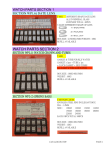
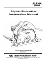
MANUAL Alpha® Ecocutter Instruction Manual Part No: ECC-125/ECC-225 Version 5 103 Bauer Drive, Oakland, NJ 07436 • 800-648-7229 • Fax: 800-286-0114 www.alpha-tools.com TABLE OF CONTENTS Introduction................................................................................................................3 About The Symbols..............................................................................................3 Safety Instructions ..............................................................................................3 For Safe Operation................................................................................................3 Ecocutter Overview...................................................................................................6 Specifications.......................................................................................................6 Accessories...........................................................................................................7 Ecocutter Operation..................................................................................................8 Main Connection...................................................................................................8 Switching On and Off............................................................................................8 Circuit Breaker......................................................................................................8 Before Use..................................................................................................................9 About Double Insulation.....................................................................................10 Laws and Regulations of Noise Levels............................................................10 Adjusting The Cutting Depth..................................................................................11 Ruler Guide Usage Option......................................................................................11 Option A - Guide Below The Base Plate............................................................12 Option B - Guide Above The Base Plate...........................................................12 Ecocutter Dust Hose and Bag Installation............................................................13 Blade Inspection, Installation, and Removal........................................................15 Ecocutter Maintenance...........................................................................................18 Daily......................................................................................................................18 Periodic................................................................................................................18 Bearings and Gears............................................................................................18 Replacing and Checking the Carbon Brushes.....................................................19 Carbon Brush Replacement...............................................................................19 Belt Removal and Replacement.............................................................................22 Testing the Unit For Flow...................................................................................23 Inner Belt Removal..............................................................................................24 Inspecting and Cleaning The Belts And Pulleys..............................................25 Inner Belt Installation..........................................................................................26 Outer Belt Removal ............................................................................................27 Outer Belt Installation.........................................................................................28 Ecocutter Schematic (ECC-125).............................................................................29 Ecocutter Parts List (ECC-125)..............................................................................30 Services and Warranty Information.......................................................................33 Loaner Program..................................................................................................33 Need More Information ......................................................................................33 Warranty...............................................................................................................33 EC Declaration Of Conformity................................................................................34 Product Registration Card......................................................................................35 2 INTRODUCTION Thank you for purchasing the Alpha® Ecocutter Dry Tile Cutting System. Please read this instruction manual thoroughly to ensure safe and correct use of the Ecocutter Dry Tile Cutting System. Keep this manual in a place where operators can access it easily whenever necessary. ABOUT THE SYMBOLS According to the hazard level, all safety notes in this manual are classified into “DANGER”, “WARNING”, and “CAUTION”. DANGER! Death or serious personal injury is imminent when handling this stone cutter incorrectly. WARNING! There is a possibility of death or serious personal injury when handling this stone cutter incorrectly. CAUTION! There is a possibility of personal injury or property damage when handling this stone cutter incorrectly. Note: In some situations, failing to observe WARNING notes could result in orhdeat serious personal injury. Be sure to read and observe the safety notes to ensure safe and correct use of the stone cutter. CAUTION! The following are important notes for products, operation, and maintenance applicable to this stone cutter. SAFETY INSTRUCTIONS Read all these instructions before attempting to operate this product. WARNING! When using electric tools, basic safety precautions should always be followed to reduce the risk of fire, electric shock, and personal injury, including the following. For Safe Operation 1. Keep work area clean Cluttered areas and benches invite injuries. 3 2. Consider work area environment Do not expose power tools to rain. Do not use power tools in damp or wet locations without GFCI protection. Keep work areas well lit. Do not use the tool in presence of flammable liquids or gases. 3. Guard against electric shock Prevent body contact with grounded surfaces. For example: pipes, radiators, ranges, and refrigerator enclosures; use grounded outlets. 4. Keep children and visitors away Do not let visitors contact tool or extension cord. All visitors should be kept away from work area. Keep out of reach of children. 5. Tool Storage When not in use, tools should be stored in a secure dry location. A locked storage area or high shelf out of children’s reach is ideal. 6. Do not force the tool It will do the job better and be safer at the rate for which it was intended. 7. Use the right tool Do not force a small tool or attachment to do the job of a heavy-duty tool. Do not use the tool for purposes it is not designed for – (for example – do not use stone cutter for cutting tree limbs or logs.) 8. Dress properly Do not wear loose clothing or jewelry. Items such as these can be caught in moving parts. Rubber gloves and non-skid footwear are recommended when working outdoors. Wear protective hair covering to contain long hair. 9. Use safety equipment Always wear safety glasses and if necessary, a face shield, dust mask and hearing protection. 10. Do not abuse the electrical cord Never carry the tool by the electrical cord or pull it to disconnect from receptacle. Keep the electrical cord away from heat, oil and sharp edges. 11. Secure workpiece Use clamps or a vise to hold workpiece rather than using your hands. 12. Do not overreach Keep proper footing and balance at all times. 13. Maintain tools with care Keep tools sharp and clean for better and safer performance. Follow instructions for lubricating and changing accessories. Inspect the electrical cord periodically and if damaged, have it repaired by authorized service facility. Inspect extension cords periodically and replace if damaged. Keep handles dry, clean and free from oil and grease. 14. Disconnect tools Disconnect the tool from the power supply when not in use, before servicing, and when changing accessories, such as blades, bits, cutters. 4 15. Remove adjusting keys and wrenches Check to see that keys and adjusting wrenches are removed from the tool before turning it on. 16. Avoid unintentional starting Do not carry a plugged-in tool with finger on switch. Be sure the switch is off when plugging in. 17. Outdoor use extension cords When tool is used outdoors, use only extension cords intended for use outdoors and so marked. 18. Stay alert Use caution and do not operate tool when you are tired or on medication. 19. Check for damaged parts Before using the tool each day, a guard or other part that is damaged should be carefully checked to determine that it will operate properly and perform its intended function. Check for alignment of moving parts, breakage of parts, mounting, and any other conditions that may affect its operation. A guard or other part that is damaged should be properly repaired or replaced by an authorized service center unless otherwise indicated elsewhere in this instruction manual. Have defective switches replaced by authorized service center. Do not use the tool if it cannot be turned on and off by the switch. 20.Warning The use of any other accessory or attachment other than recommended in this instruction manual or the catalog may present a risk of personal injury and could void the warranty. 21. Only qualified technicians should repair this tool This electric tool is manufactured in accordance with the standard safety rules. Only experts may carry out the repair of electric tools; otherwise, it may cause considerable danger for the operator. 5 ECOCUTTER OVERVIEW Power Switch Lock Power Switch Fan Side Cover Breaker TT Ruler Guide Flange Assembly SPECIFICATIONS Side Handle Rating........................................................................................ 110/220 Volts Amperage............................................................................................11.2/5.5 Power.................................................................................................... 1200W No-load Speed (min-1)................................................................ 12,000 RPM Weight...................................................................................... 9.5 lbs / 4.3 kg Arbor.......................................................................................... 7/8” / 22.3mm Cutting Disc Diameter.................................................................. 5” / 125mm Max. Cutting Depth................................................................... 1-1/8” / 29mm (without Ecocutter Table) 6 Figure-1 ACCESSORIES Figure-2 COMPONENTS: 1. Dust Hose (Part No. 133533) 2. Dust Gate w / Anti-back Flow Flap (Part Nos. 133531 / 133530) 3. Side Handle (Part No. 801086) 4. Hexagon Ring Spanner (Part No. 133534) 5.Wrench (Part No. 133535) 6. Dust Bag (Part No. 133544) 7. TT Ruler Guide (Part No. 133527) 8. Hook and Loop Strap (2 pcs) (Part No. 133551) 7 ECOCUTTER OPERATION MAIN CONNECTION Connect Ecocutter to a single phase AC current supply and to the main voltage specified on the cutter’s rating plate. SWITCHING ON AND OFF Intermittent use: Switching on: Press switch trigger Switching off: Release switch trigger Continuous use: Switching on: Press the switch trigger and then the locking button; release on/off switch Switching off: Press the switch trigger and then release Locking Button Switch Trigger Figure-3 CIRCUIT BREAKER CAUTION! If the tool stops during operation you need to switch the unit off before resetting the circuit breaker. Resetting the circuit breaker with the trigger lock on can cause an accident. Note: If the circuit breaker stops the tool repeatedly, this could be an indication that excessive pressure is being applied to the tool, slowing the motor and causing it to overheat. Use less force and allow the tool to do the work. The circuit breaker can also trip, if the carbon brushes are completely worn and need to be replaced. 8 The Ecocutter is supplied with an in-line circuit breaker. In the event that the breaker is tripped, push the button to reset. Once you are able to reset the circuit breaker, run the tool in a no load condition allowing air to pass over the motor and cool it down. Reset Button In-line Circuit Breaker Figure-4 BEFORE USE DANGER! Before using the machine, check the following items. In particular, check items 1 to 5 before plugging the power supply cord into the power outlet. 1. Check the working voltage. – Be sure the voltage specified on the nameplate is the voltage available at the power outlet. If the machine is used with higher voltage than specified, the motor will burnout. Any attempts to do so may damage the tool and/or cause an accident. 2. Make sure the ON/OFF switch is off. – If you plug in the power supply cord without realizing that the switch is ON, the machine will start and may cause an accident. – Make sure the switch is in the OFF position before plugging the cord in the power outlet. 3. Inspect the protective side cover. – Do not remove the side cover. It will protect you if the saw blade breaks. – Be sure to firmly attach the saw blade or any optional accessory. 9 4. Inspect the saw blade. – Check if you have a specified blade. – Never use cracked, chipped, or any damaged blades. – Follow the procedures specified in the instruction manual to properly attach applicable accessories. 5. Check the power outlet. – When the plug of the power supply cord is easily pulled out of the power outlet, the outlet should be replaced. For such tasks, consult an electrician. If the power outlet is used on a continuous basis, it may overheat and cause accidents. 6. Perform test runs. WARNING! 1. Before turning the switch ON, make sure the rotating parts are not touching anything. If the switch is turned ON while they are in contact with anything else, the blade may get damaged and it may cause injuries. 2. When a new blade is attached and the switch is turned ON, keep your body well away from the exposed sides of the tool for a moment until the machine reaches its full speed. 3. It is very dangerous to perform cutting operations using cracked, chipped or damaged blades. Before starting cutting operations, keep the tool away from anyone nearby. Be sure to perform a few test runs to check whether there are any abnormalities. ABOUT DOUBLE INSULATION This machine is designed with double insulation. Two insulations are used between the conductor and the outer body of the machine. An Electric Machine with the double insulation highly improves safety from electric shocks. Do not attach or replace unspecified parts and do not assemble incorrectly. This may cause the insulation to malfunction. LAWS AND REGULATIONS OF NOISE LEVELS Please observe local laws and regulations regarding noise level in order to avoid disturbing surrounding areas. Install a soundproof wall if required to comply with the local laws and regulations. 10 ADJUSTING THE CUTTING DEPTH 1. Loosen the wing screw on the depth indicator and move the base plate up or down to the desired cutting depth. Re-tighten the wing screw to a hand tight condition as shown in Figure 5 and Figure 6. Figure-5 Wing Screw Figure-6 RULER GUIDE USAGE OPTION According to the application, there are two options for using the ruler guide. 1. Install the ruler on the Ecocutter by inserting the arms into the appropriate slots on the base plate and tightening the screws to secure the ruler in place as shown in Figure 7 and Figure 8. Indented Cut Figure-8 Figure-7 11 2. When cutting, simply keep the ruler in contact with edge of stone or the straight edge while maintaining even cutting pressure to ensure the cuts will be straight. OPTION A - GUIDE BELOW THE BASE PLATE When using the edge of the stone as your guide, install the ruler guide downward so that the ruler guide would be below the base plate and the inner side of the ruler guide would follow the edge of the stone. Measure the distance from the edge to the indented cut and use this measurement to set the ruler at the proper distance. (See Figure 9) Figure-9 OPTION B - GUIDE ABOVE THE BASE PLATE When using the straight edge as a guide, install the ruler guide upward so that the ruler guide would be above the base plate and the outer edge of the ruler guide would follow the edge of the straight edge. Measure the distance from the straight edge to the intended cut and use it to set the ruler at the proper distance. (See Figure 10) Figure-10 12 ECOCUTTER DUST HOSE AND BAG INSTALLATION 1. Install back flow preventer assembly to the Ecocutter exhaust port with the dust gate in the upright position as shown in Figure 11. Dust Gate Figure-11 2. Slide the dust hose onto the dust gate assembly as shown in Figure 12. Figure-12 Dust Hose 3. Check for a tight connection as shown in Figure 13. Figure-13 13 4. Slip dust bag over hose end as shown in Figure 14. Figure-14 Dust Bag 5. Secure with hook and loop strap as shown in Figure 15. Figure-15 6. See Figure 16 for completed dust bag installation. Figure-16 14 BLADE INSPECTION, INSTALLATION, AND REMOVAL DANGER! Be sure to unplug the power cord from the outlet before attaching or removing the saw blade from the tool. Accidental starting of the motor may cause bodily injury. WARNING! Be sure to securely tighten the flange assembly and all loose screws before testing the unit. Please allow the saw blade to do the work. Applying excessive force may damage the saw blade and cause premature failure of the bearings and gears. Such action may decrease the rotation speed of the motor which reduces the efficiency of the dust suction because its power is driven by the spindle 1. Remove flange bolt (left-hand thread) as shown in Figure 17. Flange Bolt Outer Flange Figure-17 2. Remove outer flange as shown in Figure 18. Figure-18 15 3. Set the rotation direction of the blade so that it matches the Ecocutter rotation arrow located on the guard as shown in Figure 19. Rotation Direction on Guard Rotation Direction on Blade Figure-19 4. Slide the blade between the inner flange and guard as shown in Figure 20. Figure-20 16 5. Install outer flange and flange bolt as shown in Figure 21. Figure-21 6. Tighten bolt with the supplied wrenches to a secure condition as shown in Figure 22. , Figure-22 17 ECOCUTTER MAINTENANCE DAILY 1. Before daily start-up inspect tool, power cord, circuit breaker assembly, and saw blade looking for chips and cracks. Inspect the dust bag for holes or if it is full and needs to be replaced. 2. If damage has occurred, repair affected areas before use. 3. Turn the unit on to ensure that the fan is running and the dust bag is inflating, a new bag will not inflate until the pores in the material start to fill with stone dust. 4. After daily use of the tool, clean and blow off the exterior of tool and around air intake vents on rear of motor housing. PERIODIC Preventive maintenance performed by unauthorized personnel may result in misplacing of internal wires and/or components which voids the warranty and could cause serious hazards. We recommend that tool service and repairs not covered in the manual be performed by an Alpha® Repair Center. Periodic maintenance is done to check the tool and to minimize down time. These checks are done based on hours of operation and operating conditions. Operating condition can vary depending on the work surface and job being performed. If the tool is not used for a long period of time the carbon brushes should be checked and the commutator cleaned, before putting the tool back into operation. BEARINGS AND GEARS To minimize your tool’s downtime and expensive repairs, it is recommended to send the tool back to an Alpha® Repair Center after about 300 to 400 hours of operation, or every second carbon brush change. The bearings should be replaced and the gears should be checked. If your tool starts to sound different, this could be an indication of a worn bearing. Continuing to use to use the tool in this condition could result in overheating or motor failure. 18 REPLACING AND CHECKING THE CARBON BRUSHES In order to keep your tool running correctly, you need to check your carbon brushes after every one hundred hours (100 hrs) of use. Carbon brushes wear out over time based on tool’s usage. If a carbon brush is worn out, it may cause the motor to malfunction or fail to run. The carbon brushes should be replaced when they are worn down to a quarter of an inch (1/4”) in size. DANGER! Be sure to unplug the power cord from the outlet before assembling or disassembling the tool. Accidental starting of the motor may cause bodily injury. CARBON BRUSH REPLACEMENT 1. Locate the Carbon Brush Caps at the rear of the motor (one on each side) as shown in Figure 23. Carbon Brush Cap Figure-23 2. Unscrew cap completely until carbon brush assembly releases from brush holder as shown in Figure 24. Figure-24 19 3. Check the carbon brush for wear. Replace if worn down to a 1/4" or if spring is damaged. New Carbon Brush Old Carbon Brush worn down to a quarter of an inch (1/4”). Figure-25 4. Install new carbon brush with the proper alignment of the brush holder followed by the cap as shown in Figure 26. Proper Alignment Figure-26 20 Note: If you notice any resistance while tightening the carbon brush cap, it is an indication that the top plate on the carbon brush assembly is sticking inside the brush cap. Continuing to tighten will damage the carbon brush spring. (Go to step 6 to correct this problem) 5. Tighten cap until secure as shown in Figure 27. Figure-27 6. Remove the cap and carbon brush from the tool, visually check the two parts for defects as shown in Figure 28. Figure-28 Carbon Brush Cap Top Plate 21 7. Check to see if the two parts move freely by pushing the top plate of the carbon brush into the recess on the bottom of the carbon brush cap and rotate. Top Plate Carbon Brush and Cap Figure-29 8. If the two parts stick together, replace the carbon brush cap and repeat step 7. 9. If the top plate of the carbon brush sticks in the new cap, you need to replace the carbon brush and repeat step 7. 10. Keep trying until carbon brush top plate can move freely inside of the recess on the bottom of carbon brush cap. 11. When the correct match is found, install in the tool. BELT REMOVAL AND REPLACEMENT The Ecocutter incorporates two drive belts (an inner and outer) to power the fan assembly. If the unit is not removing the dust, you will need to inspect the belts, fan assembly, and dust bag to find the cause of the problem. Note: The Ecocutter makes use of a flat belt and pulley system that is self-centering due to the barrel shape of the pulleys. If the belt is worn or dirty it can rotate off the pulleys, (this will be indicated by a loss of suction). 22 TESTING THE UNIT FOR FLOW CAUTION! Belts cannot be tested until inner and outer flanges and flange bolt are installed to hold the pulley firmly in place, (otherwise, belt and pulley will fly off of the spindle.) A simple test can be done to see if the fan unit is working correctly. 1. Disconnect the hose and back flow preventer from the tool and place the Ecocutter flat on a table or workbench. 2. Turn the unit on and hold a piece of paper over the exhaust port, the paper should extend and stand up straight when unit is turned on. 3. If the test indicates a weak or no flow condition, the belts, pulleys, and fan unit will need to be checked to find the cause of the problem. Figure-30 23 INNER BELT REMOVAL DANGER! Be sure to unplug the power cord from the outlet before assembling or disassembling the tool. Accidental starting of the motor may cause bodily injury. 1. Remove blade. (see section for blade installation and removal) 2. Set outer flange and flange bolt aside. 3. Loosen and remove the five side cover screws (M4x15) and set aside as shown in Figure 31 and Figure 32. 4. Carefully pull side cover away from tool and set aside. 5. Remove inner flange by hand and set aside as shown in Figure 31. Figure-32 SIDE COVER SCREWS Inner Flange 6. With the inner flange removed, unscrew phillips head screw from inner cover and remove to expose the inner belt. Figure-31 Phillips Screw Inner Belt Cover Figure-33 24 7. Remove belt by rotating with an outward pulling motion as shown in Figure 34. Figure-34 Inner Belt INSPECTING AND CLEANING THE BELTS AND PULLEYS 1. With the belt removed you can now check and clean it using a mild detergent. The belt will need to be replaced if it is frayed or showing signs of wear. 2. The pulley should also be cleaned. 3. Rotate the pulley by hand to check for bearing play and wear. 4. Make sure to fully clean the inside area of the large pulley, where the pulley meets the spindle to prevent slippage. Clean the dust and buildup in this recessed area before reinstalling. Figure-35 25 INNER BELT INSTALLATION 1. Install new belt by rotating and pushing outward onto the pulleys as shown in Figure 36. Figure-36 2. The belt pulley system is self-centering; rotate belt and pulleys together for a few revolutions by hand. CAUTION! Belts cannot be tested until inner and outer flanges and flange bolt are installed to hold the pulley firmly in place, (otherwise, belt and pulley will fly off of the spindle.) . 3. Reinstall belt cover and secure with phillips screw. 4. Replace side cover by carefully pushing it into place and secure with the five phillips screws. 5. Gently tighten side cover screws to a snug condition, to prevent screw tabs on side cover from breaking off, as shown in Figure 37. 6. Reinstall inner and outer flanges and flange bolt to hold the pulley firmly in place, otherwise belt and pulley will fly off of spindle 26 Figure-37 OUTER BELT REMOVAL DANGER! Be sure to unplug the power cord from the outlet before assembling or disassembling the tool. Accidental starting of the motor may cause bodily injury. 1. Locate outer cover (left front side of the tool) as shown in Figure 38. 2. Loosen the bolt knob and remove outer cover to expose the outer belt as shown in Figure 39. Bolt Knob Figure-39 Outer Cover Figure-38 3. Rotate belt while pulling in a outward motion to remove from pulleys as shown in Figure 40 and Figure 41. Figure-40 Figure-41 27 OUTER BELT INSTALLATION 1. Before new belt installation; clean the two pulleys and surrounding areas. Belt pulleys must be clean from dirt and grease before new belt installation (to prevent slippage). 2. Install the new belt by rotating and pushing outward onto the pulleys as shown in Figure 42. Figure-42 3. The belt pulley system is self-centering, rotate belt and pulleys together for a few revolutions by hand. CAUTION! Belts cannot be tested until inner and outer flanges and flange bolt are installed to hold the pulley firmly in place, (otherwise, belt and pulley will fly off of the spindle.) . 4. After both belts have been checked and/or replaced, check the unit for flow again (see page 23). 28 ® ® ALPHA SCHEMATIC (ECC-125) ALPHAECOCUTTER ECOCUTTER SCHEMATIC (ECC-125) 1 14 12 15 2 13 16 17 4 18 19 10 20 21 25 28 29 57 26 27 30 31 23 24 33 46 45 48 66 64 44 43 39 47 73 71 72 81 35 38 32 63 6 40 42 70 69 100 77 76 75 Accessories 74 97 67 80 79 78 11 65 87 88 90 96 89 95 90 82 83 37 34 45 98 50 52 51 55 44 31 45 56 45 44 60 36 5 7 98 58 8 9 2 22 68 59 3 84 85 99 91 92 93 86 3 87 29 29 ALPHA® ECOCUTTER PARTS LIST (ECC-125) DRAWING NO. PART NO. DESCRIPTION QUANTITY 133080 Screw M5×40 3 2 130031 Self-tapping Screw 3.9 X19 2 3 133033 Carbon Brush (2 pc set) 2 4 133032 Brush Cap 2 5 130618 Block Terminal 2 6 133040 Wire Terminal 2 7 133086 Cable Clamp 1 8 133042 Insulation Pipe 2 1 30 9 133034 Brush Terminal Assembly 2 10 133436/133004 Field Coil 110V/220V 1 11 133551 Hook & Loop Straps 2 12 133003 Rear Motor Housing (Blue) 1 13 133041 Cable Clip 2 14 133044 Rubber Switch Cover 1 15 133043 Switch (With Screw) 1 16 133392 Condenser Assembly 1 17 133029 Self-tapping Screw 4.8×65 2 18 133028 Bearing Sleeve 1 19 133078 Handle (for ECC-125) 1 20 133050 Woodruff Key 1 21 133051 Snap Ring M8 1 22 133030 Air Bridge 1 23 133025 Bearing 608-2RZ 1 24 133024 Insulation Disc 1 25 133439/133012 Armature 110V/220V 1 26 133026 Bearing Cover 1 27 133027 Bearing 629-2RZ 1 28 133048 Gear (Small) 1 29 133460 Self-tapping Screw 3.9X16 6 30 133493 Fan Case L 1 31 133505 Screw M5x10 3 32 133497 Fan Case R 1 33 133531 Dust Gate 1 ALPHA® ECOCUTTER PARTS LIST (ECC-125) DRAWING NO. PART NO. 34 133530 DESCRIPTION Anti-Back-Flow Flap QUANTITY 1 35 133047 Cable Sleeve 1 36 133452/133547 Rated Plate 110V/220V 1 37 133475/133546 Breaker Assembly (w/cord)110V/220V 1 38 133474 Cord (w/o breaker)110V 1 39 133533 Dust Hose 1 40 133532 Dust Bag Holder 1 42 133544 Dust Bag w/Strap 17”x13 1-/2” x12” 1 43 133503 Pulley (Outside) 21mm OD LHT Fan 1 44 133502 Felt Rings D19xD12xT2 3 45 133492 Bearing 698 2RS 4 46 133498 Spacer D12xd8.5x4T 1 47 133511 Knob Bolt 1 48 133500 Bearing Housing 1 50 133508 Outer Belt 10 x 209mm 1 51 133488 Pulley (Outside) 24mm OD RHT 1 52 133495 Fan 1 55 133496 Fan Shaft 1 56 133486 Housing Adapter 1 57 133483 Main Housing 1 58 801086 Side Handle (for AWS-125/ECC-125) 1 59 133522 Screws M4x15 5 60 133490 Pulley (Inside) 18mm OD RHT 1 63 133487 Pulley Shaft 1 64 133513 Screw M4x25 4 65 133545 Screw M5x40 1 66 133386 Gear Housing 1 67 133058 Gear (Big) 1 68 133066 Needle Bearing Bk 0810 1 69 133368 Gear Housing 1 70 133067 O Ring 25.5×2 1 71 133512 Screw M5x15 3 72 133529 Sleeve 1 31 ALPHA® ECOCUTTER PARTS LIST (ECC-125) DRAWING NO. PART NO. 73 133510 DESCRIPTION Outer Cover QUANTITY 1 74 133053 Bearing 6201-2RS 1 75 133060 Screw Cap 1 76 133062 O Ring 18×2.5 1 77 133481 Spindle (for ECC-125) 1 78 133506 Pulley (Inside) 36mm OD Spindle 1 79 133509 Inner Belt 10 x 230mm 1 80 133514 Inner Cover 1 81 133515 Screw M5x30 (use part #133513) 1 82 133521 Side Cover 1 83 133519 Flange Bolt 1 84 133518 Flange Outer (for ECC-125) 1 85 133516 Flange Inner (for ECC-125) 1 86 133071 Flat Washer M6 1 87 133084 Wing Screw 3 88 133269 Washer For Ruler 2 89 133528 Guide Pin 1 90 130798 Retaining Rings -E 1 91 133527 TT Ruler Guide (for ECC-125) 1 92 133523 Base Plate Assembly 1 93 133072 Spring Washer M6 1 95 133535 Wrench (for ECC-125) 1 96 133534 Hexagon Ring Spanner 1 97 133369 Felt Strip Set 2 98 133615 Felt Rings D26.6xD12.5xT2 1 99 133616 Dust Shield D43xD23xT0.35 1 100 133696 Inner Cover Gasket (for ECC-125) 1 (not shown) 133536 BMC (Blow Mold Case) for ECC-125 1 32 SERVICES AND WARRANTY INFORMATION LOANER PROGRAM Loaner tools can be issued to temporarily replace a tool that is being returned to Alpha® for repair. If more than one tool is being returned for repair, the number of loaner tools provided will be based on availability. If a loaner tool is required, contact Alpha® Tool Department at (800) 648-7229 to receive a Loaner Tool Application. A valid credit card number must be provided as a security deposit. The credit card will only be charged if the loaner tool is not returned to Alpha® within 30 days. An authorized signature is required for the credit card being used. A second signature is required as an agreement of the overall policy. NEED MORE INFORMATION For information on Alpha Professional Tools® complete product line, visit us on the web at www.alpha-tools.com WARRANTY Limited Warranty of Alpha® Ecocutter in the USA and Canada ONLY! Alpha Professional Tools® warrants this product against defects in material and workmanship for a period of 180 days from the date of original retail purchase (proof of purchase required). If Alpha Professional Tools® receives notice of such defects during the warranty period, our obligation assumed under this warranty is limited to the repair or replacement of parts, without charge. This warranty does not apply to tool accessories. For Warranty Claims: Send complete tool with all your information and details of the problem to the address printed on the cover of this manual, transportation prepaid. Do not send tool accessories. 33 EC DECLARATION OF CONFORMITY Name of Manufacturer: Alpha Professional Tools ® Address of Manufacturer: 103 Bauer Drive Oakland, NJ 07436 USA Herewith declares that: ELECTRIC HAND TOOL: “Ecocutter” Make: Alpha Professional Tools ® Type: ECC-125/ECC-225 -Does comply with the provisions of the Low Voltage Directive 73/23EEC amended by 93/68 EEC and Machinery Directive 98/37/EC. And furthermore declares that: -The following (parts/clauses of) harmonized standards have been applied: EN55014-1/ + A1: 2001, EN55014-2/ + A1: 2001, EN61000-3-2:2000, EN61000-33/+A1:2001. Year of affix CE Marking: 2005 Oakland, New Jersey USA Nao Takahashi (President) 34 PRODUCT REGISTRATION CARD Model No. Serial No. Company Name: ______________________________________________ Name: ______________________________________________________ Address: ____________________________________________________ City: _______________________State: ________Zip: ________________ Telephone: ___________________________________________________ Purchase Date: _______________________________________________ Dealer’s Name: _________________________________ Note: Serial & Model Number must be included for proper registration. (800) 648-7229 Register online at: www.alpha-tools.com/productregistration.aspx Mail or Fax to: Alpha Professional Tools® 103 Bauer Drive, Oakland, NJ 07436 Fax: 800-286-0114 Photocopy of product registration form will be accepted. 35 103 Bauer Drive, Oakland, NJ 07436 • 800-648-7229 • Fax: 800-286-0114 www.alpha-tools.com Copyright © 2010 Alpha Professional Tools. All rights reserved. 2/28/13