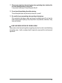
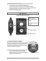
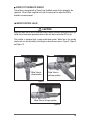
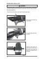
1
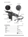
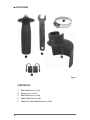
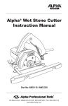
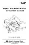
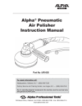
MANUAL
Alpha® Variable
Speed Wet Polisher
Instruction Manual
Model No.: VSP-120
WARNING: To reduce the risk of injury, user must read and understand instruction manual!
103 Bauer Drive, Oakland, NJ 07436 • 800-648-7229 • Fax: 800-286-0114
www.alpha-tools.com
TABLE OF CONTENTS
VSP-120 Overview ............................................................................................ 3
Specifications ............................................................................................. 3
Accessories ................................................................................................ 4
Introduction ........................................................................................................ 5
About the Symbols ..................................................................................... 5
General Safety Rules ........................................................................................ 6
Work Area ................................................................................................... 6
Electrical Safety .......................................................................................... 6
Personal Safety .......................................................................................... 6
Tool Use and Care ...................................................................................... 7
Service ....................................................................................................... 7
Specific Safety Rules.................................................................................. 8
Use Proper Extension Cords ...................................................................... 9
Grounding Instructions ............................................................................... 9
Additional Precautions for using the VSP-120.......................................... 10
Laws and Regulations Of Noise Levels .....................................................11
VSP-120 Variable Speed Wet Polisher Operation ........................................... 12
Main Connection ...................................................................................... 12
Switching On and Off................................................................................ 12
Ground Fault Circuit Interrupter (GFCI) .................................................... 13
Testing In-line GFCI Unit .......................................................................... 14
Variable Speed Adjustment ...................................................................... 14
Speed Pot Feedback Sensor ................................................................... 15
Water Control Valve .................................................................................. 15
Side Handle Installation ............................................................................ 16
Customizing Splash Guard ....................................................................... 17
Splash Guard Installation ......................................................................... 18
Profiler and other approved Spindle Attachments .................................... 19
Water-Feed Attachment ............................................................................ 19
Maintenance ................................................................................................... 20
Daily ......................................................................................................... 20
Periodic .................................................................................................... 20
Bearings and gears .................................................................................. 21
Carbon Brush Replacement .................................................................... 21
Rear Cover Removal ................................................................................ 22
Alpha® VSP-120 Schematic ............................................................................ 27
Alpha® VSP-120 Parts List .............................................................................. 28
Services and Warranty Information ................................................................. 30
Loaner Program ....................................................................................... 30
Need More Information ............................................................................ 30
Alpha® Tool Repair Service....................................................................... 31
Warranty ................................................................................................... 31
Appendix A...........................................................................................................i
2
VSP-120 OVERVIEW
Speed Adjuster
Power Switch
“C” Handle
Band Clamp
Water Valve
In-line GFCI
Center Water Feed
Water Line
Splash Guard
Garden Hose Adapter
Figure-1
SPECIFICATIONS
Working Power Supply ................................................... Single-phase AC, 50/60 Hz
Voltage ........................................................................... 120V
Plug Type ....................................................................... A (120V)
Amperage ....................................................................... 7A
Wattage .......................................................................... 800W
Motor .............................................................................. Single-phase
No Load .......................................................................... 500~2800 RPM
Polishing Disc Size ......................................................... 4”
Cord................................................................................ 10’ single-phase cable
Weight .......................................................................... 7.3 Lbs
Machine/Cord/GFCI/Water-Line/
Splash Guard
3
ACCESSORIES
COMPONENTS:
1.
2.
3.
4.
5.
4
Side Handle (Part No. 210074)
Wrench (Part No. 210073)
Band Clamp (Part No. 210088)
Splash Guard (Part No. 210089)
Spare Set of Carbon Brushes (Part No. 210048)
Figure-2
INTRODUCTION
Thank you for purchasing the Alpha® Wet Polisher. Please read this instruction manual
thoroughly to ensure safety and correct use of the polisher. Keep this manual in a place
where operators can access it easily whenever necessary.
ABOUT THE SYMBOLS
According to the hazard level, all safety notes in this manual are classified into “DANGER”,
“WARNING”, and “CAUTION”.
DANGER!
Death or serious personal injury is imminent when handling this
polisher incorrectly.
WARNING!
There is a possibility of death or serious personal injury when
handling this polisher incorrectly.
CAUTION!
There is a possibility of personal injury or property damage when
handling this polisher incorrectly.
NOTE: In some situations, failing to observe WARNING notes could result in death or
serious personal injury. Be sure to read and observe the safety notes to ensure
safety and correct use of the polisher.
ELECTRICAL SYMBOLS
The following show the symbols used for tool.
V
Volts
A
Amperes
Hz
Hertz
~ or a.c.
Alternating Current
n0
No load speed
…/min
Revolution or reciprocation per minute
kg
Kilograms
Protective Earth
5
CAUTION!
The following are important notes for products, operation, and maintenance applicable to
this polisher.
GENERAL SAFETY RULES
WORK AREA
•
•
•
Keep your work area clean and well lit. Cluttered benches and dark areas invite
accidents.
Do not operate power tools in explosive atmospheres, such as in the presence
of flammable liquids, gases, or dust. Power tools may create sparks which may
ignite the dust or fumes.
Keep bystanders, children, and visitors away while operating a power tool.
Distractions can cause you to lose control.
ELECTRICAL SAFETY
•
•
•
•
•
Grounded tools must be plugged into an outlet properly installed and grounded
in accordance with all codes and ordinances. Never remove the grounding prong
or modify the plug in any way. Do not use any adaptor plugs. Check with a qualified
electrician if you are in doubt as to whether the outlet is properly grounded. If the tools
should electrically malfunction or break down grounding provides a low resistance path
to carry electricity away from the user.
Avoid body contact with grounded surfaces, such as pipes, radiators, ranges, and
refrigerators. There is an increased risk of electric shock if your body is grounded.
Don’t expose power tools to rain or wet conditions. Water entering a power tool
will increase the risk of electric shock.
Do not abuse the cord. Never use the cord to carry the tools or pull the plug from an
outlet. Keep cord away from heat, oil, sharp edges, or moving parts. Replace damaged
cords immediately. Damaged cords increase the risk of electric shock.
When operating a power tool outside, use an outdoor extension cord marked
“W-A” or “W”. These cords are rated for outdoor use and reduce the risk of electric
shock.
PERSONAL SAFETY
•
•
•
6
Stay alert, watch what you are doing and use common sense when operating
a power tool. Do not use tool while tired or under the influence of drugs, alcohol, or
medication. A moment of inattention while operating power tools may result in serious personal injury.
Dress properly. Do not wear loose clothing or jewelry. Contain long hair. Keep your
hair, clothing, and gloves away from moving parts. Loose clothes, jewelry, or long hair
can be caught in moving parts or drawn into air vents.
Avoid accidental starting. Be sure switch is off before plugging in. Carrying tools with
your finger on the switch or plugging in tools that have the switch on, invites accidents.
•
•
•
•
•
•
•
•
•
•
•
Remove adjusting keys or wrenches before turning the tool on. A wrench or a
key that is left attached to a rotating part of the tool may result in personal injury.
Do not overreach. Keep proper footing and balance at all times. Proper footing and
balance enables better control of the tool in unexpected situations. Do not use on a
ladder or unstable support.
Use safety equipment. Always wear eye protection. Dust mask, nonskid safety
shoes, hard hat, or hearing protection must be used for appropriate conditions.
TOOL USE AND CARE
Use clamps or other practical way to secure and support the workpiece to a
stable platform. Holding the work by hand or against your body is unstable and may
lead to loss of control.
Do not force tool, use the correct tool for your application. The correct tool will do
the job better and safer at the rate for which it is designed.
Do not use tool if switch does not turn it on or off. Any tool that cannot be controlled
with the switch is dangerous and must be repaired.
Disconnect the plug from power source before making any adjustments, changing accessories, or storing the tool. Such preventive safety measures reduce the
risk of starting the tool accidentally.
Store idle tools out of the reach of children and other untrained persons. Tools
are dangerous in the hands of untrained users.
Maintain tools with care. Keep tools sharp and clean for better and safer performance.
Follow instructions for lubricating and changing accessories. Inspect the electrical cord
periodically and if damaged, have it repaired by authorized service facility. Inspect
extension cords periodically and replace if damaged. Keep handles dry, clean and
free from oil and grease.
Check for damaged parts. Before using the tool each day, a guard or other part
that is damaged should be carefully checked to determine that it will operate properly
and perform its intended function. Check for alignment of moving parts, breakage of
parts, mounting, and any other conditions that may affect its operation. A guard or
other part that is damaged should be properly repaired or replaced by an authorized
service center unless otherwise indicated elsewhere in this instruction manual. Have
defective switches replaced by authorized service center. Do not use the tool if it
cannot be turned on and off by the switch.
Use only accessories that are recommended by the manufacturer for your model.
Accessories that may be suitable for one tool, may become hazardous when used
on another tool.
SERVICE
•
•
Tool service must be performed only by qualified repair personnel. Service or
maintenance performed by unqualified personnel could result in a risk of injury.
When servicing a tool, use only identical replacement parts. Follow instructions in
the Maintenance section of this manual. Use of unauthorized part or failure to follow
Maintenance Instructions may create a risk of electric shock or injury.
7
SPECIFIC SAFETY RULES
•
•
•
•
•
•
•
•
•
•
•
•
•
•
•
8
Accessories must be rated for at least the speed recommended on the tool
warning label. Wheels and other accessories running over rated speed can fly apart
and cause injury.
Hold tool by insulated gripping surfaces when performing an operation where
the cutting tool may contact hidden wiring or its own cord. Contact with a “live”
wire will make exposed metal parts of the tool “live” and shock the operator.
Know your power tool. Read operator`s manual carefully. Learn its application and
limitations, as well as the specific potential hazards related to this tool. Following this
rule will reduce the risk of electric shock, fire, or serious injury.
Always wear safety glasses with side shields. Everyday eye-glasses have only
impact resistant lenses; they are NOT safety glasses.
Protect your lungs. Wear a face or dust mask if the operation is dusty.
Protect your hearing. Wear hearing protection during extended periods of operation.
Inspect tool cords periodically and if damaged, have repaired at your nearest Factory Service Center or other Authorized Service Organization. Constantly stay aware
of cord location.
Check damaged parts. Before further use of the tool, a guard or other part that is
damaged should be carefully checked to determine that it will operate properly and
perform its intended function. Check for alignment of moving parts, binding of moving
parts, breakage of parts, mounting, and any other conditions that may affect its operation, A guard or other part that is damaged should be properly repaired or replaced by
an authorized service center.
Do not abuse cord. Never carry the tool by the cord or yank it to disconnect it from
the receptacle. Keep cord away from heat, oil, and sharp edges. Following this rule
will reduce the risk of electric shock or fire.
Make sure your extension cord is in good condition. When using an extension
cord, be sure to use one heavy enough to carry the current your product will draw.
An undersized cord will cause a drop in line voltage resulting in loss of power and
overheating.
Inspect for and remove all foreign objects from workpiece before polishing.
Follow this rule will reduce the risk of serious personal injury.
Drugs, alcohol, medication, Do not operate tool while under the influence of
drugs, alcohol, or any medication. Follow this rule will reduce the risk of electric
shock, fire, or serious personal injury.
Keep hands away from polishing area. Follow this rule will reduce the risk of cuts,
scrapes, or serious personal injury.
Ground Fault Circuit Interrupter (GFCI) protection should be provided on the
circuit or outlet to be used for the tool. Receptacles are available having built-in
GFCI protection and may be used for this measure of safety.
Save these instruction. Refer to them frequently and use them to instruct others who
may use this tool. If you loan someone this tool, loan them these instructions.
USE PROPER EXTENSION CORDS
Use only three-wire extension cords that have three-prong grounding-type plugs and
three-pole receptacles that accept the tool’s plug. Make sure your extension cord is in
good condition. Replace or repair damaged or worn cord immediately. When using an
extension cord, be sure to use one heavy enough to carry the current your product will
draw. An undersized cord will cause a drop in line voltage resulting in loss of power and
overheating. Below table shows the correct size to use depending on cord length and
nameplate ampere rating. If in doubt, use the next heavier gauge. The smaller the gauge
number, the heavier the cord.
Ampere Rating
Total length of cord in feet (120V )
25ft
More Than Not More Than
50ft
100ft
AWG
0
6
18
16
16
6
10
18
16
14
10
12
16
16
14
12
16
14
12
Not Recommended
GROUNDING INSTRUCTIONS
This tool should be grounded while in use to protect the operator from electric shock. The
tool is equipped with a three-conductor cord and three-prong grounding type plug to fit
the proper grounding type receptacle. The green (or green and yellow) conductor in the
cord is the grounding wire. Never connect the green (or green and yellow) wire to a live
terminal.
9
ADDITIONAL PRECAUTIONS FOR USING THE VSP-120
In addition to the general safety notes described on the preceding pages, please read and
observe the following precautionary notes before using the polisher.
DANGER!
1.
2.
3.
4.
5.
6.
7.
8.
9.
Check the working voltage.
Be sure the voltage available at power outlet matches specified voltage on the nameplate. If the polisher is used with higher voltage than specified, the motor will burnout.
Any attempts to do so may damage the polisher or cause an accident or injury.
Inspect all polishing discs.
Never use cracked, chipped or damaged polishing discs.
Hold the polisher tightly at start-up.
Failure to do so may cause an injury due to high impact at initial start up.
Stop using the polisher immediately when noticing any malfunctions or any
suspicious abnormal noises.
Turn the power switch OFF and contact your dealer or Alpha Professional Tools® for
repair.
Handle the polisher with care.
If you accidentally drop the polisher, do not use it until checking that it is not cracked,
deformed, or damaged in any way.
Do not pour water or any liquids onto or inside the polisher.
It may cause electric shocks.
Do not hold the polisher in a vice.
Do not touch any rotating parts.
Never touch the polishing disc of the polisher during operation with your hands.
Do not leave the disc while spinning on the bench, floor or surface of your
workpiece.
It may cause an accident or injury.
WARNING!
10. Attach the backer pad and polishing disc correctly by following the procedure
in this instruction manual.
Attaching the polishing discs incorrectly may cause an accident.
10
11. Observe any suspicious abnormal noises when a polishing disc is attached for
the first time and polisher is turned ON.
It may cause bodily injury if the polishing disc flies off.
12. Do not touch the polishing disc while spinning.
The polishing disc spins very fast and you may hurt yourself.
13. Be careful of your surroundings when working in high places.
When working in high places, make sure there are no people below. Do not trap the
power supply cord on anything or drop the polisher or any materials, otherwise, It may
cause an accident.
LAWS AND REGULATIONS OF NOISE LEVELS
Please observe local laws and regulations regarding noise level in order to avoid disturbing
surrounding areas. Install a soundproof wall if required to comply with the local laws and
regulations.
11
VSP-120 VARIABLE SPEED WET POLISHER OPERATION
CAUTION!
Always be sure that the tool is switched off and unplugged before adjusting or checking
function on tool.
MAIN CONNECTION
Connect only to single-phase AC current supply and only to the main voltage specified on
the rating plate.
SWITCHING ON AND OFF
CAUTION!
Before plugging in the tool, always check the working voltage be sure that the voltage
specified is on the name plate. Before plugging in the tool, always check to see that the
slide switch actuates properly and returns to the “OFF” position when the rear of the slide
switch is depressed.
Switching on:
ON POSITION
Switch can be locked in “ ON” position for ease
of operator comfort during extended use. Apply
caution when locking tool in “ON” position and
maintain firm grasp on tool. Push power switch
to the forward position until it locks into position
as shown in Figure 3.
Figure-3
OFF POSITION
Switching off:
Push down on power switch to release to the
rear position as shown in Figure 4.
Figure-4
12
GROUND FAULT CIRCUIT INTERRUPTER (GFCI)
A Ground Fault Circuit Interrupter is built in-line with the power supply cord to protect
the operator from electric shock.
1. GFCI Information.
– Alpha® Wet Polisher is provided with an in-line GFCI as a standard accessory
for your safety, and to prevent possible electric shocks. It is strongly advised to
test the GFCI on a regular basis.
DANGER!
Never attach a damaged extension cord to the polisher.
NOTE: Use the appropriate extension cord, see table on page 9.
CAUTION!
When the GFCI trips, this could be the result of water entering the polisher housing.
1. Turn OFF the power switch, disconnect polisher from power supply and blow dry
air inside the motor cover through the air vents.
2. Re-connect power supply and press the GFCI reset button. The polisher is ready
to start working once the reset button is pressed down.
DANGER!
Always check that the GFCI unit is working correctly (reset, test, and reset) before using
this tool. Do not use the tool if the GFCI is not working correctly. Do not bypass the GFCI
if this condition occurs, a real shock hazard may exist.
WARNING!
If the GFCI fails to trip when the test button is pressed, or fails to reset, the device is defective and should replaced.
CAUTION!
1. The GFCI is a safety device, do not use as an on/off switch.
2. The GFCI on the tool will not protect you if you cut into another current carrying
conductor.
3. Do not use where water may enter GFCI case.
13
TESTING IN-LINE GFCI UNIT (Before Each Use Of The Polisher)
1. Connect polisher to a single phase AC power supply.
2. Verify that the indicator lens shows red (indicating output voltage).
3. Press the test button to verify that the red in the indicator lens disappears.
4. Press the reset button to verify the red indicator is visible.
5. The GFCI is now ready for use.
WARNING!
DO NOT USE IF ABOVE TEST FAILS!
Indicator viewing lens.
RED lens shows power to
polisher.
CLEAR lens shows no power
to polisher.
RESET BUTTON
TEST BUTTON
Figure-6
Figure-5
VARIABLE SPEED ADJUSTMENT
This polisher is equipped with a Variable Speed control that
will allow the spindle speed to be adjusted from 500 RPM
to 2800 RPM. Speed adjustment is controlled by rotation
of the wheel as shown in the Figure 4.
DECREASE SPEED
INCREASE SPEED
NOTE- Wheel numbers are for reference point of motor
speed (#1 is 500 RPM and #6 is 2800 RPM).
Adjust the RPM of the tool to match the recommended
RPM of the product being used.
14
Figure-7
SPEED POT FEEDBACK SENSOR
This polisher is equipped with a Closed Loop Feedback sensor that is attached to the
speed pot. When a load is applied to the tool, the sensor will re-adjust the RPM to
maintain a constant speed.
WATER CONTROL VALVE
CAUTION!
Adjust the water flow to wet the stone and remove waste, excessive spray and mist will get
inside the tool and cause premature failure of the tool and/or cause the GFCI to trip.
This polisher is equipped with a center water-feed system. Water flow to the spindle
shower bolt can be controlled by throttling the valve stem as seen in Figure 8, Figure 9
and Figure 10.
Water Valve in
closed position
Water Valve in
half open position
Figure-9
Figure-8
Water Valve in full open position
Figure-10
15
SIDE HANDLE INSTALLATION
CAUTION!
During the use of Alpha® Core Bits and Profilers, use of the center handle is recommended.
The center handle will allow the operator to have better control and ease of operation
during these applications.
To switch from center handle to side handle, follow the steps below:
Remove both side screws from
center handle.
Figure-12
Pull handle forward and clear
of polisher.
Figure-13
Thread the side handle into
either the left or right side of
the polisher, then thread one
screw into the opposite side of
the handle.
Figure-14
16
CUSTOMIZING THE SPLASH
GUARD
The splash guard can be cut to different
heights according to the application to be
performed.
Cutting: Using a pair of scissors or other
cutting instrument,
choose the desired
height according to
the application to be
performed and cut
along the grooved
cut lines, as shown in
Figure 15.
Grooved Cut Lines
Figure-15
RECOMMENDED HEIGHTS:
Profiling: When using Alpha® Profilers the
splash guard can be used at its full height.
Full height
Figure-16
Polishing: When polishing, you may cut the
splash guard at one of the grooved lines for easier
access to the workpiece.
Splash Guard cut to
accomodate polishing
application
Figure-17
17
SPLASH GUARD INSTALLATION
CAUTION!
The splash guard should be used to prevent the water and
dust from going inside the tool. Failure to do so can shorten
the life of your tool and void the limited warranty.
1.
Install the rubber splash guard into
the tool so that the lip on the splash
guard fits into the groove on the tool
and the cutout is around the water
fitting.
2.
Open the band clamp completely
and wrap around the splash guard
under the water fitting.
3.
Tighten the clamp until snug.
Groove
Figure-18
Figure-19
Figure-20
18
PROFILER AND OTHER APPROVED SPINDLE ATTACHMENTS
CAUTION!
Do not leave threaded accessories on the spindle of the tool for extended periods of time,
as this may result in making it difficult to remove these accessories.
The VSP-120 polisher has a 5/8”-11 center water-feed spindle thread.
To attach a profiler wheel or other approved spindle attachments, follow the
steps below:
1.
Screw the attachment onto the
spindle by hand.
Figure-21
2.
Tighten with supplied wrench.
NOTE : If attachment does not thread on
freely, check threads on both surfaces for damage or dirt. Clean,
repair or replace as needed to
ensure a safe and tight connection to the polisher.
Figure-22
WATER-FEED ATTACHMENT
Attach the polisher water-line fitting to any garden hose connection.
OPERATION
WARNING!
To reduce the risk of electric shock, check the tool’s water supply system to ensure there is
no damage to the seals or hoses. A damaged water supply system may result in abnormal
water flow to the tool which could be dangerous.
19
CAUTION!
Always wear safety goggles or a face shield during operation. Never switch on the tool
when it is in contact with the workpiece, it may cause an injury to operator. Never run the
tool without properly installed accessories.
Make sure that the water valve is closed. Connect the garden hose adapter to the water
source. Make sure that water comes out when the water valve is opened. Hold the tool
firmly. Turn the tool on and begin your application. Apply slight pressure only. Excessive
pressure will result in poor performance and premature wear.
MAINTENANCE
CAUTION!
Always be sure that the tool is switched off and unplugged before attempting to perform
inspection or maintenance.
DAILY
1.
2.
3.
4.
5.
Before daily start-up inspect tool, power cord, GFCI, and backer pad or other spindle
attachments.
If damage has occurred, repair affected areas before use.
Connect the tool to the correct power source and test the Ground Fault Circuit Interrupter (GFCI) before using the tool. Push the RESET button and confirm that the red
light is on, push the TEST button and confirm that the red run light is off and push the
RESET button to use the tool.
Turn the unit on and run in a no-load condition to ensure that backer pad or other
spindle attachment is balanced.
After daily use of the tool, clean and blow off the exterior of tool and around the rear
air intake vents to remove any standing water or dust. Failure to do this will shorten
the life of your tool, and could void your warranty.
PERIODIC
WARNING!
Preventive maintenance preformed by unauthorized personnel may result in misplacing
of internal wires and/or components which voids the warranty and could cause serious
hazards. We recommend that tool service and repairs not covered in the manual be
preformed by an Alpha® Repair Center.
20
Periodic maintenance is done to check the tool and to minimize down time. These checks
are done based on hours of operation and operating conditions. Operating condition can
vary depending on the work surface and job being preformed. If the tool is not used for a
long period of time the carbon brushes should be checked and the commutator cleaned,
before putting the tool back into operation.
BEARINGS AND GEARS
To minimize your tool’s down time and expensive tool repairs, it is recommended to send
the tool back to an Alpha® Repair Center after about 300 to 400 hours of operation or every
second carbon brush set change. The bearings should be replaced and the gears should be
checked. If your tool starts to sound differently, this could be an indication of a worn bearing;
continuing to use the tool in this condition could result in over heating or motor failure.
CARBON BRUSH REPLACEMENT
Carbon brushes wear out over time, based on the polisher usage. If a carbon brush is worn
out, it may cause the motor to malfunction or fail to run. Whenever the length of the carbon
brush reaches the wear limit, replace with a new set.
NOTE - To maintain even wear, both brushes should be replaced at the same time.
The carbon brushes in this polisher are located underneath the Rear Cover (Part # 210053)
as shown in Figure 23.
Carbon brushes are located under the rear cover
Figure-23
21
REAR COVER REMOVAL
1.
Gently pull water tube away from
holder.
Figure-24
2.
Release the tube from the holder.
Figure-25
3.
Unwrap 3 inches of the coiled
harness.
Figure-26
4.
Remove the 2 screws from the valve
bracket.
Figure-27
22
5.
Pull the valve assembly away from
mount.
Figure-28
6.
Remove the rear case screw.
Figure-29
7.
Hold polisher with one hand and pull
the rear case straight back with the
other hand.
NOTE: Do not twist case in a side to side
motion when pulling back.
Figure-30
8.
Pull back the rear case until the
carbon brush assembly is exposed.
NOTE: Do not pull rear case further back
from this point.
Figure-31
23
Carbon Brush
Spring
Carbon Brush
Holder
Carbon Brush
Wire
Figure-32
9.
Lift the spring from the carbon
brush and place on the side of
the brush holder.
Figure-33
10. Remove the carbon brush wire spade connector from the terminal post and then remove
the carbon brush.
Spade Connector
Figure-34
24
Figure-35
11. You can also remove the carbon brush by
removing the screw and pulling the holder out
with a pair of needle nose pliers.
12. With the carbon brush holder removed, you can
check and clean the armature commutator. The
commutator is the contact points that the carbon
brushes ride on when the motor is running.
Figure-36
NOTE: Each polisher has 2 carbon brushes located on opposite sides of each
other. After the replacement of the two brushes, assemble the polisher by reversing
disassembly procedure.
13. Check the carbon brush for wear. Replace if worn down to a 1/4" .
New Carbon Brush
Figure-37
Old Carbon Brush
worn down to a quarter
of an inch (1/4”).
14. Blow dust off of the spring and check for proper tension.
15. Remove the old carbon and disconnect the wire terminal wire. If the inside of the holder
is filled with dust, clean before installing the new carbon brush. Upon installation of
the new carbon brush, make sure the twisted wire is in the slot and behind the wire
terminals on holder as in the photo above.
25
16. The commutator should be clean and shiny; if it is dull and black, you can clean it with
a commutator cleaning stone.
Clean
Dirty
Figure-38
Figure-39
17. To clean the commutator, press the commutator cleaning stone against the commutator
and rotate the armature by turning the spindle shaft by hand. Continue for a minute
or until commutator is clean and shiny.
Figure-40
18. Reconnect the power wire, ensuring that the wire path is correct. Reinstall the carbon
brush holder into the slot on motor housing and slide in until the tab for the screw hits
the stop. Install the screw using light pressure to prevent it from stripping.
19. After both carbon brushes have been replaced you can reassemble the rear cover.
Make sure the power wires are in the tool to prevent pinching of the wires.
26
ALPHA® VSP-120 SCHEMATIC
Revised: 01/2008
27
ALPHA® VSP-120 PARTS LIST
DRAWING NO.
PART NO.
1
210001
Screw M4x12
4
2
210002
Spring Washer 4
5
3
210003
Plain Washer 4
4
4
210004
Shower Bolt
1
5
210005
Output Shaft 120V (5/8"-11)
1
6
210006
Key 3x10
2
7
210090
Gear Case Cover
1
8
210008
Oil lip seal B16x28x7D
2
9
210009
Bearing Washer
1
10
210010
Ball bearing 6201
1
11
210011
Gear Washer
1
12
210012
Thrust Bearing 15x28x6
1
13
210013
Bearing Clamp
1
14
210014
Spring Washer 5
4
15
210015
Screw M5x16
4
16
210016
Gear
1
17
210017
Wave Spring Lock Washer 10
1
18
210018
“C” clip for Shaft 10
1
19
210019
Oil-impregnated Bearing 8x12x8
2
20
210020
Spindle-Lock Pin
1
21
210021
Self-tapping Screw 4.2x45
2
22
210022
Case Plastic Cover
1
23
210023
Screw M10x20
2
24
210024
C-Handle
1
25
210025
Lock Pin Cap
1
26
210026
Pin Spring
1
27
210027
Gear Case
1
28
210028
Anti-loose Nut M6
1
29
210029
Pinion Z3
1
30
210030
Transmitting Shaft
1
31
210031
Ball Bearing 6200
1
32
210032
Bevel Gear Z2
1
33
210033
Screw M4x8
2
34
210034
Bearing Retainer
1
28
DESCRIPTION
QUANTITY
ALPHA® VSP-120 PARTS LIST
DRAWING NO.
PART NO.
DESCRIPTION
QUANTITY
35
210035
O-Ring 21.2x1.8
1
36
210036
Ball Bearing 608
1
37
210102
Armature 120V
1
38
210038
Ball Bearing 607
1
39
210039
Rubber Bearing Seat
1
40
210040
Windshield
1
41
210041
Self-tapping screw 4.2x70
2
42
210042
Field Coil 120V
1
43
210099
Brand Label
1
44
210091
Field Coil Case
1
45
210092
Data Label
1
46
210046
Carbon Brush Holder
2
47
210047
Coil Spring
2
48
210048
Carbon brush 120V (PM825)
2
49
210049
Self-tapping screw 2.9x8
2
50
210094
Terminal Block
2
51
210093
Speed Pot w/Feed-Back Sensor 120V
1
53
210053
Rear Cover
1
54
210054
Self-tapping screw 4.2x14
3
55
210055
Cord Jacket
1
56
210056
Twist Strip
1
57
210057
Rubber Washer
1
58
210058
Garden Hose Adapter
1
59
210059
Spring
1
61
210061
Power Supply Cord 120V
1
62
133229
Water Hose 8mm ODx10ft (3m)
1
63
210063
Water Valve Bracket (for VSP-120)
1
64
210064
Water Valve Assembly (for VSP-120)
1
65
210065
Water Hose 6mm ODx8in (20cm)
1
66
210066
Cord Clamp
1
67
210067
Outlet Tap
1
68
210068
Switch
1
69
210069
Back Moving Spring
1
70
210070
Switch Push Lever
1
29
ALPHA® VSP-120 PARTS LIST
DRAWING NO.
PART NO.
DESCRIPTION
QUANTITY
71
210071
Switch Push Button
1
72
210072
GFCI 120V (American)
1
73
210073
Wrench (for VSP-120)
2
74
210074
Side Handle (for VSP-120)
1
75
210075
O-Ring 15x2.65
1
76
210076
Dash Panel
1
77
210077
Self-tapping screw 4.2x40
2
78
210078
Self-tapping screw 4.2x10
2
79
210079
Water Valve Tap
1
(not shown)
210087
BMC (Blow Mold Case) for VSP-120
1
80
210088
Band Clamp
1
81
210089
Splash Guard
1
82
210095
Magnetic Ring
1
83
210096
Screw M4x8
1
84
210097
Terminal Connector
1
SERVICES AND WARRANTY INFORMATION
LOANER PROGRAM
Loaner tools can be issued to temporarily replace a tool that is being returned to Alpha®
for repair. If more than one tool is being returned for repair, the number of loaner tools
provided will be based on availability.
If a loaner tool is required, contact Alpha® Tool Department at (800) 648-7229 to receive a
Loaner Tool Application. A valid credit card number must be provided as a security deposit.
The credit card will only be charged if the loaner tool is not returned to Alpha® within 30 days.
An authorized signature is required for the credit card being used. A second signature is
required as an agreement of the overall policy.
NEED MORE INFORMATION
For information on Alpha Professional Tools® complete product line, visit us on the web at
www.alpha-tools.com
30
ALPHA® TOOL REPAIR SERVICE
For more information concerning Alpha® tool repair service, please contact the
Alpha® repair centers listed below:
COMPANY HEADQUARTERS:
Alpha Professional Tools®
103 Bauer Drive
Oakland, NJ 07436
Hours of Operation:
8:30 a.m. – 5:00 p.m. EST
Telephone Number:
201-337-3343
Toll-Free Number:
800-648-7229
FACTORY SERVICE AND
TRAINING CENTER:
3625 W. Teco Ave.,
Suite #5
Las Vegas, NV 89118
Hours of Operation:
7:30 a.m. – 4:00 p.m. PST
Telephone Number:
702-837-9515
Toll-Free Number:
888-292-5742
WARRANTY
Limited Warranty of Alpha® Wet Polisher for the USA and Canada ONLY!
Alpha Professional Tools® warrants this product against defects in material and
workmanship for a period of 180 days from the date of original retail purchase (proof
of purchase required). If Alpha Professional Tools® receives notice of such defects
during the warranty period, our obligation assumed under this warranty is limited to
the repair or replacement of parts, without charge. This warranty does not apply to
tool accessories.
For Warranty Claims: Send complete tool with all your information and details of the
problem to your nearest Alpha® Repair Center, transportation prepaid. Do not send
tool accessories.
31
APPENDIX A
FREQUENTLY ASKED QUESTIONS
Q. What applications is the Alpha® VSP-120 recommended for?
A. The Alpha® VSP-120 is recommended for wet polishing, wet core drilling, profiling
and grinding.
Q. What is the warranty for this VSP-120?
A. Alpha Professional Tools® warranties the VSP-120 against defects in material and
workmanship for a period of 180 days from the date of original retail purchase
(proof of purchase required). Please complete the warranty registration card
upon receipt and mail immediately for prompt warranty service. Our obligation
assumed under this warranty is limited to the repair or replacement of parts
without charge. The warranty does not apply to tool accessories. The warranty
for repairs is 30 days on the parts and labor.
Q. Does the VSP-120 have a maintenance program?
A. Alpha Professional Tools® does not offer any type of maintenance program.
However, we do recommend periodic checking and/or replacement of the carbon
brushes for extended service life. If you should hear or detect unusual noise
during the operation of the VSP-120, we recommend that you send it in to our
repair department for some preventative maintenance.
Q. What is the RPM of the VSP-120?
A. This polisher is a variable speed polisher with an RPM range of 500 – 2,800.
Q. What shall I do if my VSP-120 breaks down and I need to complete the job
immediately?
A. This largely depends upon the time frame involved. The first step would be
to check and replace the carbon brushes. Alpha Professional Tools® has two
warranty service centers and can turn your tool repair around in a 3-5 day period.
Please contact Alpha® for information or send tool to your nearest regional repair
center. For additional information or alternative solutions. please contact our
tool repair department.
32
Q. The GFCI is tripping frequently. What I can I do?
A. If the GFCI is tripping frequently, there could be several problems.
1. Water is getting inside the polisher. Dry the tool with compressed air and try
to prevent water from getting into the polisher.
2. The voltage drops due to sharing the same power source in a work area.
3. Too much force is applied to the tool. Back-off on the pressure.
4. The outlet may be loose. Make sure the power cord plug is tightly inserted
in the power outlet.
5. Contact Alpha Professional Tools® tool repair department for further advice.
Q. If my VSP-120 breaks down, whom should I contact for repair?
A. Contact the dealer where you purchased the tool or Alpha Professional Tools®
directly at 800-648-7229.
Q. Can I use my VSP-120 as a wet cutting tool with a diamond blade?
A. No. The VSP-120 only has a 2,800 no load RPM rating. This is not enough RPM
for cutting applications with a diamond blade. It is unsafe to use the VSP-120
as a cutting tool. Do not attempt to cut with the VSP-120.
Q. Can I use my VSP-120 for dry polishing applications?
A. No. The VSP-120 is designed for wet use only. Alpha® recommends using our
AWP-158/214 for dry polishing applications.
Q. How can I get the parts list and schematic for the VSP-120?
A. There are several ways to obtain information such as this from Alpha Professional
Tools®. It is available on our website www.alpha-tools.com or by contacting our
Tool Dept Help Desk at 800-648-7229.
Q. What is the proper RPM for polishing Engineered Stone?
A. Any RPM range on this polisher will work for polishing engineered stone. Using
slower RPM together with the Alpha® Ceramica EX will provide the optimum
polish on engineered stone material.
i
Q. What is the largest diameter accessory that the VSP-120 will accept?
A. The VSP-120 will accept accessories up to 5”. Do not attempt to use accessories
larger than 5” for safety reasons. In addition, large accessories require more
torque than the VSP-120 can provide. Operating the VSP-120 under these
conditions will result in overheating failure.
Q. Can I use the VSP-120 for drilling applications such as faucet holes?
A. Yes. The VSP-120 can be used with Alpha® Core Bits to drill faucet mounting holes.
We recommend using the provided C-Handle attachment and a template.
Q. How many gallons of water does the Alpha® VSP-120 use per minute?
A. The Alpha® VSP-120 has a throughput of approximately 1.1 gallons per minute
with the water valve fully open.
HELPFUL HINTS
1.
If your VSP-120 does not start, check the carbon brushes for proper seating.
2.
If the VSP-120 does not re-start, check and reset the GFCI.
3.
Avoid dragging the VSP-120 on top of stone surfaces. The aluminum body may leave
marks on the surface.
4.
The C-Shape handle attached to the polisher is highly recommended for more stability
of the polisher during certain applications such as: surface polishing, core drilling and
profiling.
ii
PRODUCT REGISTRATION CARD
Model No.
Serial No.
Company Name: ______________________________________________
Name: ______________________________________________________
Address: ____________________________________________________
City: _______________________State: ________Zip: ________________
Telephone: ___________________________________________________
Purchase Date: _______________________________________________
Dealer’s Name: _________________________________
Note: Serial & Model Number must be included for proper registration.
(800) 648-7229
Register online at:
www.alpha-tools.com/productregistration.aspx
Mail or Fax to:
Alpha Professional Tools®
103 Bauer Drive, Oakland, NJ 07436
Fax: 800-286-0114
103 Bauer Drive, Oakland, NJ 07436 • 800-648-7229 • Fax: 800-286-0114
www.alpha-tools.com
Copyright © 2007 Alpha Professional Tools. All rights reserved.
Assembled in China
Revised: 11/2007