1
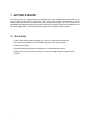
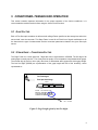
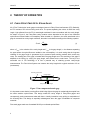
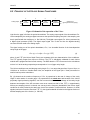
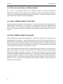
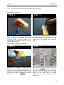
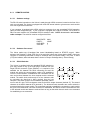
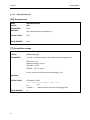
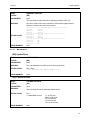
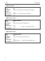
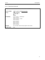
Veloce 50 Fiber Optic Temperature Monitor User Guide MAN-00029 R7 If the equipment described herein bears the symbol, the said equipment complies with the applicable European Union Directive and Standards mentioned in the Declaration of Conformity. LEGAL NOTICE AND DISCLAIMER PRODUCTS DESIGNED, MANUFACTURED AND SOLD BY FISO TECHNOLOGIES INC. (“FISO”), OR ITS AUTHORIZED DISTRIBUTORS, AGENTS OR RESELLERS, ARE NOT AND SHALL NOT BE CONSIDERED OR REPRESENTED AS BEING APPROVED OR CERTIFIED, NOR SUBMITTED FOR APPROVAL OR CERTIFICATION, BY APPLICABLE REGULATORY BODIES. FISO GENERALLY WARRANTS THAT ITS PRODUCTS SHALL BE FREE FROM DEFECTS IN MATERIAL AND WORKMANSHIP UNDER CONDITIONS OF NORMAL USE, AS PROVIDED IN THE FISO PRODUCT WARRANTY. FISO DISCLAIMS ALL OTHER LIABILITY WITH RESPECT TO ANY AND ALL USE OF ITS PRODUCTS, INCLUDING ALL EXPRESSED OR IMPLIED WARRANTIES OF MERCHANTABILITY AND FITNESS FOR PURPOSE. IN NO EVENT SHALL FISO, ITS SHAREHOLDERS, DIRECTORS, EMPLOYEES, AGENTS, OR RELATED CORPORATIONS OR ENTITIES, BE LIABLE FOR ANY DIRECT, INDIRECT, PUNITIVE, SPECIAL, INCIDENTAL, OR CONSEQUENTIAL DAMAGES IN CONNECTION WITH OR RELATED TO THE PURCHASE, TRANSPORTATION, INSTALLATION OR USE OF FISO PRODUCTS (INCLUDING LOSS OF PROFITS, USE, OR OTHER ECONOMIC ADVANTAGE), HOWEVER ARISING, WHETHER FOR BREACH OF WARRANTY OR IN TORT, EVEN IF FISO HAS BEEN PREVIOUSLY ADVISED OF THE INTENDED USE OF ITS PRODUCTS OR OF THE POSSIBILITY OF SUCH DAMAGE. FISO PRODUCTS ARE SCIENTIFIC INSTRUMENTS THE MISUSE OF WHICH IS POTENTIALLY DANGEROUS. THEY ARE INTENDED TO BE INSTALLED AND USED ONLY BY QUALIFIED PERSONNEL, IN ACCORDANCE WITH FISO PRODUCT DOCUMENTATION, MANUALS, GUIDELINES AND INSTRUCTIONS. THE INFORMATION CONTAINED IN SUCH DOCUMENTATION, MANUALS, GUIDELINES AND INSTRUCTIONS IS BELIEVED TO BE ACCURATE AND RELIABLE, BUT MAY BE MODIFIED WITHOUT NOTICE. THE INFORMATION CONTAINED IN FISO DOCUMENTATION, MANUALS, GUIDELINES AND INSTRUCTIONS IS SUBJECT TO COPYRIGHT PROTECTION UNDER THE BERNE CONVENTION. NO PART OF THE DOCUMENTATION, MANUALS, GUIDELINES AND INSTRUCTIONS MAY BE REPRODUCED OR TRANSMITTED IN ANY FORM OR BY ANY MEANS ELECTRONIC OR MECHANICAL, INCLUDING PHOTOCOPYING, OR BY ANY INFORMATION STORAGE AND RETRIEVAL SYSTEM, WITHOUT PRIOR WRITTEN PERMISSION FROM FISO. ALL INFORMATION CONTAINED IN FISO DOCUMENTATION, MANUALS, GUIDELINES AND INSTRUCTIONS REMAINS THE EXCLUSIVE PROPERTY OF FISO. TRADEMARKS AND TRADENAMES MENTIONED IN FISO PRODUCT DOCUMENTATION, MANUALS, GUIDELINES AND INSTRUCTIONS ARE THOSE OF THEIR RESPECTIVE OWNERS. THE USE OF SUCH TRADEMARKS AND TRADENAMES SHOULD NOT BE CONSTRUED AS A CHALLENGE TO THEIR OWNERSHIP BY FISO. NWNAD-05/01/2004 IMPORTANT SAFETY INSTRUCTIONS This symbol appears on the identification label at the back of the unit. It refers to important safety notices that can be found in this manual When using any electrical appliance, basic safety precautions should be followed, including the following: For indoors uses ONLY Do not operate in wet/damp conditions Do not operate in an explosive atmosphere Keep product surfaces clean and dry i Veloce 50 Operating Manual Contents LEGAL NOTICE AND DISCLAIMER ..........................................................................................i IMPORTANT SAFETY INSTRUCTIONS.....................................................................................i 1 Getting Started.........................................................................................................................1 1.1 2 Description of the Veloce System............................................................................................2 2.1 2.2 2.3 2.3.1 2.3.2 2.3.3 2.3.4 3 7.2.1 7.2.2 7.3 7.4 7.4.1 7.4.2 ii Gage Factor.................................................................................................................................. 8 Strain Gage – Conversion Factor ................................................................................................. 8 Fabry-Pérot Fiber Optic Strain Gages.......................................................................................... 9 Principle of the Veloce Signal Conditioner ............................................................................... 10 Relative versus Absolute Measurements ................................................................................... 11 Absolute Measurement Conditioner .......................................................................................... 11 Relative Measurement Conditioner ........................................................................................... 11 Maintenance ..........................................................................................................................13 7.1 7.2 8 Mating the Transducers to the Veloce Conditioner ..................................................................... 7 Using the Fiber-Optic Transducers .............................................................................................. 7 Theory of operation .................................................................................................................9 6.1 6.2 6.3 6.4 6.5 7 Line Power Connection................................................................................................................ 5 Cooling and Installation ............................................................................................................... 6 Conditioner–Transducer Operation .......................................................................................8 5.1 5.2 6 Status LED ............................................................................................................................................. 3 Transducer Input .................................................................................................................................... 3 Analog Output........................................................................................................................................ 4 Reset Button ........................................................................................................................................... 4 Taking Measurements.............................................................................................................7 4.1 4.2 5 Front............................................................................................................................................. 2 Back ............................................................................................................................................. 2 Module Front Panel...................................................................................................................... 3 Installation...............................................................................................................................5 3.1 3.2 4 Quick Start ................................................................................................................................... 1 Replacing the fuse...................................................................................................................... 13 Connector cleaning procedure ................................................................................................... 13 Information on general fiber-optic applications ................................................................................... 13 How to clean the transducers and conditioner connectors.................................................................... 14 How to prevent damage and ensure a long life to your transducers .......................................... 15 Preventive maintenance ............................................................................................................. 15 Inspection ............................................................................................................................................. 15 Cleaning ............................................................................................................................................... 15 Specifications.........................................................................................................................16 Veloce 50 Appendix A Operating Manual COMMUNICATION VIA RS-232 PORT ...........................................................17 8.1.1 CONVERSION FROM VOLTAGE TO DEGREES CELCIUS ......................................................... 17 8.1.2 ADJUSTABLE PARAMETERS (REMOTE CONTROL).................................................................. 17 8.1.2.1 Voltage output span .................................................................................................................... 17 8.1.2.2 Signal averaging ......................................................................................................................... 18 8.1.2.3 System reset................................................................................................................................ 18 8.1.2.4 Zeroing ....................................................................................................................................... 18 8.1.2.5 Versions...................................................................................................................................... 18 8.1.3 REMOTE CONTROL.......................................................................................................................... 19 8.1.3.1 Hardware settings ....................................................................................................................... 19 8.1.3.2 Hardware flow control................................................................................................................ 19 8.1.3.3 RS-232 Switches......................................................................................................................... 19 8.1.3.4 Remote Control Commands........................................................................................................ 20 8.1.3.5 Analog Output ............................................................................................................................ 22 8.1.3.6 Reading Parameters .................................................................................................................... 23 8.1.3.7 Miscellaneous ............................................................................................................................. 24 8.1.3.8 Remote Special Commands ........................................................................................................ 26 List of Figures Figure 1 Veloce module front panel overview.................................................................................3 Figure 2 Gage Length given by last five digits ................................................................................8 Figure 3 Non-compensated strain gage............................................................................................9 Figure 4 Schematic of the operation of the Veloce ........................................................................10 Figure 5 Schematic explanation of relative measurements. ...........................................................12 iii 1 GETTING STARTED The Veloce System is a high-speed and universal fiber-optic signal conditioning instrument that can be used to perform relative Strain, Temperature, Force & Load, and Pressure measurements in hostile locations that were formerly inaccessible with other measuring instruments. The Veloce System is an expandable instrument that can accept up to eight Veloce plug-in modules. Each Veloce conditioner has a 200 kHz sampling speed. The following sections explain how to operate the Veloce System. 1.1 QUICK START • Power on the Veloce System (let it heat-up for one hour for optimum performances); • Plug a fiber optic transducer in the Transducer Input port of the Veloce module; • Press the reset button; • Plug the Analog output port to an oscilloscope or to a data acquisition system; • Read section 6 of this manual to know how to convert the voltage output to a physical value; • That's it! 1 Veloce 50 Operating Manual 2 DESCRIPTION OF THE VELOCE SYSTEM 2.1 FRONT Modules RS-232 Port 2.2 BACK AC inlet module with integrated switch and fuse holder Exhaust fans Identification label 2 Veloce 50 Operating Manual 2.3 MODULE FRONT PANEL The Veloce Module front panel essentially consists of the fiber optic Transducer (sensor) Input connector (ST type), the Analog (voltage) Output connector (BNC type), a Reset Button and two (green and red) Status LEDs. VELOCE-50 READY CHECK RESET SENSOR INPUT ANALOG OUTPUT F I S O T E C H N O L O G I E S Figure 1. Veloce module front panel overview 2.3.1 STATUS LED The green LED (READY) indicates that the Veloce is currently acquiring and processing data. The red LED (CHECK) is turned on while the reset is activated, or indicates a malfunction of the system. 2.3.2 TRANSDUCER INPUT The fiber optic transducer connects to the Veloce Module via the ST-type fiber optic connector. See section 7.3 for the precautions that have to be taken when mating a transducer to the Veloce Module. 3 Veloce 50 2.3.3 Operating Manual ANALOG OUTPUT The analog output gives a voltage proportional to the value of the physical parameter measured by the fiber optic transducer. The analog output is a BNC-type coaxial connector. See section 6 for converting the voltage output value to the measured physical parameter value. 2.3.4 RESET BUTTON The Reset Button zeroes out the analog output of the Veloce Module. The «Reset» button has to be pressed each time a transducer is connected to the Transducer Input. When the Reset Button is pressed, all reference to the previous measurements is lost, thus making the Veloce a relative measurement instrument. The Veloce module takes approximately 1 second to settle after the Reset Button has been pressed. 4 Veloce 50 Operating Manual 3 INSTALLATION 3.1 LINE POWER CONNECTION 1. Check to see that the line voltage is within the limits specified above; CAUTION: Operating the instrument on an incorrect line voltage may cause damage to the instrument, possibly voiding the warranty. 2. Before plugging in the power cord, make sure that the power switch is in the off (0) position; 3. Connect the female end of the supplied power cord to the AC receptacle on the rear panel. Connect the other end of the power cord to a grounded AC outlet; WARNING: The power cord supplied with the Veloce System contains a separate ground wire for use with grounded outlets. When proper connections are made, instrument chassis is connected to power line ground through the ground wire in the power cord. Failure to use grounded outlet may result in personal injury or death due to electrical shock. 4. Turn on the instrument by setting the power switch on the rear panel to the on (1) position. The Green Status LED indicator will lit up on each Veloce module approximately 1 second after power up, showing that it is working and that acquisition and processing has started. Either the power cord or the AC mains switch are used as disconnecting device; make sure that they remain accessible at all time after installation of the unit 5 Veloce 50 Operating Manual 3.2 COOLING AND INSTALLATION The Veloce SYSTEM is cooled by forced convection. Two exhaust fans located on the rear panel allow ambient air to flow outside the chassis of the instrument. The ambient air is drawn inside the casing from the ventilation louvers located on the bottom cover to the fans. CAUTION: The Veloce System chassis must be installed in area where ambient temperature does not exceed 40°C. Enough space must be allowed for exhaust fans and ventilation louvers so they are not obstructed and sufficient ventilation is provided. Operating the instrument with improper cooling may cause damage to the instrument, possibly voiding the warranty. 6 Veloce 50 Operating Manual 4 TAKING MEASUREMENTS 4.1 MATING THE TRANSDUCERS TO THE VELOCE CONDITIONER To use a transducer with the Veloce conditioner, simply mate the fiber optic transducer connector with the Veloce input connector. Once the transducer is connected, simply press the reset button and valid readings of the transducer will be present at the Analog Output connector. See section 6 for converting the voltage output value to the measured physical parameter value. For proper use of the fiber optic transducers, the transducer fiber optic connectors must be kept clean and free of dust at all times. Any dust may obstruct the light transmitted from one connector to the other, and reduce the signal-to-noise ratio to an unusable level. IT IS A GOOD PRACTICE TO ALWAYS CLEAN THE TRANSDUCER CONNECTOR BEFORE MATING IT TO THE CONDITIONER (SEE SECTION 6). Transducer connectors are cleaned by wiping its end with low lint tissue such as Kimwipes® or lens cleaning tissue. Keeping the transducer connectors clean also prevents the contamination of the Veloce input connector. However, it is also recommended to clean the Veloce input connector once in a while. Use the specially designed 2.5 mm Mini Foam Swab provided with Fiso Cleaning Kit (Part n° FTI-M) for cleaning the input connector of Veloce. 4.2 USING THE FIBER-OPTIC TRANSDUCERS Additional information are available on specific fiber-optic transducers. Ask for Fiso Technologies specific technical note and installation guide such as Fiso Fiber-Optic Strain Gauge Installation Guide. 7 5 CONDITIONER–TRANSDUCER OPERATION This section contains important information for the proper operation of the Veloce conditioner. It is recommended to read this section before using the Veloce for the first time. 5.1 GAGE FACTOR Each of Fiso fiber optic transducer is delivered with a Gage Factor specified on the storage box and on the sensor itself, near the connector. This Gage Factor is used for all Fiso's line of signal conditioners to tell the instrument the type of measurement and the conversion parameters related to the given fiber optic sensor. 5.2 STRAIN GAGE – CONVERSION FACTOR The Gage Factor for a strain gage has 7 digits that can be expressed as 1XSSSSS. The first digit of all strain gages is usually equal to 1, but it may also be equal to 5 for temperature compensated strain gages. The second digit (X) has no role to play other than to differentiate strain gages with similar gage length. The last five digits (SSSSS) are representative of the gage length and thus of the sensitivity, herein represented as Fiso Technologies Fiber Optic Strain Gauge ¸ 1.407mm 4.0 mm TYPE : NON -COMPENSATED RANGE :- 5 000 µε to 5 000 µε GAUGE FACTOR : N-1001407 CURING TEMPERATURE: 65°C GL = 01407 Figure 2. Gage Length given by last five digits 8 Veloce 50 Operating Manual 6 THEORY OF OPERATION 6.1 FABRY-PÉROT FIBER OPTIC STRAIN GAGES All of Fiso Technologies' strain gages are designed around a Fabry-Pérot interferometer (FPI). Basically, an FPI consists of two mirrors facing each other. The space separating the mirrors is called the cavity length. Light reflected from the FPI is wavelength-modulated in exact accordance with the cavity length. As shown in Figure 3, the Fabry-Pérot cavity contains mirrors deposited on the tips of two multimode optical fibers inserted inside a microcapillary. When bonded to a specimen, the strain transferred to the gage is converted into cavity-length variations; the strain is calculated according to the following equation: Strain = ΔLCavity LGauge (1) where ΔLCavity is the variation of the cavity length and LGage is the gage length, i.e. the distance separating the spots where the optical fibers are welded to the microcapillary. It is worth noting that the long-term reliability of the gage length is guaranteed by the quartz-to-quartz welding method which avoids any creep. The sensing part of the gage is located within the gage length area. The sensitivity of the gage is adjusted at the factory by varying the gage length, also defined as the scale factor. The key to the successful use of FPI technology is to find a practical way of obtaining precise cavity-length measurements. The Fiso Veloce System can measure the cavity length with a typical resolution of 5 nm (nanometers). Incoming optical fiber Gauge length Fabry-Pérot cavity length Figure 3 Non-compensated strain gage It is important to note that the incoming fiber which brings light to the gage is mechanically decoupled from the strain sensitive optical fibers. This design makes the cavity length of Fabry-Pérot gages—and consequently, strain measurements taken with them—virtually insensitive to any pulling or manipulation of the incoming fiber. This design is especially advantageous when the gage is embedded in composite materials. Fiso strain gages make use of standard 50/125 µm multimode optical fibers. 9 Veloce 50 Operating Manual 6.2 PRINCIPLE OF THE VELOCE SIGNAL CONDITIONER Analog output Out4 4 3 D/A converter Signal processing Out3 2 A/D converter Out2 1 Optical demodulator Optical input (light signal from the gauge) Out1 Figure 4 Schematic of the operation of the Veloce Light from the gage is fed into the optical demodulator. The analog output signal of the demodulator Out1 is then sampled by the analog-to-digital converter at the specified sampling rate (this is the sampling rate that is specified with the conditioner, i.e. like 200 kHz). The digital output signal Out2 is then processed by a digital signal processor (DSP). The digital output signal Out3 is then fed into the digital-to-analog converter and then send to the analog output. The signal coming out of the optical demodulator, cavity length of the gage: Out1, is a sinusoidal function of the time-dependent Out1 (t) = A×sin[2π × LCavity(t) / VSF] (2) where A and VSF (the Veloce Scale Factor) are constants which are characteristics of the conditioner. The VSF typically ranges from 420 nm to 430 nm. The VSF is individually calibrated for each Veloce module and is programmed into its flash memory. The DSP takes the VSF into account in the calculations so that 1 mV at the analog output always corresponds to 2 nm of gage cavity length. The Veloce conditioner can read the gage cavity length LCavity in a range that goes from13 µm to 19 µm, or 13 000 nm to 19 000 nm. Outside these limits, the amplitude of the signal (the A factor) becomes too small to lead to precise calculations. Eq. (2) shows that the maximum frequency of Out1 is proportional to the rate of change of the cavity length. In other words, for a strain gage, it is proportional to the strain rate. And because of the Veloce proprietary signal processing algorithm, one has to ensure that the maximum change of the cavity length between two samples of the A/D converter must never exceed one half of the VSF, i.e. approximately 200 nm per sampling interval. In résumé one can say that the frequency bandwidth of the Veloce signal conditioner is mostly limited by the strain rate, that is the variation of strain with time. However, for small signals (maximum excursion lower than VSF / 2), the signal bandwidth is limited to the Nyquist criterion of half the sampling rate of the Veloce (i.e. 100 kHz). 10 Veloce 50 Operating Manual 6.3 RELATIVE VERSUS ABSOLUTE MEASUREMENTS All of Fiso' FTI, UMI, DMI and BUS series of fiber-optic conditioner are absolute measurement conditioners as opposed to relative measurement conditioners. However the Veloce series of conditioners offered by Fiso Technologies are relative measurement conditioner. The differences between these two types of conditioner are explained in the next paragraphs. 6.4 ABSOLUTE MEASUREMENT CONDITIONER Absolute measurement means that the data readings — which are the results from the conditioning of the sampled signal of the transducer — are absolute or true measurement values of the physical stimulus (strain, pressure, etc.). One important consequence of using absolute measurement conditioner is that there is no loss of the true reference (or initial state) of the transducers when the conditioner is turned OFF or reset. 6.5 RELATIVE MEASUREMENT CONDITIONER Relative measurement means that the data readings — which are the results from the conditioning of the sampled signal of the transducer — are measurement values relative to an initial or reference value of the physical stimulus. One important consequence of using relative measurement conditioner is that it is not possible to recover the true reference or initial value of the transducers when the conditioner is turned ON or is reset. Because the initial value of the transducer is not known, a common practice is to set the output of the conditioner to zero each time it is turned OFF or is reset. Figure 5 shows the basic consequence of using a relative measurement conditioner. The first graph of the figure is the absolute or true strain values versus time as it would be measured using an absolute measurement conditioner. The graph of example 1 shows the measured strain values using a relative measurement conditioner started at an initial time t0 (i.e. t0 is the time at which the conditioner is tuned ON or is reset) The graph of example 2 is same as example 1 except that the measurements are started at a different initial time t0. In both cases the measured strain values are relative to the initial value of the transducer at time t0 but because the initial state of the transducer is different at these two times, the relative strain value differs too. 11 Veloce 50 Operating Manual The relative strain value is expressed by the following equation: ε r (t ) = ε (t ) − ε (t 0 ) where: ε r (t ) is the relative strain as fonction of time ε (t ) is the absolute or true strain as fonction of time ε (t0 ) is the absolute or true strain at time t0 RELATIVE STRAIN MEASUREMENTS Absolute or true strain ε(t) ε(t 0) 0 Relative strain εr(t) Time Measurements started here Example 1 0 Relative strain t0 εr(t) Time Measurements started here Example 2 0 t0 Time Figure 5. Schematic explanation of relative measurements. 12 Veloce 50 Operating Manual 7 MAINTENANCE 7.1 REPLACING THE FUSE A rear panel fuse located next to the power receptacle protects the power line input of the instrument. If the line fuse needs to be replaced, performs the following steps: WARNING: Make sure the instrument is disconnected from the AC line and other equipment before replacing the line fuse. 1. Pull out the fuse holder located next to the power receptacle, at the rear of the instrument; 2. Remove the fuse and replace it (see specifications for fuse type and rating); CAUTION: For continued protection against fire or instrument damage, only replace fuse with the type and rating listed. If the instrument blows fuses repeatedly, contact factory or your local distributor. 3. Install the fuse holder by pushing it until it locks in place. 7.2 CONNECTOR CLEANING PROCEDURE 7.2.1 INFORMATION ON GENERAL FIBER-OPTIC APPLICATIONS In order to properly maintain your system, here are some advices that FISO Technologies suggests to its fiber-optic customers. The optical connection between a transducer and a conditioner is made via a mating sleeve and two connectors. These two connectors are: the transducer’s connector and the conditioner’s internal connector. In order to properly carry the light signal, the connectors are in physical contact with each other. Due to this physical contact, presence of fingerprints or grease laying on a connector surface may contaminate other connectors. As any application involving fiber-optic connectors, it is important that the connectors remain clean. 13 Veloce 50 7.2.2 Operating Manual HOW TO CLEAN THE TRANSDUCERS AND CONDITIONER CONNECTORS Transducer connector STEP 1 FISO Technologies recommends cleaning the connector via the use of FISO Fiber Optic Connector Cleaner. To do so, ensure a new cleaning surface by advancing cloth tape. Tear off excess tape as required. STEP 2 Softly press connector and expose it to the cloth with motion illustrated in above figure. Up to 6 connectors may be cleaned before advancing tape. Conditioner internal connector STEP 1 Provided in the cleaning kit, swab sticks are required to insure a proper cleaning technique. Please do not use cotton swabs. Swabs sticks are available at most electronic store. Take a swab and pour a few drops of isopropanol on it (avoid acetone). STEP 2 While rotating, smoothly insert the swab in the internal connector of your conditioner. Then rotate the swab in order to swamp the entire internal connector surface. Repeat step #1-2, 3 times and always use new swabs sticks. To prevent scratches on the connector, always use soft tip swab stick 14 Veloce 50 Operating Manual . 7.3 HOW TO PREVENT TRANSDUCERS DAMAGE AND ENSURE A LONG LIFE TO YOUR Here is a list of point forms that will help the user to prevent damages and ensure long life to his transducers. If you are working with a team or if it is the first time you are working with fiber-optic devices, it is a good idea to use this page as a reminder at your application location. Keep the fiber-optic connector surface clean. When the transducer is not in use, always plug a protective cap on the connector. Avoid allowing fiber-optic connectors to drop or scrape on hard surfaces. Avoid sharp radius turns in the fiber-optic cable (radius less than 10 mm). Avoid tension or twisting of the fiber-optic cable. Avoid pinch points and “scissors” when setting in place the transducer. Do not pull on fiber-optic cable to clear tangles; carefully unwind instead. If you are spooling the fiber, verify that the tie wraps or metal ties remain loose. When installing the transducer try to avoid bending force or shear force on the transducer tip. The strain transducer external sheathing must be kept clean until it is bonded. The transducer should be protected to prevent grease, dust or dirt exposure. If you have any questions, please do not hesitate to contact us at FISO Technologies. Our customer support will be more than please to help you. 7.4 PREVENTIVE MAINTENANCE 7.4.1 INSPECTION The unit should be inspected regularly to detect wear, damage or missing parts and to ensure that the mounting screws or brackets do not work loose. The power cord should be inspected as well to ensure that the female part is clean of dirt or any other substance that could otherwise become conductive or hazardous, that the male terminals do not show sign of crack, bend or corrosion and that the plastic insulation is not damaged. Any non-conformity detected on the unit or the power cord should be reported immediately to your responsible body or to FISO's Technical Support Team. 7.4.2 CLEANING The unit should be cleaned regularly to avoid excessive build-up of dust or any other potential contaminant. To clean the unit, use a soft cloth dampened with soaped water; make sure that no liquid drips from the cloth that could introduce moisture inside the unit. If you have any questions, please do not hesitate to contact us at FISO Technologies. Our customer support will be more than pleased to help you. 15 Veloce 50 Operating Manual 8 SPECIFICATIONS General Number of channels: 1 1 to 8 Compatibility : Compatible with all of FISO’s line of fiber-optic transducers (limited use with FOD sensor) Sampling rate: 200 kHz Averaging: 0.005 ms to 100 ms Precision: 0.3% of full scale 2 0.1% of full scale Resolution : 2 Dynamic range : 3 000 : 1 Data logging: None Communication: RS-232 communication port for system setup Analog outputs: BNC ± 5 Volts Upgradability – firmware: Flash ROM Upgradable Upgradability – channels: Plug-in modules from 1 to 8 channels for one chassis Weight: Chassis: 7.5 Kg Channel module: 0.5 Kg Enclosure dimensions (WxDxH): 450 x 360 x 132.5 mm 1: Except displacement transducers 2: Without averaging Electrical Supply Voltage Range 100-240Vac Frequency 50/60Hz Current: 2A Fuses Type 5mm x 20mm glass tube fuses Rating 250VAC , 3.15A , T Part number GDC-3.15A from Bussmann Environmental conditions Altitude 5000 M max Operating temperature: 0°C to 40°C (32°F to 104°F) Humidity 80%RH @ 31°C decreasing linearly to 50%RH @ 40°C Mains supply voltage fluctuation ± 10% Installation category II Pollution degree 2 16 Veloce 50 Operating Manual APPENDIX A COMMUNICATION VIA RS-232 PORT 8.1.1 CONVERSION FROM VOLTAGE TO DEGREES CELCIUS The temperature is obtained by multiplying the analog output span (APf), the voltage output (mV) and the calibration factor (CF). ΔT = CF * APf Variable CF * ΔV Example 1.012 oC/nm APf 0.01 nm/mV ΔV 3000 mV ΔT 30.36 oC Sources *Note1 Calibration Factor, written on each sensor box. *Note1 Analog Span f , stored in the conditioner memory. Voltage output, measured by the user at the conditioner front panel (Analog output). *Note1: «nm» stands for nanometers, which are FISO Technologies internal units. By multiplying CF and AP together the nanometers units cancel out to leave an oC/mV scale factor. Each of Fiso fiber optic temperature transducer is delivered with a Calibration Factor designated both on the storage box and on the calibration sheet. The Calibration Factor of each probe can be retraced using the serial number affix on the connector which also appears on the storage box and calibration sheet. By default, the Veloce voltage output span (APf) is scaled at 0.01nm/mV. 8.1.2 ADJUSTABLE PARAMETERS (REMOTE CONTROL) Parameters of importance like signal averaging and voltage output span can be modified remotely via the RS-232 port. Other functions like resetting the system and getting access to the versions of hardware, software and calibration date are also accessible remotely. 8.1.2.1 Voltage output span The analog output span can be adjusted to meet the dynamic range required to resolve both small and large temperature variations. The span is defined as the total cavity length change per 5Volts. By default, the span is set at 50nm/5V. Considering the probes sensitivity is of about 1 nm/oC, the system will be able to measure a temperature change limited to 50oC. The command [APXXXXX] is used to adjust the span, where XXXXX is the total cavity length change per 5V. 17 Veloce 50 Operating Manual 8.1.2.2 Signal averaging Resolution improvement is achieved by averaging the input signal. The Veloce always make acquisition of the photo-detectors (input signals) at a rate of 200 kHz. The output rate is determined by the time constant. A time constant set at 0.001s corresponds to a refreshing rate of 1/0.001 s = 1 kHz. For the same time constant, the number of averaged samples is obtained by multiplying the time constant minus 0.000005 by 200 000Hz (e.g. (0.001s – 0.000005) × 200 000 Hz = 199 samples). Time Constant is adjustment with the command [TC0.ssssss], where the parameter 0.ssssss is the time constant in second. 8.1.2.3 System reset The system can be reset by switching system off and on, by pushing the reset button, or by using the command [RS]. 8.1.2.4 Zeroing The command [AZ0] will add a 0V offset to the analog output as specified by the parameter but does not reset the system. For zeroing the sensor without resetting the system then use the command [ZO]. 8.1.2.5 Versions Calibration date, serial number, and firmware and hardware versions can be obtained using the commands [DC], [SN], [VR] and [VB], respectively. 18 8.1.3 8.1.3.1 REMOTE CONTROL Hardware settings The RS-232 serial connection to the Veloce is made through a DB-9 connector located on the front of the rack mount chassis. The Veloce is equipped with a RS-232 internal switch to give access to each module from one single RS-232 serial link. If your computer is equipped with a DB-9 serial port connector, then use a standard RS-232 extension cable (all wires straight through). If your computer is equipped with a DB-25 connector, use a DB-25 to DB-9 converter module with a standard RS-232 extension cable. NOTE: do not use a null modem cable or adapter. The serial link must be configured as follow: BAUD RATE: PARITY: DATA BITS: STOP BIT: 8.1.3.2 9600 NONE 8 1 Hardware flow control The Veloce makes use of hardware flow control Handshaking based on RTS/CTS control. When activated, the Request To Send (RTS) line of the serial link informs the Veloce that the UART of the host computer or controlling instrument is ready to exchange data (=Computer Ready). The Clear To Send (CTS) line indicates, when activated, that the Veloce is ready to exchange data (= Veloce Ready). 8.1.3.3 RS-232 Switches The Veloce is equipped with two cascaded RS-232 switches to give easy access to any of the eight plug-in modules from one Module 8 Module 7 Module 4 Module 3 single RS-232 connector (Figure besides). It is required to first establish the link between the DB-9 connecting port and the BE BD AE AD RS-232 module with which the communication needs to be established. Link Once the communication is established, then commands can be BA BB AA AB sent and received between the host computer and the selected Module 5 Module 6 Module 1 Module 2 module. The switch looks continuously for a four character code by monitoring the data that is being received from the host computer. The switch requires a four-character preamble code to turn on and off a port. The first character must be the ASCII escape character (decimal 27). The second character is the ASCII character STX (decimal 2). The third and fourth characters are used to select the port associated to the proper module. The commands required to establish the connection to each module are given in the table below. Once the connection is established, the Remote Control Commands are sent to the selected module and data are received from as long as the switch doesn't catch a new command for establishing a new connection. 19 Veloce 50 Operating Manual Selected Module n° 1 2 3 4 5 6 7 8 ASCII Keyboard switching command switching command ESC ESC ESC ESC ESC ESC ESC ESC STX STX STX STX STX STX STX STX AA AB AD AE BA BB BD BE ESC ESC ESC ESC ESC ESC ESC ESC Ctrl Ctrl Ctrl Ctrl Ctrl Ctrl Ctrl Ctrl B B B B B B B B AA AB AD AE BA BB BD BE Fiso Technologies provides software that emulates the HyperTerminal software with commands that allow easy connection to a specific communication port, as well as easy channel switching. 8.1.3.4 Remote Control Commands All the Remote Control Commands can be sent to the Veloce by using simple communication software (such as HyperTerminal on Windows 95® or higher version). These commands can also be used with programs made with BASIC, C/C++ compilers, or with third party software such as ASYST or LAB-VIEW. All Remote Control Commands begin with a two letter (capital letter) identifier referred to as the prefix of that command. Commands without argument are composed solely of their prefix. All commands must start with a left bracket ( [ ) and end with a right bracket ( ] ) to be interpreted correctly. These two characters are the delimiters of a command. Everything typed inside the bracket is considered to be part of the command. Whenever a command must be followed by an argument, the command prefix and the argument are strung together. The Veloce does not interpret a command until the right delimiter is encountered in the incoming flow of characters. Everything between the brackets is sent back over the serial link as soon as the right delimiter is encountered. In other words, all the commands sent to the Veloce are echoed back to the computer. Each line of characters returned to the computer by the Veloce terminates with a line feed (\n) and carriage return (\r) character. Example: The command [ZO] returns the reading to 0. Upon reception of the command, the Veloce returns the following over the serial link: ZO\n\r. The following table gives the list of remote control commands. 20 Veloce 50 Operating Manual REMOTE CONTROL COMMANDS COMMAND NAME SYNTAX ANALOG OUTPUT ANALOG SPAN ** [APXXXXX], [AP] ANALOG ZERO [AZXXXXX], [AZ] READINGS PARAMETERS ACQUISITION AVERAGE ** [TC0,ssssss], [TC] ZEROING SENSOR [ZO] DIAGNOSTIC REPORT [DR] MISCELLANEOUS HARDWARE VERSION [VB] SOFTWARE VERSION [VR] CALIBRATION DATE [DC] SERIAL NUMBER [SN] SYSTEM RESET ** [RS] ** : These commands will reset the system \n = LINE FEED character \r = CARRIAGE RETURN character \t = TAB character 21 Veloce 50 8.1.3.5 Operating Manual Analog Output [AP] Analog Span NAME: ANALOG SPAN SYNTAX: [APXXXXX] or [AP] PARAMETERS: XXXXXXX is the wanted span (positive integer). The parameter corresponds to the cavity length change per 5000 mV (fixed value). As example, [AP50] corresponds to 50nm/5000 mV = 0.01nm/mV. If none: Return the current value of the span. For conversion purpose, we define also 0.01 nm/mV factor as APf. REMARKS: This command is used to set the SPAN of the analog output. Used without parameter, this command returns the actal span value stored in the conditioner. RETURN VALUE: APXXXXX\n\r ;Echo “***** Quitting the expert mode *****” (or) AP\n\r ;Echo XXXXX\n\r XXXXX is the current value of the span. ERROR NUMBER: 10 [AZ]: Analog Zero NAME: ANALOG ZERO SYNTAX: [AZXXXXX.XX], [AZ] PARAMETERS: XXXXX.XX is a positive or negative number that sets the ZERO (Analog Offset) on the analog output. XXXXX.XX is the value in physical units of the 0Volts position. Values must be comprised between -20 000 à 20 000. If none: returns the current ZERO (Analog Offset) value from the analog output. REMARKS: It is not recommended to use this command with a parameter other than 0. RETURN VALUE: AZXXXXX.XX\n\r (or) AZ XXXXX.XX\n\r ERROR NUMBER: (XXXXX.XX is the current ZERO value from the active channel analog output) 10 22 Veloce 50 8.1.3.6 Operating Manual Reading Parameters [ZO] Zeroing sensor NAME: ZEROING SENSOR SYNTAX: [ZO] PARAMETERS: None REMARKS: This command returns the reading to 0. RETURN VALUE: ZO\n\r ERROR NUMBER: None [TC] Acquisition average NAME: ACQUISITION AVERAGE SYNTAX: [TC0.ssssss], [TC] PARAMETERS: 0.ssssss is a positive number in second that sets the Averaging Time. Mode Fast : 5 µS Minimum averaging : 25 µS Step value : 10 µS Example : 5, 25, 35, 45 µS If none: returns the current value of the Averaging Time REMARKS: RETURN VALUE: TC0.ssssss\n\rEcho “***** Quitting the expert mode *****” (or) TC\n\r 0.ssssss\n\r (where 0.ssssss is the current Averaging Time) ERROR NUMBER: 10 23 Veloce 50 Operating Manual NAME: DIAGNOSTIC REPORT SYNTAX: [DR] PARAMETERS: None REMARKS: This command provides information regarding the status of the unit. The return value will be use by members of the technical support team to diagnose eventual malfunction of the system. RETURN VALUE: ******************** ALL LEDS OFF ************************ s0=792.3 100.01% s1=832.6 100.00% s2=818.1 100.05% ******************** LED 2 ON ************************ s0=12328.4 101.57% s1=11016.1 101.01% s2=15008.4 102.01% ******************** LED 1 ON ************************ s0=4453.8 NA s1=3901.8 NA s2=5066.0 NA ERROR NUMBER: None 8.1.3.7 Miscellaneous [RS] System Reset NAME: SYSTEM RESET SYNTAX: [RS] PARAMETERS: None REMARKS: This command Reset the DSP as do the front panel button RETURN VALUE: RS\n\r Echo “***** Quitting the expert mode *****” ERROR NUMBER: None [DC] Calibration Date NAME: CALIBRATION DATE SYNTAX: [DC] PARAMETERS: None REMARKS: This command returns the calibration date and time RETURN VALUE: DC\n\r YY-MM-DD\tHH:mm\n\r ERROR NUMBER: YY: for the year MM: For the month DD: For the day HH: For the hour mm: for the minutes None 24 Veloce 50 Operating Manual [SN] Serial number NAME: SERIAL NUMBER SYNTAX: [SN] PARAMETERS: None, this command returns the serial number of the conditioner REMARKS: RETURN VALUE: ERROR NUMBER: SN\n\r XXXXXX\n\r where XXXXXX is the serial number None [VR] Firmware version NAME: FIRMWARE VERSION SYNTAX: [VR] PARAMETERS: None, this command returns the EPROM version. REMARKS: RETURN VALUE: ERROR NUMBER: VR\n\r X.Y.Z\n\r (where X.Y.Z is the EPROM version) None [VB] Hardware version NAME: HARDWARE VERSION SYNTAX: [VB] PARAMETERS: None, this command returns the hardware version. REMARKS: RETURN VALUE: ERROR NUMBER: 25 VB\n\r VELOCE XXXXXX\n\r None (where XXXXX is the Hardware version) Veloce 50 8.1.3.8 Operating Manual Remote Special Commands NAME: MODULE SWITCHING COMMAND FOR HYPERTERMINAL SYNTAX LEGEND: A & B => press A and B at the same time. SYNTAX: Press ESCAPE key «Control» & B XX «Enter» PARAMETERS: AA (for module 1)....capital letters AB (for module 2) AD (for module 3)....not AC! AE (for module 4) BA (for module 5) BB (for module 6) BD (for module 7) BE (for module 8) REMARKS: This command is used to access a specific Veloce module. RETURN VALUE: None 26


![Quick Start Guide - French [ 175093_FR ]](http://vs1.manualzilla.com/store/data/006343453_1-9600da95d2e1db5e232fd76b561e310c-150x150.png)