1
Specifications
CONTROL BOARD
MODEL BD2-2220/2221
Rev. 1.00
Issued on October 10, 2006
Revision
Rev.
1.00
Date
2006.10.10
Comment
Newly issued
CITIZEN is a registered trade mark of CITIZEN WATCH CO., LTD., Japan.
CITIZEN es una marca registrada de CITIZEN WATCH CO., LTD., Japón.
CONTENTS
1.
GENERAL OUTLINE...................................................................................... 1
1.1
1.2
1.3
1.4
2.
FEATURES ................................................................................................................1
ACCESSORIES ..........................................................................................................2
MODEL CLASSIFICATION............................................................................................2
CONFIGURATION (BLOCK DIAGRAM)...........................................................................3
BASIC SPECIFICATIONS ............................................................................. 4
2.1
2.2
2.3
2.4
2.5
PRINTING SPECIFICATIONS .......................................................................................4
CHARACTER AND BARCODE SPECIFICATIONS ................................................................5
PRINT PAPER SPECIFICATIONS (THERMAL PAPER)........................................................6
MECHANISM AND PERIPHERALS USED .........................................................................7
POWER SUPPLY ........................................................................................................7
2.5.1
2.5.2
2.6
Specifications ...................................................................................................................7
Precautions......................................................................................................................7
ENVIRONMENT: TEMPERATURE, HUMIDITY...................................................................8
3.
APPEARANCE SPECIFICATIONS .................................................................. 9
4.
CONNECTOR CONNECTION ....................................................................... 10
4.1
INTERFACE CONNECTORS .........................................................................................10
4.1.1
4.1.2
4.1.3
Interface Connector Pin Assignment (CN1) .......................................................................10
USB Interface Connector Pin Assignment (CN8) * Only USB model .....................................11
CN1 Connection Example ................................................................................................12
4.2.1
4.2.2
Mechanism Connector Pin Assignment (CN2) ....................................................................13
FFC-compliant Cable .......................................................................................................14
4.6.1
4.6.2
Paper Near-End Sensor Connector Pin Assignment (CN6)...................................................16
Reference Circuits ..........................................................................................................16
4.2
4.3
4.4
4.5
4.6
5.
MECHANISM CONNECTOR (CN2) ..............................................................................13
HEAD UP, PAPER-END DETECTING CONNECTOR (CN3, CN7) .......................................14
MOTOR CONNECTOR (CN4) .....................................................................................15
AUTO CUTTER CONNECTOR (CN5) ............................................................................15
PAPER NEAR-END SENSOR CONNECTOR (CN6) * OPTION ...........................................16
OPERATION PANEL ................................................................................... 17
5.1
5.2
5.3
OUTPUT LED .........................................................................................................17
DETAILS ON ERROR AND LED INDICATION .................................................................17
FEED SWITCH ........................................................................................................24
5.3.1
5.3.2
5.3.3
Self-printing ...................................................................................................................25
Hexadecimal Dump Printing ............................................................................................26
Memory Switch Setting Mode ..........................................................................................27
6.
INTERFACES .............................................................................................. 28
6.1
BIDIRECTIONAL PARALLEL INTERFACE (IEEE1284) ...................................................28
6.1.1
6.1.2
6.1.3
Specification ..................................................................................................................28
Description of Input/Output Signals .................................................................................29
Connection to Parallel Port ..............................................................................................32
6.2.1
6.2.2
6.2.3
Specification ..................................................................................................................33
Description of Input/Output Signals .................................................................................33
Connection to Serial Port.................................................................................................36
6.2
6.3
7.
RS-232C SERIAL INTERFACE ..................................................................................33
USB INTERFACE .....................................................................................................36
FUNCTION SELECTION .............................................................................. 37
7.1
7.2
7.3
JUMPER ................................................................................................................37
DIP SWITCH (ONLY SERIAL INTERFACE) ...................................................................37
MEMORY SWITCHES ................................................................................................38
8.
PRINT CONTROL COMMANDS ................................................................... 40
9.
CHARACTER CODE TABLE .......................................................................... 43
9.1
CODE PAGE............................................................................................................43
9.1.1
9.1.2
9.1.3
9.1.4
9.1.5
9.1.6
9.1.7
9.1.8
9.1.9
9.1.10
9.1.11
9.1.12
9.2
Codepage
Codepage
Codepage
Codepage
Codepage
Codepage
Codepage
Codepage
Codepage
Codepage
Codepage
Codepage
00H
00H
00H
00H
00H
00H
00H
00H
00H
00H
00H
00H
to
to
to
to
to
to
to
to
to
to
to
to
7FH
7FH
7FH
7FH
7FH
7FH
7FH
7FH
7FH
7FH
7FH
7FH
&
&
&
&
&
&
&
&
&
&
&
&
PC437 (USA, Europe Standard)....................................................43
Katakana ...................................................................................44
PC850/858 (Multilingual) .............................................................45
PC860 (Portuguese)....................................................................46
PC863 (Canadian-French)............................................................47
PC865 (Nordic)...........................................................................48
PC852 (Eastern Europe)..............................................................49
PC866 (Russian).........................................................................50
PC857 (Turkish) .........................................................................51
PC864 (Arabic) ...........................................................................52
WPC1252...................................................................................53
Thaicode18 ................................................................................54
INTERNATIONAL CHARACTER CODE TABLE .................................................................55
1. GENERAL OUTLINE
・This control board is used for controlling LT222X/232X through computer, etc.
・As it has a variety of functions, it can meet various kinds of applications.
* This specification applies only to control board BD2-2220/2221
* The information contained herein is subject to change without prior notice.
* Transfer, copy, reproduction, or alteration of this document is prohibited without permission of
Citizen Systems Japan Co., Ltd.
1.1 Features
1) Ultra-small design
2) High speed (150 mm/sec) printing
3) Applicable to the width of 80 mm (LT232X) and 58 mm (LT222X).
4) Built-in input buffer
5) Barcode printing (By special command)
6) Free printing layout by page mode
7) Registration of user-defined characters and logos into flash memory
8) Auto cutter control
9) No paper and paper near-end detection
10) Various kinds of functional selection by memory switch
11) Support JIS level 1 and level 2
12) User-defined characters are available. (94 characters)
13) Mounting hole position is the same as that of LT2X20.
1
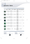
1.2 Accessories
After unpacking the product, make sure the following components are present.
Control board
... 1
Interface cable
... 1 (A cable of 300 mm long)*
Mech FFC
... 1 (With 100-mm-long cable)
* Mini-USB cable is not supplied for USB model.
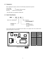
1.3 Model Classification
BD2
―
222
0
RS
J
Model name
Destination
J: Japan (Kanji supported)
U: Universal standard
Mechanism used
0: LT2X20
1: LT2X21
Interface
RS: Serial RS-232C
PA: Parallel IEEE1284
UB: USB
Control board model can be identified by the stamp on the jumper side of the control board.
Stamped designation is shown below.
BD2-222
JP2
JP3
JP5
JP1
JP4
Stamped designation:
2
Model Name
Designation
BD2-2220RSJ
BD2-2220PAJ
BD2-2220UBJ
BD2-2220RSU
BD2-2220PAU
BD2-2220UBU
BD2-2221RSJ
BD2-2221PAJ
BD2-2221UBJ
BD2-2221RSU
BD2-2221PAU
BD2-2221UBU
0RSJ
0PAJ
0UBJ
0RSU
0PAU
0UBU
1RSJ
1PAJ
1UBJ
1RSU
1PAU
1UBU
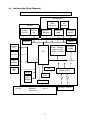
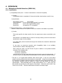
1.4 Configuration (Block Diagram)
BD2-2220/2221 BLOCK DIAGRAM
MECHANISM
HEAD
Thermistor
CUTTER
CUTTER
MOTOR
CUTTER
SW
HEAD UP
SENSOR
PE
SENSOR
PRINTER
HEAD
DRIVER
STEPPING
MOTOR
DRIVER
ERROR
LED
FLASH MEMORY
8Mbit: Foreign
16Mbit: Domestic
CPU
SDRAM
16Mbit
PE LED
PNE
SENSOR
FEED
SW
DC3.3V DC5.0V DC24.0 V
OSC
POWER SUPPLY
DIP SW
RESET
VOLT
SENSOR
Serial Interface
RS-232C
INTERFACE
Parallel Interface
IEEE1284
Centronics
USB Interface
Ver 1.1
3
DC24.0V DC5.0V
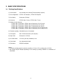
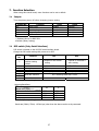
2. BASIC SPECIFICATIONS
2.1 Printing Specifications
1) Print method:
Line thermal print method (Thermal printing system)
2) Dot configuration: LT222X: 432 dots/line, LT232X:576 dots/line
3) Dot density:
8 dots/mm (203 dpi)
4) Print area:
LT222X: Max. 54 mm, LT232X: Max. 72 mm
5) Number of print columns:
LT222X: Max. 36 columns,
LT222X: Max. 48 columns,
LT222X: Max. 54 columns,
LT222X: Max. 18 columns,
LT222X: Max. 27 columns,
LT232X:
LT232X:
LT232X:
LT232X:
LT232X:
Max.
Max.
Max.
Max.
Max.
48
64
72
24
36
columns
columns
columns
columns
columns
(12×24: Font A)
(9×24: Font B)
(8×16: Font C)
(24×24: Kanji Font A)
(16×16: Kanji Font C)
6) Character spacing: Selectable by use of command
7) Print speed:
Max. 1200 dot-lines/sec (150 mm/sec)
8) Paper feed:
Feed pitch: 0.125 mm
9) Line feed width:
4.23 mm (1/6 inch) settable by user
10) Print head:
Line thermal print head
11) Emulation:
ESC/POS compliant
Notes:
• The above printing speed is under the condition of 24.0 V, 25°C, printing duty of 12.5%.
• Print speed may be delayed depending on the setting of printing condition or combination of
commands.
4
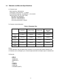
2.2 Character and Barcode Specifications
1) Character type
ANK characters: 96characters
Code pages: 128 characters × 12 pages
International characters: 12 characters × 14 countries
Japanese Kanji: JIS (JIS C6226-1983)
Non-kanji: 577 characters
JIS level 1: 2965 characters
JIS level 2: 3388 characters
(Only when destination is Japan)
2) Character size/configuration
Table 1 Character Size
Font A
12×24
Font B
9×24
Font C
8×16
Kanji A
24×24
Kanji C
16×16
Standard
Double Height
Double Width
W×H (mm)
W×H (mm)
W×H (mm)
Double Height
and Double
Width
W×H (mm)
1.5×3.0
1.5×6.0
3.0×3.0
3.0×6.0
1.13×3.0
1.13×6.0
2.26×3.0
2.26×6.0
1.0×2.0
1.0×4.0
2.0×2.0
2.0×4.0
3.0×3.0
3.0×6.0
6.0×3.0
6.0×6.0
2.0×2.0
2.0×4.0
4.0×2.0
4.0×4.0
Notes:
• Actual character may be smaller than the above as it includes space inside character font.
• Characters can be enlarged up to 8 times height and width in multiple steps of standard size.
3) Barcode
: UPC-A
: UPC-E
: JAN/EAN-8
: JAN/EAN-13
: ITF
: CODE39
: CODE93
: CODE128
: CODABAR (NW-7)
5
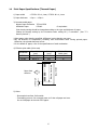
2.3 Print Paper Specifications (Thermal Paper)
1) Paper width
: LT222X: 58 +0,-1mm, LT232X: 80 +0,-1mm
2) Paper thickness
: 60µm ~ 150µm
3) Recommended paper
Nippon Paper Industries
Mitsubishi Paper
TF50-KS-E2D
P220AC
Or equivalent
Print density setting should be changed according to the type and thickness of paper.
Change the density setting by the Customize value setting GS ( E command. (See “7.3
Memory Switch”.)
*When paper other than the specified, difference in print density may occur.
*Pay full attention to temperature, humidity, and environment when storing printed paper.
Otherwise, the printed data may be lost.
*For the details of paper, refer to the specifications of each mechanism.
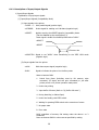
4) Effective print width (Print area)
Left margin
Effective Print
Width (mm)
54
72
Paper Width
Paper feed
direction
Left Margin
(mm)
2±2
4±2
Effective Print Width
LT222X
LT232X
Paper Width
(mm)
58+0,-1
80+0,-1
HHHHHHH……HHHH
Mechanism
5) Other
・Chromophoric surface: Roll outside
・Terminating process: Do not apply paste to fix the roll paper and core.
Do not fold paper at the end of the paper.
6
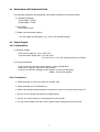
2.4 Mechanism and Peripherals Used
The following mechanism and peripheral units can be connected to this control board.
1) Thermal mechanism
58 mm Paper: LT222X
80 mm Paper: LT232X
2) Auto cutter
ACS-220/230 series
3) Paper near-end sensor (Option)
* For the details of specification, etc., refer to the relevant manual.
2.5 Power Supply
2.5.1 Specifications
1) Operating voltage
Driver power supply Vp:+24.0 VDC ±5%
Logic unit power supply Vdd:+5.0 VDC ±5%
:+3.3 VDC ±5% (*+5.0 VDC internal conversion in board)
2) Current consumption
Driver current Ip: Average current: Approx. 0.46 A (At ANK slide)
Peak current: Approx. 4.9 A (At full dot printing)
Logic unit current Idd: Average current: Approx. 230 mA (At ANK slide)
Approx. 200 mA (At standby)
2.5.2 Precautions
1. When powering on, enter Vp within 100 ms after Vdd.
2. When powering off, turn Vdd after Vp.
3. Before connecting or disconnecting the connector, be sure to turn the printer power off.
4. Be sure to use Vdd and Vp within the specified range.
5. Be sure to use the printer by connecting both Vp and P-GND.
6. For the power supply at Vp side, use the power supply with peak current removed.
7
Cautions
・Using the power supply other than specified, bad effect may occur in printing operation, etc.
・Using the current without removing peak current may result in degradation of printing quality
depending on the printing status or occurrence of low-voltage error.
・Use the power supply that can be turned off easily to prepare for emergencies.
・Power supply with overvoltage protection, overcurrent protection, and various protection
circuits is recommended.
・This control board requires two different supply voltages. Use sufficient care not to make
erroneous wiring or operation. Error in operation may not only break the control board but
also have bad effect on human body or peripheral equipment.
・Though this control board has CN2 that has the same pin allocation as BD2-2880, it is different
in supply voltage. Use sufficient care in handling this control board.
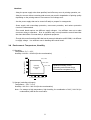
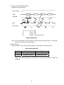
2.6 Environment: Temperature, Humidity
1) Operating
Temperature: 5°C ~ 45°C
Humidity: 10%RH ~ 90%RH (No dew condensation)
Relative humidity (% RH)
34°C, 90%
40°C, 65%
Operating
environment
range
45°C, 50%
Relative humidity (%RH)
Operating environment range
Environment temperature (°C)
Environment temperature (°C)
2) Storage (excluding roll paper)
Temperature: −20°C ~ 60°C
Humidity: 10% RH ~ 90% RH (No dew condensation)
Note: For storage at high temperature, high humidity, the combination of 40°C, 90% RH (no
condensation) shall be the worst value.
8
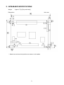
3. APPEARANCE SPECIFICATIONS
Weight
: Approx. 37g (Only main body)
Dimensions
Unit: mm
* Board size and screw hole position are common to all models.
9
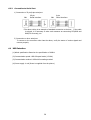
4. Connector Connection
4.1 Interface Connectors
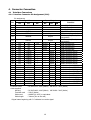
4.1.1 Interface Connector Pin Assignment (CN1)
Pin assignment
Pin
Signal Name
RS
PA
Input/Output
UB
RS
PA
1-2
3-4
5-10
11-16
17
Vdd
GND
Vp
P-GND
nFEED-SW
-
-
-
-
Input
18
nERROR
Output
19
nPEOUT
Output
20
21
22
23
24
25
26
27
28
29
30
31
32
33
34
35
36
37
38
39
40
DTR
TXD
RXD
DSR
N.C
N.C
N.C
N.C
N.C
N.C
N.C
N.C
N.C
N.C
N.C
N.C
N.C
N.C
N.C
N.C
N.C
Connector used
Cable supplied
Housing
Terminal used
Cable used
Cable length
N.C
N.C
N.C
N.C
DATA0
DATA1
DATA2
DATA3
DATA4
DATA5
DATA6
DATA7
nSTROBE
BUSY
nFAULT
nSELECT
PE
nACK
nAUTOFD
nSELECTIN
nRESET
N.C
-
-
-
-
-
-
-
-
-
-
-
-
-
-
-
-
-
-
-
-
Output
Output
Input
Input
-
-
-
-
-
-
-
-
-
-
-
-
-
-
-
-
-
: RS PA 53313-4015 (Molex)
:
:
:
:
-
-
-
-
Input
Input
Input
Input
Input
Input
Input
Input
Input
Output
Output
Output
Output
Output
Input
Input
Input
UB
-
-
-
-
-
-
-
-
-
-
-
-
-
-
-
-
-
-
-
-
-
Function
Circuit PS (+5V)
Circuit GND
Drive PS (+24V)
Drive GND
FEED Switch (Paper feed)
ERROR output (directly
connectable)
PE LED output (directly
connectable)
Serial interface DTR
Serial interface TXD
Serial interface RXD
Serial interface DSR
Parallel interface DATA0
Parallel interface DATA1
Parallel interface DATA2
Parallel interface DATA3
Parallel interface DATA4
Parallel interface DATA5
Parallel interface DATA6
Parallel interface DATA7
Parallel interface nSTROBE
Parallel interface BUSY
Parallel interface nFAULT
Parallel interface nSELECT
Parallel interface PE
Parallel interface nACK
Parallel interface nAUTOFD
Parallel interface nSELECTIN
Parallel interface nRESET
UB 53313-2015 (Molex)
RS PA 51089-4005 (Molex) UB 51089-2005 (Molex)
50212 (Molex)
AWG26 (UL1007) or equivalent
300mm (Cut at the end)
* Signal name beginning with “n” indicates Low active signal.
10
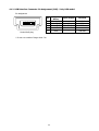
4.1.2 USB Interface Connector Pin Assignment (CN8) * Only USB model
Pin assignment
1
2
3
4
Signal
Name
VBus(+5V)
-Data(D-)
+Data(D+)
N.C
5
GND
Pin
1 2 3 4 5
Series Min B plug
* Do not use a cable of longer than 5 m.
11
Input/Output
Function
-
Input/Output
Input/Output
-
USB PS
USB DUSB D+
Not connectable
-
USB GND
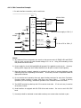
4.1.3 CN1 Connection Example
* For each interface connection, refer to each item.
CN1
1、2
3、4
Vdd
5~10
11~16
Vdd
AC100~240V
+5V
GND
GND Constant
+24V voltage
PS
GND
Vp
P-GND
10kΩ
17
1000pF
FEED SW
100Ω
GND for power supply or CN1-3, 4
SW
+5V
330Ω
18
330Ω
19
ERROR LED
PEOUT LED
5V line of PS or CN1-1, 2
Control Board
Notes:
1) As resistance 330Ω is inserted in the circuit so that current value of ERROR LED and PEOUT
LED is 10 mA, use the LED with forward voltage of 2 V or so. Using LED exceeding 10 mA
may break the control board.
2) Power supply for circuit (Vdd and GND) will operate if it is applied to only one pin. However,
driving power supply (Vp and P-GND) shall be fed to all pins to retain current capacity.
3) Note that though a ceramic capacitor is provided in the circuit to prevent chattering, great
chattering may occur depending on the switch. In this case, the user is requested to take an
appropriate measure.
4) Do not conduct such operation that only paper feeding continues for more than 5 minutes.
Excessive single operation of paper feed motor may cause failure. * In case of printing
operation (12.5% coloring), continuous operation over 5 minutes causes no trouble.
5) The RESET terminal is pulled up with 3.3 kΩ at the circuit side. If it is not in use, it must be
set as Non Connect.
6) Serial interface is equipped with RS-232C driver and receiver.
level.
Be sure to use in RS-232C
7) Unused pin shall be insulated so that cable end may not contact other terminal or part.
12
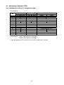
4.2 Mechanism Connector (CN2)
4.2.1 Mechanism Connector Pin Assignment (CN2)
Pin assignment
Pin
1~4
5
6
7
8
9
10
11 ~ 19
20
21
22
23
24
25 ~ 28
Signal Name
Input/Output
LT222X LT232X LT222X LT232X
Vp
N.C
CLK
Output
LAT
Output
N.C
STB2
Output
STB1
Output
TM
GND
TM
Vdd
STB3
STB4
Output
STB2
STB3
Output
DI
Output
Vp
-
Connector used:
Function
LT222X
LT232X
Thermal head PS
N.C
Clock signal for data transmission
Print data latch signal
N.C
Strobe signal 2
Strobe signal 1
Thermistor
GND
Thermistor
Thermal head driver PS
Strobe signal 3
Strobe signal 4
Strobe signal 2
Strobe signal 3
Print data serial output
Thermal head PS
52045-2845 (Molex) or equivalent
52045-2845 (Molex)or equivalent
* Note that assignment of connector pins and control board pins is reversed.
13
4.2.2 FFC-compliant Cable
36.25±0.1
33.75±0.1
1.25±0.05
0.8±0.03
0.3±0.05
Conductive side
Min.4
7 Reinforcing
board
dimension
Unit: mm
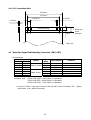
4.3 Head Up, Paper-End Detecting Connector (CN3, CN7)
Pin assignment
Pin
LT2X20 LT2X21
CN3-1
CN3-2
CN3-3
CN3-4
CN3-5
CN3-6
CN3-7
CN7-1
CN7-2
CN3-4
CN3-5
CN3-6
CN3-7
Connector used
Sensor
Head Up sensor
Paper sensor
Signal
Name
Input/Output
HU-A
GND
HU-C
PE-C
PE-K
PE-A
PE-E
Output
-
Input
Output
Input
Output
Input
Function
Head Up signal input
Paper-End signal input
LT2X20 CN3:52045-0745 (Molex) or equivalent
LT2X21 CN3:5597-04CPB (Molex) or equivalent
LT2X21 CN7:53047-0210 (Molex) or equivalent
* In case of LT2X21, 4-pin type is used for CN3 and CN7 is short-circuited by JP4.
open sensor, if any, shall be removed.)
14
(Platen
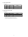
4.4 Motor Connector (CN4)
Pin assignment
Signal
Input/Output
Name
1
MOTOR A+
Output
2
MOTOR BOutput
3
MOTOR AOutput
4
MOTOR B+
Output
Connector used: 53047-0410 (Molex)
Pin
Function
Motor driving signal A+
Motor driving signal BMotor driving signal AMotor driving signal B+
4.5 Auto Cutter Connector (CN5)
Pin assignment
Signal
Input/Output
Name
1
M+
Output
2
MOutput
-
3
GND
4
SW
Input
Connector used: 5267-04A-X (Molex)
Pin
Function
Cutter Motor driving signal M+
Cutter Motor driving signal MGND
Cutter Switch input signal
* Use dedicated cutter (ACS-220/230 series) for cutter.
* If cutter is not used, short the auto cutter feature of JP1.
15
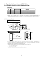
4.6 Paper Near-End Sensor Connector (CN6) * Option
4.6.1 Paper Near-End Sensor Connector Pin Assignment (CN6)
Pin assignment
Signal
Input/Output
Name
1
PNE-A
Output
2
PNE-C
Input
-
3
GND
Connector used: 5267-03A-X (Molex)
Pin
Function
Photo interrupter anode
Photo interrupter collector
Photo interrupter cathode, emitter
* At the time of shipment, pins 2 and 3 are short-circuited by JP5 and paper detection is
disabled (always paper present is defined). In actual use, purchase the above connector.
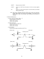
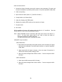
4.6.2 Reference Circuits
Photo interrupter is used.
3.3V
Vcc
330Ω
10kΩ
1
CPU
2
1000
100Ω
68kΩ
Control board
3
Photo interrupter GP2S24
Mechanical switch is used.
1
Sensor
Paper
NC
2
SW
1mm
3
* In the above circuit, reflection type photo interrupter is taken as an example. With the above
sensor, the clearance from paper must be about 1 mm. As electric characteristic varies with
the sensor used, understand the sensor before use.
* Voltage detection range at the control board side (across 2 and 3) is.
0 ~ 0.4V: Paper Present
1V or more: No Paper
This is not warranted in the state other than the above.
16
5. OPERATION PANEL
5.1 Output LED
1) PE LED
ON : Paper-End detection
OFF : Paper Present detection
2) ERROR LED
ON
: Head Up (LT2220/2320 is used), Platen Open (LT2221/2321 is used). Paper-End
Blinking : Hex dump mode, memory switch setting mode, various errors, waiting for macro
execution
OFF
: Normal operation
5.2 Details on Error and LED Indication
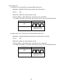
1) Error to recover automatically
(1) Head overheat error
Explanation: For overheat protection, when the temperature of head increases (approx.
65°C or more), the printing is stopped and ERROR LED blinks.
When the temperature of head declines (approx. 60°C or less), the printing
operation is started automatically.
PE LED:
OFF
ERROR LED: Blinks with long illumination at ON
Restore Condition: Automatically restored by temperature decrease
PE LED
ERROR LED
OFF
Blinks with long
illumination at ON
17
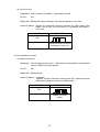
(2) Head Up error (LT2220/2320 is used and MSW3-8 OFF is set.)
Explanation: ERROR LED blinks during printing and when Head Up is set (with Head Up
lever raised).
PE LED:
OFF
ERROR LED: Blinks with long illumination at ON
Restore Condition: Set Head Down (with Head Up lever down).
PE LED
ERROR LED
OFF
Blinks with long
illumination at ON
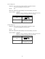
(3) Platen Open Error (LT2221/2321 is used and MSW3-8 OFF is set.)
Explanation: ERROR LED blinks during printing and when Platen Open is set (with Platen
Open lever held down and platen retaining unit opened).
PE LED:
OFF
ERROR LED: Blinks with long illumination at ON
Restore Condition: Close platen (close platen retaining unit and raise the Platen Open
lever).
PE LED
ERROR LED
OFF
Blinks with long
illumination at ON
18
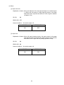
2) Restorable error
(1) Head Up error (LT2220/2320 is used and MSW3-8 ON is set.)
Explanation: ERROR LED blinks during printing and with Head Up.
PE LED:
OFF
ERROR LED: Blinks with long illumination at ON
Restore Condition: After Head Down, clear the error by a command.
* For details of DLE ENQ 1, DLE ENQ 2, and DLE DC4 (fn=8), refer to Command Reference.
PE LED
ERROR LED
OFF
Blinks with long
illumination at ON
(2) Platen Open error (LT2221/2321 is used and MSW3-8 ON is set.)
Explanation: ERROR LED blinks during printing and when platen is opened.
PE LED:
OFF
ERROR LED: Blinks with long illumination at ON
Restore Condition: After Platen Close, clear the error by a command.
* For details of DLE ENQ 1, DLE ENQ 2, and DLE DC4 (fn=8), refer to Command Reference.
PE LED
ERROR LED
OFF
Blinks with long
illumination at ON
19
(3) Cutter lock error
Explanation: Cutter operation is disabled.
PE LED:
Abnormality occurred.
OFF
ERROR LED: ERROR LED repeats blinking 2 times fast and blinking 1 time slow.
Restore Condition: Remove the fault and restore by pressing the FEED switch (with
MSW3-1 set to OFF) or by DLE EMQ 1 or 2 command (with MSW3-1
set to ON).
PE LED
ERROR LED
OFF
Repeats blinking 2 times fast
and blinking 1 time slow.
3) Error impossible to restore
(1) Memory check error
Explanation: CPU self-diagnoses the circuit. When it detects abnormality in external RAM
memory, ERROR LED blinks quickly.
PE LED:
OFF
ERROR LED: Blinking quickly
Restore Condition: Irreparable
However, it can be restored by turning power OFF, replacing external
RAM, and removing the cause of the abnormality.
PE LED
ERROR LED
OFF
ERROR LED blinks
quickly.
20
(2) Low voltage error
Explanation: Occurs when the Vp voltage supplied to the printer is lowered.
If occurred, immediately turn the power OFF.
PE LED:
OFF
ERROR LED: ERROR LED repeats blinking 3 times fast and blinking 1 time slow.
Restore Condition: Irreparable
However, it can be restored by turning the power OFF and then
raising the Vp voltage to the range of DC 16.9 to 27.8 V.
PE LED
ERROR LED
OFF
Repeats blinking 3 times fast
and blinking 1 time slow.
(3) High voltage error
Explanation: Occurs when the Vp voltage supplied to the printer is raised.
If occurred, immediately turn the power OFF.
PE LED:
OFF
ERROR LED: ERROR LED repeats blinking 4 times fast and blinking 1 time slow.
Restore Condition: Irreparable
However, it can be restored by turning the power OFF and then
raising the Vp voltage to the range of DC 16.9 to 27.8 V.
PE LED
ERROR LED
OFF
Repeats blinking 4 times fast
and blinking 1 time slow.
21
4) Others
(1) Paper near-end
Explanation of status: When the diameter of the roll paper deceases to a certain degree
(* differs with the status of using Near-End sensor), the Paper
Near-End sensor responds and allows PE LED to light to indicate
roll paper is low.
PE LED:
ON
ERROR LED: OFF
Restore Condition: Set another paper roll.
PE LED
ERROR LED
ON
OFF
(2) Paper-end
Explanation of status: When roll paper becomes empty, the paper sensor in the paper
path near the print head detects the paper end and causes PE LED
and ERROR LED to light and the printing operation to stop.
PE LED:
ON
ERROR LED: ON
Restore Condition: Set another paper roll.
PE LED
ERROR LED
ON
ON
22
(3) Head Up (when LT2220/2310 is used)
Explanation: When Head Up is set, ERROR LED lights.
PE LED:
OFF
ERROR LED: ON
Restore Condition: Set Head Down.
PE LED
ERROR LED
OFF
ON
(3) Platen Open (when LT2221/2321 is used)
Explanation: When Platen is opened, ERROR LED lights.
PE LED:
OFF
ERROR LED: ON
Restore Condition: Close Platen.
PE LED
ERROR LED
OFF
ON
(4) Waiting for a macro execution
Explanation: The printer is waiting for a macro execution by ESC/POS’s commands.
PE LED:
OFF
ERROR LED: ERROR LED blinks slowly.
Restore Condition: Push the FEED SW.
PE LED
ERROR LED
OFF
Repeats blinking slow.
23
5.3 Feed Switch
Function
• When pressed once, paper feed of one line occurs based on the amount of line feed set by ESC 2
and ESC 3.
However, paper feed is not available in the following cases.
(1) When the FEED switch is set to disable by ESC c 5
(2) When paper-end detector detected no paper
(3) With Head Up.
(LT2220/2310 is used)
(4) With Platen Open (LT2221/2321 is used)
(5) When error occurred
(6) When waiting for macro execution (execution of macro by the FEED switch), pressing the
FEED switch causes the macro to be executed.
• At the time of Cutter Lock error, pressing the FEED switch after removing the cause clears the
error. (Depending on the status of MSW3-1)
24
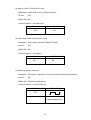
5.3.1 Self-printing
1) Function
Function to enable the printer setting status to be verified by printing
2) Start of self-printing
When the power is turned on with the FEED switch pressed and held in print ready state,
printer status is printed on the roll paper.
Explanation of printed item is as shown below.
(1) Printer type name BD2-2220
(2) ROM version
VX.XXXXXX
(3) Mechanism used
(4) Interface setting
(5) Buffer size
(6) Content of DIP switch setting (Only serial interface)
(7) Jumper settings (Only JP1 to 3. JP4, 5 are not printed.)
(8) Content of memory switch
(9) Font A (20H ~ FFH)
(10) Font B (20H ~ FFH)
(11) Font C(20H ~ FFH)
(12) Kanji Font A 192 characters (Only Kanji specification)
(13) Kanji Font C 192 characters (Only Kanji specification)
(14) Line is fed up to cut position.
3) End of self-printing
Print a specified print pattern and perform resetting after printing for initialization.
25
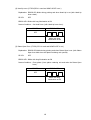
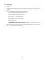
5.3.2 Hexadecimal Dump Printing
1) Function
Prints the data sent from the host in hexadecimal code and the corresponding characters.
2) Starting hexadecimal dump
With paper set and Head Up (or Platen Open), turn the power on while pressing and holding
the FEED switch. Set Head Down (or Platen Close). Then “HEX dump print mode” is printed
on the roll paper followed by the printing of data received thereafter in hexadecimal numbers
and corresponding characters.
Example: When dump printing is executed in Kanji mode.
HEXダンプ印字モード
1B 40 31 32 33 34 35 36 .@123456
37 38 39 30 0A
7890.
Completed
Example: When dump printing is executed in non-Kanji mode.
HEX DUMP PRINT MODE
1B 40 31 32 33 34 35 36 .@123456
37 38 39 30 0A
7890.
Completed
• During hexadecimal dump, command other than Real time command has no function.
• When print data is less than one line, offline factor occurs to print the line.
3) End of hexadecimal dump
• Press the FEED switch consecutively three times. In this case “Completed” is printed and
paper is fed to the cut position and then a reset occurs. Otherwise, turn the power OFF or
perform a reset by the I/F signal.
26
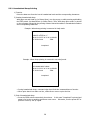
5.3.3 Memory Switch Setting Mode
1) Settable memory switch
MSW1、MSW2、MSW3
2) Starting memory switch setting mode
With paper set and Head Up (or Platen Open), turn the power on while pressing and holding
the FEED switch and then press the FEED switch twice, set Head Down (or Platen Close) to
start the setting mode.
After the setting mode is started, the guidance of setting content and operation method is
printed.
3) Selecting memory switch
By pressing FEED SW shortly (less than 500 ms), the memory switches to be set is selected in
the following order.
In doing so, the status of selected memory switch is printed. However, when f is selected,
the verification of flash memory writing is printed.
(1) MSW1
(2) MSW2
(3) MSW3
(4) Recording / Initialization of the setting
* By pressing the FEED switch long (2s or more) when c to e is selected, setting the
selected memory switch is started. (Goes to the following 4) Setting memory switch.)
* By pressing the FEED switch long when (4) is selected, current memory switch settings are
all written into the flash memory and Reset operation is carried out. (Goes to the
following 5) Terminating memory switch setting mode.)
By pressing the FEED switch long with Head Up (or Platen Open) when (4) is selected, a reset
operation is executed with current memory switch settings discarded and factory setting
restored. (Goes to the following 5) Terminating memory switch setting mode.)
4) Setting memory switch
(1) Print the status of bit which is currently set.
(2) Pressing the FEED switch short (less than 500 ms) causes the selected bit to be inverted.
Here, if the bit is ON, error LED lights.
(3) Pressing the FEED switch long (more than 2s) causes current bit to be saved.
change occurs, the status of the bit is printed.
If any
Setting the following bits is started.
The order of change of bit is shown below.
Bit 0 → Bit 1 →…→ Bit 6 → Bit 7 → Bit 0 →…
(4) The setting is terminated with Head Up (or Platen Open). Then by Head Down, current
status of memory switch is printed and returns to 3) Selecting memory switch.
5) Terminating memory switch setting mode
After setting, the settings are saved and initializing operation (Reset) is carried out and
normal printable condition is restored.
27
6. INTERFACES
6.1 Bidirectional Parallel Interface (IEEE1284)
6.1.1 Specification
1) Compatibility Mode (Host → Printer Communication: Centronics Compliant)
(1) Outline
Compatibility Mode is a standard of Centronics interface that has been used for long.
(2) Specification
Data transfer system:
8 bit parallel
Synchronization:
By the nStrobe signal supplied from outside
Handshake:
By the nAck signal and Busy signal
Signal level:
All signals are TTL compatible.
2) Reverse Mode (Printer → Host Communication)
Transfer of status data from this printer to the host is made in the Nibble or Byte Mode.
(1) Outline
This mode specifies the data transfer from the asynchronous printer controlled by the
host.
Data transfer in the Nibble Mode is carried out through existing control line and data is
transferred in steps of 4 bits (Nibble).
In the Byte Mode, data is transferred through the 8-bit data line treated for bidirectional
transmission.
In any case, as concurrent execution with Compatibility Mode is not available,
communication is made in half duplex mode.
When using this mode, use CN1-38 and 39 pins in addition to the parallel interface
terminal of the interface cable.
CN1-38 pin: nAUTOFD
CN1-39 pin: nSELECTIN
Unless these two pins are used, bidirectional communication cannot be implemented. If
you don’t want to use bidirectional communication, set the terminal to be Non Connect.
* The first “n” of a signal name indicates “LOW” active signal. If any one of the above
signals is missing, bidirectional communication is impossible. Always use twisted pair line
for signal lines of interface while connecting the return side to the signal ground level. All
the interface conditions shall be based on C-MOS level and satisfy the following
characteristics. Rising and falling time of each signal shall be 0.5 µs. Never carry out
data transfer by ignoring the nAck signal or Busy signal. Otherwise, data transfer may
result in loss of data. Interface cable shall be minimum necessary length.
28
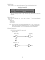
6.1.2 Description of Input/Output Signals
1) Input/Output Signals
Explanation of input/output signals
[1] Input/Output Signals (Compatibility Mode)
(1) Input signals to the printer
・DATA0 ~ 7: 8 bit parallel signal (positive logic)
・nSTROBE:
Strobe signal for reading out 8-bit data (negative logic)
・nRESET:
Applies reset by the nRESET signal in Compatibility Mode.
(Can be disabled by the setting:Msw3-3)
Reset signal is invalid for nSelectIn/1284-Active “HIGH”.
nSELECT
nRESET
150 msec min
・nSELECTIN : Signal to set “HIGH” when transferring to the IEEE 1284 mode
(negative logic)
(2) Output signals from the printer
・nACK:
8-bit data request signal (negative logic)
・BUSY:
Signal to indicate the printer is in the Busy state.
State to become BUSY
1.
Period from Reset (including reset by NV memory write
command, I/F signal, and test print command) or just after
printer power on to printer operation ready state.
2. Under test printing
3. Input buffer full state (Refer to “(4) Buffer full state”.)
4. During Head Up (or Platen Open)
5. Under line feeding with FEED switch
6. Waiting for pressing FEED switch at the execution of macro
7. No paper state
8. Error state
BUSY regardless of memory SW setting under the above 1 to 3
conditions.
Does not become BUSY in other case as specified by setting.
29
・SELECT:
Always non-active (“LOW”).
・nFAULT:
Signal to set “LOW” when the printer is in the error state (negative
logic).
・PE:
Signal to be output with No paper or near-end state (by command
setting) (positive logic)
Note: When using a command followed by FROM writing, printer may temporarily
become BUSY (DTR) at the time of write operation. In this case, as the
printer cannot make any processing, data transmitted may possibly be
discarded.
2) Electrical Characteristics
[1] Input signal level (nStrobe, Data0 ~ 7)
All input signals are C-MOS level.
”HIGH ” level: 2.0V min.
”LOW ” level: 0.8V max.
[2] Output signal level
All output signals are C-MOS level.
”HIGH ” level: 4.4V min.
”LOW ” level: 0.1V max.
[3] I/O conditions
All input/output signals are pulled up with 3.3 kΩ.
[Printer side]
[Host side]
Vcc
Twisted pair wire
3.3KΩ
[Printer side]
[Host side]
Vcc
Twisted pair wire
3.3KΩ
30
3) Timing chart (Compatibility Mode)
Data input and print timing
Power supply
DATA
T2
nSTROBE
T6
T1
T3
T4
BUSY
nACK (Note)
T5
T1,T2,T3
T4
T5
T6
:
:
:
:
0.5 µs MIN
270ns MAX
2.3 µs TYP
1200ms MIN (At power on)
Figure Timing Chart
Note: ACK output position can be changed to ACK in BUSY, ACK while BUSY, or ACK after
BUSY by the setting of customize value.
4) Buffer full state
Buffer full state is when the remaining capacity of input buffer is as shown below.
Table Input Buffer Full
Set Value
Buffer Full
Clear
4K bytes
Remaining 128 bytes
Remaining 256 bytes
45 bytes
Remaining 16 bytes
Remaining 26 bytes
・When the remaining capacity of input buffer is 0 byte, data received is read and
discarded.
31
5) Reverse Mode (Nibble/Byte) mode allows status to be transmitted from the printer.
(Using GS a, DLE EOT n, GS r, of GS I command)
・The transmitting buffer of the printer is 99 bytes. The host must transfer to Reverse
Mode to prevent loss of status. Being in the Reverse Idle state is desired when using
ASB. If this is not possible, always monitor the presence or absence of the transmitting
data from the printer. The ASB not transmitted but accumulated is transmitted
together (OR) with the latest status.
・Identification of information on each status is available.
Identification of Status
Command, Code
Status
GS I
GS r
XON
XOFF
DLE EOT
ASB (1st byte)
ASB (2nd byte)
<0**0****>B
<0**0****>B
<00010001>B
<00010011>B
<0**1**10>B
<0**1**00>B
<0**0****>B
6.1.3 Connection to Parallel Port
1) Connection to 36-pin/25-pin parallel port
CN1
36-pin
Parallel interface
CN1
25-pin
Parallel interface
2) Connection to other parallel port
To connect to the connector other than the above, verify the status of various signals and
connect properly.
32
6.2 RS-232C Serial Interface
6.2.1 Specification
1) Synchronization: Asynchronous
2) Baud rate
2400, 4800, 9600, 19200, 38400, 57600, 115200 bps (User selection)
3) Word configuration
Start bit: 1 bit
Data bit: 7 bits or 8 bits (User selection)
Parity bit: Odd, even, or no parity (User selection)
Stop bit: 1 bit or more
4) Signal polarity
RS-232C
・Mark =Logic ”1” (-3V to-12V)
・Space =Logic ”0” (+3V to +12V)
6.2.2 Description of Input/Output Signals
1) Input/Output Signals
(1) RD
Receive Data
When the host is connected, the unstable TD signal that can occur at the rise (fall) of
host power is defined as a break signal and the data is read and discarded.
(When the host power is turned off, the host may cause unstable state in TD.
of such data shall be avoided.)
Printing
(2) TD
Transmit Data
(3) DSR
When DTR/DSR control is selected, data is transmitted after confirming that this signal
is a space.
When XON/XOFF control is selected, data is transmitted by ignoring DSR.
(4) DTR
Space sets the printer is in the Busy state and mark sets the printer in the Ready state.
Condition to become Busy can be switched by the setting (MSW1-3).
33
・State to become BUSY
1.Period from Reset (including reset by NV memory write command, I/F signal, and
test print command) or just after printer power on to printer operation ready state.
2.Under test printing
3.Input buffer full state (Refer to “(2) Buffer full state”.)
4.During Head Up (or Platen Open)
5.Under line feeding with FEED switch
6.Waiting for pressing FEED switch at the execution of macro
7.No paper state
8.Error state
BUSY regardless of memory SW setting under the above 1 to 3 conditions. Does not
become BUSY in other case as specified by setting.
Note: When XON/XOFF control is selected, mark state occurs only in the state of 1
and 2. In other case, space state is set. Used to know the status of
connection between the printer and host.
The state other than item 3 is defined as offline.
XON/XOFF output condition
・XON transmission
1.Period from Reset (including reset by NV memory write command, I/F signal,
and test print command) or just after printer power on to printer operation
ready state.
2.When input buffer full state is cleared. Does not output if the printer is
offline even memory switch setting is OFF.
3.When the printer changed from offline to online.
full state.
Does not output in buffer
・XOFF transmission
1.When input buffer becomes buffer full state.
2.When the printer changed from online to offline.
full state.
34
Does not output in buffer
2) Buffer full state
Buffer full state is when the remaining capacity of input buffer is as shown below.
Table Input Buffer Full
Set Value
Buffer Full
Clear
4K bytes
Remaining 128 bytes
Remaining 256 bytes
45 bytes
Remaining 16 bytes
Remaining 26 bytes
・When the remaining capacity of input buffer is 0 byte, data received is read and
discarded.
3) Data receive error
When any of the following error occurs, data is printed as “?” or read and discarded
(Msw1-4).
・Parity error
・Framing error
・Overrun error
Note: When a command accompanying flash ROM write is used, the printer may
become BUSY (DTR) temporarily at write operation. In this case, as the printer
cannot process anything, the transmitted data may possibly be discarded.
4) Electrical Characteristics
[1]RS-232C circuit (MAX 232 or equivalent)
Input (RD, DSR)
[Printer side]
[Host side]
Output (DTR, TD)
35
6.2.3
Connection to Serial Port
1) Connection to 25-pin/9-pin serial port
CN1
25-pin
Serial interface
CN1
9-pin
Serial interface
*The above wiring is an example of standard connection to the host. If the cable
is relayed, it is necessary to take such measures as connecting DTR/DSR and
RXD/TXD reversely, etc.
2) Connection to other serial port
To connect to the connector other than the above, verify the status of various signals and
connect properly.
6.3 USB Interface
(1) Whole specification: Based on the specification of USB1.1
(2) Communication speed: USB full-speed mode (12 MHz)
(3) Communication method: USB bulk forwarding method
(4) Power supply: 0 mA (Power is supplied from the printer.)
36
7. Function Selection
When using this control board, some functions can be set to default.
7.1 Jumper
Turn the printer power off before changing jumper setting.
Jumper No.
JP1
JP2
JP3
JP4*
JP5
Function
Auto cutter
Mechanism used
Auto loading
Platen Open sensor
PNE sensor
Open
Enable
●LT2220/2221
●Enable
●Enable
Enable
Short
●Disable
LT2320/2331
Disable
Disable
●Disable
* Disabled (Short) for BD2-2221.
●Default (factory setting)
7.2 DIP switch (Only Serial Interface)
DIP switch is located on the RS-232C serial interface board.
Change the DIP switch setting with power set to OFF.
Switch
No.
1
Function
Communication
condition setting
method
Handshake
Bit length
Parity check
Parity selection
2
3
4
5
6
Baud rate selection
7
8
Reserved
● Default (factory setting)
ON
OFF
● Depend on DIP switch
setting
XON/XOFF
7 bits
With parity
Even parity
Depend on customer’s
value setting.
●
●
●
●
DTR/DSR
8 bits
None
Odd parity
See “Selecting Baud Rate” below.
● Fixed
-
Selecting Baud Rate
Switch No.
Baud Rate (bps)
2400
4800
9600
19200
● Default (factory setting)
6
7
OFF
ON
● OFF
ON
OFF
OFF
● ON
ON
Baud rate (38400, 57600, 115200 bps) other than the above can be set by command.
37
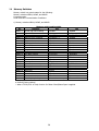
7.3 Memory Switches
Memory switch is a generic name for the following:
Memory switches MSW1, MSW2, and MSW3
Customize value
Serial Interface Communication Conditions
1) Memory switches MSW1, MSW2, and MSW3
No.
MSW1-1
MSW1-2
MSW1-3
MSW1-4
MSW1-5
MSW1-6
MSW1-7
MSW1-8
MSW2-1
MSW2-2
MSW2-3
MSW2-4
MSW2-5
MSW2-6
MSW2-7
MSW2-8
MSW3-1
MSW3-2
MSW3-3
MSW3-4
MSW3-5
MSW3-6
MSW3-7
MSW3-8
Memory switch setting table
Function
OFF
Power ON notice setting
● Enable
Input buffer
● 4K bytes
Busy condition
● Full/Off line
Receive error character
● Character “?”
CR mode
● Disable
Reserved
● Fixed
DSR signal selection
● Disable
Reserved
● Fixed
Reserved
―
Reserved
―
Buffering
● Disable
Full digit printing
● Line feed
Head Down restore *
● Next
Reserved
―
Reserved
● Fixed
Reserved
● Fixed
Auto Cutter recovery
● L/F Enable
Reserved
● Fixed
Parallel Reset
● Reset
Reserved
● Fixed
Reserved
● Fixed
Reserved
● Fixed
Reserved
● Fixed
Head Up in printing *
● Automatic recovery
ON
Disable
45 bytes
Buffer full
Disable
Enable
―
Enable
―
● Fixed
● Fixed
Enable
WaitData
Top
● Fixed
―
―
L/F Disable
―
Ignored
―
―
―
―
Recoverable error
● Default (factory setting)
* When LT2221/2321 is used, function for Platen Close/Platen Open is applied.
38
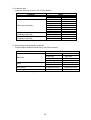
2) Customize value
Customize value can be set by the GS (E command.
Function
Value
1K bytes
64K bytes
Specify the user NV memory capacity
128K bytes
● 192K bytes
70%
75%
80%
85%
90%
95%
Select the print density
● 100%
105%
110%
115%
120%
125%
130%
―
ACK output position
ACK-in-Busy
● ACK-while-Busy
(Verification required)
ACK-after-Busy
―
At Input Buffer Full, BUSY output timing ● 1
2
(Verification required)
3
4
● Default (factory setting)
3) Serial interface communication conditions
Communication conditions can be set by the GS(E command.
Function
Value
2400 bps
● 9600 bps
38400 bps
115200 bps
● None
Even
● DSR/DTR control
7-bit length
Baud rate
Parity
Flow control
Data length
● Default (factory setting)
39
4800 bps
19200 bps
57600 bps
―
Odd
―
XON/XOFF control
● 8-bit length
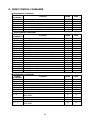
8. PRINT CONTROL COMMANDS
○ Print Control Commands
Control
Function
Command
LF
Printing and paper feed
CR
Back to printing
FF
Printing in page mode and recovery
ESC FF
Printing data in PAGE MODE
ESC J
Printing and feeding paper in minimum pitch
ESC d
Printing and feeding the paper by “n” lines
○ Print Character Commands
Control
Function
Command
CAN
Canceling print data in PAGE MODE
ESC SP
Setting the right spacing of the character
ESC !
Collectively specifying the printing mode
ESC %
Specifying/canceling download character set
ESC &
Defining the download characters
ESC Specifying/canceling underline
ESC ?
Deleting download characters
ESC E
Specifying/canceling emphasis printing
ESC G
Specifying/canceling double strike printing
ESC M
Selection of character fonts
ESC R
Selecting the international character set
ESC V
Specifying/canceling 90°-right-turned characters
ESC t
Selecting the character code table
ESC {
Specifying/canceling the inverted characters
GS
!
Specifying the character size
GS
B
Specifying/canceling the black/white inverted printing
GS
b
Specifying/canceling the smoothing
○ Print Position Commands
Control
Function
Command
HT
Horizontal tab
ESC $
Specifying the absolute positions
ESC D
Setting horizontal tab position
ESC T
Selecting the character printing direction in PAGE MODE
ESC W
Defining the print area in PAGE MODE
ESC \
Specifying the relative position
ESC a
Aligning the characters
Specifying the absolute vertical position of characters in
GS $
PAGE MODE
GS
L
Setting the left margin
GS
W
Setting the print area width
Specifying the relative vertical position of a character in
GS
\
PAGE MODE
40
Mode
S・P
S・P
P
P
S・P
S・P
Mode
P
S・P
S・P
S・P
S・P
S・P
S・P
S・P
S・P
S・P
S・P
S
S・P
S
S・P
S・P
S・P
Mode
S・P
S・P
S・P
P
P
S・P
S
GS P
○
GS P
○
GS P
○
○
○
P
○
S
S・P
○
○
S・P
○
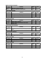
○ Line Feed Span Commands
Control
Function
Command
ESC 2
Specifying 1/6-inch line feed rate
ESC 3
Setting line feed rate of minimum pitch
○ Bit Image Commands
Control
Function
Command
ESC *
Specifying the bit image mode
GS *
Defining the download bit image
GS
/
Printing the downloaded bit image
GS
v 0
Printing of raster bit image
○ Status Commands
Control
Function
Command
DLE EOT
Sending status in real-time
GS
a
Enabling/disabling ASB (Automatic Status Back)
GS
r
Sending status
○ Paper Detecting Commands
Control
Function
Command
Selecting the Paper Sensor valid for Paper-end signal
ESC c 3
output
ESC c 4
Selecting the Paper Near-end Sensor valid for print stop
○ Panel Switch Commands
Control
Function
Command
ESC c 5
Enabling/disabling the panel switches
○ Macro Commands
Control
Function
Command
GS
:
Starting/ending macro definition
GS
^
Executing the macro
○ Cutter Commands
Control
Function
Command
ESC i
Cutting the paper partially
ESC m
Cutting the paper partially
GS
V
Cutting the paper
41
Mode
GS P
S・P
S・P
○
Mode
GS P
S・P
S・P
S・P
S
Mode
GS P
S・P
S・P
S・P
Mode
GS P
S・P
S・P
Mode
GS P
S・P
Mode
GS P
S・P
S・P
Mode
GS P
S・P
S・P
S・P
○
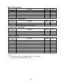
○ Bar Code Commands
Control
Function
Command
GS
H
Selecting of printing position of HRI characters
GS
f
Selecting the font of HRI characters
GS
h
Specifying the height of the bar code
GS
k
Printing the bar code
GS
w
Specifying the horizontal size (magnification) of bar code
○ Commands for Flash Memory
Control
Function
Command
FS
p
Printing the bit image in flash memory
FS
q
Defining the bit image in flash memory
○ Printer Setting Commands
Control
Function
Command
GS ( E
User-defined command
GS ( K
Selecting print control method
GS ( M
Customizing the printer
○ Other Commands
Control
Function
Command
DLE ENQ
Real-time request to printer
DLE DC4
Clearing buffer
ESC =
Data input control
ESC @
Initializing the printer
ESC L
Selecting PAGE MODE
ESC S
Selecting STANDARD MODE
GS
( A
Execution of test printing
GS
I
Sending the printer ID
GS
P
Specifying the basic calculation pitch
Notes:
• In the Mode column: S = STANDARD MODE, P = PAGE MODE.
• { = shows the command affected by GS P.
42
Mode
GS P
S・P
S・P
S・P
S・P
S・P
Mode
GS P
S
S
Mode
GS P
S
S
S
Mode
S・P
S・P
S・P
S・P
S
P
S
S・P
S・P
GS P
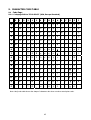
9. CHARACTER CODE TABLE
9.1 Code Page
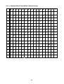
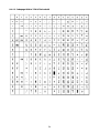
9.1.1 Codepage 00H to 7FH & PC437 (USA, Europe Standard)
3
4
5
6
7
8
9
A
B
C
D
E
0
@
P
`
p
Ç
É
á
░
└
╨
α ≡
!
1
A
Q
a
q
ü
æ
í
▒
┴
╤
β ±
"
2
B
R
b
r
é
Æ
ó
▓
┬
╥
Γ ≧
XOFF
#
3
C
S
c
s
â
ô
ú
│ ├
╙
π ≦
DC4
$
4
D
T
d
t
ä
ö
ñ
┤ ─
╘
∑
⌠
%
5
E
U
e
u
à
ò
Ñ
╡
┼
╒
σ
⌡
6
&
6
F
V
f
v
å
û
a
╢
╞
╓
μ ÷
7
'
7
G
W
g
w
ç
ù
o
╖
╟
╫
τ
≈
(
8
H
X
h
x
ê
ÿ
¿
╕
╚
╪
Φ
。
0
0
1
NUL
DLE
1
XON
2
3
4
EOT
5
ENQ
8
CAN
2
F
9
HT
)
9
I
Y
i
y
ë
Ö
⌐
╣
╔
┘ θ
∙
A
LF
*
:
J
Z
j
z
è
Ü
¬
║
╩
┌ Ω
∙
ESC
+
;
K
[
k
{
ï
¢
½
╗
╦
█
δ √
B
C
FF
FS
,
<
L
\
l
|
î
£
¼
╝
╠
▃
∞
ⁿ
D
CR
GS
-
=
M
]
m
}
ì
¥
¡
╜
═
▌
φ
²
RS
.
>
N
^
n
~
Ä
Pt
«
╛
╬
▐
∈
■
/
?
O
_
o
・
Å
ƒ
»
┐
╧
▄
∩
E
F
Note: Kanji code table shows the shape of characters but does not show actual print result.
43
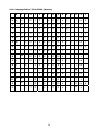
9.1.2 Codepage 00H to 7FH & Katakana
3
4
5
6
7
8
9
D
E
F
0
@
P
`
p
▁
┴ SP - タ ミ
═
×
!
1
A
Q
a
q
▂
┬
ア チ ム
╞
円
"
2
B
R
b
r
▃
┤ ┌ イ ツ メ
╪
年
XOFF
#
3
C
S
c
s
▅
├ ┘ ウ テ モ
╡
月
DC4
$
4
D
T
d
t
▆
─ 、 エ ト ヤ
◢
日
%
5
E
U
e
u
▇
_
オ ナ ユ
◣
時
6
&
6
F
V
f
v
█
| ヲ カ ニ ヨ
◥
分
7
'
7
G
W
g
w
▉
▕
ァ キ ヌ ラ
◤
秒
(
8
H
X
h
x
▏
┌ ィ ク ネ リ
♠
〒
0
0
1
NUL
DLE
1
XON
2
3
4
EOT
5
ENQ
8
CAN
2
A
º
・
B
C
9
HT
)
9
I
Y
i
y
▎
┐ ゥ ケ ノ ル
♥
市
A
LF
*
:
J
Z
j
z
▍
└ ェ コ ハ レ
♦
区
ESC
+
;
K
[
k
{
▌
┘ ォ サ ヒ ロ
♣
町
B
C
FF
FS
,
<
L
\
l
|
▋
╭
ャ シ フ ワ ● 村
D
CR
GS
-
=
M
]
m
}
▋
╮
ュ ス ヘ ン ○ 人
RS
.
>
N
^
n
~
▊
╰
ョ セ ホ “
╱
▒
/
?
O
_
o
・
+
╯
ッ ソ マ ゜
╲
SP
E
F
44
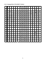
9.1.3 Codepage 00H to 7FH & PC850/858 (Multilingual)
3
4
5
6
7
8
9
A
B
C
D
E
F
0
@
P
`
p
Ç
É
á
░
└
ð
Ó
―
!
1
A
Q
a
q
ü
æ
í
▒
┴
Ð
β ±
"
2
B
R
b
r
é
Æ
ó
▓
┬
Ê
Ô
=
XOFF
#
3
C
S
c
s
â
ô
ú
│ ├
Ë
Ò
¾
DC4
$
4
D
T
d
t
ä
ö
ñ
┤ ─
È
õ
¶
%
5
E
U
e
u
à
ò
Ñ
Á
┼
€
Õ
§
6
&
6
F
V
f
v
å
û
a
Â
ã
Í
μ ÷
7
'
7
G
W
g
w
ç
ù
o
À
Ã
Î
þ
,
(
8
H
X
h
x
ê
ÿ
¿
©
╚
Ï
Þ
°
0
0
1
NUL
DLE
1
XON
2
3
4
EOT
5
ENQ
8
CAN
2
9
HT
)
9
I
Y
i
y
ë
Ö
®
╣
╔
┘
Ú
¨
A
LF
*
:
J
Z
j
z
è
Ü
¬
║
╩
┌
Û
∙
ESC
+
;
K
[
k
{
ï
ø
½
╗
╦
█
Ù
¹
B
C
FF
FS
,
<
L
\
l
|
î
£
¼
╝
╠
▃
ý
³
D
CR
GS
-
=
M
]
m
}
ì
Ø
¡
¢
═
¦
Ý
₂
RS
.
>
N
^
n
~
Ä
×
«
\
╬
Ì
¯
■
/
?
O
_
o
・
Å
ƒ
»
┐
¤
▄
′
E
F
45
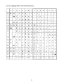
9.1.4 Codepage 00H to 7FH & PC860 (Portuguese)
3
4
5
6
7
8
9
A
B
C
D
E
0
@
P
`
p
Ç
É
á
░
└
╨
α ≡
!
1
A
Q
a
q
ü
À
í
▒
┴
╤
β ±
"
2
B
R
b
r
é
È
ó
▓
┬
╥
Γ ≧
XOF
F
#
3
C
S
c
s
â
ô
ú
│ ├
╙
π ≦
DC4
$
4
D
T
d
t
ã
õ
ñ
┤ ─
╘
∑
⌠
%
5
E
U
e
u
à
ò
Ñ
╡
┼
╒
σ
⌡
6
&
6
F
V
f
v
Á
Ú
a
╢
╞
╓
μ ÷
7
'
7
G
W
g
w
ç
ù
o
╖
╟
╫
τ
(
8
H
X
h
x
ê
Ì
¿
╕
╚
╪
Φ °
0
0
1
NUL
DLE
1
XON
2
3
4
EOT
5
ENQ
8
CAN
2
F
≈
9
HT
)
9
I
Y
i
y
Ê
Õ
Ò
╣
╔
┘ θ
A
LF
*
:
J
Z
j
z
è
Ü
¬
║
╩
┌ Ω
ESC
+
;
K
[
k
{
Í
¢
½
╗
╦
█
δ √
B
∙
C
FF
FS
,
<
L
\
l
|
Ô
£
¼
╝
╠
▃
∞
ⁿ
D
CR
GS
-
=
M
]
m
}
ì
Ù
¡
╜
═
▌
∅
₂
RS
.
>
N
^
n
~
Ã
Pt
«
╛
╬
▐
∈
■
/
?
O
_
o
・
Â
Ó
»
┐
╧
▄
∩
E
F
46
9.1.5 Codepage 00H to 7FH & PC863 (Canadian-French)
3
4
5
6
7
8
9
A
B
C
D
E
0
@
P
`
p
Ç
É
¦
░
└
╨
α ≡
!
1
A
Q
a
q
ü
È
´
▒
┴
╤
β ±
"
2
B
R
b
r
é
Ê
ô
▓
┬
╥
Γ ≧
XOFF
#
3
C
S
c
s
â
ô
ú
│ ├
╙
π ≦
DC4
$
4
D
T
d
t
Â
Ë
¨ ┤ ─
╘
∑
⌠
%
5
E
U
e
u
à
Ï
ゝ
╡
┼
╒
σ
⌡
6
&
6
F
V
f
v
¶
û
³
╢
╞
╓
μ ÷
7
'
7
G
W
g
w
ç
ù
-
╖
╟
╫
τ
≈
(
8
H
X
h
x
ê
¤
Î
╕
╚
╪
Φ
。
0
0
1
NUL
DLE
1
XON
2
3
4
EOT
5
ENQ
8
CAN
2
F
9
HT
)
9
I
Y
i
y
ë
Ô
⌐
╣
╔
┘ θ
A
LF
*
:
J
Z
j
z
è
Ü
¬
║
╩
┌ Ω
ESC
+
;
K
[
k
{
Ï
¢
½
╗
╦
█
δ √
B
∙
C
FF
FS
,
<
L
\
l
|
Î
£
¼
╝
╠
▃
∞
ⁿ
D
CR
GS
-
=
M
]
m
}
=
Ù
¾
╜
═
▌
∅
²
RS
.
>
N
^
n
~
À
Û
«
╛
╬
▐
∈
■
/
?
O
_
o
・
§
ƒ
»
┐
╧
▄
∩
E
F
47
9.1.6 Codepage 00H to 7FH & PC865 (Nordic)
3
4
5
6
7
8
9
A
B
C
D
E
0
@
P
`
p
Ç
É
á
░
└
╨
α ≡
!
1
A
Q
a
q
ü
æ
í
▒
┴
╤
β ±
"
2
B
R
b
r
é
Æ
ó
▓
┬
╥
Γ ≧
XOFF
#
3
C
S
c
s
â
ô
ú
│ ├
╙
π ≦
DC4
$
4
D
T
d
t
ä
ö
ñ
┤ ─
╘
∑
⌠
%
5
E
U
e
u
à
ò
Ñ
╡
┼
╒
σ
⌡
6
&
6
F
V
f
v
å
û
a
╢
╞
╓
μ ÷
7
'
7
G
W
g
w
ç
ù
o
╖
╟
╫
τ
≈
(
8
H
X
h
x
ê
ÿ
¿
╕
╚
╪
Φ
。
0
0
1
NUL
DLE
1
XON
2
3
4
EOT
5
ENQ
8
CAN
2
F
9
HT
)
9
I
Y
i
y
ë
Ö
⌐
╣
╔
┘ θ
A
LF
*
:
J
Z
j
z
è
Ü
¬
║
╩
┌ Ω
ESC
+
;
K
[
k
{
Ï
ø
½
╗
╦
█
δ √
B
∙
C
FF
FS
,
<
L
\
l
|
Î
£
¼
╝
╠
▃
∞
ⁿ
D
CR
GS
-
=
M
]
m
}
Ì
Ø
¡
╜
═
▌
∅
₂
RS
.
>
N
^
n
~
Ä
Pt
«
╛
╬
▐
∈
■
/
?
O
_
o
・
Å
ƒ
¤
┐
╧
▄
∩
E
F
48
9.1.7 Codepage 00H to 7FH & PC852 (Eastern Europe)
3
4
5
6
7
8
9
A
B
C
D
E
F
0
@
P
`
p
Ç
É
á
░
└
đ
ó
-
!
1
A
Q
a
q
ü
Ĺ
í
▒
┴
Đ
β ”
"
2
B
R
b
r
é
í
ó
▓
┬
Ď
Ó
、
XOFF
#
3
C
S
c
s
â
ú
ú
│ ├
Ë
Ń
ˇ
DC4
$
4
D
T
d
t
ä
ö
Ą
┤ ─
ď
ń
˘
%
5
E
U
e
u
ů
Ľ
ą
Á
┼
Ň
ň
§
6
&
6
F
V
f
v
ć
Ĭ
Ž
Â
Ă
Í
Š
÷
7
'
7
G
W
g
w
ç
Ś
ž
Ě
ă
î
š
ゝ
(
8
H
X
h
x
ł
ś
Ę
Ş
╚
ĕ
Ŕ
゚
ę
╣
╔
┘
Ú
¨
║
╩
┌
ŕ
∙
ź
╗
╦
█
Ű
ű
Č
╝
╠
▃
ý
Ř
0
0
1
NUL
DLE
1
XON
2
3
4
EOT
5
ENQ
8
CAN
2
9
HT
)
9
I
Y
i
y
ë
Ö
A
LF
*
:
J
Z
j
z
Ő
Ü
ESC
+
;
K
[
k
{
ő
Ť
B
C
FF
FS
,
<
L
\
l
|
î
D
CR
GS
-
=
M
]
m
}
Ź
Ł
ş
Ż
═
Ţ
Ý
ř
RS
.
>
N
^
n
~
Ä
×
«
ż
╬
Ů
ţ
■
/
?
O
_
o
・
Ć
č
»
┐
¤
▀
´
E
F
49
9.1.8 Codepage 00H to 7FH & PC866 (Russian)
3
4
5
6
7
8
A
B
C
D
E
F
0
@
P
`
p
Α Р а
░
└
╨
р
Ë
!
1
A
Q
a
q
Б С б
▒
┴
╤
с
ë
"
2
B
R
b
r
В Т в
▓
┬
╥
т
Є
XOFF
#
3
C
S
c
s
Г У г │ ├
╙
у
є
DC4
$
4
D
T
d
t
Д Ф д ┤ ─
╘
ф
Ї
%
5
E
U
e
u
Е Х е
╡
┼
╒
ц
ї
6
&
6
F
V
f
v
Ж Ц ж
╢
╞
╓
ц
ў
7
'
7
G
W
g
w
З Ч з
╖
╟
╫
ч
(
8
H
X
h
x
И Ш и
╕
╚
╪
х
゚
0
0
1
NUL
DLE
1
XON
2
3
4
EOT
5
ENQ
8
CAN
2
9
9
HT
)
9
I
Y
i
y
Й Щ й
╣
╔
┘ ш
・
A
LF
*
:
J
Z
j
z
К Ъ к
║
╩
┌ щ
∙
ESC
+
;
K
[
k
{
Л Ы л
╗
╦
█
ъ √
B
C
FF
FS
,
<
L
\
l
|
М Ь м
╝
╠
▃
ы
No
.
D
CR
GS
-
=
M
]
m
}
Н Э н
╜
═
Ţ
э
¤
RS
.
>
N
^
n
~
О Ю о
╛
╬
Ů
ю
■
/
?
O
_
o
・
П Я п ┐
╧
▀
я
E
F
50
9.1.9 Codepage 00H to 7FH & PC857 (Turkish)
3
4
5
6
7
8
9
A
B
C
D
E
F
0
@
P
`
p
Ç
É
á
░
└
o
ó
―
!
1
A
Q
a
q
ü
æ
í
▒
┴
a
β ±
"
2
B
R
b
r
é
Æ
ó
▓
┬
Ê
ô
XOFF
#
3
C
S
c
s
â
ô
ú
│ ├
Ë
ò
¾
DC4
$
4
D
T
d
t
à
ö
ñ
┤ ─
È
õ
¶
%
5
E
U
e
u
ä
ò
Ñ
Á
┼
Õ
§
6
&
6
F
V
f
v
å
û
Ĝ
Â
ã
Í
μ ÷
7
'
7
G
W
g
w
ç
ù
ĝ
À
Ã
Î
ゝ
(
8
H
X
h
x
ê
Í
¿
©
╚
Ï
×
゚
0
0
1
NUL
DLE
1
XON
2
3
4
EOT
5
ENQ
8
CAN
2
9
HT
)
9
I
Y
i
y
ë
Ö
®
╣
╔
┘
Ú
¨
A
LF
*
:
J
Z
j
z
è
Ü
¬
║
╩
┌
Û
.
ESC
+
;
K
[
k
{
ï
ø
½
╗
╦
█
Ù
¹
B
C
FF
FS
,
<
L
\
l
|
î
£
¼
╝
╠
▃
Ì
³
D
CR
GS
-
=
M
]
m
}
I
Ø
¡
¢
═
¦
ÿ
²
RS
.
>
N
^
n
~
Ä
Ş
«
¥
╬
Ì
-
■
/
?
O
_
o
・
Å
ş
»
┐
¤
▀
´ SP
E
F
51
9.1.10 Codepage 00H to 7FH & PC864 (Arabic)
52
9.1.11 Codepage 00H to 7FH & WPC1252
3
4
5
6
7
8
0
@
P
`
p
€
!
1
A
Q
a
q
"
2
B
R
b
r
XOFF
#
3
C
S
c
DC4
$
4
D
T
%
5
E
6
&
6
7
'
0
0
1
NUL
DLE
1
XON
2
3
4
EOT
5
ENQ
8
CAN
2
9
A
B
C
D
E
F
°
À
Ð
à
ð
‘
¡
±
Á
Ñ
á
ñ
¸
’
¢
²
Â
Ò
â
ò
s
ƒ
“
£
³
Ã
Ó
ã
ó
d
t
,, ”
¤
´
Ä
Ô
ä
Ô
U
e
u
...
‧
¥
µ
Å
Õ
å
Õ
F
V
f
v
† ‐
¦
¶
Æ
Ö
æ
ö
7
G
W
g
w
‡
‒
§
·
Ç
×
ç
÷
(
8
H
X
h
x
ˆ
~
¨
¸
È
Ø
è
ø
9
HT
)
9
I
Y
i
y
‰
™
©
¹
É
Ù
é
ù
A
LF
*
:
J
Z
j
z
Š
š
ª
º
Ê
Ú
ê
ú
ESC
+
;
K
[
k
{
‹
›
«
»
Ë
Û
ë
û
Œ
œ
¬
¼
Ì
Ü
ì
ü
½
Í
Ý
í
ý
ž
®
¾
Î
Þ
î
þ
Ÿ
¯
¿
Ï
ß
ï
ÿ
B
C
FF
FS
,
<
L
\
l
|
D
CR
GS
-
=
M
]
m
}
RS
.
>
N
^
n
~
/
?
O
_
o
・
E
F
53
Ž
9.1.12 Codepage 00H to 7FH & Thaicode18
54
9.2 International Character Code Table
Country
0
USA
1
France
2
Germany
3
UK
4
Denmark I
5
Sweden
6
Italy
7
23
24
40
5B
5C 5D 5E
60
7B
7C 7D
7E
# $ @
[
╲
]
^
'
{
|
}
~
# $
à
°
ç
§
^
'
é
ù
È
¨
# $ §
Ä
Ö
Ü
^
'
ä
ö
ü
β
£
$ @
[
╲
]
^
'
{
|
}
~
# $ @
Æ
Ø
Å
^
'
æ
ø
å
~
#
Ä
Ö
Å
Ü
é
ä
ö
å
ü
# $ @ °
╲
é
^
ù
à
ò
è
ì
Spain I
Pt $ @
¡
Ñ
¿
^
'
¨
ñ
}
~
8
Japan
# $ @
[
¥
]
^
'
{
|
}
~
9
Norway
#
10
¤
É
¤
É
Æ
Ø
Å
Ü
é
æ
ø
å
ü
Denmark II
# $
É
Æ
Ø
Å
Ü
é
æ
ø
å
ü
11
Spain II
# $
á
¡
Ñ
¿
é
'
ì
ñ
ó
ú
12
Latin America
# $
á
¡
Ñ
¿
é
ü
ì
ñ
ó
ú
13
Korea
# $ @
[
₩
]
^
'
{
|
}
~
55