1
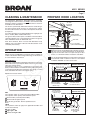
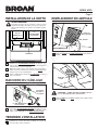
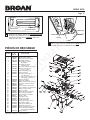
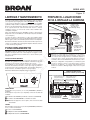
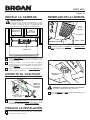
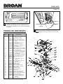
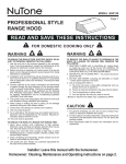
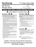
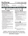
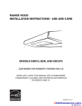
APE1 SERIES
Page 1
PROFESSIONAL STYLE
RANGE HOOD
READ AND SAVE THESE INSTRUCTIONS
FOR DOMESTIC COOKING ONLY
WARNING
WARNING
TO REDUCE THE RISK OF FIRE, ELECTRIC SHOCK, OR INJURY TO PERSONS, OBSERVE THE FOLLOWING:
1. Use this unit only in the manner intended by the manufacturer.Ifyouhavequestions,contactthemanufactureratthe
addressortelephonenumberlistedinthewarranty.
2. Beforeservicingorcleaningunit,switchpoweroffatservice
panel.Lockortagservicepaneltopreventpowerfrombeing
switchedonaccidentally.
3. Installationworkandelectricalwiring(includingswitchlocation) must be done by a qualified person(s) in accordance
withallapplicablecodesandstandards,includingfire-rated
construction.
4. Providesufficientairforpropercombustionandexhaustingof
gasesthroughtheflue(chimney)offuelburningequipment
to prevent backdrafting. Follow the combustion equipment
standardssuchasthosepublishedbytheNationalFireProtectionAssociation(NFPA),theAmericanSocietyforHeating,RefrigerationandAirConditioningEngineers(ASHRAE),
andlocalcodes.
5. Thisproductmayhavesharpedges.Becarefultoavoidcuts
andabrasionsduringinstallationandcleaning.
6. When cutting or drilling into wall or ceiling, do not damage
electricalwiringandotherhiddenutilities.
7. Ductedfansmustalwaysbeventedtotheoutdoors.
8. Useonlymetalductwork.
9. Asanalternative,thisproductmaybeinstalledwiththeULapproved cord kit designated for the product, following instructionspackedwiththecordkit.
10.Thisunitmustbegrounded.
TO REDUCE THE RISK OF INJURY TO PERSONS IN THE
EVENT OF A RANGE TOP GREASE FIRE, OBSERVE THE
FOLLOWING:*
1. SMOTHER FLAMES with a close-fitting lid, cookie sheet,
or metal tray, then turn off the burner. BE CAREFUL TO
PREVENTBURNS.Iftheflamesdonotgooutimmediately,
EVACUATEANDCALLTHEFIREDEPARTMENT.
2. NEVERPICKUPAFLAMINGPAN—Youmaybeburnedor
spreadthefire.
3. DONOTUSEWATER,includingwetdishclothsortowels-
violentsteamexplosionwillresult.
4. UseanextinguisherONLYif:
A. You know you have a ClassABC extinguisher and you
alreadyknowhowtooperateit.
B. Thefireissmallandcontainedintheareawhereitstarted.
C. Thefiredepartmentisbeingcalled.
D. Youcanfightthefirewithyourbacktoanexit.
*Basedon“KitchenFireSafetyTips”publishedbyNFPA.
TO REDUCE THE RISK OF A RANGE TOP GREASE FIRE:
1. Never leave surface units unattended at high settings.
Boiloverscausesmokingandgreasyspilloversthatmayignite.Heatoilsslowlyonlowormediumsettings.
2. Always turn hood ON when cooking at high heat or when
flambeing food (i.e. Crepes Suzette, Cherries Jubilee, PeppercornBeefFlambe).
3. Clean ventilating fans frequently. Grease should not be allowedtoaccumulateonfanorfilter.
4. Use proper pan size.Always use cookware appropriate for
thesizeofthesurfaceelement.
CAUTION
1. Forindooruseonly.
2. Forgeneralventilatinguseonly.Donotusetoexhausthazardousorexplosivematerialsandvapors.
3. Forbestcaptureofcookingimpurities,rangehoodshouldbe
mountedsothatthebottomofthehoodis18”-24”abovethe
cookingsurface.
4. Read specification label on product for information and requirements.
NOTEThese instructions are for ducted installations only.
Ifhoodistobeinstallednon-ducted:
Purchaseanon-ductedfilterkitfromyourlocaldistributoror
retailer.Followinstructionsincludedwiththenon-ductedkit.
Conversiontonon-ductednullifiesENERGYSTAR®qualification.
Registeryourproductonlineat:www.broan.com/register
Installer: Leave this manual with the homeowner.
Homeowner: Cleaning, Maintenance and Operating instructions on page 2.
APE1 SERIES
Page 2
CLEANING & MAINTENANCE
PREPARE HOOD LOCATION
Forperformance,appearance,andhealthreasons,cleanfilter,
fanandgrease-ladensurfaces.Useonlyacleanclothandmild
detergentsolutiononstainlessandpaintedsurfaces.Cleanallmetalfiltersinthedishwasher.
ROOF CAP
Themotorispermanentlylubricatedandneverneedsoiling.If
themotorbearingsmakeexcessiveorunusualnoise,replace
themotorwiththeexactservicemotor.Theimpellershouldalso
bereplaced.
SOFFIT
Use120V,42WfluorescentlampGX24Q-4.Fornightlight,use
4W,C-7bulbs.(Bulbsincludedwithhood.)
WALL CAP
HOOD
Note: Some minerals, when in contact with dishwasher soap
additives,maycausefilterstodiscolor.Thisdiscolorationisnot
coveredbythewarranty.
AlwaysturnthehoodONbeforecookinginordertoestablishan
airflowinthekitchen.Afterturningofftherange,letthehoodrun
forafewminutestocleartheair.
HEAT SENTRY™
ThehoodisequippedwithaHeatSentry™thermostat.Thissafety
devicewillturnonorspeeduptheblowerifitsensesexcessheat
abovethecookingsurface.
Iftheblowerisnoton,orifitisrunningatlowspeed,theHeat
Sentry™willoverridethenormalblowercontrolandruntheblower
onthehighspeed.Whenthetemperatureleveldropstonormal
levels,theblowerwillreturntoitsoriginalsetting.
HOUSE WIRING
(Top or Back of hood)
CABINET
The grease filters, bottom panel, and blower wheel should be
cleanedfrequently.Useawarmdetergentsolution.Thegrease
filtersandblowerwheelaredishwashersafe.
OPERATION
1
Determinewhetherhoodwilldischargeverticallyorhorizontally.Forverticalorhorizontaldischarge,runductworkbetweenthehoodlocationandaroofcaporwallcap.Forbest
results,useaminimumnumberoftransitionsandelbows.
2
Usetheproperdiagrambelow,forplacementofductwork
andelectricalcutoutincabinetorwall.Foranon-ducted
installation,DONOTcutaductaccesshole.
1315/16" (30" hood)
1615/16" (36" hood)
CABINET FRONT
CABINET
6 8" BOTTOM
6¼"
10
FAN
5/
8"
WOOD SHIMS
(recessed-bottom
cabinets only)
OFF
3¼” X 10”
VERTICAL DUCTING
HOOD MOUNTING SCREWS (4)
7/
FAN
3¼" X 10" DUCT
(For horizontal discharge)
18" - 24" ABOVE
COOKING SURFACE
Operatethehoodasfollows:
ON
3¼" X 10"
(For vertical
discharge)
1315/16" (30" hood)
1615/16" (36" hood)
7
6¼"
1/
11/2"
2"
97/8"
VERTICAL DUCT
ACCESS HOLE
CENTER
LINE
9"
ELECTRICAL
ACCESS HOLE
(in cabinet bottom)
LIGHT
FAN
The2-positionswitch(incenter)turnsblowerONandOFF.
The5-positionswitch(atleft)controlsblowerspeed.
BlowerisOFF(secondaryblowerOFF).
BlowerisONathighestspeed.
Asdotsgetsmaller-blowerspeeddecreases.
LIGHT
This 3-position switch (at right) turns lights ON and OFF and
controlstheirintensity.
LightsareOFF.
NightLightisON.
FluorescentLightisON.
WOOD SHIMS
(recessed-bottom
cabinets only)
3¼” X 10”
VERTICAL DUCTING
CABINET FRONT
3/
4"
1/
8"
37/8"
CABINET
BOTTOM
HORIZONTAL DUCT
ACCESS HOLE
6¼"
6¼"
71/2"
1315/16" (30" hood)
1315/16" (30" hood)
1615/16" (36" hood)
1615/16" (36" hood)
HOOD
ELECTRICAL
MOUNTING
CENTER
ACCESS HOLE
SCREWS (4)
LINE
(in wall)
APE1 SERIES
Page 3
PREPARE THE HOOD
DAMPER/
DUCT
CONNECTOR
BOTTOM
COVER
VERTICALDUCT
KNOCKOUT
ALUMINUM
FILTERS
HORIZONTALDUCT
KNOCKOUT
WIRING
COVER
3
RemoveVertical Duct KnockoutorHorizontal Duct
KnockoutandattachDamper / Duct Connectorwith
two(2)screws(supplied).
5
Remove the Aluminum Filters, Bottom Cover, and
Wiring Coverfromthehood.
INSTALL THE HOOD
WARNING
VERTICALDISCHARGEPOSITION
BLOWER
MOUNTING
ROD(2)
Toreducetheriskofelectricalshock,switchpoweroff
atservicepanel.Lockortagservicepaneltoprevent powerfrombeingswitchedonaccidentally.
MOUNTING
SCREWS(4)
BLOWER
HOUSE
POWER
CABLE
KNURLEDNUT(2)
HORIZONTALDISCHARGEPOSITION
BLOWER
MOUNTING
ROD(2)
DUCTWORK
BLOWER
KNURLEDNUT(2)
4
BlowerisshippedinVertical Discharge Position.
TochangeblowertoHorizontal Discharge Position:
Remove Knurled Nuts from Blower Mounting Rods.
Disengagemountingrodsfromblowerandrotateblower
to horizontal discharge position. Re-engage mounting
rodsandtightenblowerinplacewithknurlednuts.
6
Run House Power Cable between service panel and
hoodlocation.Attachpowercabletohoodusingappropriateconnector.
7
Hold the hood in position under the cabinet. Make sure
the damper / duct connector enters the Ductwork and
thatthedamperopensandclosesfreely.
8
Tightenthefour(4)Mounting Screwscompletelytosecurethehoodtothecabinet.
APE1 SERIES
Page 4
CONNECT THE WIRING
LAMP
GREEN
GROUND
SCREW
LAMP
BASE
HOUSE
POWER
CABLE
HE0059
9
Connect House Power Cable to range hood wiring -
BLACK to BLACK, WHITE to WHITE, and GREEN or
BAREWIREtoGREEN Ground Screw.
CAUTION: Bulb may be hot! Refer to packaging for
furtherinformation.
2
GraspLampatLamp Base,tiltlampdownandpulloutto
remove.
COMPLETE INSTALLATION
10
Re-install the wiring cover, bottom cover, and filters that
wereremovedinStep3.
NIGHT
LIGHT
LAMP REPLACEMENT
3
FLUORESCENT
LAMP
Replacelamps.Usea42WFluorescent Lamp,
GX24Q-4andtiltlampupintoposition.ForNight Light,
usea4W,C-7bulb.
LIGHT
LENS
TAB
SLOT
1
Pull the Tab on the Light Lens forward to remove the
lens.
4
PlacefrontedgeoflightlensintoSlot.Pushlensupand
snapitintoplace.
APE1 SERIES
SERVICE PARTS
KEYNO. PARTNO.
DESCRIPTION
FeaturePanelWeldment-Silver
BottomCover-Silver
DamperAssembly
WireCoverAssembly
ThermostatBracketAssembly
LightSocketCover
BushingSplitHeyco#2873
Filter,Aluminum(Qty.2)
BlowerMountingRod
8-18x.375TrussHeadSheet
MetalScrew*
8-18x.375HexHeadPhillips
SheetMetalScrew*
BlowerMountingRodNut
BlowerScrollHousing
MotorIsolationBushing
MotorRetainingRing
Motor
BlowerWheel,Clockwise
BlowerWheel,Counterclockwise
HeycoSnapBushing
PVCFoam
Ring,Inlet
HexNut3/8-32
HexNut15/32-32
Knob-Black
Switch–Black
NutSheetMetalU-Type
LightLens
Lamp,42WFluorescent
BallastAssembly
WireHarness,Hood
ReflectorAssembly
BushingStrainRelief*
Screw,8-18x.25SRSLT
HWHAB
Lamp,4W,C-7
1
2
3
4
5
6
7
8
9
10
11
12
13
14
15
16
17
18
19
20
21
22
23
24
25
26
27
28
29
30
31
32
33
34
97018487
97007631
97017429
97007656
97017428
98006546
99400084
97017456
99420464
99150617
99170245
99260476
97007313
99100491
98005212
99080597
99020142
99020143
99400055
99500323
98010342
99260491
99260470
600348
97016970
99260485
99111515
99271358
99770154
99770153
97018489
99400052
99150417
99271426
*StandardHardware–maybepurchasedlocally
Page 5
SÉRIE APE1
Page 6
HOTTE DE CUISINIÈRE DE
STYLE PROFESSIONNEL
VEUILLEZ LIRE CES DIRECTIVES ET LES CONSERVER
POUR USAGE DOMESTIQUE SEULEMENT
AVERTISSEMENT
AVERTISSEMENT
AFIN DE RÉDUIRE LES RISQUES D’INCENDIE, DE CHOC
ÉLECTRIQUE OU DE BLESSURES CORPORELLES,
VEUILLEZ OBSERVER LES DIRECTIVES SUIVANTES :
OBSERVEZ LES CONSIGNES SUIVANTES DE MANIÈRE À
RÉDUIRE LES RISQUES DE BLESSURES CORPORELLES
EN CAS D’INCENDIE CAUSÉ PAR DE LA GRAISSE SUR LE
PLAN DE CUISSON :*
1. N’utilisez cetappareilquedelamanièreprévueparlefabricant.Si
vousavezdesquestions,communiquezaveclefabricantàl’adresse
ouaunumérodetéléphoneindiquésdanslagarantie.
2. Avant d’effectuer l’entretien ou le nettoyage de cet appareil,
coupez le courant au panneau électrique. Verrouillez ou installez
unsceausurlepanneauafind’éviterquelecourantnesoitrétabli
accidentellement.
3. La pose de l’appareil et les travaux d’électricité (y compris la
pose de l’interrupteur) doivent être effectués par des personnes
qualifiéesconformémentàlaréglementationenvigueur,notamment
les normes de construction ayant trait à la protection contre les
incendies.
4. Pour éviter les refoulements, l’apport d’air doit être suffisant pour
brûler les gaz produits par les appareils à combustion et les
évacuer dans le conduit de fumée (cheminée). Respectez les
directivesdufabricantdel’appareildechauffageetlesnormesde
sécurité,notammentcellespubliéesparlaNationalFireProtection
Association (NFPA), l’American Society for Heating, Refrigeration
andAirConditioningEngineers(ASHRAE)etlescodesdesautorités
locales.
5. Ceproduitpeutcomporterdesarêtestranchantes.Prenezgardeaux
coupuresetauxéraflureslorsdel’installationetdunettoyage.
6. Veillez à ne pas endommager le câblage électrique ou d’autres
équipements non apparents lors de la découpe ou du perçage du
murouduplafond.
7. Lesventilateurscanalisésdoiventtoujoursrejeterl’airàl’extérieur.
8. N’utilisez quedesconduitsmétalliques.
9. Ceproduitpeutégalementêtreinstalléavecunensembledecordon
électrique homologué UL de conception spéciale, en suivant les
instructionsaccompagnantl’ensembledecordonélectrique.
10.Cetappareildoitêtrereliéàunemiseàlaterre.
POUR RÉDUIRE LES RISQUES D’INCENDIE CAUSÉS PAR
DE LA GRAISSE SUR LE PLAN DE CUISSON :
1. Ne laissez jamais les éléments de surface allumés à haute
température. Les débordements peuvent causer de la fumée et
occasionnerdesécoulementsdegraisseinflammables.L’huiledoit
êtrechaufféegraduellementàbasseouàmoyennetempérature.
2. Mettez toujours la hotte en MARCHE lors de la cuisson à feu vif
oulorsdelacuissond’alimentsàflamber(parex.,crêpesSuzette,
cerisesjubilé,boeufaupoivreflambé).
3. Nettoyezsouventlahotte.Nelaissezpaslagraisses’accumulersur
leventilateuroulefiltre.
4. Utilisez des casseroles de dimension appropriée. Utilisez toujours
une batterie de cuisine adaptée à la dimension de la surface
chauffante.
1. ÉTOUFFEZ LES FLAMMES à l’aide d’un couvercle étanche,
d’une tôle à biscuits ou d’un plateau en métal puis éteignez le
brûleur.FAITESATTENTIONDENEPASVOUSBRÛLER.SILES
FLAMMES NE S’ÉTEIGNENT PAS IMMÉDIATEMENT, QUITTEZ
LESLIEUXETAPPELEZLESPOMPIERS.
2. NESOULEVEZJAMAISUNECASSEROLEENFLAMMES–vous
pourriezvousbrûleroupropagerl’incendie.
3. N’UTILISEZPASD’EAU,nideserviettesoudelingesmouillés–une
violenteexplosiondevapeurpourraitsurvenir.
4. UtilisezunextincteurSEULEMENTsi:
A. Voussavezqu’ilestdeclasseABCetvousconnaissezdéjàson
modedefonctionnement.
B. L’incendien’estpastrèsimportantetnesepropagepas.
C. Lespompiersontétéavisés.
D. Vouspouvezcombattrel’incendieenfaisantdosàunesortie.
*ConseilstirésdelapublicationdelaNFPA«KitchenFireSafetyTips».
ATTENTION
1. Pourl’usaged’intérieurseulement.
2. Cet appareil ne doit servir qu’à la ventilation générale. Ne pas
l’utiliserpourl’évacuationdematièresoudevapeursdangereuses
ouexplosives.
3. Pour un captage optimal des impuretés, installez la hotte de sorte
quesapartieinférieuresoitentre46et61cm(18et24pouces)audessusdelasurfacedecuisson.
4. Veuillezlirel’étiquettedespécificationsduproduitpourobtenirplus
derenseignements,notammentsurlesexigences.
REMARQUECes instructions correspondent uniquement aux
installations avec conduits.
Silahotteestinstalléesansconduit:
Veuillezvousprocurerunensembledefiltrespourhottesans
conduitchezvotredistributeurlocalouvotredétaillant.Suivezles
instructionsaccompagnantl’ensemblepourhottesansconduit.
ConversiondenonraccordésannulehomologationENERGYSTAR®.
Enregistrezvotreproduitenligneà:www.fr.broan.ca/register
Installateur : Veuillez remettre ce manuel au propriétaire.
Propriétaire : Nettoyage, entretien et mode d’emploi à la page 7.
SÉRIE APE1
Page 7
NETTOYAGE ET ENTRETIEN
Pourdesraisonsdesanté,deperformanceetd’apparence,nettoyezle
filtre,leventilateuretlessurfacesgraisseuses.Utilisez seulementun
chiffonpropreetunesolutiondedétergentdouxsurl’acierinoxydable
etlessurfacespeintes.Lavezlesfiltresd’aluminiumaulave-vaisselle.
PRÉPARATION DE
L’EMPLACEMENT DE LA HOTTE
CAPUCHON DE TOIT
Lemoteurestlubrifiéenpermanenceetn’apasbesoind’êtrehuilé.Si
les roulements du moteur sont anormalement bruyants, remplacez le
moteurexactementparlemêmemodèle.Laroueàailettesdoitaussi
êtreremplacée.
UtilisezuneampoulefluorescenteGX24Q-4de120V,42watts.Pourla
veilleuse,utilisezdesampoulesC-7de4watts.(Ampoulesnonincluses
aveclahotte.)
SOFFITE
Lesfiltresàgraisses,lepanneauinférieuretlaroueàailettesdoivent
êtrenettoyésfréquemment.Utilisezunesolutiontièdededétergent.Les
filtresàgraissesetlaroueàailettessontlavablesaulave-vaisselle.
MetteztoujourslahotteenMARCHEavantdecuisinerafind’établirune
circulationd’airdanslacuisine.Laissezlahottefonctionnerquelques
minutesaprèsl’arrêtdelacuisinièreafindenettoyerl’air.
CAPUCHON MURAL
HOTTE
CONDUIT 8,3 x 25,4 cm
(3-1/4 X 10 po.) (Pour
évacuation horizontale)
46 À 61 CM (18 À 24 PO.)
AU-DESSUS DE
LA SURFACE DE CUISSON
1
Déterminez si l’évacuation de la hotte sera verticale ou
horizontale. Que l’évacuation soit verticale ou horizontale,
installezlesconduitsentrelahotteetlecapuchonmuraloude
toit.Pourobtenirlesmeilleursrésultats,utilisezunminimumde
coudesetdetransitions.
2
Àl’aidedesdiagrammesci-dessous,déterminezl’emplacement
exactdescoupesàeffectuerpourleconduitetlefild’alimentation
électrique dans l’armoire ou le mur. Pour une installation sans
conduit,NEPASdécouperdetroupourleconduit.
DÉTECTEUR HEAT SENTRY
MC
Votrehotteestéquipéed’unthermostatHEATSENTRYMC.Ils’agitd’un
détecteurdechaleurquiactionneleventilateurouenaugmentelerégime
encasdechaleurexcessivedégagéeparlesélémentsdecuisson.
Si le ventilateur est arrêté ou tourne à bas régime, le détecteur Heat
SentryMCsupplantelacommandenormaleduventilateuretl’actionneà
hautrégime.Unefoislatempératurerevenueàlanormale,leventilateur
revientàsonréglaged’origine.
CÂBLAGE ÉLECTRIQUE
(Haut ou arrière de la hotte)
ARMOIRE
Remarque:Certainsminéraux,lorsqu’ilsentrentencontactaveclesadditifsdessavonspourlave-vaisselle,peuventdécolorerlesfiltres.Cette
décolorationn’estpascouverteparlagarantie.
FONCTIONNEMENT
CONDUIT 8,3 x 25,4 cm
(3-1/4 X 10 po.)
(Pour évacuation verticale)
Pourutiliserlahotte,faitescommesuit:
CONDUIT VERTICAL
8,3 X 25,4 CM (3-1/4 X 10 PO.)
(4) VIS DE MONTAGE DE LA HOTTE
35,4 cm (1315/16 po.) 35,4 cm (1315/16 po.)
(hotte de 30 po.)
(hotte de 30 po.)
(hotte de 36 po.)
(hotte de 36 po.)
43,0 cm (1615/16 po.) 43,0 cm (1615/16 po.)
ON
FAN
FAN
AVANT DE L’ARMOIRE
OFF
LIGHT
VENTILATEUR
L’interrupteuràdeuxpositions(aucentre)actionneouarrêtele
ventilateur.
L’interrupteuràcinqpositions(àgauche)commandelavitesse
duventilateur.
LeventilateurestARRÊTÉ(ventilateursecondaireARRÊTÉ).
LeventilateurestenMARCHEaurégimeélevé.
Pluslespointssontpetits-pluslerégimediminue.
LAMPE
Cet interrupteur à trois positions permet d’A LLUMER et
d’ÉTEINDREleslumièresetdecommanderleurintensité.
LeslumièressontÉTEINTES.
VeilleuseALLUMÉE.
AmpoulefluorescenteALLUMÉE.
DESSOUS DE
17,5 cm L’ARMOIRE
(6-7/8 po.)
15,8 cm
(6-1/4 po.)
27 cm
(10-5/8 po.)
CALES DE BOIS
(seulement pour
armoires à base en
retrait)
19 cm
(7-1/2 po.)
15,8 cm
(6-1/4 po.)
3,8 cm
(1-1/2 po.)
25,1 cm
(9-7/8 po.)
TROU POUR
CONDUIT VERTICAL
LIGNE DE
CENTRE
TROU POUR FIL
D'ALIMENTATION
ÉLECTRIQUE
(dans le dessous
de l’armoire)
22,8 cm
(9 po.)
SÉRIE APE1
Page 8
CALES DE BOIS
(armoires à dessous
encastré seulement)
CONDUIT HORIZONTAL
8,3 X 25,4 CM (3-1/4 X 10 PO.)
AVANT DE L’ARMOIRE
POSITIOND’ÉVACUATIONVERTICALE
TIGEDE
MONTAGEDU
VENTILATEUR
(2)
1,9 cm (3/4 po.)
0,3 cm (1/8 po.)
9,8 cm
(3-7/8 po.)
DESSOUS
DE L’ARMOIRE
VENTILATEUR
TROU POUR
CONDUIT HORIZONTAL
15,8 cm
(6-1/4 po.)
ÉCROUMOLETÉ(2)
15,8 cm
(6-1/4 po.) 19 cm
(7-1/2 po.)
35,4 cm (1315/16 po.) (hotte de 30 po.)
43,0 cm (1615/16 po.) (hotte de 36 po.) 35,4 cm (1315/16 po.) (hotte de 30 po.)
43,0 cm (1615/16 po.) (hotte de 36 po.)
(4) VIS DE
MONTAGE
DE LA HOTTE
LIGNE DE
CENTRE
POSITIOND’ÉVACUATIONHORIZONTALE
TIGEDE
MONTAGEDU
VENTILATEUR(2)
TROU POUR FIL
D’ALIMENTATION
ÉLECTRIQUE
(dans le mur)
VENTILATEUR
ÉCROUMOLETÉ(2)
PRÉPARATION DE LA HOTTE
4
Leventilateurestlivréenposition d’évacuation verticale.
Pourplacerleventilateurenposition d’évacuation horizontale:
Enlevezlesécrous moletésdestiges de montage du ventilateur.
Dégagez les tiges de montage du ventilateur et tournez celuici en position d’évacuation horizontale. Réengagez les tiges de
montageetfixezleventilateurenplaceaveclesécrousmoletés.
COUVERCLE
DUFOND
FILTRESEN
ALUMINIUM
CLAPET/
RACCORDDE
CONDUIT
OUVERTURE
PRÉAMORCÉE
VERTICALE
COUVERCLE
DUBOÎTIERDE
CÂBLAGE
3
Enlevez les filtres en aluminium, le couvercle du fond et le
couvercle du boîtier de câblagedelahotte.
OUVERTUREPRÉAMORCÉE
HORIZONTALE
5
Enlevezl’ouverture préamorcée verticaleoul’ouverture
préamorcée horizontaleetfixezleclapet / raccord de
conduitavecdeux(2)vis(fournies).
SÉRIE APE1
Page 9
INSTALLATION DE LA HOTTE
REMPLACEMENT DE L’AMPOULE
AVERTISSEMENT
Pourréduirelesrisquesdechocélectrique,coupezlecourant
dupanneauélectrique.Verrouillezouposezunsceausurle
panneauafind’éviterquelecourantnesoitrétabliaccidentellement.
FIL
D’ALIMENTATION
ÉLECTRIQUE
VISDE
MONTAGE(4)
LENTILLE
D’ÉCLAIRAGE
ERGOT
1
CONDUITS
6
Acheminez le fil d’alimentation électrique du panneau électriquejusqu’àl’emplacementdelahotte.Fixezlefild’alimentation
àlahotteavecleconnecteurapproprié.
7
Maintenezlahotteenplacesousl’armoire.Assurez-vousquele
clapet/raccorddeconduits’insèreàl’intérieurduconduitetque
leclapets’ouvreetsefermelibrement.
8
Serrezcomplètementlesquatre(4)vis de montagepourfixerla
hottesousl’armoire.
LAMPE
BASEDE
LAMPE
RACCORD DU CÂBLAGE
VISVERTE
DEMISEÀ
LATERRE
ATTENTION : Lampe peut être chaude! Reportez vousàl’emballagepourplusd’informations.
2
FILD’ALIMENTATION
ÉLECTRIQUE
HE0059
9
Connectezlefil d’alimentation électriqueàlahotteenraccordantlefilNOIRaufilNOIR,lefilBLANCaufilBLANC,etlefil
VERTouleFILDÉNUDÉàlavisVERTE de mise à la terre.
TERMINER L’INSTALLATION
10
Réinstallez le couvercle du boîtier de câblage, le couvercle du
fondetlesfiltresenlevésàl’étape3.
Tirezsurl’ergotdelalentille d’éclairage,pourretirerla
lentille.
Tenir le lampe par la base, incliner vers le bas et tirez
pourenlever.
SÉRIE APE1
Page 10
VEILLEUSE
LAMPE
FLUORESCENTE
Remplacezleslampes.Utilisezunelampe fluorescente
de42WdetypeGX24Q-4etinclinerlalampeversle
hautdanslaposition.Pourlaveilleuse,utilisezune
lampeC-7de4watts.
3
FENTE
4
PIÈCES DE RECHANGE
REPÈRE
1
2
3
4
5
6
7
8
9
10
11
12
13
14
15
16
17
18
19
20
21
22
23
24
25
26
27
28
29
30
31
32
33
34
N°DE
PIÈCE
97018487
97007631
97017429
97007656
97017428
98006546
99400084
97017456
99420464
99150617
99170245
99260476
97007313
99100491
98005212
99080597
99020142
99020143
99400055
99500323
98010342
99260491
99260470
600348
97016970
99260485
99111515
99271358
99770154
99770153
97018489
99400052
99150417
99271426
DESCRIPTION
Boîtiersoudé–Argent
Couvercledefond–Argent
Ensembledeclapet
Ensembledecouvercle
decâblage
Ensembledesupport
dethermostat
Couverclededouilledelumière
Manchon,butéefendue,
Heycon°2873
Filtre,aluminium(qté2)
Tigedemontage
Visàtôleàtêtebombée
n°8-18x0,375*
Visàtôlen°8-18x0,375àtête
hexagonalecruciforme*
Écroudemontage
Boîtierduventilateur
Manchond’isolementdumoteur
Anneauderetenuedumoteur
Moteur
Roueàailettes,senshoraire
Roueàailettes,sensantihoraire
Manchon,butéefendue
MousseenPVC
Bagued’entréeàl’aspiration
Écrouhexagonal3/8-32
Écrouhexagonal15/32-32
Bouton–Noir
Interrupteur–Noir
Écrouàtôle,TypeU
Lentilled’éclairage
Lampefluorescente,42W
Ensembledeballast
Faisceaudecâbles,hotte
Ensemblederéflecteur
Manchonréducteurdetension*
Vis,8-18x0,25têtefendue
autotaraudeuseHWHAB
Lampe,4W,C-7
*Quincaillerieordinaire–venduséparément
Placezlebordavantdelalentilledanslafente.Poussez
lalentilleverslehautetemboîtez-laenplace.
SERIE APE1
Página 11
CAMPANA DE COCINA
ESTILO PROFESIONAL
LEA Y CONSERVE ESTAS INSTRUCCIONES
SOLAMENTE PARA COCINAR EN CASA
ADVERTENCIA
ADVERTENCIA
PARA REDUCIR EL RIESGO DE INCENDIOS, DESCARGAS
ELÉCTRICAS O LESIONES PERSONALES, OBSERVE LAS
SIGUIENTES PRECAUCIONES:
PARA REDUCIR EL RIESGO DE LESIONES A LAS
PERSONAS EN CASO DE UN INCENDIO PRODUCIDO POR
GRASA EN UNA ESTUFA, OBSERVE LO SIGUIENTE*:
1. Uselaunidadsólodelamaneraindicadaporelfabricante.Sitiene
preguntas,comuníqueseconelfabricantealadirecciónoalnúmero
telefónicoqueseincluyeenlagarantía.
2. Antes de dar servicio a la unidad o de limpiarla, interrumpa el
suministroeléctricoal paneldeservicio.Bloqueeelpaneldeservicio
opóngaleunaetiquetadeseguridadparaevitarquealguienconecte
accidentalmentelaenergíaeléctrica.
3. Eltrabajodeinstalaciónycableadoeléctrico(incluidalaubicación
del interruptor) debe ser realizado por personal calificado y de
conformidad con todos los códigos y normas correspondientes,
incluidoslosdeconstrucciónespecíficoscontraincendios.
4. Proporcionesuficienteaireparaqueselleveacabolacombustión
y escape adecuados de los gases a través del tubo de humos
(chimenea) del equipo quemador de combustible, a fin de evitar
el contratiro. Siga las normas de los equipos de combustión tales
comolasestablecidasenloscódigoslocalesylaspublicadaspor
la Asociación Nacional de Protección contra Incendios (National
Fire Protection Association, NFPA) y la Sociedad Americana de
Ingenieros de Calefacción, Refrigeración y Aire Acondicionado
(American Society for Heating, Refrigeration and Air Conditioning
Engineers,ASHRAE).
5. Esteproductopodríatenerbordesafilados.Trabajeconcuidadopara
evitarcortadasyabrasionesdurantelainstalaciónylalimpieza.
6. Al cortar o perforar a través de la pared o del cielo raso, tenga
cuidadodenodañarelcableadoeléctriconiotrosserviciosocultos.
7. Losventiladoresconconductossiempredebenconectarsehaciael
exterior.
8. Utiliceúnicamenteconductosmetálicos.
9. Comoalternativa,sepuedeinstalaresteproductoconeljuegode
cabledealimentaciónaprobadoporULydiseñadoparaelproducto,
siguiendolasinstruccionesincluidasconelcable.
10.Estaunidaddebeconectarseatierra.
1. APAGUELASLLAMASconunatapadeajusteexacto,unacharola
paragalletasounabandejademetal,ydespuésapagueelquemador.
PROCEDACONCUIDADOPARAEVITARQUEMADURAS.Silas
llamasnoseapaganinmediatamente,EVACUEELÁREAYLLAME
ALOSBOMBEROS.
2. NUNCA LEVANTE UNA CACEROLA INCENDIADA porque podría
sufrirquemadurasopropagarelincendio.
3. NO TRATE DEAPAGAR EL FUEGO CONAGUA ni con trapos o
toallasdecocinamojados,puesocasionaráunaexplosiónviolenta
devapor.
4. UseunextintorSÓLOsi:
A. ElextintoresdeClaseABCyustedsabecómohacerlofuncionar.
B. Elincendioespequeñoyestáconfinadoaláreaenlaquese
inició.
C. VaallamaralDepartamentodeBomberos.
D. Puedecombatirelincendioteniendolaespaldaorientadahacia
unasalida.
*Basadoen“KitchenFireSafetyTips”(Sugerenciasparalaseguridad
contraincendiosenlacocina)publicadoporNFPA.
PARA REDUCIR EL RIESGO DE INCENDIO PROVOCADO
POR GRASA PRESENTE EN LA ESTUFA:
1. Nunca deje desatendidas las unidades de la superficie cuando
esténenajustesaltosdecalor.Losalimentosenebulliciónprovocan
derramesgrasososyconhumoquesepuedeninflamar.Calienteel
aceitelentamenteenajustesdecalorbajoomedio.
2. Siempre ENCIENDA la campana cuando esté cocinando a altas
temperaturas o flamee alimentos (por ejemplo crepas Suzette,
cerezasJubilee,bistecconpimientaflameado).
3. Limpie frecuentemente los ventiladores. No se debe permitir la
acumulacióndegrasaenelventiladornienelfiltro.
4. Use una cacerola del tamaño adecuado. Siempre use utensilios
decocinaqueseanapropiadosparaeltamañodelelementodela
superficie.
PRECAUCIÓN
1. Paraelusodeinteriorsolamente.
2. Sólo para usarse como medio de ventilación general. No debe
usarse para la extracción de materiales ni vapores peligrosos o
explosivos.
3. Para capturar mejor las impurezas resultantes al cocinar, debe
montarlaparteinferiordelacampanaaunaalturade18a24pulg.
(46a61cm)sobrelasuperficieparacocinar.
4. Lealainformaciónylosrequisitosqueaparecenenlaetiquetade
especificaciones.
NOTAEstas instrucciones son solamente para
instalaciones con conductos.
Si la campana se va a instalar en un sistema sin conductos:
Compre un juego de filtros sin conductos con su distribuidor o tienda
minorista local. Siga las instrucciones incluidas con este juego de filtros.
La conversión a sin conducto anula calificación ENERGY STAR ®.
Registresuproductoenlíneaen:www.broan.com/register
Aviso al instalador: Deje este manual con el dueño de la casa.
Aviso al dueño de la casa: En la página 12 encontrará las instrucciones de limpieza,
mantenimiento y funcionamiento.
SERIE APE1
Página 12
LIMPIEZA Y MANTENIMIENTO
Pormotivosdedesempeño,aparienciaysalud,limpieelfiltro,elventilador
y lassuperficiesquetengangrasa.Utiliceúnicamenteuntrapolimpio
y unasolucióndedetergentesuaveensuperficiesdeaceroinoxidable
y pintadas.Limpielosfiltroscompletamentemetálicosenellavaplatos.
PREPARE EL LUGAR DONDE
SE VA A INSTALAR LA CAMPANA
TAPÓN DE TECHO
El motor está permanentemente lubricado y nunca necesitará aceite.
Si los cojinetes del motor están haciendo ruido excesivo o inusual,
reemplace el motor con el motor de servicio exacto. También debe
reemplazarelimpulsor.
Utilice una lámpara fluorescente GX24Q-4 de 120V y 42W. Para la
lámparadenoche,usebombillasC-7de4W.(Seincluyenlasbombillas
conlacampana.)
CONDUCTO DE
3 ¼ pulg. x 10 pulg.
(8,3 x 25,4 cm)
(para descarga vertical)
PLAFÓN
Los filtros de grasa, el panel inferior y el disco del ventilador deben
limpiarseconfrecuenciaconunasolucióntibiadedetergenteyagua.Los
filtrosdegrasayeldiscodelventiladorpuedenlavarseenunlavaplatos.
CABLEADO
ELÉCTRICO
DOMÉSTICO
(parte superior o
posterior de la
campana)
GABINETE
Nota:Ciertosmineralescausanladecoloracióndelosfiltrosalponerseen
contactoconlosaditivosdelosdetergenteslavaplatos.Estadecoloración
noestácubiertaporlagarantía.
TAPÓN DE
PARED
CAMPANA
FUNCIONAMIENTO
CONDUCTO DE
3 ¼ pulg. x 10 pulg.
(8,3 x 25,4 cm )
(para descarga
horizontal)
DE 46 cm a 61 cm (18 a 24 pulg.)
SOBRE LA SUPERFICIE PARA
COCINAR
ENCIENDAsiemprelacampanaantesdecomenzaracocinar,afinde
establecerunflujodeaireenlacocina.Despuésdeapagarlaestufa,
deje que la campana funcione durante unos cuantos minutos para
despejarelaire.
1
Determine si la descarga de la campana va a ser vertical o
horizontal. Para descarga vertical u horizontal, coloque la red
de conductos entre el lugar donde va a instalar la campana y
el tapón de techo o tapón de pared. Para obtenerlosmejores
resultados,utiliceunacantidadmínimadetransicionesycodos.
2
Guíese por el diagrama correspondiente (a continuación) para
colocarlosconductosyhacerelcorteexactoparalaconexión
eléctrica en el gabinete o en la pared. Para instalaciones en
sistemassinconductos,NOhaganingúnorificiodeaccesopara
conducto.
Termostato HEAT SENTRY™
La campana está equipada con un termostato Heat Sentry™. Este
dispositivodeseguridadencenderáelventiladoroaumentarásuvelocidad
sidetectauncalorexcesivosobrelasuperficiedecocinado.
Si el ventilador no está encendido o si funciona a baja velocidad, el
termostato Heat Sentry™ anulará el control que tenga el ventilador y
loharáfuncionaraaltavelocidad.Cuandolatemperaturadisminuyea
nivelesnormales,elventiladorregresaasuajusteoriginal.
Parahacerfuncionarlacampana,hagalosiguiente:
CONDUCTO VERTICAL DE
3 ¼ PULG. X 10 PULG. (8,3 X 25,4 CM)
TORNILLOS DE MONTAJE DE LA CAMPANA (4)
1315/16 pulg. (35,4 cm )
(campana de 30 pulg.)
1615/16 pulg. (43,0 cm)
(campana de 36 pulg.)
ON
FAN
FRENTE DEL GABINETE
OFF
FAN
LIGHT
El interruptor de 2 posiciones (en el centro) ENCIENDE yAPAGA el
ventilador.
Elinterruptorde5posiciones(alaizquierda)controlalavelocidaddel
ventilador.
ElventiladorestáAPAGADO(elventiladorsecundarioestáAPAGADO).
ElventiladorestáENCENDIDOasumáximavelocidad.
Mientrasmáspequeñosseanlospuntos,menorserálavelocidad
delventilador.
Esteinterruptorde3posiciones(aladerecha)ENCIENDEyAPAGAlas
lucesycontrolasuintensidad.
LaslucesestánAPAGADAS.
LalámparanocturnaestáENCENDIDA.
LalámparafluorescenteestáENCENDIDA.
FONDO DEL
6 ⅞ pulg. GABINETE
(17,5 cm) 6 ¼ pulg.
(15,8 cm )
10 ⅝ pulg.
(27 cm)
7 ½ pulg
(19 cm)
6 ¼ pulg.
(15,8 cm )
ORIFICIO DE ACCESO
PARA CONDUCTO VERTICAL
1 ½ pulg.
(3,8 cm)
9 ⅞ pulg.
(25,1 cm)
VENTILADOR
LUCES
1315/16 pulg. (35,4 cm )
(campana de 30 pulg.)
1615/16 pulg. (43,0 cm)
(campana de 36 pulg.)
9 pulg.
(22,8 cm)
CUÑAS DE MADERA
ORIFICIO DE ACCESO
(sólo gabinetes de
PARA CABLES
LÍNEA
fondo empotrado) CENTRAL
ELÉCTRICOS
(en el fondo del gabinete)
SERIE APE1
Página 13
CONDUCTO HORIZONTAL DE
3 ¼ PULG. X 10 PULG. (98,3 X 25,4 CM)
CUÑAS DE MADERA
(sólo gabinetes de
fondo empotrado) FRENTE DEL
GABINETE
POSICIÓNDEDESCARGAVERTICAL
VARILLADE
MONTAJEDEL
VENTILADOR
(2)
3/4 pulg.
(1,9 cm)
⅛ pulg.
(0,3 cm)
VENTILADOR
TUERCA
MOLETEADA(2)
3 ⅞ pulg.
ORIFICIO DE ACCESO
(9,8 cm) PARA CONDUCTO HORIZONTAL
FONDO
DEL GABINETE
6 ¼ pulg.
(15,8 cm)
1315/16 pulg. (35,4 cm )
(campana de 30 pulg.)
1615/16 pulg. (43,0 cm)
(campana de 36 pulg.)
TORNILLOS DE
MONTAJE DE LA
CAMPANA (4)
6 ¼ pulg.
(15,8 cm)
7½ pulg.
(19 cm)
POSICIÓNDEDESCARGAHORIZONTAL
1315/16
pulg. (35,4 cm )
(campana de 30 pulg.)
1615/16 pulg. (43,0 cm)
(campana de 36 pulg.)
LÍNEA
CENTRAL
ORIFICIO DE
ACCESO PARA
CABLES ELÉCTRICOS
(en la pared)
PREPARE LA CAMPANA
CUBIERTA
INFERIOR
VARILLADE
MONTAJEDEL
VENTILADOR
(2)
VENTILADOR
TUERCA
MOLETEADA(2)
4
Elventiladorseenvíaenlaposición de descarga vertical.
Paracambiarelventiladoralaposición de descarga horizontal:
Retirelastuercas moleteadasdelasvarillas de montaje del
ventilador.Desenganchelasvarillasdemontajedelventilador
y gire éste a la posición de descarga horizontal. Enganche de
nuevolasvarillasdemontajeyaprieteelventiladorensulugar
conlastuercasmoleteadas.
CONECTORDEL
REGULADORDE
TIRO/CONDUCTO
AGUJEROCIEGODEL
CONDUCTOVERTICAL
FILTROSDE
ALUMINIO
CUBIERTA
DEL
CABLEADO
3
AGUJEROCIEGODEL
CONDUCTOHORIZONTAL
Quitedelacampanalosfiltros de aluminio,lacubierta inferior
ylacubierta del cableado.
5
Abraelagujero ciego del conducto verticaloelagujero
ciego del conducto horizontalyfijeelconector del
regulador de tiro/conductocondos(2)tornillos(incluidos).
SERIE APE1
Página 14
INSTALE LA CAMPANA
REEMPLAZO DE LA LÁMPARA
ADVERTENCIA
Parareducirelriesgodeunadescargaeléctrica,desconecte
elsuministroeléctricoalpaneldeservicio.Bloqueeelpanel
deservicioopóngaleunaetiquetadeseguridadparaevitar
quealguienconecteaccidentalmentelaenergíaeléctrica.
LENTE
DELA
LÁMPARA
CABLE
ELÉCTRICO
DELACASA
TORNILLOSDE
MONTAJE(4)
LENGÜETA
1
CONDUCTO
6
7
8
Tiendaelcable eléctricodelacasaentreelpaneldeservicio
ylacampana.Conecteelcableeléctricoalacampanaconun
conectorapropiado.
Sostenga la campana en su posición debajo del gabinete.
Asegúresedequeelconectordelreguladordetiro/conductoentrealosconductosyqueelreguladordetiropuedaabrirsey
cerrarselibremente.
Aprietecompletamenteloscuatro(4)tornillos de montajepara
afianzarlacampanaalgabinete.
LÁMPARA
CONECTE EL CABLEADO
BASEDELA
LÁMPARA
TORNILLO
VERDEDE
CONEXIÓN
ATIERRA
ATENCIÓN: las lámparas pueden estar calientes!
Consulteelembalajeparamásinformación.
2
CABLEELÉCTRICO
DELACASA
HE0059
9
Conecteelcable eléctrico de la casaalcableadodelacampanadecocina:cableNEGROconNEGRO,BLANCOconBLANCO yVERDEoSINFORROaltornillo de tierra VERDE.
FINALICE LA INSTALACIÓN
10
Instalenuevamentelacubiertaparacableado,lacubiertainferior
y losfiltrosquequitóenelpaso3.
Jale hacia adelante la lengüeta de la lente de la lámpara,paraquitarlalente.
Sujetelalámparaenlabase,inclinelalámparahaciatire
haciaafueraparaextraerlo.
SERIE APE1
Página 15
LÁMPARA
DENOCHE
3
LÁMPARA
FLUORESCENTE
Reemplacelaslámparas.Usaunalámparafluorescente
de42WdetipoGX24Q-4yinclinarlalámparahastala
posición.Paralalámparadenoche,utiliceunabombilla
C-7de4W.
PIEZAS DE REPUESTO
CLAVEN.º PIEZAN.º
1
2
3
4
5
6
7
8
9
10
11
12
13
14
15
16
17
18
19
20
21
22
23
24
25
26
27
28
29
30
31
32
33
34
97018487
97007631
97017429
97007656
97017428
98006546
99400084
97017456
99420464
99150617
99170245
99260476
97007313
99100491
98005212
99080597
99020142
99020143
99400055
99500323
98010342
99260491
99260470
600348
97016970
99260485
99111515
99271358
99770154
99770153
97018489
99400052
99150417
99271426
DESCRIPCIÓN
Conjuntosoldadodelpanelde
funciones–Plata
Cubiertainferior–Plata
Conjuntodelreguladordetiro
Conjuntodelacubiertaparalos
cables
Conjuntodelsoporteparael
termostato
Cubiertadelportalámpara
SeparadordecasquilloHeyco
N.º2873
Filtrodealuminio(cant.2)
Varillademontajedelventilador
Tornillometálicocabezaredonda
N.º8-18x0.375*
TornillometálicoPhillipscabeza
hexagonalN.º8-18x0.375*
Tuercaparavarillademontaje
delventilador
Cajadelaespiraldelventilador
Bujedeaislamientodelmotor
Anilloretenedordelmotor
Motor
Discodelventilador,giroala
derecha
Discodelventilador,giroala
izquierda
BujedecierreHeyco
EspumadePVC
Anillodeentrada
Tuercahexagonal,3/8-32
Tuercahexagonal,15/32-32
Perilla–Negra
Interruptor–Negro
TuercametálicatipoU
Lentedeluz
Lámparafluorescente,42W
Conjuntodeestabilizador
Arnésdecablesparacampana
Conjuntodelreflector
Bujedeliberacióndetensión*
Tornillo,8-18x0.25SRSLT
HWHAB
Lámpara,4W,C-7
*Herrajeestándar,sepuedecomprarenlalocalidad.
RANURA
4
Coloqueelbordedelanterodelalentedelalámparaenla
ranura.Empujelalentehaciaarribayfíjelaensulugar.
SERIES / SÉRIE / SERIE APE1
Page 16
WARRANTY / GARANTIE / GARANTÍA
BROAN-NUTONE ONE YEAR LIMITED WARRANTY
Broan-NuTone warrants to the original consumer purchaser of its products that such products will be free from defects in materials or workmanship for a period of one year from
the date of original purchase. THERE ARE NO OTHER WARRANTIES, EXPRESS OR IMPLIED, INCLUDING, BUT NOT LIMITED TO, IMPLIED WARRANTIES OF MERCHANTABILITY
OR FITNESS FOR A PARTICULAR PURPOSE.
During this one-year period, Broan-NuTone will, at its option, repair or replace, without charge, any product or part which is found to be defective under normal use and service.
THIS WARRANTY DOES NOT EXTEND TO FLUORESCENT LAMP STARTERS, TUBES, HALOGEN AND INCANDESCENT BULBS, FUSES, FILTERS, DUCTS, ROOF CAPS, WALL CAPS
AND OTHER ACCESSORIES FOR DUCTING. This warranty does not cover (a) normal maintenance and service or (b) any products or parts which have been subject to misuse,
negligence, accident, improper maintenance or repair (other than by Broan-NuTone), faulty installation or installation contrary to recommended installation instructions.
The duration of any implied warranty is limited to the one-year period as specified for the express warranty. Some states do not allow limitation on how long an implied warranty
lasts, so the above limitation may not apply to you.
BROAN-NUTONE’S OBLIGATION TO REPAIR OR REPLACE, AT BROAN-NUTONE’S OPTION, SHALL BE THE PURCHASER’S SOLE AND EXCLUSIVE REMEDY UNDER THIS WARRANTY. BROAN-NUTONE SHALL NOT BE LIABLE FOR INCIDENTAL, CONSEQUENTIAL OR SPECIAL DAMAGES ARISING OUT OF OR IN CONNECTION WITH PRODUCT USE OR
PERFORMANCE. Some states do not allow the exclusion or limitation of incidental or consequential damages, so the above limitation or exclusion may not apply to you.
This warranty gives you specific legal rights, and you may also have other rights, which vary from state to state. This warranty supersedes all prior warranties.
To qualify for warranty service, you must (a) notify Broan-NuTone at the address or telephone number below, (b) give the model number and part identification and (c) describe the
nature of any defect in the product or part. At the time of requesting warranty service, you must present evidence of the original purchase date.
Broan-NuTone LLC, 926 W. State Street, Hartford, Wisconsin 53027 www.broan.com 800-558-1711
Broan-NuTone Canada, Inc., 1140 Tristar Drive, Mississauga, Ontario L5T 1H9 www.broan.ca 877-896-1119
GARANTIE LIMITÉE DE UN AN DE BROAN-NUTONE
Broan-NuTone garantit à l’acheteur consommateur original de ses produits qu’ils sont exempts de vice de matériaux ou de fabrication pour une période d’un an à compter de la date d’achat
original. IL N’Y A PAS D’AUTRES GARANTIES, EXPRIMÉES OU IMPLICITES, INCLUANT MAIS NON LIMITÉES AUX GARANTIES IMPLICITES DE QUALITÉ MARCHANDE ET DE CONVENANCE
DANS UN BUT PARTICULIER.
Durant cette période d’un an, Broan-NuTone, à sa discrétion, réparera ou remplacera gratuitement tout produit ou pièce qui s’avèrera défectueux et ayant été utilisé normalement et d’une
manière non abusive.
CETTE GARANTIE NE S’APPLIQUE PAS AUX TUBES FLUORESCENTS ET AUX DÉMARREURS, NI AUX AMPOULES HALOGÈNES OU INCANDESCENTES, FUSIBLES, FILTRES, CONDUITS,
CAPUCHONS DE TOIT, CAPUCHONS MURAUX ET AUTRES ACCESSOIRES POUR CONDUITS. Cette garantie ne couvre pas (a) l’entretien et le service normal ou (b) tout produit ou pièce
endommagé à la suite d’un mauvais usage, d’une négligence, d’un accident, d’un entretien inadéquat ou d’une réparation (autre que par Broan-NuTone), d’une mauvaise installation ou d’une
installation non conforme au mode d’installation recommandé.
La durée de toute garantie implicite est limitée à une période de un an tel que spécifié pour la garantie exprimée. Certains États ou provinces ne permettent pas de limitation de la durée d’une
garantie implicite. Cette condition ne s’applique donc peut-être pas dans votre cas.
L’ENGAGEMENT DE BROAN-NUTONE À RÉPARER OU À REMPLACER, AU CHOIX DE BROAN-NUTONE, SERA LA SEULE OBLIGATION EXCLUSIVE SOUS CETTE GARANTIE. BROAN-NUTONE
NE SE TIENDRA PAS RESPONSABLE DES DOMMAGES DIRECTS, INDIRECTS OU SPÉCIAUX AYANT UN LIEN DIRECT OU INDIRECT AVEC L’UTILISATION OU LA PERFORMANCE DE SES
PRODUITS. Certains États ou provinces ne permettent pas l’exclusion ou la limitation de dommages directs ou indirects. Cette condition ne s’applique donc peut-être pas dans votre cas.
Cette garantie vous donne des droits spécifiques et il se peut que vous ayez d’autres droits qui varient d’une province à l’autre ou d’un État à l’autre. Cette garantie annule toutes les garanties
précédentes.
Pour le service sous garantie, vous devez (a) aviser Broan-NuTone à l’adresse ou numéro de téléphone mentionnée ci-dessous, (b) donner le numéro de modèle et l’identification de la pièce
et (c) décrire la nature de tout défaut dans le produit ou la pièce. Au moment de la demande de service sous garantie, vous devez présenter une preuve de la date d’achat original du produit
en question.
Broan-NuTone LLC, 926 W. State Street, Hartford, Wisconsin 53027 www.broan.com 800-558-1711
Broan-NuTone Canada, Inc., 1140 Tristar Drive, Mississauga, Ontario L5T 1H9 www.broan.ca 877-896-1119
GARANTIA BROAN-NUTONE LIMITADA POR UN AÑO
Broan-NuTone garantiza al consumidor comprador original de sus productos que dichos productos carecerán de defectos en materiales o en mano de obra por un período de un año a
partir de la fecha original de compra. NO EXISTEN OTRAS GARANTIAS, EXPLICITAS O IMPLICITAS, INCLUYENDO, PERO NO LIMITADAS A, GARANTIAS IMPLICITAS DE COMERCIALIZACION O APTITUD PARA UN PROPOSITO PARTICULAR.
Durante el período de un año, y a su propio criterio, Broan-NuTone reparará o reemplazará, sin costo alguno cualquier producto o pieza que se encuentre defectuosa bajo condiciones
normales de servicio y uso.
LA PRESENTE GARANTÍA NO CUBRE LOS TUBOS FLUORESCENTES NI SUS ARRANCADORES, BOMBILLAS DE HALÓGENO E INCANDESCENTES, FUSIBLES, FILTROS, CONDUCTOS,
TAPONES DE TECHO O PAREDES Y DEMÁS ACCESORIOS PARA CONDUCTOS. Esta garantía no cubre (a) mantenimiento y servicio normales o (b) cualquier producto o piezas que hayan
sido utilizadas de forma errónea, negligente, que hayan causado un accidente, o que hayan sido reparadas o mantenidas inapropiadamente (por otras compañías que no sean BroanNuTone), instalación defectuosa, o instalación contraria a las instrucciones de instalación recomendadas.
La duración de cualquier garantía implícita se limita a un período de un año como se especifica en la garantía expresa. Algunos estados no permiten limitaciones en cuanto al tiempo de
expiración de una garantía implícita, por lo que la limitación antes mencionada puede no aplicarse a usted.
LA OBLIGACION DE BROAN-NUTONE DE REPARAR O REEMPLAZAR, SIGUIENDO EL CRITERIO DE BROAN-NUTONE, DEBERA SER EL UNICO Y EXCLUSIVO RECURSO LEGAL DEL
COMPRADOR BAJO ESTA GARANTIA. BROAN-NUTONE NO SERA RESPONSABLE POR DAÑOS INCIDENTALES, CONSIGUIENTES, O POR DAÑOS ESPECIALES QUE SURJAN A RAIZ
DEL USO O DESEMPEÑO DEL PRODUCTO. Algunos estados no permiten la exclusión o limitación de daños incidentales o consiguientes, por lo que la limitación antes mencionada
puede no aplicarse a usted.
Esta garantía le proporciona derechos legales específicos, y usted puede también tener otros derechos, los cuales varían de estado a estado. Esta garantía reemplaza todas las garantías
anteriores.
Para calificar en la garantía de servicio, usted debe (a) notificar a Broan-NuTone al domicilio o al número de teléfono que se menciona abajo, (b) dar el número del modelo y la identificación de la pieza, y (c) describir la naturaleza de cualquier defecto en el producto o pieza. En el momento de solicitar servicio cubierto por la garantía, usted debe de presentar evidencia
de la fecha original de compra.
Broan-NuTone LLC, 926 W. State Street, Hartford, Wisconsin 53027 www.broan.com 800-558-1711
Broan-NuTone Canada, Inc., 1140 Tristar Drive, Mississauga, Ontario L5T 1H9 www.broan.ca 877-896-1119
99044695C