1
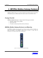
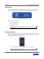
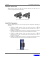
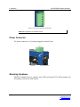
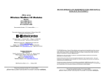
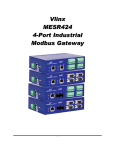
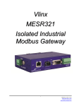
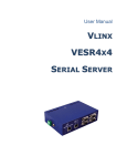
Vlinx
MESR9xx
Modbus Gateway
Manual Documentation Number MESR9xx-0109m
www.bb-elec.com
www.bb-europe.com
Vlinx MESR9xx
Documentation Number: MESR9xx-0109m
This product was designed and manufactured in Ottawa, Illinois USA
Using domestic and imported parts by
International Headquarters
B&B Electronics Mfg. Co. Inc.
707 Dayton Road
Ottawa, IL 61350 USA
Phone (815) 433-5100 -- General Fax (815) 433-5105
Website: www.bb-elec.com
European Headquarters
B&B Electronics Ltd.
Westlink Commercial Park
Oranmore, Co. Galway, Ireland
Phone +353 91-792444 -- Fax +353 91-792445
Website: www.bb-europe.com
Revision – One – January 2009
©2009 B&B Electronics Mfg. Co. Inc. No part of this publication may be reproduced or transmitted in any
form or by any means, electronic or mechanical, including photography, recording, or any information
storage and retrieval system without written consent. Information in this manual is subject to change
without notice, and does not represent a commitment on the part of B&B Electronics Mfg. Co. Inc.
B&B Electronics Mfg. Co. Inc. shall not be liable for incidental or consequential damages resulting from
the furnishing, performance, or use of this manual.
All brand names used in this manual are the registered trademarks of their respective owners. The use of trademarks or other designations in this
publication is for reference purposes only and does not constitute an endorsement by the trademark holder.
Manual Documentation Number MESR9xx-0109m
www.bb-elec.com
www.bb-europe.com
Table of Contents
Table of Contents
1. Introduction ....................................................................................................................................................... 1 About MESR9xx Modbus Gateways ..........................................................................................................................................1 MESR9xx Modbus Gateway Model Numbering .........................................................................................................................2 List of MESR9xx Modbus Gateway Models ...............................................................................................................................3 MESR9xx Modbus Gateway Features .......................................................................................................................................4 Vlinx Manager Configuration Software .......................................................................................................................................5 2. MESR9xx Modbus Gateway Hardware ............................................................................................................ 6 Package Checklist ......................................................................................................................................................................6 MESR9xx Modbus Gateway Enclosures and Mounting.............................................................................................................6 LED Indicators ............................................................................................................................................................................7 E1/E2 Ethernet Link LED .............................................................................................................................................. 7 Ready LED ..................................................................................................................................................................... 7 Serial Port LEDs ............................................................................................................................................................ 7 Mode Switch ...............................................................................................................................................................................8 Ethernet Connector ....................................................................................................................................................................8 Fiberoptic Connectors ................................................................................................................................................................9 Serial Port Connectors ...............................................................................................................................................................9 Power Connector .....................................................................................................................................................................10 Mounting Hardware ..................................................................................................................................................................10 3. Modbus Gateway Setup and Connections ................................................................................................... 12 Connecting the Power Supply ..................................................................................................................................................12 Connecting MESR9xx Modbus Gateways to Modbus networks ..............................................................................................12 Connecting the MESR9x1-x ......................................................................................................................................... 13 Connecting the MESR9x2T-x ....................................................................................................................................... 14 Connecting the MESR9x2D-x....................................................................................................................................... 14 Connecting MESR9xx Modbus Gateways to a Network ..........................................................................................................15 Network Connection (10BaseT/100BaseTX) ................................................................................................................ 15 Fiberoptic Connection ................................................................................................................................................. 15 MESR9xx Modbus Gateway Configuration Connections .........................................................................................................15 Configuring the MESR9xx Modbus Gateway via the Network Connection .................................................................. 16 Configuring the MESR9xx Modbus Gateway on Networks without a DHCP Server ................................................... 17 Configuring the MESR9xx Modbus Gateway via the Serial Port (Console Mode) ...................................................... 20 MESR9xx Modbus Gateway Operational Connections............................................................................................................21 Using MESR9xx Modbus Gateways in Direct IP Mode ............................................................................................... 21 Initiating a Hardware Reset on the Modbus Gateway ..............................................................................................................22 Reloading Factory Defaults ......................................................................................................................................................22 4. Description, Modbus Gateway Properties .................................................................................................... 23 Attached ...................................................................................................................................................................................23 Baud Rate ................................................................................................................................................................................23 Character Timeout ...................................................................................................................................................................23 Configuration Files ...................................................................................................................................................................23 Data/Parity/Stop .......................................................................................................................................................................24 Default Gateway .......................................................................................................................................................................24 DHCP .......................................................................................................................................................................................24 Firmware Version .....................................................................................................................................................................25 Hardware Version ....................................................................................................................................................................25 ID Routing ................................................................................................................................................................................25 IP Address ................................................................................................................................................................................25 Link Status ...............................................................................................................................................................................26 MAC Address ...........................................................................................................................................................................26 Modbus Priority ........................................................................................................................................................................26 Modbus Serial Retries ..............................................................................................................................................................26 Modbus ASCII ..........................................................................................................................................................................26 Page i
Manual Documentation Number MESR9xx-0109m
www.bb-elec.com/
www.bb-europe.com/
Table of Contents
Modbus Message Buffering .....................................................................................................................................................27 Modbus Message Timeout .......................................................................................................................................................27 Modbus RTU Message ............................................................................................................................................................27 Modbus Serial Control ..............................................................................................................................................................27 Modbus TCP Message .............................................................................................................................................................28 Model .......................................................................................................................................................................................28 Network Mode ..........................................................................................................................................................................28 Network Protocols ....................................................................................................................................................................28 Password .................................................................................................................................................................................28 Port# ID Remap .......................................................................................................................................................................29 Serial Interface Modes .............................................................................................................................................................29 Modbus Gateway Name ...........................................................................................................................................................30 Gateway Serial Port Number ...................................................................................................................................................30 Subnet Mask ............................................................................................................................................................................30 TCP (Transmission Control Protocol) ......................................................................................................................................31 5. Upgrading the Modbus Gateway Firmware .................................................................................................. 32 Downloading Firmware Files ....................................................................................................................................................33 Uploading the Firmware to the Modbus Gateway ....................................................................................................................33 6. Diagnostics ..................................................................................................................................................... 35 Testing a Modbus Gateway Connection ..................................................................................................................................35 7. Application Examples..................................................................................................................................... 37 From Serial Master to Modbus Gateway, Slave IDs Configurable ...........................................................................................37 From Serial Masters To Ethernet Master, Slave IDs Fixed ......................................................................................................38 Keep Serial Master, Add Ethernet Master(s) ...........................................................................................................................38 Modbus RTU, ASCII, and TCP Integration ..............................................................................................................................39 8. Modbus Help ................................................................................................................................................... 40 Modbus ASCII/RTU Basics ......................................................................................................................................................40 Hints and Tips ..........................................................................................................................................................................41 9. Appendices ..................................................................................................................................................... 42 Appendix A: Default Gateway Settings ....................................................................................................................................43 Appendix B: Product Specifications .........................................................................................................................................44 General Specifications ................................................................................................................................................. 45 Controls, Indicators and Connector Specifications...................................................................................................... 46 Serial Interface Specifications ..................................................................................................................................... 47 Network Specifications ................................................................................................................................................. 48 Appendix C: Dimensional Diagrams ........................................................................................................................................49 Appendix D: Connector Pinouts ...............................................................................................................................................53 MESR901-x Serial Port Pinouts ................................................................................................................................... 53 MESR902D-x Serial Port Pinouts ................................................................................................................................ 55 MESR902T-x Serial Port Pinouts................................................................................................................................. 56 Standard Ethernet Cable RJ-45 Pin-out....................................................................................................................... 57 10. Page ii
Glossary .......................................................................................................................................................... 58 Manual Documentation Number MESR9xx-0109m
www.bb-elec.com/
www.bb-europe.com/
1. Introduction
Vlinx MESR9xx Modbus Gateway
1. Introduction
Thank you for purchasing a MESR9xx Modbus Gateway product! This product has been
manufactured to the highest standards of quality and performance to ensure your
complete satisfaction.
Figure 1. An MESR921 Modbus Gateway
About MESR9xx Modbus Gateways
MESR9xx Modbus Gateways connect Modbus networks (RS-232, RS-422 or RS-485)
to Ethernet networks, allowing the Modbus network to become a node on the network.
The serial ports can be accessed over a LAN/WAN using Direct IP Mode connections.
MESR9xx Modbus Gateways feature 10BaseT or 100BaseTX copper network media and
fiber optic media options, depending on the model. MESR9xx Modbus Gateways are
built for use in industrial environments, featuring an IP30 approved slim line DIN rail
mountable case. They operate from a range of DC power supply voltages and feature
pluggable terminal block power connectors. An external power supply, sold separately, is
required. The photograph above is an MESR921 gateway. The MESR92x units have an
additional Ethernet port which functions much like an Ethernet Switch. MESR90x units
have one Ethernet port.
Page 1
Manual Documentation Number MESR9xx-0109m
www.bb-elec.com/
www.bb-europe.com/
1. Introduction
Vlinx MESR9xx Modbus Gateway
MESR9xx Modbus Gateway Model Numbering
MESR9xx Modbus Gateways are a growing family of products. Models are available
with one or two serial connections. Network connection options include
10BaseT/100BaseTX copper or several different fiber optic options. The following
diagram shows the model numbering scheme:
Page 2
Manual Documentation Number MESR9xx-0109m
www.bb-elec.com/
www.bb-europe.com/
1. Introduction
Vlinx MESR9xx Modbus Gateway
List of MESR9xx Modbus Gateway Models
The following table lists the various MESR9xx Modbus Gateway models available.
Model Number
MESR922T
2 RJ45 Copper, 2 port MEI with TB
MESR922T-MT
1 Multi-mode ST, 1 RJ45 Copper, 2 port MEI with TB
MESR922T-MC
1 Multi-mode SC, 1 RJ45 Copper, 2 port MEI with TB
MESR922T-ST
1 Single-mode ST, 1 RJ45 Copper, 2 port MEI with TB
MESR922T-SC
1 Single-mode SC, 1 RJ45 Copper, 2 port MEI with TB
MESR922T-ST40
1 Single-mode 40 Km ST, 1 RJ45 Copper, 2 port MEI with TB
MESR922T-SC40
1 Single-mode 40 Km SC, 1 RJ45 Copper, 2 port MEI with TB
MESR922T-ST80
1 Single-mode 80 Km ST, 1 RJ45 Copper, 2 port MEI with TB
MESR922T-SC80
1 Single-mode 80 Km SC, 1 RJ45 Copper, 2 port MEI with TB
MESR921
2 RJ45 Copper, 1 port MEI with TB/DB9 Male
MESR921-MT
1 Multi-mode ST, 1 RJ45 Copper, 1 port MEI with TB/DB9 Male
MESR921-MC
1 Multi-mode SC, 1 RJ45 Copper, 1 port MEI with TB/DB9 Male
MESR921-ST
1 Single-mode ST, 1 RJ45 Copper, 1 port MEI with TB/DB9 Male
MESR921-SC
1 Single-mode SC, 1 RJ45 Copper, 1 port MEI with TB/DB9 Male
MESR921-ST40
1 Single-mode 40 Km ST, 1 RJ45 Copper, 1 port MEI with TB/DB9 Male
MESR921-SC40
1 Single-mode 40 Km SC, 1 RJ45 Copper, 2 port MEI with DB9 Male
MESR921-ST80
1 Single-mode 80 Km ST, 1 RJ45 Copper, 1 port MEI with TB/DB9 Male
MESR921-SC80
1 Single-mode 80 Km SC, 1 RJ45 Copper, 1 port MEI with TB/DB9 Male
MESR902T
1 RJ45 Copper, 2 port MEI with TB
MESR902T-MT
1 Multi-mode ST, 2 port MEI with TB
MESR902T-MC
1 Multi-mode SC, 2 port MEI with TB
MESR902T-ST
1 Single-mode ST, 2 port MEI with TB
MESR902T-SC
1 Single-mode SC, 2 port MEI with TB
MESR902T-ST40
Page 3
Features
1 Single-mode 40 Km ST, 2 port MEI with TB
Manual Documentation Number MESR9xx-0109m
www.bb-elec.com/
www.bb-europe.com/
1. Introduction
Vlinx MESR9xx Modbus Gateway
Model Number
Features
MESR902T-SC40
1 Single-mode 40 Km SC, 2 port MEI with TB
MESR902T-ST80
1 Single-mode 80 Km ST, 2 port MEI with TB
MESR902T-SC80
1 Single-mode 80 Km SC, 2 port MEI with TB
MESR901
1 RJ45 Copper, 1 port MEI with TB/DB9 Male
MESR901-MT
1 Multi-mode ST, 1 port MEI with TB/DB9 Male
MESR901-MC
1 Multi-mode SC, 1 port MEI with TB/DB9 Male
MESR901-ST
1 Single-mode ST, 1 port MEI with TB/DB9 Male
MESR901-SC
1 Single-mode SC, 1 port MEI with TB/DB9 Male
MESR901-ST40
1 Single-mode 40 Km ST, 1 port MEI with TB/DB9 Male
MESR901-SC40
1 Single-mode 40 Km SC, 2 port MEI with DB9 Male
MESR901-ST80
1 Single-mode 80 Km ST, 1 port MEI with TB/DB9 Male
MESR901-SC80
1 Single-mode 80 Km SC, 1 port MEI with TB/DB9 Male
MESR9xx Modbus Gateway Features
•
•
•
•
•
•
•
•
Page 4
Four series models
•
MESR901-x (single serial port, single Ethernet Port)
•
MESR902T-x (two serial ports with pluggable terminal blocks, single Ethernet
port)
•
MESR921-x (single serial port, two Ethernet Ports)
•
MESR922T-x (two serial ports with pluggable terminal blocks, two Ethernet
Ports)
•
On models with two Ethernet Ports, the second port is an Ethernet passthrough port. This port functions much like an unmanaged switch.
Fiber models available for each of the above series
Multi-interface serial ports
DB-9M and pluggable terminal block serial port connector options
All ports are software selectable as RS-232, RS-422 or RS-485 2- and 4-wire
Configuration can be done via network or direct serial connection
Slim line DIN rail mountable case
Accepts DC power over a wide voltage range
Manual Documentation Number MESR9xx-0109m
www.bb-elec.com/
www.bb-europe.com/
1. Introduction
•
•
•
•
•
•
Vlinx MESR9xx Modbus Gateway
10/100 Mbps Ethernet with Auto Selection, Auto MDI/MDIX
LAN and WAN Communications
TCP Client or Server operation - configurable
Firmware Upload for future revisions/upgrades
Software Support - Windows 2000/2003 Server/XP/Vista x32
Configuration of Ethernet and serial port settings using Vlinx Manager software
Vlinx Manager Configuration Software
Vlinx Manager configuration software enables you to find connected Modbus gateways,
configure them, upgrade Modbus gateway firmware, and save/load configuration files. It
features a graphical user interface (GUI) that is convenient and easy to use.
Page 5
Manual Documentation Number MESR9xx-0109m
www.bb-elec.com/
www.bb-europe.com/
2. Hardware
Vlinx MESR9xx Modbus Gateway
2. MESR9xx Modbus Gateway Hardware
MESR9xx Modbus Gateways are enclosed in DIN rail mountable enclosures and feature
LED indicators, power, Ethernet and serial connectors and a recessed Mode switch.
Package Checklist
MESR9xx Modbus Gateways are shipped with the following items included:
•
•
•
MESR9xx Modbus Gateway Module
Quick Start Guide
CD with User Manual, Quick Start Guide and firmware
MESR9xx Modbus Gateway Enclosures and Mounting
All MESR9xx Modbus Gateway models are built into similar enclosures. Modules are
DIN rail mountable. The MESR92x (shown below) enclosure is larger than the
MESR90x.See the specification table for dimensions.
Figure 2. Front View of an MESR921 Modbus Gateway
Page 6
Manual Documentation Number MESR9xx-0109m
www.bb-elec.com/
www.bb-europe.com/
2. Hardware
Vlinx MESR9xx Modbus Gateway
LED Indicators
MESR9xx Modbus Gateways have three types of LED indicators: Ethernet Link LEDs,
a Ready LED and Serial Port LEDs.
Figure 3. Ready Ethernet Port LEDs on 1 and 2 Ethernet Port Modbus Gateways
E1/E2 Ethernet Link LED
The Ethernet Link LED (E1 or E2) illuminates (green) if the Ethernet is connected.
When the LED is blinking it indicates that there is data traffic on the Ethernet link.
E1 is used for all models to connect to the network. E2 is used on MESR92X models, and
is a pass-through Ethernet connector.
Ready LED
The Ready LED (green) blinks if the system is operating correctly, once per second in
normal operating conditions, or three times per second in reset, configuration mode, or
when loading factory defaults. If the LED is off or steady, it indicates the system is not
operating correctly.
Serial Port LEDs
MESR901-x Modbus Gateways feature one serial port. MESR902D, and MESR902T-x
Modbus Gateways feature two serial ports. Each serial port has an associated LED. Serial
Port LEDs blink (green) when data is being transmitted or received on the serial port.
When the LED is On it indicates the serial port is open.
Figure 4. Serial Port LEDs on 1 and 2 Serial Port Modbus Gateways
Page 7
Manual Documentation Number MESR9xx-0109m
www.bb-elec.com/
www.bb-europe.com/
2. Hardware
Vlinx MESR9xx Modbus Gateway
Mode Switch
A recessed momentary reset switch is located on the top of the enclosure. To activate the
switch, insert a small plastic tool through the hole in the enclosure and press lightly.
Figure 5.
Mode Switch
The Mode switch can be used to:
•
•
•
Initiate a Hardware Reset
Enter Console Mode
Reload factory defaults
Note: Refer to Section 3. Modbus Gateway Setup and Connections for more information on using
the Mode switch.
Ethernet Connector
Modbus gateway models using 10BaseT/100BaseTX network connections use an RJ45
receptacle. The Modbus gateway is connected to a standard Ethernet network drop using
a straight-through RJ45 (male) Ethernet cable.
Figure 6.
Ethernet Connectors. E2 is pass-through connection on model shown
Note: Refer to Appendix D for connection pin-outs.
Page 8
Manual Documentation Number MESR9xx-0109m
www.bb-elec.com/
www.bb-europe.com/
2. Hardware
Vlinx MESR9xx Modbus Gateway
Fiberoptic Connectors
Modbus gateway models using fiber optic network connections use either SC or ST
connectors, depending on the specific model.
Figure 7. SC and ST Fiberoptic Cable Connectors
Serial Port Connectors
MESR9xx Modbus Gateways use four serial port connector configurations, depending on
the model:
•
•
•
•
MESR901-x Modbus Gateways feature one serial port and use a DB-9M
connector for RS-232 and a five-position removeable terminal block for RS-422
and RS-485 connections.
MESR902T-x Modbus Gateways feature two serial ports, both using five-position
removable terminal blocks for RS-232, RS-422 and RS-485 connections.
MESR921-x Modbus Gateways feature one serial port and use a DB-9M
connector for RS-232 and a five-position removeable terminal block for RS-422
and RS-485 connections.
MESR922T-x Modbus Gateways feature two serial ports, both using five-position
removable terminal blocks for RS-232, RS-422 and RS-485 connections.
Figure 8. DB-9 Female Serial Port Connector
Page 9
Manual Documentation Number MESR9xx-0109m
www.bb-elec.com/
www.bb-europe.com/
2. Hardware
Vlinx MESR9xx Modbus Gateway
Figure 9. Five-Position Pluggable Terminal Block
Note: Refer to Appendix D for connection pin-outs.
Power Connector
The power connector is a 2-position pluggable terminal block.
Figure 10.
Power Connection
Mounting Hardware
MESR9xx Modbus Gateway modules can be DIN rail mounted. The DIN mounting clip
and spring is included on each module.
Page 10
Manual Documentation Number MESR9xx-0109m
www.bb-elec.com/
www.bb-europe.com/
2. Hardware
Figure 11.
Page 11
Vlinx MESR9xx Modbus Gateway
DIN Clips on Modbus Gateway Modules. Large DIN clips are used on MESR92x, small DIN clips on MESR90x.
Manual Documentation Number MESR9xx-0109m
www.bb-elec.com/
www.bb-europe.com/
3. Setup and Connections
Vlinx MESR9xx Modbus Gateway
3. Modbus Gateway Setup and Connections
This section describes how to setup and connect MESR9xx Modbus Gateways.
Note: In this section devices to be connected to the Modbus gateway’s serial connection are simply
referred to as the “Modbus network”.
Connecting the Power Supply
Connect a DC power supply to the power terminals on the top of the Modbus gateway.
Polarity of the wires is indicated on the label on the side of the Modbus gateway.
Acceptable voltages are between 10 VDC and 48 VDC. The power supply must be
capable of supplying 4 Watts for MESR90x units or 6 Watts fro MESR92x units.
Figure 12.
MESR Power Connection
Connecting MESR9xx Modbus Gateways to Modbus networks
MESR9xx Modbus Gateways can be configured to connect to Modbus networks using
RS-232, RS-422, RS-485 2-wire and RS-485 4-wire.
Page 12
Manual Documentation Number MESR9xx-0109m
www.bb-elec.com/
www.bb-europe.com/
3. Setup and Connections
Vlinx MESR9xx Modbus Gateway
RS-232 connections support eight signal lines plus Signal Ground. Signals are single
ended and referenced to Ground. Default communications parameters are 9600, 8, N, 1
and no flow control implemented.
RS-422 connections support two signal pairs: RXA(-), RXB(+) and TXA(-), TXA(+),
plus GND. The data lines are differential pairs (A & B) in which the B line is positive
relative to the A line in the idle (mark) state. Ground provides a common mode reference.
RS-485 connections support 2-wire or 4-wire operation.
When configured for 4-wire operation the connection supports two signal pairs: RXA(-),
RXB(+) and TXA(-), TXA(+), plus GND. This makes full-duplex operation possible.
The data lines are differential pairs (A & B) in which the B line is positive relative to the
A line in the idle (mark) state. Ground provides a common mode reference.
When configured for 2-wire operation the connection supports one signal pair: DataB(+)
and DataA(-) signal channels using half-duplex operation. The data lines are differential
with the Data B line positive relative to Data A in the idle (mark) state. Ground provides
a common mode reference.
Connecting the MESR9x1-x
The MESR9x1-x has one serial connection that supports RS-232, RS-422 and RS-485
(2- and 4-wire). The unit has two connectors: a DB-9M connector and a 5-position
terminal block.
If you select RS-232 mode when you configure the Modbus gateway, you must connect
the Modbus network to the Modbus gateway via a serial cable. The MESR901 is a DTE.
If the Modbus network is a DTE, use a null modem (cross-over) cable. If the Modbus
network is a DCE, use a straight-through cable.
If you select RS-422 mode, RS-485 2-wire mode, or RS-485 4-wire mode when you
configure the Modbus gateway, you must connect the Modbus network appropriately, via
the 5-position terminal block.
Note: Refer to Appendix D for connector pinout information.
Page 13
Manual Documentation Number MESR9xx-0109m
www.bb-elec.com/
www.bb-europe.com/
3. Setup and Connections
Vlinx MESR9xx Modbus Gateway
Figure 13.
MESR901 Connections
Connecting the MESR9x2T-x
The MESR9x2T-x has two serial connections that support RS-232, RS-422 and RS-485
(2- and 4-wire). The unit has two connectors, both of which are 5-position terminal
blocks. Make the appropriate connections to the terminal blocks to match the serial
connection mode you select when configuring the Modbus gateway.
Note: Refer to Appendix D for connector pinout information.
Figure 14.
MESR902T-x Connections
Connecting the MESR9x2D-x
The MESR9x2D-x has two serial connections that support RS-232, RS-422 and RS-485
(2- and 4-wire). The unit has two connectors, both of which are DB-9M connectors. You
must connect the Modbus network to the Modbus gateway via a serial cable. The
MESR902D is a DTE. If the Modbus network is a DTE, use a null modem (cross-over)
cable. If the Modbus network is a DCE, use a straight-through cable.
Note: Refer to Appendix D for connector pin-out information.
Page 14
Manual Documentation Number MESR9xx-0109m
www.bb-elec.com/
www.bb-europe.com/
3. Setup and Connections
Vlinx MESR9xx Modbus Gateway
Figure 15.
MESR902D-x Connections
Connecting MESR9xx Modbus Gateways to a Network
Network Connection (10BaseT/100BaseTX)
When connecting a Modbus gateway equipped with a 10BaseT/100BaseTX network
connection (RJ45 connector) a standard network cable is connected from the Modbus
gateway to a network drop. PCs configuring and/or communicating with the Modbus
gateway are also connected to the network.
Fiberoptic Connection
When connecting a Modbus gateway equipped with a fiberoptic interface to a
fiberoptic link the appropriate fiberoptic cable must be connected between the Modbus
gateway and the network interface. Refer to Figure 2, “List of MESR9xx Modbus
Gateway Models” at the beginning of this manual for a list of supported fiber types,
distances and connectors.
MESR9xx Modbus Gateway Configuration Connections
MESR9xx Modbus Gateways can be configured over the network or via a serial port.
Page 15
Manual Documentation Number MESR9xx-0109m
www.bb-elec.com/
www.bb-europe.com/
3. Setup and Connections
Vlinx MESR9xx Modbus Gateway
Configuring the MESR9xx Modbus Gateway via the Network Connection
When configuring via the network, either Vlinx Manager software or the web interface
can be used.
Configuring with Vlinx Manager
MESR9xx Modbus Gateways can be configured over the network Vlinx Manager
software running on a PC.
To open Vlinx Manager:
1. From the Desktop, click Start Æ Programs Æ B&B Electronics Æ Vlinx Æ Modbus
Gateway Manager Æ Configuration Manager.
The Vlinx Manager Device Discovery window appears.
Figure 16.
Vlinx Manager Discovery Window
2. Configure your Modbus gateway as required.
Note: For more information on configuration options refer to Section 4: Description of Modbus
gateway Properties.
Configuring with the Web Interface
MESR9xx Modbus Gateways can be configured over the network using a standard
internet browser such as Internet Explorer or Firefox.
To open the web configuration interface:
1. On a PC connected to the network, open a browser.
Page 16
Manual Documentation Number MESR9xx-0109m
www.bb-elec.com/
www.bb-europe.com/
3. Setup and Connections
Vlinx MESR9xx Modbus Gateway
2. In the browser’s address bar, type the IP address of the Modbus gateway.
Note: Your Modbus gateway comes from the factory pre-configured to receive an IP address
assignment from a DHCP server. If a DHCP Server is not available on your network, it will default
to 169.254.102.39.
The web interface Login page appears.
Figure 17.
Vlinx Manager Login Screen
3. Configure your Modbus gateway as required.
Note: For more information on configuration options refer to Section 4: Description of Modbus
Gateway Properties.
Configuring the MESR9xx Modbus Gateway on Networks without a DHCP
Server
Your Modbus Gateway comes from the factory set up to receive an IP assignment from a
DHCP Server. If there is not a DHCP server on your network, the Modbus Gateway will
default to IP address 169.254.102.39. If this address does not work with your PC, there
are two methods to manually configure the network information.
1. Method 1: Change your PC Network to Match the Modbus Gateway
a. Open your network connection
Page 17
Manual Documentation Number MESR9xx-0109m
www.bb-elec.com/
www.bb-europe.com/
3. Setup and Connections
Vlinx MESR9xx Modbus Gateway
b. Click on Internet Protocol (TCP/IP) and click <properties>. Change the
parameters to the following:
IP Address = 169.254.102.1
Subnet Mask = 255.255.0.0
Default Gateway = 169.254.102.100
c. Use the Vlinx™ Manager Software to search for, discover, and configure the
Modbus Gateway.
Page 18
Manual Documentation Number MESR9xx-0109m
www.bb-elec.com/
www.bb-europe.com/
3. Setup and Connections
Vlinx MESR9xx Modbus Gateway
2. Method 2: Change the Modbus Gateway’s network settings to match your PC using
Console Mode
a. Connect a null modem serial cable (crossover cable) from port 1 on the
Modbus Gateway to an available COM port on your PC.
b. Open Hyper Terminal or similar serial emulation software and connect to the
COM port used in step one. Ensure the port is configured to 115,200 baud, 8
data bits, no parity, and 1 stop bit.
c. Enter Console Mode. Press and hold the Modbus Gateway’s for 2 to 10
seconds. The LED indicators will respond as follows:
Model
Port 1 LED
Port 2 LED Ready LED
MESR9x1
OFF
XXXXXXX
ON
MESR9x2
OFF
ON
OFF
d. Release the reset button. The READY LED will blink once per second for five
seconds. This indicates that the Modbus Gateway is re-booting in Console
Mode.
e. When the Modbus Gateway has successfully restarted in Console Mode, the
READY LED will be OFF and the PORT 1 LED will be ON.
f. Open the Vlinx™ Manager Software and select “Serial Port” as the method to
connect to the Modbus Gateway.
g. After logging in, click on <Network>.
h. Un-check the box next to “I Want DHCP to setup the Network.”
i. Re-configure the Modbus Gateway’s network settings to something within the
range of your PC’s network settings. For example:
PC Network Settings
IP Address = 192.168.0.1
Subnet Mask = 255.255.0.0
Default Gateway = 192.168.0.100
Change the Modbus Gateway’s network settings to:
IP Address = 192.168.0.50
Subnet Mask = 255.255.0.0
Default Gateway = 192.168.0.100
Page 19
Manual Documentation Number MESR9xx-0109m
www.bb-elec.com/
www.bb-europe.com/
3. Setup and Connections
Vlinx MESR9xx Modbus Gateway
j. Save the settings and remove power from the Modbus Gateway.
k. Re-apply power. Open the Vlinx™ Manager Software and select “Network”
as the method to connect to the device.
Configuring the MESR9xx Modbus Gateway via the Serial Port (Console
Mode)
Your Modbus gateway can be configured via a serial port using Vlinx Manager. To use
this feature the Modbus gateway's serial port must be connected to the serial port of a PC
(using a null modem cable).
Figure 18.
Console Mode Setup
To configure the Modbus gateway it must be put into Console Mode, using the Mode
switch.
To enter Console Mode, press and hold the Mode switch for between two and ten
seconds. The LED indicators respond as follows:
1. The Ready LED blinks three times per second while the button is being pressed.
2. The Modbus gateway is in Console Mode when:
• On the MESR901: Port 1 LED is On and the Ready LED is Off.
• On MESR902x models: Port 1 LED is On and the Port 2 LED is Off.
To configure the Modbus gateway, open the Vlinx Manager software and set up the
Modbus gateway's parameters as required.
Note: For more information on configuration options refer to Section 4: Description of Modbus
Gateway Properties.
To exit Console Mode, press and hold the Reset switch for two seconds, or turn off the
power from the MESR9xx, wait a few seconds, and turn the power on again.
Page 20
Manual Documentation Number MESR9xx-0109m
www.bb-elec.com/
www.bb-europe.com/
3. Setup and Connections
Vlinx MESR9xx Modbus Gateway
The LEDs go back to their normal states when the device resumes normal operation.
MESR9xx Modbus Gateway Operational Connections
MESR9xx Modbus Gateways can operate in Direct IP Mode.
Using MESR9xx Modbus Gateways in Direct IP Mode
A Direct IP connection allows applications using TCP/IP socket programs to
communicate with the COM ports on the Modbus gateway. In this type of application the
Modbus gateway is configured as a TCP server. The socket program running on the PC
establishes a communication connection with the Modbus gateway. The data is sent
directly to and from the serial port on the server.
To set up a Direct IP Mode connection:
1. Connect the Modbus gateway to the network and a Modbus network as described in
previous sections.
2. Configure the Modbus gateway with the appropriate network settings (using Vlinx
Manager or the web interface).
3. Configure your software application with the appropriate IP address and port number
to communicate with the Modbus network(s).
Figure 19.
Page 21
Direct IP Connection
Manual Documentation Number MESR9xx-0109m
www.bb-elec.com/
www.bb-europe.com/
3. Setup and Connections
Vlinx MESR9xx Modbus Gateway
Initiating a Hardware Reset on the Modbus Gateway
To initiate a Hardware Reset on the Modbus gateway, press and hold the Mode switch
for 0 to 2 seconds, and then release it. The LED indicators respond as follows:
1. The Ready LED blinks three times per second while the button is being pressed.
2. The Modbus gateway is in Reset Mode when:
• On the MESR901: Port 1 LED is On and the Ready LED is Off.
• On MESR902x models: Port 1 LED is On and the Port 2 LED is Off.
3. The LEDs go back to their normal states when the device resumes normal operation.
Reloading Factory Defaults
To reload Factory Defaults, press and hold the Mode switch for more than 10 seconds.
The LED indicators respond as follows:
1. The Ready LED blinks three times per second while the button is being pressed.
2. The Modbus gateway is in Factory Default Mode when:
• On the MESR901: Port 1 LED and the Ready LED are both On.
• On MESR902x models: Port 1 LED and the Port 2 LED are both On.
The Modbus gateway reloads all factory default configuration parameters.
3. The LEDs go back to their normal states when the device resumes normal operation.
Note: Factor default parameters are listed in Appendix A
Page 22
Manual Documentation Number MESR9xx-0109m
www.bb-elec.com/
www.bb-europe.com/
4. Properties
Vlinx MESR9xx Modbus Gateway
4. Description, Modbus Gateway Properties
The following MESR9xx Modbus Gateway properties are ordered alphabetically to assist
you in finding the information you need.
Attached
The Attached is selectable between Master and Slaves. If Master is selected, it will run in
TCP server mode, if Slaves is selected, it will run in TCP client mode.
Baud Rate
Baud Rate is the communication speed of the link between the Modbus gateway and the
device attached to its serial port. Both these devices must be configured to operate at the
same baud rate. Baud rate values range from 75 to 230,400 Baud. (Refer to Appendix B
for specific baud rates that are supported.)
Character Timeout
Character Timeout controls the maximum duration between received characters before
sending the characters to the network. Larger values may decrease the number of network
packets, but increase the amount of time to receive characters. Smaller values may
increase the number of network packets, but decrease the amount of time to receive
characters. The range is 1 through 65535.
Configuration Files
Configuration files contain all configuration settings for the Modbus gateway. When the
Modbus gateway settings have been configured you can save the settings using Vlinx
Manager. Existing configuration files can be Opened (from Vlinx Manager), which loads
them into the Modbus gateway. This allows the same configuration to be applied to
multiple Modbus gateways, or to reload a previously used configuration.
Page 23
Manual Documentation Number MESR9xx-0109m
www.bb-elec.com/
www.bb-europe.com/
4. Properties
Vlinx MESR9xx Modbus Gateway
Data/Parity/Stop
The number of Data bits, type of Parity and number of Stop bits selected define the
serial port parameters at which the Modbus gateway will operate. These parameters must
be configured to match the parameters set on the Modbus network connected to the
Modbus gateway's serial port.
Data Bits controls the number of bits of data in each character. Options include 5, 6, 7 or
8 data bits.
Parity controls the error checking mode. Options are No Parity, Odd, Even, Mark or
Space.
Stop Bits controls the number of bits to indicate the end of a character. Options include
1, 1.5 and 2. (1.5 bits is only valid when 5 data bits is selected, which is rare. The 2 stop
bits setting is only valid when 6, 7 or 8 data bits is selected.)
Default Gateway
The Default Gateway address sets the default route to remote networks, enabling users
to access the Modbus gateway from outside the local network.
DHCP
DHCP (Dynamic Host Configuration Protocol) is a protocol used on special servers
that supply IP addresses to network nodes on request.
When DHCP is enabled on the Modbus gateway (factory default), on power up it sends a
DHCP request to the DHCP server, which assigns a dynamic IP address, subnet mask,
and default server to the Modbus gateway.
When DHCP is disabled (static IP addressing), the IP Address, Subnet and Default
Gateway fields must be set manually by entering the appropriate addresses in these fields.
If you do not know what addresses to use in these fields, ask your network administrator.
Notes:
A dynamic address assigned by the DHCP server may change if the server loses the Ethernet
connection or power is removed. If a device on the network that normally communicates with the
Modbus gateway is configured to communicate with a specific IP address of the Modbus gateway,
and the IP address has been changed, the device will not be able to communicate with the Modbus
gateway. Therefore, disabling DHCP and using a static IP address is recommended. If a DHCP
server is not found on the network, the Modbus gateway automatically configures to IP address
169.254.102.39
Page 24
Manual Documentation Number MESR9xx-0109m
www.bb-elec.com/
www.bb-europe.com/
4. Properties
Vlinx MESR9xx Modbus Gateway
Firmware Version
The Firmware Version number (Vx.x.x) indicates the Modbus gateway's currently
loaded firmware release. From time to time new firmware is made available and can be
uploaded into the Modbus gateway using Vlinx Manager.
Hardware Version
The Hardware Version number of the Modbus gateway hardware is displayed on the
Login page of Vlinx Manager.
ID Routing
ID routing allows the gateway to manage slave device IDs between various Modbus
interfaces. By filling in the user defined slave ID table, a Modbus Gateway routes
requests to the correct serial port. One connection can command serial slaves on multiple
serial ports.
By filling in the drop down menu of ports with slave devices attached, adding IP
addresses of slaves, up to 10 address ranges can be routed.
By default all boxes are unchecked, the drop down menu is set to serial port one, and all
fill in boxes are blank.
IP Address
Software or hardware attempting to access the Modbus gateway via the network must
know the IP Address of the server. If DHCP is selected, the Modbus gateway requests
and receives a dynamic IP address from a DHCP server when it first connects to the
network. If DHCP is not selected you must type in a static IP address when configuring
Network settings (on the Vlinx Manager Network page). The static IP address remains
the same each time the server is powered up or starts/restarts.
MESR9xx Modbus gateways come from the factory preset to receive an IP assignment
from a DHCP Server. If a DHCP Server is not available on your network, it will default
to 169.254.102.39. If you need to change the static IP address and do not know what
address to use, consult your network administrator.
Page 25
Manual Documentation Number MESR9xx-0109m
www.bb-elec.com/
www.bb-europe.com/
4. Properties
Vlinx MESR9xx Modbus Gateway
Link Status
Link Status of the currently selected Modbus gateway is shown on the Login page of
Vlinx Manager. Link status indicates the type of Ethernet connection between the
computer and Modbus gateway. It will either display 10BaseT or 100BaseTX in full
duplex or half duplex. Link status is dependant on the LAN, switches, hubs used in the
LAN topology.
MAC Address
The MAC Address is a hardware level address of the Modbus gateway that cannot be
changed. It is assigned in the factory. Every Ethernet device manufactured has it own
unique MAC address. The MAC address of each Modbus gateway is printed on the
device's label. The MAC address of the currently selected Modbus gateway is also
displayed on the Login page of Vlinx Manager.
Modbus Priority
This allows the gateway to move high priority messages to the front of the serial message
buffer. The priority can be based on the originating IP address, the Modbus ID, the
Modbus function code, or any combination of the three. Up to five different priorities
can be set.
The default will have all the check boxes unchecked and all the fill in boxes blank.
Modbus Serial Retries
This is the maximum number of times that the Modbus gateway will retry to send a
Modbus message to a Modbus client, before reporting a 0Bh exception if it is selected.
This should be limited to between 0 and 5.
Modbus ASCII
The Modbus ASCII message protocol is a human readable version of the Modbus
message, and is one of the three Modbus formats supported by the MESR9xx Modbus
Gateway.
A major advantage of Modbus ASCII is it allows up to a 1 second gap between bytes. It
uses a Longitudinal Redundancy Check (LRC) checksum to verify message accuracy.
Page 26
Manual Documentation Number MESR9xx-0109m
www.bb-elec.com/
www.bb-europe.com/
4. Properties
Vlinx MESR9xx Modbus Gateway
Modbus Message Buffering
The MESR9xx has two Modbus serial buffers, one for each serial port. Each will buffer
up to 32 Modbus messages. These buffers help ensure messages don’t get lost in a data
traffic jam, and are part of what makes Modbus such an outstandingly reliable serial
protocol.
Modbus Message Timeout
Message timeout is supported by the MESR9xx. This is the maximum amount of time
before a response to a message is expected.
Modbus RTU Message
The Modbus RTU message is broken into 4 different parts. The address field, the
function code, this is copied directly over from the Modbus TCP message, the data and
the error check, a 16 bit cyclic redundancy check or CRC.
Modbus Serial Control
Message Timeout
The message timeout is the maximum time the gateway allows for a response from the
slave device. The default is 1000ms.
Character Timeout
The character timeout is the maximum time the gateway allows between characters from
the slave device, used only in RTU mode. The default is 10ms.
CRC/LRC Error Check
The CRC/LRC check calculates the CRC/LRC for the message received, and compares
this to the CRC/LRC with the message. If not the same the message is rejected.
Page 27
Manual Documentation Number MESR9xx-0109m
www.bb-elec.com/
www.bb-europe.com/
4. Properties
Vlinx MESR9xx Modbus Gateway
Message Retries
Message retries is the number of times the gateway resends the message if it gets a
character timeout or CRC/LRC error. The default is two.
Modbus TCP Message
The Modbus TCP message may be broken up into multiple different TCP frames. The
Modbus TCP message contains three main blocks to the Modbus TCP message. The first
is the MBAP header. It describes the Modbus message, including the Transaction
Identifier, Protocol Identifier, Length and Unit ID. The second part is the Function Code.
The third is the Data. The Function Code and Data are the standard Modbus PDU.
Model
The Model number of the currently selected Modbus gateway is displayed on the Login
page of Vlinx Manager.
Network Mode
The network mode is the method used to configure the network parameters. It is either
“DHCP” or “Static IP”.
Network Protocols
Network Protocols available for use on MESR9xx Modbus gateways include TCP.
Password
When you first receive the MESR9xx Modbus gateway from the factory the Password is
blank so that you can initially access the Modbus gateway without entering a value into
this field. To ensure security you should create and save a password the first time you
configure the Modbus gateway. After a password has been set up it must be entered each
Page 28
Manual Documentation Number MESR9xx-0109m
www.bb-elec.com/
www.bb-europe.com/
4. Properties
Vlinx MESR9xx Modbus Gateway
time you login to Vlinx Manager. The password is used to access the configuration pages
from the Vlinx Manager Login page and can be changed from the General page.
Port# ID Remap
This allows the gateway to remap the Modbus ID to another ID on the serial port. This
would be used when there are two identical Modbus serial networks talking to Modbus
TCP controllers.
The first box is the staring ID of a range you want to remap; the second box is the last ID
of that range. If you are just remapping one ID the second box is not filled in. The third
box is the start of the remap range on the serial port. The fourth box will auto fill in
based on the range filled in the first 2 boxes. The range must check to make sure it is a
valid range, and does not overlap with any of the other ranges set. Up to 5 address ranges
can be remapped per port.
The default will have all the check boxes unchecked, and all fill in boxes blank.
Serial Interface Modes
Four serial interface modes of operation are:
•
•
•
•
RS-232 - Point-to-point serial communications connection used by PC COM ports
and many other systems. Capable of baud rates up to 115.2 kbaud over short
distances (typically 50 feet). Typically uses DB-9 connectors but terminals are
also used on MESR9xx Modbus gateways.
RS-422 - Point-to-point communications using a transmit pair and a receive pair.
RS-422 can operate at higher speeds and longer distances than RS-232. Typically
uses two shielded twisted pairs and screw terminals but DB-9 connectors are also
used on MESR9xx Modbus gateways.
RS-485 2-wire - Similar speed and distance specifications as RS-422 but allows
multidrop connections. Typically uses one shielded twisted pair and screw
terminals but DB-9 connectors are also used on MESR9xx Modbus gateways.
RS-485 4-wire - Similar speed and distance specifications as RS-422 but allows
multi-drop and full duplex connections. Typically uses two shielded twisted pairs
and screw terminals but DB-9 connectors are also used on MESR9xx Modbus
gateways..
Select the appropriate serial interface mode for the type of connection between the
Modbus gateway's serial port and the device connected to it.
Note: Refer to the Appendix D for connector and pin-out details.
Page 29
Manual Documentation Number MESR9xx-0109m
www.bb-elec.com/
www.bb-europe.com/
4. Properties
Vlinx MESR9xx Modbus Gateway
Modbus Gateway Name
Modbus Gateway Name is a unique name assigned to the Modbus gateway. It must be a
valid hostname as defined by RFC-952 and RFC-1123. The rules are:
•
•
•
It must consist only of the characters "A" to "Z", "a" to "z", "0" to "9" or "-"
It can start or end with a letter or a number, but it must not start or end with a "-".
It must not consist of all numeric values.
Gateway Serial Port Number
The Gateway Serial Port Number of the currently selected port is shown in this field.
•
•
MESR901-x Modbus Gateways feature one serial port.
MESR902D-x and MESR902T-x Modbus Gateways feature two serial ports.
Subnet Mask
The Subnet Mask specifies the network mask the Modbus gateway uses when on a
subnetted network.
•
•
•
•
•
Page 30
For a Class A network (IP addresses 0.0.0.0 through 127.255.255.255) the default
subnet mask is 255.0.0.0.
For a Class B network (IP addresses 128.0.0.0 through 191.255.255.255) the
default subnet mask is 255.255.0.0
For a Class C network (IP addresses 192.0.0.0 through 233.255.255.255) the
default subnet mask is 255.255.255.0
For a Class D network (IP addresses 224.0.0.0 through 239.255.255.255) and
Class E Networks (IP addresses 240.0.0.0 through 255.255.255.255) the subnet
mask is ignored.
MESR9xxModbus Gateways come from the factory with a default subnet mask
value of: 255.255.255.0
Manual Documentation Number MESR9xx-0109m
www.bb-elec.com/
www.bb-europe.com/
4. Properties
Vlinx MESR9xx Modbus Gateway
TCP (Transmission Control Protocol)
TCP (Transmission Control Protocol) provides reliable connection-oriented network
communication with error checking. In TCP mode the Modbus gateway can be
configured as a client or a server.
When the Modbus gateway is configured as a TCP client it initiates connections with a
server on the network. You must set up the IP address and port number of the server that
you want the client (Modbus gateway) to communicate with. You also select whether the
Modbus gateway is to connect at power up or only when it receives data from the device
connected to its serial port.
When the Modbus gateway is configured as a TCP server it waits for connections to be
initiated by another network device. You must set up the TCP port number that it will
listen to for connections and set the maximum (up to eight) number of simultaneous
connections it will accept. You can filter the connections it will accept based on specific
IP addresses or ranges of IP addresses that you specify.
Page 31
Manual Documentation Number MESR9xx-0109m
www.bb-elec.com/
www.bb-europe.com/
5. Upgrading Firmware
Vlinx MESR9xx Modbus Gateway
5. Upgrading the Modbus Gateway
Firmware
Occasionally, updated firmware may become available for your Modbus gateway. The
firmware can be upgraded using the Zlinx Manager software. The following procedure
describes the firmware updating process:
1. Click the Upgrade button to open the Firmware Upgrade dialog box.
Figure 20.
Firmware Upgrade Dialog Box
The name of the currently selected Modbus gateway appears in the top drop down
list. Other Modbus gateways (that have already been discovered) can be selected from
the drop down list, if desired.
Page 32
Manual Documentation Number MESR9xx-0109m
www.bb-elec.com/
www.bb-europe.com/
5. Upgrading Firmware
Vlinx MESR9xx Modbus Gateway
The current firmware version of the selected Modbus gateway is shown in the text
below the Modbus gateway name.
Information about the selected firmware file is shown in the third text box.
Downloading Firmware Files
The Firmware File list (second box) displays all firmware files in the firmware
installation folder. Only firmware that is compatible with the selected Modbus gateway is
available in this list.
To download the latest firmware files from an FTP site on the Internet:
1. Click the Internet button at the bottom of the window.
The Vlinx Manager connects to an FTP server on the Internet.
2. Click the Check for Updates button.
Progress Bar and Progress Box display information about and progress of the
download.
To download the latest firmware files from a file:
1. Click the Browse button to open an Open File dialog box.
2. Browse to the drive and folder containing the firmware file.
3. Select and download the file to the local firmware folder.
Uploading the Firmware to the Modbus Gateway
To upgrade the firmware:
1. In the Modbus Gateway Selection drop down list, select the Modbus gateway to be
upgraded.
2. In the Firmware Description drop down list, select the firmware to upload to the
Modbus gateway.
3. Click the Upgrade button.
Progress Bar and Progress Box provides information on the progress of the transfer.
4. In the Firmware File drop down list, select the firmware file to upload to the Modbus
gateway.
5. Click Upgrade.
The Progress box and Progress bar display information on the upgrading process.
Page 33
Manual Documentation Number MESR9xx-0109m
www.bb-elec.com/
www.bb-europe.com/
5. Upgrading Firmware
Vlinx MESR9xx Modbus Gateway
6. When the upgrade process is complete, click Close.
Page 34
Manual Documentation Number MESR9xx-0109m
www.bb-elec.com/
www.bb-europe.com/
6. Diagnostics
Vlinx MESR9xx Modbus Gateway
6. Diagnostics
Clicking the Diagnostics icon opens the Diagnostics dialog box and enables you to
check the operation of connected Modbus gateways on the local computer.
The Computer Information box displays information about the type of network
connections, the IP addresses, Subnet Masks and Default Gateways in use.
Figure 21.
Diagnostics Dialog Box
Testing a Modbus Gateway Connection
To run diagnostics on a Modbus gateway:
1. Click the Diagnostics icon.
The Diagnostics dialog box appears.
Page 35
Manual Documentation Number MESR9xx-0109m
www.bb-elec.com/
www.bb-europe.com/
6. Diagnostics
Vlinx MESR9xx Modbus Gateway
2. In the drop down box select the specific Modbus gateway you want to check.
3. Click the Start button
Information about the progress of the pinging process is displayed in the Test
Progress box.
Figure 22.
Page 36
Testing a Modbus Gateway Connection
Manual Documentation Number MESR9xx-0109m
www.bb-elec.com/
www.bb-europe.com/
7. Application Examples
Vlinx MESR9xx Modbus Gateway
7. Application Examples
Modbus gateways can be used to integrate Modbus networks in a wide variety of settings.
But as each setting has its own requirements, users may not understand how a gateway
helps, or if it’s appropriate for their specific needs.
The following scenarios are examples only, and many others are possible. Contact B&B
Electronics technical support for information on other applications.
From Serial Master to Modbus Gateway, Slave IDs Configurable
4. The original system consists of Gateways controlling serial slave devices:
Figure 23.
Direct IP Connection
The MESR Modbus gateway module connects serial slaves, so Ethernet SCADA masters
can control these. As slave IDs must be unique in a single system, these must be changed
to have them function on one network:
Figure 24.
Page 37
SCADA to Slaves, IDs Configurable
Manual Documentation Number MESR9xx-0109m
www.bb-elec.com/
www.bb-europe.com/
7. Application Examples
Vlinx MESR9xx Modbus Gateway
From Serial Masters To Ethernet Master, Slave IDs Fixed
Legacy Modbus slaves may have fixed IDs. To integrate these into a Modbus TCP
network, a multiport MESR model (List here) can assign virtual slave IDs. For
information on virtual slave IDs, see (list reference):
Figure 25.
Scada to Slaves, IDs Fixed
Keep Serial Master, Add Ethernet Master(s)
In this scenario, the control system is a direct, time-critical serial system. The serial
master must not be replaced, but Ethernet masters will need to have access to the serial
slaves for monitoring or supervision.
Figure 26.
Time Critical Control System
A sophisticated Modbus gateway (MESR921 or MESR922) can connect to the devices,
with slaves going to one link and master another. The gateway allows communication
between slaves and master, with a redirector aspect that lets the serial master keep on
communicating with the slaves.
Page 38
Manual Documentation Number MESR9xx-0109m
www.bb-elec.com/
www.bb-europe.com/
7. Application Examples
Figure 27.
Vlinx MESR9xx Modbus Gateway
Time Critical Control, Direct and Remotely Monitored
Modbus RTU, ASCII, and TCP Integration
The range of potential devices and configurations of Modbus serial networks is huge.
While simple serial meters are most common, complex manufacturing machines or PLC
controllers are also possible.
Integration of these devices may involve dealing with different serial environments. One
system’s baud rate may differ, or use Modbus ASCII instead of RTU. MESR protocols
makes it possible for differing Modbus systems to combine into one network, regardless
of technology or communication differences.
Figure 28.
Page 39
Complex Modbus Network Integration Through Modbus Gateways
Manual Documentation Number MESR9xx-0109m
www.bb-elec.com/
www.bb-europe.com/
8. Modbus Help
Vlinx MESR9xx Modbus Gateway
8. Modbus Help
Modbus ASCII/RTU Basics
The Modbus protocol emerged in the mid-1970s as an early protocol for linking terminals
with Modicon PLCs using a master/slave (sometimes called a master/client) relationship.
A simple, open, message-based protocol, it caught on quickly and became a defacto
standard in the industry. It supports asynchronous point-to-point and multidrop
communications and can be used with a variety of serial interfaces (RS-232, RS-422, RS485, modems, etc).
The original Modbus specification included two possible transmission modes: ASCII and
RTU. Modbus RTU mode is the most common implementation, using binary coding and
CRC error-checking. Modbus ASCII messages, though somewhat more readable because
they use ASCII characters, is less efficient and uses less effective LRC error checking.
ASCII mode uses ASCII characters to begin and end messages whereas RTU uses time
gaps (3.5 character times) of silence for framing. The two modes are incompatible so a
device configured for ASCII mode cannot communicate with one using RTU.
All Modbus communications are initiated by Modbus masters using a polling
query/response format. The master can send broadcast messages (using a slave address of
0), which all slaves accept, but do not reply to. More commonly the master polls
individual slaves sequentially. In each poll it sends a message containing a device
address, followed by a function code, any data that maybe required, and an error check
field. The addressed slave responds with a similar message structure. Typically it repeats
back its address and the function code, and then sends a field indicating the number of
bytes of data it is sending, followed by the data and the error check field.
Slave addresses can range from 1 to 247. Function codes include several common ones
typically used in all applications, and additional ones that may be implemented in specific
cases. Common function codes include: Read Coil Status (01), Read Input Status (02),
Read Holding Registers (03) and Read Input Registers (04).
When a master sends a message to a slave it expects to receive a valid response within
certain length of time. If the slave does not receive the message, or if the slave receives
the message but an error is detected, it does not respond. If the slave cannot respond
appropriately for some other reason (e.g. it does not recognize the function code), it will
return a message containing an exception response.
Page 40
Manual Documentation Number MESR9xx-0109m
www.bb-elec.com/
www.bb-europe.com/
8. Modbus Help
Vlinx MESR9xx Modbus Gateway
Hints and Tips
A few simple suggestions that may assist you if your system is experiencing problems
include:
•
•
Slowing down the polling rate may be helpful if power cycling doesn’t cure the
problem.
A common misperception is that every serial network must terminate with a resistor.
While this was true of early serial network configurations, it’s typically the wrong
answer – call our technical support and verify if you’re an exception, at 815.433.5100
option 3.
A sometimes difficult problem is difference in grounding voltage between various network
locations. Stray voltage from lightning or other sources may also find its way onto the network.
These conditions make isolation necessary in many settings.
Page 41
Manual Documentation Number MESR9xx-0109m
www.bb-elec.com/
www.bb-europe.com/
9. Appendices
Vlinx MESR9xx Modbus Gateway
9. Appendices
This section includes the following Appendices:
•
•
•
•
Page 42
Appendix A: Default Gateway Settings
Appendix B: Product Specifications
Appendix C: Dimensional Diagrams
Appendix D: Connector Pinouts
Manual Documentation Number MESR9xx-0109m
www.bb-elec.com/
www.bb-europe.com/
9. Appendices
Vlinx MESR9xx Modbus Gateway
Appendix A: Default Gateway Settings
Setting
Gateway Name
Password
DHCP
IP Address
password field is blank from factory
Enabled
Net Mask
DHCP will configure. If a DHCP Server is
not available, the unit will default to
169.254.102.39
255.255.0.0
Gateway
169.254.102.100
MAC Address
Fixed - see bottom label
Firmware Version
(Vx.x.x)
Hardware Version
(Vx.x.x)
Port
Serial port mode
Baud Rate
Data bits
Parity
1, 2
RS-232
9600
8
None, Even, Odd, Mark, Space
Stop bits
1& 2
Flow Control
None
Protocol
Serial timeout
Inter-character timer
TCP port
Max connection
Page 43
Default Value
TBD
TCP
0 seconds
0 ms
Port 1 = 4000
Port 2 = 4001
1
Manual Documentation Number MESR9xx-0109m
www.bb-elec.com/
www.bb-europe.com/
9. Appendices
Vlinx MESR9xx Modbus Gateway
Appendix B: Product Specifications
This section includes the following specifications:
•
•
•
•
Page 44
General Specifications
Controls, Indicators and Connector Specifications
Serial Interface Specifications
Network Specifications
Manual Documentation Number MESR9xx-0109m
www.bb-elec.com/
www.bb-europe.com/
9. Appendices
Vlinx MESR9xx Modbus Gateway
General Specifications
Hardware and
included accessories
Device
CD
Optional Accessories
Cable
Rail
Configuration Options
Via serial port
Via network
Software
Environment
Certifications
Vlinx Manager for
Modbus gateway
configuration
Operating
Temperature
MESR901-x, MESR902D-x or
MESR902T-x Modbus gateway module
CD with Vlinx Manager software for
Windows 2000, 2003 Server/XP/Vista x32
232NM9 Null Modem Crossover Cable for
DTE to DTE connection
ERS35 one-meter length of steel 35mm
DIN Rail
Using Vlinx Manager via a serial
connection, (press Reset button to enter
Console Mode)
Using Vlinx Manager via a Ethernet
connection
Using a standard web browser such as
Internet Explorer 6.0/7.0 or Firefox 1.5/2.0
Windows 2000, 2003 Server, XP, & Vista
x32
-34 to 74 °C (-29 to 165 °F)
Storage Temperature
-40 to 85 °C (-40 to 185 °F)
Operating Humidity
10 to 90% non-condensing
FCC
Part 15 Class A
CE
CISPR (EN55022) Class A
EN61000-6-1 Generic Standards for
Residential, Commercial & Light Industrial
EN61000-4-2 to 11 ESD, RFI, EFT,
Surge, and CI
Enclosure
Rating
Mounting
Dimensions, Medium
Case
Dimensions, Small
Case
Power Supply
(External Supply
Required)
Page 45
Voltage Requirements
Power Consumption
IP30
DIN rail mount (35 mm)
1.2 x 4.5 x 6.2 in (2.8 x 11.4 x 15.7 cm)
1.2 in x 3.3 x 4.7 in (3.1 x 8.4 x 11.9 cm)
10 to 48 VDC
MESR90x – 4.0W (Max)
MESR92x – 6.0W (Max)
Manual Documentation Number MESR9xx-0109m
www.bb-elec.com/
www.bb-europe.com/
9. Appendices
Vlinx MESR9xx Modbus Gateway
Controls, Indicators and Connector Specifications
Switches
Reset button
Serial LED
(one per port)
Indicators
Link LED
Ready LED
10BaseT/100BaseTX
Ethernet
Single RJ-45F (8 pin)
SC fiber
SC connector
ST fiber
ST connector
ESR901-x: one DB-9M connector
Connectors
Serial
DC Power
Page 46
Hold in for 0 to 2 seconds for hardware
reset
Hold in for 2 to 10 seconds for Console
Mode (Do a hardware reset or recycle
power to exit Console Mode)
Hold in for more than 10 seconds to
reset to factory defaults
Color = Green
On = Port open
Blink = Data traffic
Color = Green
On = 100BaseTX
Off = 10BaseT
Blink = Data traffic
Color = Green
Blink (once per second) = System OK
Off = System NOT OK
ESR902D-x: Two DB-9M connectors
ESR902T-x: Two pluggable lockable
5.08 mm terminal blocks
5.08mm 2-position pluggable, lockable
terminal block
Manual Documentation Number MESR9xx-0109m
www.bb-elec.com/
www.bb-europe.com/
9. Appendices
Vlinx MESR9xx Modbus Gateway
Serial Interface Specifications
Page 47
Mode Selection
RS-232/422/485 software selectable
RS-232 lines
TXD, RXD, RTS, CTS, DTR, DSR, DCD, GND
RS-422 lines
TXDA(-), TXDB(+), RXDA(-), RXDB(+), GND
RS-485 lines (2 wire)
Data(-), Data(+), GND
RS-485 lines (4 wire)
TXDA(-), TXDB(+), RXDA(-), RXDB(+), GND
Baud Rates
75, 150, 300, 600, 1200, 2400, 4800, 7200,
9600, 14400, 19200, 28800, 38400, 57600,
115200, 230400
Data Bits
5, 6, 7, 8
Parity
None, even, odd, mark, space
Stop bits
1, 1.5, 2
Flow control
None, RTS/CTS, XON/XOFF
RS-422/485 biasing
Auto 4.7K ohm pullups and pulldowns
RS-422/485 termination
Auto termination with thru hole resistor (user
supplied)
RS-485 data control
Auto control via MCU
Manual Documentation Number MESR9xx-0109m
www.bb-elec.com/
www.bb-europe.com/
9. Appendices
Vlinx MESR9xx Modbus Gateway
Network Specifications
Memory
Serial Memory
Network Memory
I/P Port Addresses
Network
Communications
Network Physical
Layer Standards
Configuration setting in TCP Mode
8888
MESR9xx update
10/100 Mbps Auto-detecting 10BaseT or
100BaseTX
IEEE 802.3 auto-detecting & auto
MDI/MDX 10BaseT and 100BaseTX
TCP, IPv4, ARP, Telnet, HTTP 1.0,
ICMP/PING, DHCP/BOOTP
Static, DHCP or Auto IP
LAN
Ethernet
IP Mode
TCP
Connection Modes
User definable
Server, Client,
Serial direct COM and Ethernet auto
search or specific IP
Via serial, Ethernet or auto web search
Search
Firmware Upgrade
Character count
0 to 65535
Character
Modbus Message
Serial
Page 48
10 K bytes
5300
Protocols Supported
Timeouts
10 K bytes per port
0 to 65535 ms, default set at 10 ms
0 to 65535 ms, default set at 1,000 ms
0 to 65535 sec
Manual Documentation Number MESR9xx-0109m
www.bb-elec.com/
www.bb-europe.com/
9. Appendices
Vlinx MESR9xx Modbus Gateway
Appendix C: Dimensional Diagrams
Figure 29.
Page 49
Dimensional Diagram of an MESR901 Modbus Gateway (Note: Small Case Used for MESR901 Series Units)
Manual Documentation Number MESR9xx-0109m
www.bb-elec.com/
www.bb-europe.com/
9. Appendices
Figure 30.
Page 50
Vlinx MESR9xx Modbus Gateway
Dimensional Diagram of an MESR902T Modbus Gateway (Note: Small Case Used for MESR902 Series Units)
Manual Documentation Number MESR9xx-0109m
www.bb-elec.com/
www.bb-europe.com/
9. Appendices
Figure 31.
Page 51
Vlinx MESR9xx Modbus Gateway
Dimensional Diagram of an MESR921 Modbus Gateway, Left and Right Side Views (Note: Medium Case Used
for MESR921 and MESR922 Series Units)
Manual Documentation Number MESR9xx-0109m
www.bb-elec.com/
www.bb-europe.com/
9. Appendices
Figure 32.
Page 52
Vlinx MESR9xx Modbus Gateway
Dimensional Diagram of an MESR921 Modbus Gateway, Bottom, Top, Back and Front Views (Note: Medium Case
Used for MESR921 and MESR922 Series Units)
Manual Documentation Number MESR9xx-0109m
www.bb-elec.com/
www.bb-europe.com/
9. Appendices
Vlinx MESR9xx Modbus Gateway
Appendix D: Connector Pinouts
MESR901-x Serial Port Pinouts
Page 53
DB-9M Pin
RS-232
1
DCD
2
RXD
3
TXD
4
DTR
5
GND
6
DSR
7
RTS
8
CTS
9
RI
Manual Documentation Number MESR9xx-0109m
www.bb-elec.com/
www.bb-europe.com/
9. Appendices
Page 54
Vlinx MESR9xx Modbus Gateway
Terminal
RS-422
RS-485
A
TXA(-)
DATA-
B
TXB(+)
DATA+
C
RXA(-)
---
D
RXB(+)
---
E
GND
GND
Manual Documentation Number MESR9xx-0109m
www.bb-elec.com/
www.bb-europe.com/
9. Appendices
Vlinx MESR9xx Modbus Gateway
MESR902D-x Serial Port Pinouts
Page 55
DB-9M Pin
RS-232
RS-422
RS-485
1
DCD
RXA(-)
---
2
RXD
RXB(+)
---
3
TXD
TXB(+)
DATA+
4
DTR
TXA(-)
DATA-
5
GND
GND
GND
6
DSR
---
---
7
RTS
---
---
8
CTS
---
---
9
RI
---
---
Manual Documentation Number MESR9xx-0109m
www.bb-elec.com/
www.bb-europe.com/
9. Appendices
Vlinx MESR9xx Modbus Gateway
MESR902T-x Serial Port Pinouts
Terminal
RS-232
RS-422
RS-485
A
RTS
TXA(-)
DATA-
B
TD
TXB(+)
DATA+
C
CTS
RXA(-)
---
D
RD
RXB(+)
---
E
GND
GND
GND
In the RS-422 mode, TX lines are outputs and RX lines are inputs. Connect the Modbus
gateway TXB(+) line to the RXB(+) line of the Modbus network, and the Modbus
gateway TXA(-) to the RXA(-) of the Modbus network.
Ground is signal ground and provides a common mode reference for the RS-422 Receiver
and Transmitters.
Page 56
Manual Documentation Number MESR9xx-0109m
www.bb-elec.com/
www.bb-europe.com/
9. Appendices
Vlinx MESR9xx Modbus Gateway
Standard Ethernet Cable RJ-45 Pin-out
Page 57
RJ-45 Pin
Signal
Wire Color
1
TX+
White-Green
2
TX+
Green
3
RX+
White-Orange
4
Not used
Blue
5
Not used
White-Blue
6
RX-
Orange
7
Not used
White-Brown
8
Not used
Brown
Manual Documentation Number MESR9xx-0109m
www.bb-elec.com/
www.bb-europe.com/
10. Glossary
Vlinx MESR9xx Modbus Gateway
10. Glossary
Term Definition
ADU Application Data Unit
ASCII American Standard Code for Information Interchange
Baud Rate Number of bits per second
CRC Cyclical Redundancy Checking
Data Bits
Number of bits per byte, normally 7 with Modbus ASCII, and 8 with
Modbus RTU
DHCP Dynamic Host Configuration Protocol
EIR203 B&B’s 3 port Ethernet switch
B&B term for Ethernet port capable of quick stuff/no stuff option for copper,
Flexport single mode fiber of various distance and connector type, or mult-mode fiber
of various connector type
Flow Control The process of managing the rate of data transmission between two nodes.
Function Code A code field that tells the Gateway what kind of action to perform
Modbus
A bridge to get from Modbus TCP to Modbus Serial
Gateway
GUI Graphical User Interface
IP Internet Protocol
IPv4 Internet Protocol version 4
LED Light emitting diode. Used as a visual indicator
MBAP MODBUS Application Protocol
MEI Multi Electrical Interface via RS-232/422/485
MES1A B&B’s Ethernet Modbus gateway, RS-232 on serial port
MES1B B&B’s Ethernet Modbus gateway, RS-422/485 on serial port
MESR922T
B&B’s Ethernet Modbus gateway, Dual Ethernet ports, Dual serial ports
with MIE and terminal blocks
Modbus A request/reply protocol and offers services specified by function codes.
Page 58
Manual Documentation Number MESR9xx-0109m
www.bb-elec.com/
www.bb-europe.com/
10. Glossary
Vlinx MESR9xx Modbus Gateway
Term Definition
A binary digit that is added to ensure that the number of bits with value of
Parity Bit one in a given set of bits is always even or odd. It may also be a Mark (1), or
a Space (0).
PDU Protocol Data Unit
Interface between Data Terminal Equipment and Data Circuit-Terminating
Equipment Employing Serial Binary Data Interchange
Electrical Characteristics of Generators and Receivers for Use in Balanced
RS-422
Digital Point to Point Systems
Electrical Characteristics of Generators and Receivers for Use in Balanced
RS-485
Digital Multipoint Systems
RS-232
RTU Remote Terminal Unit
Stop Bit
Number of bit times after a character is transmitted before the next character
can start transmission.
TCP Transmission Control Protocol
Unit ID Unit Identifier. This is the same as the slaves address.
VESR B&B’s Second Generation Ethernet Gateway Line
Vlinx B&B’s family name for the Gateway line
Page 59
Manual Documentation Number MESR9xx-0109m
www.bb-elec.com/
www.bb-europe.com/