1
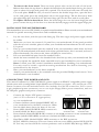
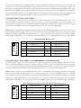
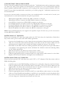
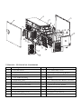
USER’S MANUAL
TITAN550
The high quality of our products is assured by a continuous process of refinement of their
technical features. Therefore, it is possible that your product may differ in some respect from the
descriptions contained in this manual. This is not a problem – it is an improvement. All features,
descriptions, and illustrations contained herein are valid as of the date of publication.
Disclaimer
This manual is intended only as a guide for Antec’s Computer Enclosures. For
more comprehensive instructions on installing your motherboard and peripherals,
please refer to the user’s manuals which come with your components and drives.
TITAN550 – SERVER CASE
Your case includes a pre-installed TruePower 2.0 (TP2-550EPS12V) power supply, one of the quietest
tested power supplies on the market. All TruePower PSUs feature Antec’s Low Noise Technology,
which allows TruePower to deliver an optimum balance between noise reduction and necessary
cooling. The power supply fans will always run at the lowest speed possible for existing load and
conditions. The result? Your power supply will run considerably quieter than traditional power supplies.
Make sure you turn the switch to the ON ( I ) position before you boot up your computer for the
first time. Normally, you won’t need to switch to the OFF (O) position, since the power supply
includes a soft on/off feature. This lets you turn your computer on and off by using the soft
switch on your computer case. If your computer crashes and you can’t shut it down using the soft
switch, you can switch the main power to the OFF (O) position to clear the problem, then reboot.
The Titan has implemented a newly designed double hinge door, which allows the door to open
up to 270º. The front bezel is easy to remove and replace for easy system installation. Titan550 features
6 individual hard drive trays, cooled by two 92mm fans. These drive trays are front accessible to
further ease system integration or upgrading. Additionally, this case also comes with an adjustable
card guide for long add-in cards.
[Applies only to models designed for sale in the European Union: TruePower 2.0 Series
Power Supply models designed for the EU include Power Factor Correction (PFC) circuitry in
accordance with European standard regulation code EN61000-3-2. By altering the input current
wave shape, PFC improves the power factor of the power supply and results in increased energy
efficiency, reduced heat loss, prolonged life for power distribution, and consumption equipment,
and improved output voltage stability.]
SETTING UP
1.
Take the case out of the box. Remove the Styrofoam and the plastic bag. Place the case
upright on a flat, stable surface. The power supply fan should be at the back, facing you.
2.
Note (not applicable to models designed for the European Union): Before installation,
check the red voltage switch setting on the power supply. It should match your local voltage
(115V for North America, Japan, etc. and 230V for Europe and many other countries). If
it doesn’t match, please change the setting. If you don’t you could damage your equipment
and void your warranty.
3.
Remove the thumbscrews from the right side panel. Slide the panel towards the back of
the case to remove the side panel.
4.
Inside the case you should see the power supply, some wiring with marked connectors
(USB, PWR etc.), and installed I/O panel, a power cord and a tool bag containing more
hardware (screws, brass standoffs, etc.), twelve pairs of 3.5" metal drive rails with the rubber
grommets and six pairs of plastic 5.25" drive rails. You need to remove the front bezel in
order to install your 5.25" drives or 3.5" internal drives.
2
5.
6.
To remove the front bezel. There are three plastic tabs on the left side of the bezel.
Release them from the top down to detach the bezel from the metal chassis. Swing the bezel
open to about 90º angle and gently lift it upward. The front bezel will come off easily. Set
it in a safe place. Note: In case you need to remove the double hinge door, open the door
to 90º, and gently press the small plastic tab on the upper hinge. Tilt the door away from
the upper hinge pin, then lift it off the lower hinge pin. Set the door aside in a safe place.
To replace the front bezel door. Place the lower hinge slot over the lower hinge pin and
press or rotate the top of the door in so that the tab fully engages with the upper hinge pin.
INSTALLING THE MOTHERBOARD
This manual does not cover CPU, RAM, or expansion card installation. Please consult your motherboard
manual for specific mounting instructions and troubleshooting.
1.
2.
3.
4.
5.
6.
7.
Lay the case down, with the open side facing up. The drive cages and power supply should
be visible.
Make sure you have the correct I/O panel for your motherboard. If the panel provided
with the case isn’t suitable, please contact your motherboard manufacturer for the correct
I/O panel.
Line up your motherboard with the standoff holes, and remember which holes are lined
up. Not all motherboards will match with all the provided holes; this is normal, and won’t
affect functionally. (In other words, there will likely be extra holes.)
Lift your motherboard away from the standoff holes.
Screw the brass standoffs into the threaded holes that line up with your motherboard. Do
not over tighten the standoffs. Some standoffs may be pre-installed for your convenience.
Note: Consult your CPU cooler’s installation manual before installing your motherboard.
You may need to install a special mounting mechanism first before fastening your
motherboard to the chassis.
Place your motherboard on the brass standoffs.
Attach your motherboard to the standoffs with the provided Phillips-head screws. Your
motherboard is now installed.
CONNECTING THE POWER AND LED
This Antec TruePower 2.0 (TP2-550EPS12V) power supply is an EPS12V compatible power supply
which comes with a configurable 24-pin Main Power Connector, an 8-pin +12V, and a 4-pin +12V
Power Connector for the motherboard. It also includes four SATA connectors, five to seven
4-pin peripheral power connectors, one to two 4-pin Floppy Drive power connectors, and one
PCI Express graphic card power connector.
1.
2.
3.
4.
5.
6.
7.
Picture 2
Connect the 24-pin ATX power connector
Picture 1
(and +12V connectors if appropriate)
to your motherboard.
Connect the Reset switch (labeled RESET SW) to
your motherboard at the RST connector. Make
sure the label always faces the front of the case.
For 24-pin
For 20-pin
Power LED (labeled POWER LED) connector is
motherboards
motherboards
located behind the Reset connector.
Power Switch (labeled POWER SW) connects to the PWR connector on the motherboard.
Speaker (labeled SPEAKER) connector is behind the PWR connector.
Hard Drive LED (labeled H.D.D. LED) connects to the IDE connector.
LED I, LED II connectors: This case comes with two extra LEDs, marked LED I, LED
II. You may use these LED for various purchases such as SCSI LED, Message LED, etc.
3
The power supply is also equipped with a 3-pin fan signal connector. Connect it to one of the fan
connectors on your motherboard. You may monitor the speed of the rear power supply fan
through your motherboard BIOS or through the monitoring software that’s supplied with your
motherboard. Note: At low temperatures, the fan may run as slow as 950 RPM. At these speeds,
some motherboards may not properly detect the fan speed and may generate false warnings of fan
failure. To ensure proper monitoring of the fan, please check your motherboard manual.
CONNECTING THE USB PORTS
You will find a single 10-pin connector on a cable attached to the front USB ports. This is an
Intel standard connector, which is keyed so that it can’t be accidentally, reversed as long as it is
connected to a proper Intel standard motherboard header. Connect the 10-pin connector to your
motherboard headers so that the blocked pin fits over the missing header pin.
Note: Please check your motherboard manual for your USB header pin layout and make sure it
matches the attached table. If it does not match this Intel standard, please call Antec Customer
Support at (800) 22ANTEC (North America) or +31 (0) 10 462-2060 (Europe) for a USB adapter.
This adapter will allow you to connect the front USB to your motherboard on a pin-by-pin basis.
1
9
2
Motherboard Pin Layout
Pin
Signal Names
Pin
Signal Names
1
USB Power 1
2
USB Power 2
3
Negative Signal 1
4
Negative Signal 2
5
Positive Signal 1
6
Positive Signal 2
7
Ground 1
8
Ground 2
9
Key (No Pin)
10
Empty Pin
10
CONNECTING THE IEEE 1394 (FIREWIRE®, I.LINK®) PORT
You will find a single 10-pin connector on a cable attached to the front IEEE 1394 connection.
This is an Intel standard connector, which is keyed so that it can’t be accidentally reversed as long
as it is connected to a proper Intel standard motherboard header. Connect the 10-pin connector
to your motherboard header so that the blocked pin fits over the missing header pin.
Note: Please check your motherboard manual for your IEEE 1394 header pin layout and make
sure it matches the attached table. If you intend to connect the front FireWire port to an IEEE
1394 add-on card that comes with an external-type IEEE 1394 connector, please call Antec Customer
Support at (800) 22ANTEC (North America) or +31 (0) 10 462-2060 (Europe) for an adapter.
This adapter will allow you to connect the front IEEE 1394 port to the external-type connector.
1
9
2
Pin Assignment for Front Panel IEEE 1394 Connector
Pin
Signal Names
Pin
Signal Names
1
TPA+
2
TPA–
3
Ground
4
Ground
5
TPB+
6
TPB–
7
+12V
8
+12V
9
Key (No Pin)
10
Ground
10
4
CONNECTING THE AUDIO PORTS
There is an Intel standard 10-pin connector (with also 7 individual wires with connectors) coming
out from the front panel speaker and microphone connection. If your motherboard supports
Intel’s standard onboard audio connector, you can plug in the 10-pin connector directly onto the
board. For non-Intel standard audio connection, you need to plug the 7 individual connectors into
the motherboard.
Locate the internal audio connectors from your motherboard or sound card. Consult your
motherboard or sound card manual for the pin-out positions.
1.
2.
3.
4.
5.
6.
7.
Microphone Signal Pin: Connect the MIC connector to this pin.
Microphone Power: Connect the MIC-BIAS connector to this pin.
Ground Pin: Connect the AUD GND connector to this pin.
Front Right Speaker Out Pin: Connect the FPOUT-R connector to this pin.
Front Left Speaker Out Pin: Connect to the FPOUT-L connector to this pin.
Rear Right Speaker Out Pin: Connect to the RET-R connector to this pin.
Rear Left Speaker Out Pin: Connect the RET-L connector to this pin.
Note: Your motherboard may not support rear speaker output. In this case, you do not need to
connect RET-R and RET-L.
INSTALLING 3.5" DEVICES
There are six internal 3.5" drive bays right under the 5.25" drive bays for hard drives. Each drive
bay comes with a pair of drive rails with rubber grommets.
1.
2.
3.
4.
5.
6.
7.
Unscrew the thumbscrews on the 92mm fan mount bracket. Open the fan mount bracket.
Take two of the drive rails and mount them to the sides of the 3.5" device. Make sure the
metal portion is angled on the outside and facing towards the front of the device.
Both sides of the drive rails have rubber grommets with the special screws provided. Don’t
over-tighten. Over tightening the screws will harm the vibration and noise reducing ability
of the rubber grommets.
Slide the device into the drive bay until you hear a click.
Repeat the same procedure for the other devices as necessary.
Find the appropriate power connector (SATA or 4 pin molex) and connect it to the drive.
Replace the fan mount bracket and tighten the thumbscrews.
INSTALLING THE 5.25" DEVICES
There are four external 5.25" drive bays (one with 5.25" to 3.5" Adapter). Each bay comes with an
EMI shielding plate.
1.
2.
3.
4.
5.
6.
Carefully remove the EMI Shielding and keep it in a safe place. You may need it in future.
Take two plastic drive rails and mount them to the sides of the 5.25" device. Make sure the
angled end of the drive rail is towards the front of the drive and that the angle opens out.
Slide the device into the drive bay until you hear a click.
Mount the other devices accordingly.
Find the appropriate power connector (SATA or 4 pin Molex) and connect it to the drive.
After you have finished the installation, carefully use your thumbs to push the plastic drive
bay covers off the bezel. Like the metal plates, take off only the covers for the drive bays
you are using now. Attach the bezel back onto the case.
5
To install a floppy or other external 3.5" device to the 5.25" to 3.5" Adapter:
1.
2.
3.
Slide the adapter out.
Place the drive in the adapter and fasten it with the screws provided.
Find a 4-pin floppy power connector on the power supply and connect it to the male 4-pin
connector on the devices.
COOLING SYSTEM
The case has one 120mm Tricool fan installed in the rear. Two optional 92mm fan mounts may
be found right behind the front bezel.
Rear Fan: The installed 120mm TriCool fan has a three-speed switch that lets you choose between
quiet, performance, or maximum cooling. See specifications below. The fan is installed so that the
air is blowing out of the case. Connect a large 4-pin connector from the power supply to the male
4-pin connector on the fan.
Note: The minimum voltage to start the fan is 5V. We recommend our users to set the fan speed
to High if you choose to connect the fan to a fan control device or to the Fan-Only connector
found on some Antec power supplies. A fan-control-device regulates the fan speed by varying the
voltage to it. The voltage may start as low as 4.5 V to 5V. The already lowered voltage from the
fan control device will then be further reduced by the TriCool circuitry below 5V, and the fan may
not be able to start. Setting the fan speed to High should avoid this problem.
Specifications:
Size:
Rated Voltage:
120 x 120 x 25.4 mm
DC 12V
Speed
Input
Current
Air Flow
Static
Pressure
Acoustical
Noise
Input
Power
High
2000 RPM
0.24A
(Max.)
2.24 m³/min.
(79 CFM)
2.54 mm-H2O
(0.10 inch-H2O)
30 dBA
2.9 W
Medium
1600 RPM
0.2A
1.59 m³/min.
(56 CFM)
1.53 mm-H2O
(0.06 inch-H2O)
28 dBA
2.4 W
Low
1200 RPM
0.13A
1.1 m³/min.
(39 CFM)
0.92 mm-H2O
(0.04 inch-H2O)
25 dBA
1.6 W
Front Fans: You can install two 92mm fans in front of the internal 3.5" drives. These fans must
be installed so that the air is blowing into the case. We recommend using Antec 92mm TriCool
fans to balance quiet performance with maximum cooling. See our web site for product information.
Note: Please choose your fan speed wisely. In most cases, a medium or even low speed setting will
be enough to supply adequate cooling.
6
TITAN550 – TECHNICAL DIAGRAMS
No.
1
2
3
4
5
6
7
8
9
10
11
Description
Left Side Panel
Expansion Slot Cover
Top Panel
5.25" EMI Shielding
HDD Drive Rail
5.25" to 3.5" Adapter (Sheet Metal)
I/O Port PCB Assembly
Right Side Panel
Front Bezel
5.25" Drive Bay Cover
5.25" to 3.5" Adapter Cover
No.
12
13
14
15
16
17
18
19
20
21
22
Description
3.5" Drive Bay Cover
Front Bezel Mounting Bracket
Front Door
Hinge
3.5" Drive Rail with Rubber Grommet
Bottom panel
92mm Front Fan Holder
Thumbscrews
PCI Long Card Holder
Expansion Slot Shield
Rear Vent Cover
TITAN550 - DIAGRAMMES TECHNIQUES
No.
1
2
3
4
5
6
7
8
9
10
11
Description
Panneau gauche
Couvercle de logements d'extension
Panneau supérieur
Blindage EMI 5,25 pouces
Rail de lecteur HDD
Adaptateur 5,25/3,5 pouces (tôle)
Carte de circuits imprimés à port E/S
Panneau droit
Collerette d'encastrement avant
Couvercle de baie d'unité de 5.25 pouces
Couvercle de l'adaptateur 5,25/3,5 pouces
No.
12
Description
Couvercle de baie d'unité de 3,5 pouces
13
Support de fixation de la collerette d'encastrement avant
14
15
Porte avant
Charnière
16
Rail de lecteur de 3,5 pouces avec œillet en caoutchouc
17
Panneau du bas
Support de ventilateur avant 92 mm
Vis à oreilles
Long porte-carte PCI
Couvercle de logement d'extension
Couvercle d'évent arrière
18
19
20
21
22
TITAN550 - TECHNISCHE ZEICHNUNGEN
Nummer
1
2
3
4
5
6
7
8
9
10
11
Beschreibung
Linke Seitenabdeckung
Abdeckung des Erweiterungssteckplatzes
Obere Abdeckung
5,25" EMI-Abschirmung
HDD-Laufwerkschiene
5,25"-zu-3,5"-Adapter (Blech)
E/A-Port PCB-Baugruppe
Rechte Seitenabdeckung
Frontrahmen
5,25" Laufwerkabdeckung
5,25"-zu-3,5"-Adapterabdeckung
Nummer
12
13
14
15
16
17
18
19
20
21
22
Beschreibung
3,5" Laufwerkabdeckung
Frontrahmenklammer
Vordertür
Scharnier
3,5" Laufwerkschiene mit Gummiunterlage
Stellfläche
Halterung für 92 mm Frontlüfter
Rändelschrauben
PCI-Langkartenhalter
Abschirmung für Erweiterungssteckplatz
Abdeckung für rückwärtigen Lüftungsschlitz
TITAN550 - DIAGRAMMI TECNICI
N.
N.
Descrizione
12
Copertura della guida di fissaggio per unità da 3,5"
13
Staffa di montaggio per pannello anteriore
14
15
Sportello anteriore
Cerniera
16
Binario per unità a disco da 3,5" con gommini antiurto
17
9
Descrizione
Pannello laterale sinistro
Coperchio dello slot di espansione
Pannello superiore
Schermatura EMI per unità da 5,25"
Binario per unità a disco HDD
Adattatore da 5,25" a 3,5" (lamiera)
Insieme PCB porte I/O
Pannello laterale destro
Pannello anteriore
10
Copertura della guida di fissaggio per unità da 5,25"
21
11
Copertura adattatore da 5,25" a 3,5"
22
Pannello inferiore
Supporto ventola anteriore da 92 mm
Viti ad alette
Supporto scheda PCI lunga
Schermatura slot di espansione
Copertura presa d'aria posteriore
Nº
Descripción
12
Cubierta de alojamientos de unidades de 3,5"
13
6
Descripción
Panel izquierdo
Tapa de ranura de expansión
Panel superior
Blindaje EMI de 5,25"
Guías de unidad de disco duro
Adaptador de 5,25" a 3,5" (hoja de metal)
7
Conjunto de placa de circuito impreso de puertos de E/S
18
8
Panel derecho
Marco frontal
19
9
10
Cubierta de alojamientos de unidades de 5,25"
21
11
Cubierta de adaptador de 5,25" a 3,5"
22
Soporte de montaje del marco frontal
Puerta frontal
Bisagra
Guía de unidad de 3,5" con aros de goma
Panel inferior
Soporte de ventilador frontal de 92 mm
Tornillos de apriete manual
Soporte para tarjetas PCI largas
Blindaje de ranura de expansión
Cubierta de ventilación trasera
1
2
3
4
5
6
7
8
18
19
20
TITAN550 - DIAGRAMAS TÉCNICOS
Nº
1
2
3
4
5
14
15
16
17
20
Antec, Inc.
47900 Fremont Blvd.
Fremont, CA 94538
Tel: 510-770-1200
Fax: 510-770-1288
Antec Europe B.V.
Sydneystraat 33
3047 BP Rotterdam
The Netherlands
Tel: +31 (0) 10 462-2060
Fax: +31 (0) 10 437-1752
Technical Support
US & Canada
1-800-22ANTEC
[email protected]
Europe
+31 (0) 10 462-2060
[email protected]
www.antec.com
© Copyright 2005 Antec, Inc. All rights reserved. All trademarks are the property of their respective owners.
Reproduction in whole or in part without written permission is prohibited. Printed in China.
Version 1.0.5 2/02/2005