1
5.
6.
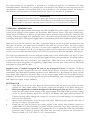
To remove the front bezel. There are three plastic tabs on the left side of the bezel.
Release them from the top down to detach the bezel from the metal chassis. Swing the bezel
open to about 90º angle and gently lift it upward. The front bezel will come off easily. Set
it in a safe place. Note: In case you need to remove the double hinge door, open the door
to 90º, and gently press the small plastic tab on the upper hinge. Tilt the door away from
the upper hinge pin, then lift it off the lower hinge pin. Set the door aside in a safe place.
To replace the front bezel door. Place the lower hinge slot over the lower hinge pin and
press or rotate the top of the door in so that the tab fully engages with the upper hinge pin.
INSTALLING THE MOTHERBOARD
This manual does not cover CPU, RAM, or expansion card installation. Please consult your motherboard
manual for specific mounting instructions and troubleshooting.
1.
2.
3.
4.
5.
6.
7.
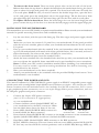
Lay the case down, with the open side facing up. The drive cages and power supply should
be visible.
Make sure you have the correct I/O panel for your motherboard. If the panel provided
with the case isn’t suitable, please contact your motherboard manufacturer for the correct
I/O panel.
Line up your motherboard with the standoff holes, and remember which holes are lined
up. Not all motherboards will match with all the provided holes; this is normal, and won’t
affect functionally. (In other words, there will likely be extra holes.)
Lift your motherboard away from the standoff holes.
Screw the brass standoffs into the threaded holes that line up with your motherboard. Do
not over tighten the standoffs. Some standoffs may be pre-installed for your convenience.
Note: Consult your CPU cooler’s installation manual before installing your motherboard.
You may need to install a special mounting mechanism first before fastening your
motherboard to the chassis.
Place your motherboard on the brass standoffs.
Attach your motherboard to the standoffs with the provided Phillips-head screws. Your
motherboard is now installed.
CONNECTING THE POWER AND LED
This Antec TruePower 2.0 (TP2-550EPS12V) power supply is an EPS12V compatible power supply
which comes with a configurable 24-pin Main Power Connector, an 8-pin +12V, and a 4-pin +12V
Power Connector for the motherboard. It also includes four SATA connectors, five to seven
4-pin peripheral power connectors, one to two 4-pin Floppy Drive power connectors, and one
PCI Express graphic card power connector.
1.
2.
3.
4.
5.
6.
7.
Picture 2
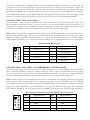
Connect the 24-pin ATX power connector
Picture 1
(and +12V connectors if appropriate)
to your motherboard.
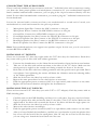
Connect the Reset switch (labeled RESET SW) to
your motherboard at the RST connector. Make
sure the label always faces the front of the case.
For 24-pin
For 20-pin
Power LED (labeled POWER LED) connector is
motherboards
motherboards
located behind the Reset connector.
Power Switch (labeled POWER SW) connects to the PWR connector on the motherboard.
Speaker (labeled SPEAKER) connector is behind the PWR connector.
Hard Drive LED (labeled H.D.D. LED) connects to the IDE connector.
LED I, LED II connectors: This case comes with two extra LEDs, marked LED I, LED
II. You may use these LED for various purchases such as SCSI LED, Message LED, etc.
3