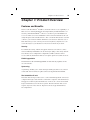
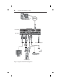
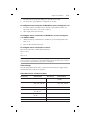
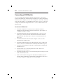
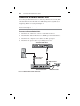
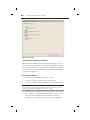
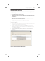
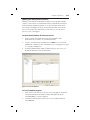
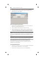
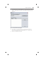
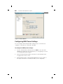
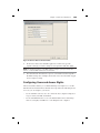
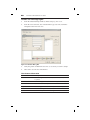
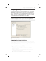
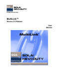
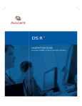
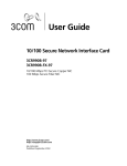
1
SwitchView™ IP Installer/User Guide SwitchView™ IP Installer/User Guide Avocent, the Avocent logo, The Power of Being There, OSCAR, KVM OVER IP and SwitchView are trademarks or registered trademarks of Avocent Corporation or its affiliates. All other marks are the property of their respective owners. © 2003 Avocent Corporation. All rights reserved. USA Notification Warning: Changes or modifications to this unit not expressly approved by the party responsible for compliance could void the user's authority to operate the equipment. Note: This equipment has been tested and found to comply with the limits for a Class B digital device, pursuant to Part 15 of the FCC Rules. These limits are designed to provide reasonable protection against harmful interference in a residential installation. This equipment generates, uses and can radiate radio frequency energy and, if not installed and used in accordance with the instructions, may cause harmful interference to radio communications. However, there is no guarantee that interference will not occur in a particular installation. If this equipment does cause harmful interference to radio or television reception, which can be determined by turning the equipment off and on, the user is encouraged to try to correct the interference by one or more of the following measures: • • • Reorient or relocate the receiving antenna. Increase the separation between the equipment and receiver. Connect the equipment into an outlet on a circuit different from that to which the receiver is connected. • Consult the dealer or an experienced radio/TV technician for help. Canadian Notification This Class B digital apparatus complies with Canadian ICES-003. Cet appareil numérique de la classe B est conforme à la norme NMB-003 du Canada. Agency Approvals FCC part 15B, EN55022, EN55024, EN61000-3-3 Table of Contents Chapter 1: Product Overview Features and Benefits . . . . . . . . . . . . . . . . . . . . . 3 Safety Precautions . . . . . . . . . . . . . . . . . . . . . . . 5 Chapter 2: Installation Getting Started . . . . . . . . . . . . . . . . . . . . . . . . . . 9 Mouse Acceleration. . . . . . . . . . . . . . . . . . . . . . 10 Installing the SwitchView IP . . . . . . . . . . . . . . 12 Connecting a KVM Switch . . . . . . . . . . . . . . . 14 Connecting a Remote Reboot Unit . . . . . . . . . 16 Connecting a USB Keyboard and Mouse . . . . 17 Setting the IP Address . . . . . . . . . . . . . . . . . . . 18 Using ARP to Set the IP Address . . . . . . . . . . . 18 Using DHCP to Obtain the IP Address . . . . . . 19 Accessing Through a Firewall . . . . . . . . . . . . 20 Launching the SwitchView IP Web Server and Viewer . . . . . . . . . . . . . . . . . . . . . . . . . . . . 21 Understanding the Status LEDs . . . . . . . . . . . 23 Restoring Factory Default Settings . . . . . . . . . 23 Chapter 3: Operations Using the SwitchView IP Viewer. . . . . . . . . . . 27 Working with Log Files . . . . . . . . . . . . . . . . . . 29 Maintaining the Environment . . . . . . . . . . . . 30 Chapter 4: Advanced Configuration Modifying the Configuration . . . . . . . . . . . . . 37 Configuring RRU Power Settings . . . . . . . . . . 38 Configuring Users and Access Rights . . . . . . . 39 Configuring Security . . . . . . . . . . . . . . . . . . . . 41 Replacing the Server Certificate. . . . . . . . . . . . 41 Appendices Appendix A: Technical Specifications. . . . . . . 45 Appendix B: Technical Support. . . . . . . . . . . . 47 Appendix C: Troubleshooting . . . . . . . . . . . . . 48 Appendix D: RRU and Console Pinouts . . . . 50 1 Product Overview Contents Features and Benefits . . . . . . . . . . . . . . . . 3 Safety Precautions . . . . . . . . . . . . . . . . . . 5 Chapter 1: Product Overview 3 Chapter 1: Product Overview Features and Benefits The Avocent SwitchView ™ IP adds economical remote access capability to a PS/2 server or existing KVM switch. Using industry standard TCP/IP connectivity, this KVM OVER IP TM remote access device provides BIOS level access to a PS/2 server via standard IP connection. The SwitchView IP can easily integrate with a KVM switch to offer convenient IP-based access and control to your IT environment. With the secure browser-based access of SwitchView IP, you can control your servers anywhere, anytime. You can even remotely boot your business-critical servers from any location. Security For enhanced security, 128 bit encryption ensures secure remote connections via industry standard Secure Sockets Layer (SSL) connectivity. SwitchView IP also eases configuration complexities. Unlike software remote access solutions, SwitchView IP does not require agents for each host server. FLASH upgradable The SwitchView IP is FLASH upgradable for fast and easy updates via the Avocent web site. System log A system log enables you to track user login and logout, file access, critical events and other activities. Log files can be saved, printed and emailed. The SwitchView IP unit The SwitchView IP provides secure control and management of the host computer through a web interface and client computer. The SwitchView IP supports a PS/2 keyboard and mouse on the local console and a USB keyboard and mouse for the host system. The SwitchView IP does not require any host video drivers. Figure 1.1 shows a typical SwitchView IP configuration. 4 SwitchView IP Installer/User Guide SwitchView IP Client SwitchView IP Front View Rear View 12 v Power Adaptor Mouse Keyboard Monitor Host Computer Figure 1.1: Typical SwitchView IP Configuration Chapter 1: Product Overview 5 The Keyboard, Video, Mouse (KVM) cable The KVM cable redirects keyboard, video and mouse input from the host computer to the SwitchView IP. 12 volt power adaptor The 12 volt (v) power adaptor provides power to the SwitchView IP unit. Safety Precautions To avoid potential video and/or keyboard problems when using Avocent products: • If the building has 3-phase AC power, ensure that the server and monitor are on the same phase. For best results, they should be on the same circuit. To avoid potentially fatal shock hazard and possible damage to equipment, please observe the following precautions: • Do not use a 2-wire extension cord in any Avocent product configuration. • Test AC outlets at the server and monitor for proper polarity and grounding. • Use only with grounded outlets at both the server and monitor. When using a backup Uninterruptible Power Supply (UPS), power the server, the monitor and the SwitchView IP off the supply. 6 SwitchView IP Installer/User Guide 2 Installation Contents Getting Started . . . . . . . . . . . . . . . . . . . . . . . . . . 9 Mouse Acceleration. . . . . . . . . . . . . . . . . . . . . . 10 Installing the SwitchView IP . . . . . . . . . . . . . . 12 Connecting a KVM Switch . . . . . . . . . . . . . . . 14 Connecting a Remote Reboot Unit . . . . . . . . . 16 Connecting a USB Keyboard and Mouse . . . . 17 Setting the IP Address . . . . . . . . . . . . . . . . . . . 18 Using ARP to Set the IP Address . . . . . . . . . . . 18 Using DHCP to Obtain the IP Address . . . . . . 19 Accessing Through a Firewall . . . . . . . . . . . . 20 Launching the SwitchView IP Web Server and Viewer . . . . . . . . . . . . . . . . . . . . . . . . . . . . 21 Understanding the Status LEDs . . . . . . . . . . . 23 Restoring Factory Default Settings . . . . . . . . . 23 Chapter 2: Installation 9 Chapter 2: Installation Getting Started Before installing your SwitchView IP, refer to the following lists to ensure that you have all the items necessary for proper installation. Supplied with the SwitchView IP • SwitchView IP unit • KVM cable • 12 v power adaptor Requirements The SwitchView IP supports many hardware and software configurations for host and client computers. Make sure that your computers meet the following software and hardware requirements. Host computer operating systems • Microsoft Windows NT 4 • Microsoft Windows XP • Microsoft Windows 2000 • Microsoft Windows 98 SE • Microsoft Windows ME • Red Hat Linux 8.0 • Novell NetWare v6.0 Host computer hardware configuration • The video adaptor is non-interlaced and is set to a supported video resolution and refresh rate. For more information, see Video settings later in this chapter. • Mouse acceleration should be turned off. NOTE: The SwitchView IP Viewer mouse movement is slow or erratic when mouse acceleration is not turned off. For more information, see Mouse Acceleration in this chapter and Appendix C. 10 SwitchView IP Installer/User Guide Client computer operating systems • Microsoft Windows NT 4 • Microsoft Windows XP • Microsoft Windows 2000 • Microsoft Windows 98 SE • Microsoft Windows ME Client computer web browser The required web browser for the client computer is Microsoft Internet Explorer 5.5 or higher. Client computer hardware configuration • 500 Mhz / Intel Pentium III processor or greater • 256 Mb RAM or greater • 2 Mb free local hard drive space or greater Mouse Acceleration The following steps describe how to configure mouse acceleration settings for the supported operating system platforms. NOTE: SwitchView IP Viewer mouse movement is slow and erratic when mouse acceleration is not turned off. For more information, see Appendix C. To configure mouse acceleration on Windows XP: 1. From the Control Panel, click the Printers and Other Hardware option and then the Mouse icon. 2. From the Mouse Properties dialog box, click the Pointer Option tab. 3. Center the Motion pointer speed slider bar and deselect the Enhance Pointer Precision option. To configure mouse acceleration on Windows 2000 and Windows 98 ME: 1. From the Control Panel, click the Mouse icon. 2. From the Mouse Properties dialog box, click the Motion tab. 3. Center the Speed slider bar and set Acceleration to None. To configure mouse acceleration on Windows 98 SE and Windows NT4: 1. From the Control Panel, click the Mouse icon. Chapter 2: Installation 2. From the Mouse Properties dialog box, click the Motion tab. 3. Set the Pointer speed slider bar completely to the left. 11 To configure mouse acceleration on NetWare 6 servers running Java 1.4.1: 1. From the NetWare 6 Graphical User Interface (GUI) Environment tool Input tab, select Turn off mouse acceleration. 2. Click Apply and restart the GUI. To configure mouse acceleration on NetWare 6 servers running Java 1.3.1 CSP8 or CSP9: 1. Add the following command to the NetWare 6 sys:/java/nwgfx/xinitrc file: xset m 1 2. Save the file and restart the GUI. To configure mouse acceleration on Linux: Execute the following command line parameter: xset 0 255 -orxset m 0 NOTE: If the host computer is running an operating system that does not support turning off mouse acceleration, you will need to set the SwitchView IP Viewer Auto Mouse Sync to Off. For more information on the Auto Mouse Sync feature, see Chapter 3. Video settings The following table lists the video resolutions and refresh rates supported by the SwitchView IP on the host computer. Video Resolutions and Refresh Rates Resolutions Refresh Rates Resolutions Refresh Rates 512 x 384 70 Hz 720 x 400 60, 70, 75, 85, 100 Hz* 640 x 480 60, 67, 72, 75, 85, 90, 100*, 120*, 140* Hz 800 x 600 56, 60, 72, 75, 85, 90, 100*, 120*, 140* Hz 832 x 624 75 Hz 960 x 720 60, 75, 85 Hz 1024 x 768 60, 70, 75, 80, 85, 90*, 100* Hz 1024 x 800 60 Hz 1152 x 864 60, 70, 75, 76, 80, 85* Hz 1152 x 870 75 Hz 1152 x 900 67 Hz 1280 x 960 60, 75*, 85* Hz 1280 x 1024 60, 67*, 75*, 85* Hz 12 SwitchView IP Installer/User Guide NOTE: *These refresh rates may not provide the best video lock on all video cards. For best performance, use the lowest refresh rate for any of the resolutions listed. Installing the SwitchView IP Follow these instructions to connect the SwitchView IP unit to a host computer and to a KVM switch. Refer to Figure 2.1 for port locations and cabling connections. To connect the SwitchView IP to a host computer: 1. From the host computer, disconnect the video cable from the Video port and attach it to the Video Out port on the back of the SwitchView IP. 2. Disconnect the mouse and keyboard from the host computer and reconnect them to the corresponding ports on the back of the SwitchView IP. 3. Attach the green KVM cable mouse connector to the host computer Mouse port. 4. Attach the purple KVM cable keyboard connector to the host computer Keyboard port. 5. Attach the blue KVM cable male video connector to the host computer Video port. 6. Attach the black KVM cable computer connector to the Computer port on the back of the SwitchView IP. 7. Attach the black KVM cable female video connector to the Video In port on the back of the SwitchView IP. 8. Attach the SwitchView IP to your network using a 10/100 Ethernet cable connected through the Network port on the front of the SwitchView IP. 9. Connect the 12 v power adaptor to the Power port of the SwitchView IP and to a grounded power source. The SwitchView IP unit is now installed and powered. Chapter 2: Installation SwitchView IP Client SwitchView IP Front View Rear View 12 v Power Adaptor Mouse Keyboard Monitor Host Computer Figure 2.1: Connection of SwitchView IP to Host Computer 13 14 SwitchView IP Installer/User Guide Connecting a KVM Switch You can configure the SwitchView IP with a KVM switch to pass the keyboard, video and mouse output through a web browser. Using a SwitchView IP Viewer client computer, you can control computers connected to the KVM switch. For information on compatible KVM switches contact Avocent. Refer to Figure 2.2 and the following instructions to connect a KVM switch to the SwitchView IP. To connect a KVM switch: 1. Attach the computers to a KVM switch as outlined in the KVM manufacturer documentation. Set the KVM switch to pass output to a computer you want to control. 2. Attach the black SwitchView IP cable female video connector to the Video In port on the back of the SwitchView IP and attach the blue SwitchView IP cable male video connector to the KVM switch local video port. 3. Attach the black SwitchView IP cable computer connector to the SwitchView IP Computer port. 4. Attach the purple SwitchView IP cable keyboard connector and green mouse connector to the KVM switch local keyboard and mouse ports. 5. Attach a keyboard and mouse directly to the SwitchView IP Keyboard and Mouse ports. 6. Attach a monitor by connecting the monitor video cable to the SwitchView IP Video Out port. 7. Attach the SwitchView IP to your network using the Network port on the front of the SwitchView IP. 8. From a client web browser, type the SwitchView IP address, log in to the SwitchView IP Web Server and launch the SwitchView IP Viewer to access the computer configured to receive KVM input. Chapter 2: Installation SwitchView IP Client SwitchView IP Front View Rear View Mouse Keyboard KVM Switch Monitor Computers Figure 2.2: Connection of SwitchView IP to KVM Switch 15 16 SwitchView IP Installer/User Guide Connecting a Remote Reboot Unit This section provides instructions for connecting a Remote Reboot Unit (RRU) to the SwitchView IP. For information on RRU settings and configuration, see Configuring RRU Power Settings in Chapter 4. NOTE: The SwitchView IP supports many off-the-shelf RRU units. For more information, contact Avocent Technical Support. To connect a Remote Reboot Unit: 1. Attach the RRU cable serial connector to the RRU serial port. 2. Attach the RRU cable RJ-12 connector to the RRU port of the SwitchView IP. 3. Attach the host computer power cable to the RRU power port. 4. Attach the RRU power cable to a grounded power source. SwitchView IP Rear View RRU Cable Computer Host Computer Power Cable RRU Serial Port Power Source Remote Reboot Unit Figure 2.3: Remote Reboot Unit Connection RRU Power Cable Chapter 2: Installation 17 Connecting a USB Keyboard and Mouse The instructions in this section and Figure 2.4 provide information for connecting a USB keyboard and mouse to the SwitchView IP. To connect a USB keyboard and mouse: 1. Obtain a USB A/B cable (not included) and attach the type A connector to the USB port on the host computer. 2. Attach the USB cable type B connector to a USB port on the SwitchView IP. 3. Attach the USB keyboard connector to another USB port on the host computer. 4. Attach the USB mouse connector to the USB port on the keyboard or on the host computer. SwitchView IP Front View Rear View External Switch USB Cable Host Computer USB Keyboard Figure 2.4: USB Keyboard and Mouse Connection USB Mouse 18 SwitchView IP Installer/User Guide Setting the IP Address This section provides instructions for setting the IP address for the SwitchView IP. Using the static IP address The SwitchView IP boots to the following default static IP address, gateway and netmask: • IP address: 192.168.1.254 • Gateway: 192.168.1.1 • Netmask: 255.255.255.0 You can use the SwitchView IP on a subnet that matches the default static IP address or use the SwitchView IP Web Server Network window to change the IP address. For information on changing the IP address, see Modifying the Configuration in Chapter 4. Using ARP to Set the IP Address You can use Address Resolution Protocol (ARP), a command line utility included with most operating system platforms, to set the IP address for the SwitchView IP. Follow these instructions to set the IP address using ARP. NOTE: As a security feature, ARP only runs when the system boots to the default IP address of 192.168.1.254. Once ARP has been used to move the appliance from this address, ARP is turned off. The only way to get ARP to run again is to set the IP address to the default and reboot the system. To run ARP and set the IP address: 1. Contact your network administrator and obtain an IP address. 2. From a client computer attached to the same subnet as the SwitchView IP, open a DOS window and enter the following command: arp –s <ip address> <mac address> Replace <ip address> with the IP address obtained from your network administrator, and <mac address> with the 12 digit MAC address listed on the SwitchView IP (for example, 00-05-C2-1E-40-20). 3. Ping the SwitchView IP by entering the following command: Ping <IP Address> NOTE: During verification of the IP address, the message host not responding may display. If this message displays four times, the IP or MAC address is incorrect. Chapter 2: Installation 4. 19 If the Ping command was successful, remove the IP address from the ARP table using the following command: arp –d <IP Address> -orIf the Ping command failed, verify the IP and MAC address and resolve any communication issues. Using DHCP to Obtain the IP Address If Dynamic Host Configuration Protocol (DHCP) services are available on the local subnet where the SwitchView IP is installed, use the following instructions to configure the SwitchView IP to use DHCP to automatically obtain the IP address. To use DHCP to obtain the IP address: 1. In the web browser Address bar of a client computer, enter the IP address of the SwitchView IP and click Enter. 2. In the Enter Network Password dialog box, type admin (default username) and password (default password) and click OK. Figure 2.5: Enter Network Password Dialog Box 3. From the Global Settings window, under Category, click Network. 4. From the Network window, select the Use DHCP option and click Apply. 20 SwitchView IP Installer/User Guide Figure 2.6: Network Window 5. The SwitchView IP will automatically obtain an IP address from DHCP services and use it as the SwitchView IP address. The previous IP address is stored until the Set Static IP option is enabled. To disable DHCP configuration: 1. In the web browser Address bar of a client computer, enter the IP address of the SwitchView IP and click Enter. 2. In the Enter Network Password dialog box, type admin (default username) and password (default password) and click OK. 3. From the Global Settings window, under Category, click Network. 4. Select the Set Static IP option and use the previous IP address, gateway and subnet mask settings, or enter new IP address information and click Apply. 5. Log in to the static IP address and the SwitchView IP Web Server will refresh with the new IP address. Accessing Through a Firewall Before attempting to access the SwitchView IP through a firewall, verify that the following Internet ports are available and configured for Transmission Control Protocol (TCP) traffic or packets. Chapter 2: Installation 21 Internet Ports Applications / Services Ports (decimal) SwitchView IP Viewer 5900 Update.exe 12296 HTTP 80 SSL 443 Telnet 23 FTP 21 Launching the SwitchView IP Web Server and Viewer Complete the setup process by launching the SwitchView IP Web Server and Viewer. Using the SwitchView IP Web Server, you can communicate directly with the SwitchView IP on the host computer. For more detailed information, refer to Chapter 4. To launch the SwitchView IP Web Server: 1. From a client computer, launch a web browser. 2. In the web browser Address bar, type the IP address of the SwitchView IP and click Enter. 3. In the Enter Network Password dialog box, type admin (default username) and password (default password) and click OK. The username and password are case sensitive. In the Network window, you can change the default admin password, add users and assign access rights by clicking Users under Category. After modifying a user’s information, click Apply to save changes. For information on modifying the SwitchView IP initial setup configuration, see Modifying the Configuration in Chapter 4. 4. From the Global Settings window, under Category, click Network to change the host name or SwitchView IP name. 5. Click the Tools tab and select Set Appliance Date and Time to set the current time and date. Click Apply to save any changes. 22 SwitchView IP Installer/User Guide Figure 2.7: Tools Tab Launching the SwitchView IP Viewer After setting the IP address and completing the setup process, you can launch the SwitchView IP Viewer from the SwitchView IP Web Server and verify that the remote client can communicate with the host computer. For more information on viewing and controlling computers, see Chapter 3. To launch the Viewer: 1. From the Network window, click Connect Video. 2. Accept the security certificate, if one is presented. 3. If you are prompted, enter the IP address of the SwitchView IP. NOTE: For Microsoft Internet Explorer 5.5 SP2, 6.0 and 6.1, the IP address is automatically passed through to the SwitchView IP. If you are running an earlier version of Internet Explorer, update it to version 5.5 or later. 4. From the SwitchView IP Viewer screen, you now can view the host computer, control its keyboard and mouse and execute tasks. For more information on viewing and controlling computers, see Using the SwitchView IP Viewer in Chapter 3. Chapter 2: Installation 23 Understanding the Status LEDs The following table lists the SwitchView IP status LEDs and their states when illuminated. LED Name and Status LED Name LED On Remote Session SwitchView IP Viewer session active Power SwitchView IP powered Ready SwitchView IP internal system running Error SwitchView IP internal error (contact Avocent Technical Support) Restoring Factory Default Settings You can restore the SwitchView IP factory default settings by depressing the external switch for one second. The external switch is located next to the Power port on the back of the device, as shown in Figure 2.4. This switch is not a reset switch, and data is not preserved. 24 SwitchView IP Installer/User Guide 3 Operations Contents Using the SwitchView IP Viewer . . . . . . . . . . 27 Working with Log Files . . . . . . . . . . . . . . . . . . 29 Maintaining the Environment . . . . . . . . . . . . 30 Chapter 3: Operations 27 Chapter 3: Operations Using the SwitchView IP Viewer The SwitchView IP Viewer enables users to view and control a host computer from any location using a standard TCP/IP connection and web browser. The following tables outline features and commands you can execute remotely, using the SwitchView IP Viewer drop-down menus. Using the SwitchView IP Viewer shortcuts The SwitchView IP Viewer Shortcuts drop-down menu provides quick access to the following common keystrokes and commands to help you manage and control your SwitchView IP Viewer environment. SwitchView IP Viewer Shortcuts Menu Command Does This Crtl-Alt-Del Executes Ctrl-Alt-Del command Start Menu Enables access to Windows Start menu programs and files Task Manager Enables access to Windows Task Manager Close Window Closes current window Close MDI Window Closes a Multi-Document Interface (MDI) frame or pop-up window Scroll Lock x 2 Used with KVM switch Next Window Moves focus to one of the open windows Print Screen Copies current SwitchView IP Viewer screen data to copy buffer Print Window Copies current window to printer Hold Down Ctrl Key Used with KVM switch Hold Down Alt Key Used with KVM switch Exit SwitchView IP Viewer Client Closes SwitchView IP Viewer and remote session Using the SwitchView IP Viewer options The SwitchView IP Viewer Options drop-down menu provides access to the following additional settings to help you fine-tune your SwitchView IP Viewer environment. 28 SwitchView IP Installer/User Guide SwitchView IP Viewer Options Menu Command Description Force Screen Refresh Refreshes screen to original quality. Toggle Full Screen Toggles screen size. Viewer Options Phase settings. Enables you to select quality of video allowing higher speed video performance. There is also a setting for horizontal and vertical screen alignments. Auto Mouse Sync Synchronizes mouse movements of the host computer and the VP Viewer. The default and recommended setting is On. Set the Auto Mouse Sync to Off only if the host computer operating system does not provide an option to turn off mouse acceleration. For more information on configuring mouse acceleration and erratic mouse movements, see Chapter 2 and Appendix A. Show frames/sec and network bits/sec Displays the current bandwith usage in frames per second and bits per second. The information is shown in the top bar of the Viewer screen. Using the SwitchView IP Viewer Connection menu The SwitchView IP Viewer Connection menu options enable you to manually or automatically set the correct compression and throttle line speed for optimum performance and security. Lowering encryption and compression levels can increase performance. SwitchView IP Viewer Connection Menu Options Description 56 K Dial up speeds, lowest speeds, highest compression. DSL Low speeds (500 Kps), high compression. T1 1Mbps, high compression. Low BW LAN 2 Mbps, low bandwidth, LAN speeds, medium compression. LAN 10 Mbps, lowest compression. Encrypt Everything All video, keyboard, video and mouse data is encrypted. This setting is normally enabled through the SwitchView IP Web Server Security configuration page. Encrypt KB & Mouse Only keyboard and mouse data are encrypted. This setting is normally enabled on the SwitchView IP Web Server Security configuration page. No Encryption No data is encrypted. This setting is normally enabled on the SwitchView IP Web Server Security configuration page. High Color Optimizes best color but speed performance is lower than optimum. Low Color Optimizes best speed but color performance is lower than optimum. Speed may not be optimum on a LAN connection. Gray Scale Optimizes speed for low bandwidth connections. Low Gray Scale Enables best performance for low bandwidth connections. Chapter 3: Operations 29 Working with Log Files The log file tracks activities and events that occur on the host computer such as the following: • User login and remote session activity • Administrative functions such as adding users and updating passwords and fi rmware • Tasks initiated including: Remote control sessions, program modules and remote session and other applications • Changes made to SwitchView IP configuration settings To view the log file: 1. From a web browser Address bar, enter the IP address of the SwitchView IP and launch the SwitchView IP Web Server. 2. Log in to the SwitchView IP Web Server as admin or as a user with administrator rights. For more information, see Configuring Users and Access Rights in Chapter 4. 3. From the Global Settings window, click the Tools tab and then click View Logs. Figure 3.1: System Log with Clear Log Message Box 30 SwitchView IP Installer/User Guide Refreshing the log file Refresh updates the System Log window with any activity that has occurred on the host computer since the System Log was opened or the last refresh was performed. Clearing the log file Clear Log flushes all log file data from the System Log window and starts a new log of activity occurring on the host computer. Log files start to overwrite after 400 K bytes of data is logged. Printing, saving or emailing the log file Using the web browser File drop-down menu, you can print the log file, save it for later viewing in a text editor or send it to an email recipient. Figure 3.2: System Log with Pull-down Menu Maintaining the Environment Minimal maintenance is required to keep your SwitchView IP Viewer environment functioning properly. Periodically, you will need to update the SwitchView IP with the latest firmware so you can take advantage of new features as they are added. To streamline this process, you can download and run the Update utility. Also available for download is the SwitchView IP Find utility, a tool to help you identify where SwitchView IPs are installed on your network. Chapter 3: Operations 31 Updating the SwitchView IP firmware Changes to the SwitchView IP firmware image are periodically available on the Avocent web site. A new firmware image is uploaded to the SwitchView IP using the Update program. You can download the latest firmware image and Update program, along with SwitchView IP release notes, tools and product information, from the Avocent web site at www.avocent.com/support. To check the SwitchView IP firmware version: 1. From a web browser Address bar, type the IP address of the SwitchView IP you want to access and click Enter. 2. Log in to the SwitchView IP Web Server as admin or as a user with administrator rights. For more information, see Configuring Users and Access Rights in Chapter 4. 3. From the Global Settings window, under Category, click Versions to display the firmware version information. Figure 3.3: Versions Window To use the Update program: 1. From the Avocent web site at www.avocent.com/support, download the latest SwitchView IP firmware image and Update program (UPDATE.EXE) to a client computer. 2. Verify that a SwitchView IP session is not active and then launch UPDATE.EXE. 32 SwitchView IP Installer/User Guide 3. Drag the new firmware image icon and drop it on the UPDATE.EXE icon. 4. In the Flash Update Program dialog box, type the IP address of the SwitchView IP you want to update. Figure 3.4: Flash Update Program Dialog Box 5. From the Name of Update File text box, browse for the new firmware image file you downloaded and select it. 6. Type the admin username and password and click Start. 7. When the upload process is complete, click Close. The SwitchView IP is now reset and will reflect the new firmware updates the next time a viewing session is launched. Previously stored user data is retained. NOTE: If the Status window indicates the upload process failed, check the failure message, resolve the issue and try again. If failures persist, perform a reset (unplug power and plug power back in) on the SwitchView IP. If a reset does not resolve the failures, perform a factory default reset by depressing the switch located next to the Power port on the back of the unit. CAUTION: A factory default reset will erase all stored user data and the IP address, so you will need to re-enter it. Do not abort the operation during update. Aborting the update operation may render the device unbootable and require the device to be replaced. Using SwitchView IP Find to locate other SwitchView IPs The SwitchView IP Find utility searches for SwitchView IP devices installed in a network segment. To use SwitchView IP Find: 1. From the Avocent web site at www.avocent.com/support, download the latest SwitchView IP Find utility to a client computer. 2. From the client computer, launch SwitchView IPFIND.EXE. Chapter 3: Operations 3. 33 From the SwitchView IP Find dialog box, type the network broadcast address of the segment you want to search and click Find SwitchView IP Devices. Figure 3.5: SwitchView IP Find Dialog Box 4. If you want to access any of the discovered SwitchView IP Servers, select the desired SwitchView IP and click Browse to selected server. 5. When you are finished, click Exit. 34 SwitchView IP Installer/User Guide 4 Advanced Configuration Contents Modifying the Configuration. . . . . . . . . . . . . . 37 Configuring RRU Power Settings . . . . . . . . . . 38 Configuring Users and Access Rights . . . . . . . 39 Configuring Security . . . . . . . . . . . . . . . . . . . . 41 Replacing the Server Certificate. . . . . . . . . . . . 41 Chapter 4: Advanced Configuration 37 Chapter 4: Advanced Configuration This chapter provides information necessary to modify the SwitchView IP settings, configure users and access rights and modify security settings. Modifying the Configuration From the Network window, you can select options for changing the host name or SwitchView IP name and the IP address. From the Versions window, you can make selections to verify the SwitchView IP firmware version and MAC address. To change the host name or SwitchView IP name: 1. In the web browser Address bar, enter the IP address of the SwitchView IP and click Enter. 2. Log in to the SwitchView IP Web Server as admin or as a user with administrator rights. For information on assigning access rights, see the Configuring Users and Access Rights section later in this chapter. 3. From the Global Settings window, under Category, click Network. In the Network window, enter a new host name or SwitchView IP name in the Host Name and VP Device Name fields and click Apply. To change the static IP address, gateway and subnet mask: 1. From the web browser Address bar, enter the IP address of the SwitchView IP and click Enter. 2. Log in to the SwitchView IP Web Server as admin or as a user with administrator rights. For information on assigning access rights, see the Configuring Users and Access Rights section later in this chapter. 3. From the Global Settings window, under Category, click Network. In the Network window, enter the new IP address, gateway or subnet mask information. Click Apply and then log in to the new IP address. 38 SwitchView IP Installer/User Guide Figure 4.1: Network Window Configuring RRU Power Settings You can configure and modify the RRU settings used to control the host computer or other devices connected to the RRU. To configure the RRU power settings: 1. Log in to the SwitchView IP Web Server as admin or as a user with administrator rights. For more information, see Configuring Users and Access Rights later in this chapter. 2. From the Global Settings window, click the Tools tab and then select Configure Remote Reboot Unit. 3. From the Remote Reboot Unit Commands dialog box, type a name or descriptive information to identify the RRU you are configuring. Chapter 4: Advanced Configuration 39 Figure 4.2: Remote Reboot Unit Commands 4. In the Power On, Power Off and Toggle Power text boxes, type the sequence strings you want to assign to each operation and click Apply. NOTE: For detailed information on the RRU sequence strings to specify for each power function, consult the RRU manufacturer documentation. 5. The SwitchView IP Web Server power control buttons will respond to the RRU settings. For example, Reset Host Power uses the RRU Toggle Power sequence string. Configuring Users and Access Rights The Users window allows you to add and manage user rights to access the SwitchView IP. The SwitchView IP Web Server provides the following levels of access you can assign to your users: • Users with full control access can control the host computer and power it up or down, if an RRU is installed. • Users with administrator access can add and delete users and change their access rights, in addition to controlling the host computer. 40 SwitchView IP Installer/User Guide To add a user and assign rights: 1. From the Global Settings window, under Category, click Users. 2. From the Users window, click Add and then type a user ID, username and password for the new user. Figure 4.3: Add User Dialog Box 3. Verify the password and then select the access level you want to assign. 4. Click OK to save the new information. User Account Information Field Description User ID User ID for login and authentication (3 to 32 character limit, no spaces) User Name Name identifying a user (no character limit, spaces allowed) Password 6 to 32 characters, no spaces Verify Password Re-entering password confirms the password to the system Access Level Access level assigned to the new user OK Saves the user profile and access rights information Chapter 4: Advanced Configuration 41 Configuring Security From the Sessions window you can specify different levels of encryption. Changing these settings will increase the level of security for the SwitchView IP. You can restrict access to the SwitchView IP Web Server by selecting SSL connections only. After selecting the SSL connections only option, you are prompted to log in again under the secure address. NOTE: When you specify either encryption Level 1 or encryption Level 2, the SwitchView IP Web Server is automatically set to SSL connections only. If you want to disable the SSL connections only setting, you will need to change the remote session encryption back to Level Ø. Figure 4.4: Sessions Window Replacing the Server Certificate You can replace the default SwitchView IP server certificate with another certificate. Make sure the new certificate is in Privacy Enhanced Mail format and is at least 1024 bits in size. To replace the default server certificate: 1. Open an FTP session and log in to the SwitchView IP as admin (default username). 2. Replace the default server certification with a new certificate by entering the following command: put <new_certificate.pem> /flash/inc/server.pem 42 SwitchView IP Installer/User Guide 3. Wait 10 seconds for FLASH write to complete before rebooting. 4. Cycle power to the SwitchView IP. The new server certificate is in place. Appendices Appendices Contents Appendix A: Technical Specifications. . . . . . . 45 Appendix B: Technical Support. . . . . . . . . . . . 47 Appendix C: Troubleshooting . . . . . . . . . . . . . 48 Appendix D: RRU and Console Pinouts . . . . 50 43 Appendices 45 Appendices Appendix A: Technical Specifications SwitchView IP Product Specifications Server Ports Number 1 Type PS/2 Connectors DB-15 Video in, 8-pin miniDIN Console Port Number 1 Type Serial Connector RJ-12 Settings 115200 bps, flow control: none, 8 data bits, 1 stop bit, no parity RRU Port Number 1 Type Serial Connector RJ-12 Settings 9600 bps, flow control: none, 8 data bits, 1 stop bit, no parity Network Connection Number 1 Type Ethernet: 10BaseT, 100BaseT Connector RJ-45 Local KVM Port Number 1 Type PS/2, USB v1.1 Connectors DB-15 Video out, 6-pin miniDIN PS/2 keyboard, 6-pin miniDIN PS/2 mouse, USB-B series Dimensions Dimensions (H x W x D) 1 x 4.5 x 7.75 in Weight 2 lb without cables Power Consumption 3W Operating Voltage external 12 v DC power @ 500mA 46 SwitchView IP Installer/User Guide SwitchView IP Product Specifications (continued) AC-input power 10.5 W maximum (120 v, 60 Hz) AC-input voltage rating 120 v AC-input cable 6 ft, 2 conductor, 24 AWG AC-frequency 60 Hz Humidity 80% noncondensing operating Temperature Ø to 65 Celsius Agency Approvals FCC part 15B, EN55022, EN55024, EN61000-3-3 SwitchView IP Software Specifications Operating System Type NetBSD 1.6 Web Server Type Custom on-board SwitchView IP server Software Configuration Drivers None required Security Type 128 bit SSL v2, v3, TLS v1 data encryption Passwords Encoded, maximum of 16 user accounts Data Stream OpenSSL 0.9.7 RC4™ algorithm NOTE: Associated software contains encryption technology subject to the U.S. Export Administration Regulations and other U.S. law, and may not be exported or re-exported to certain countries (currently Afghanistan/Taliban-controlled areas, Cuba, Iran, Iraq, Libya, North Korea, Sudan and Syria) or to persons or entities prohibited from receiving U.S. exports (including Denied Parties, entities on the Bureau of Export Administration Entity List, and Specially Designated Nationals). For more information on the U.S. Export Administration Regulations (EAR), 15 C.F.R. Parts 730-774, and the Bureau of Export Administration (“BXA”), see the BXA homepage. Appendices 47 Appendix B: Technical Support Our Technical Support staff is ready to assist you with any installation or operating issues you encounter with your Avocent product. If an issue should develop, follow the steps below for the fastest possible service: 1. Check the Troubleshooting section of this manual to see if the issue can be resolved by following the procedures outlined. See Appendix C. 2. Check our web site at www.avocent.com/support to search the knowledge base or use the on-line service request. 3. Call Avocent Technical Support for assistance at (888) 793-8763. Visit the Avocent web site at http://www.avocent.com/support and click on Support Phone Numbers for current phone support hours. 48 SwitchView IP Installer/User Guide Appendix C: Troubleshooting Ensure that all components are attached securely and properly configured. If this does not resolve the issue, review the following troubleshooting guide. Video slow to respond or erratic Verify that the host computer video configuration is set to a supported resolution and refresh rate. Optimum video setting is 1024 x 768 at 60 Hz. For a list of supported video resolutions and refresh rates, refer to Chapter 2. Ensure that the client computer meets minimum system hardware requirements. For a list of minimum hardware requirements, refer to Chapter 2. Video displays pink screen Verify that cables and connectors to the SwitchView IP, monitor and host computer are properly attached and firmly connected. Verify that the host computer is powered up. Re-establish video communication using power up reset. Reboot the host computer as needed. Power down the computer. Connect the monitor directly to the computer and power up again. If the monitor operates correctly direct to the computer, contact Avocent Technical Support. If it does not, try another monitor. Mouse pointer or mouse buttons slow to respond or erratic Resync the mouse by left-clicking or by moving it across the screen several times. Verify that the host computer mouse acceleration is turned off. For more information, see the Mouse Acceleration section in Chapter 2. If a 2160ES or 180ES is tiered below the SwitchView IP and the mouse is in ballistic mode in OSCAR ®, set the Auto Mouse Sync to Off in the SwitchView IP Viewer. Mouse pointers don’t sync and you have turned off mouse acceleration on the host The horizontal or vertical screen alignments may not be automatically adjusting. Manually adjust the screen alignments from the Viewer Options dialog box in the SwitchView IP Viewer. Cannot access SwitchView IP through a firewall Verify the required Internet ports are properly configured and available. For more information, see Accessing Through a Firewall in Chapter 2. Cannot communicate with SwitchView IP after power up reset or new installation Wait until Power and Ready LEDs are illuminated before attempting connection. Ensure that the correct IP address is used in the browser. After a factory default restore operation, the IP address will default to 192.168.1.254. Appendices 49 SwitchView IP Error LED is On The SwitchView Error LED indicates an unstable internal condition exists in the device. Contact Technical Support for appropriate troubleshooting procedures. See Understanding the Status LEDs in Chapter 2 for information on the states monitored by the status LEDs. SwitchView IP Viewer is not launching (the Connect Video button does nothing) Turn on cache refreshing in Internet Explorer, click Tools, then Internet Options. On the General page, click Settings in the Temporary Internet Files area. Select Automatically or any other option except Never. Click OK. The screen color on the host computer is smeared on the SwitchView IP Viewer Change the color setting to Low Color in the Connection drop-down menu of the SwitchView IP Viewer. 50 SwitchView IP Installer/User Guide Appendix D: RRU and Console Pinouts This section provides the RJ-12 connector pinouts for the RRU and the console. RRU and Console Pinouts RJ-12 Pin Signal Name Description 1 RTS Request to Send 2 RX Receive 3 TX Transmit 4 NC Not Connected 5 GND Signal Ground 6 CTS Clear to Send Appendices 51 52 SwitchView IP Installer/User Guide LIMITED WARRANTY Avocent Corporation warrants to the original retail purchaser that this product is and will be free from defects in materials and workmanship for a period of 24 months from the date of purchase. Additionally, all Avocent products carry an unconditional thirty-day satisfaction guarantee. If, for any reason, you are dissatisfied with the performance of this product, you may return it to the point of purchase for a refund of the purchase price (excluding shipping charges). This guarantee does not apply to special order products, and may not be available through all resellers. During the warranty period, purchaser must promptly call Avocent for a RETURN MATERIALS AUTHORIZATION (RMA) number. Make sure that the RMA number appears on the packing slip, proof of purchase, AND ON THE OUTSIDE OF EACH SHIPPING CARTON. Unauthorized returns or collect shipments will be refused. Ship prepaid to: Avocent Corporation 4991 Corporate Drive Huntsville, AL 35805 U.S.A. Telephone: (256) 430-4000 The above limited warranty is voided by occurrence of any of the following events, upon which the product is provided as is, with all faults, and with all disclaimers of warranty identified below: 1. 2. 3. 4. 5. 6. 7. If defect or malfunction was caused by abuse, mishandling, unauthorized repair, or use other than intended. If unauthorized modifications were made to product. If unreported damages occurred in any shipment of the product. If damages were due to or caused by equipment or software not provided by Avocent. If the product is used with non-grounded or incorrectly polarized AC power. If the product is used in contradiction to any instruction provided by any User Guide or Instruction Sheet provided to you or with the product. If the product is damaged due to power surges, water exposure or act of God including lightning. EXCEPT AS SPECIFICALLY PROVIDED ABOVE AND TO THE MAXIMUM EXTENT ALLOWED BY LAW, AVOCENT CORPORATION DISCLAIMS ALL WARRANTIES AND CONDITIONS WHETHER EXPRESS, IMPLIED, OR STATUTORY AS TO ANY MATTER WHATSOEVER INCLUDING, WITHOUT LIMITATION, TITLE, NONINFRINGEMENT, CONDITION, MERCHANTABILITY OR FITNESS FOR ANY PARTICULAR OR INTENDED PURPOSE. EXCEPT AS EXPRESSLY PROVIDED ABOVE AND TO THE MAXIMUM EXTENT ALLOWED BY LAW, AVOCENT CORPORATION SHALL NOT BE LIABLE FOR ANY SPECIAL, INDIRECT OR CONSEQUENTIAL DAMAGES (INCLUDING WITHOUT LIMITATION, LOSS OF PROFIT, LOSS OF BUSINESS, LOSS OF INFORMATION, FINANCIAL LOSS, PERSONAL INJURY, LOSS OF PRIVACY OR NEGLIGENCE) WHICH MAY BE CAUSED BY OR RELATED TO, DIRECTLY OR INDIRECTLY, THE USE OF A PRODUCT OR SERVICE, THE INABILITY TO USE A PRODUCT OR SERVICE, INADEQUACY OF A PRODUCT OR SERVICE FOR ANY PURPOSE OR USE THEREOF OR BY ANY DEFECT OR DEFICIENCY THEREIN EVEN IF AVOCENT CORPORATION OR AN AUTHORIZED AVOCENT DEALER HAS BEEN ADVISED OF THE POSSIBILITY OF SUCH DAMAGES OR LOSSES. ©2003 Avocent Corporation. All rights reserved. For Technical Support: Email: [email protected] www.avocent.com Avocent Corporation 4991 Corporate Drive Huntsville, Alabama 35805-6201 USA Tel: +1 256 430 4000 Fax: +1 256 430 4031 Avocent International Ltd. Avocent House, Shannon Free Zone Shannon, County Clare, Ireland Tel: +353 61 715 292 Fax: +353 61 471 871 Avocent Asia Pacific Singapore Branch Office 100 Tras Street, #15-01 Amara Corporate Tower Singapore 079027 Tel: +656 227 3773 Fax: +656 223 9155 Avocent Germany Gottlieb-Daimler-Straße 2-4 D-33803 Steinhagen Germany Tel: +49 5204 9134 0 Fax: +49 5204 9134 99 Avocent Canada 50 Mural Street, Unit 5 Richmond Hill, Ontario L4B 1E4 Canada Tel: +1 877 992 9239 Fax: +1 877 524 2985 590-356-001B