1
Preface
Thank you for choosing DELTA’s VFD-G Series for plastic molding and air compressors machinery.
The VFD-G Series is manufactured with high-quality components and materials and incorporates the
latest microprocessor technology available.
This manual is to be used for the installation, parameter setting, troubleshooting, and daily
maintenance of the AC motor drive. To guarantee safe operation of the equipment, read the following
safety guidelines before connecting power to the AC motor drive. Keep this operating manual at hand
and distribute to all users for reference.
To ensure the safety of operators and equipment, only qualified personnel familiar with AC motor
drive are to do installation, start-up and maintenance. Always read this manual thoroughly before
using VFD-G series AC Motor Drive, especially the WARNING, DANGER and CAUTION notes.
Failure to comply may result in personal injury and equipment damage. If you have any questions,
please contact your dealer.
PLEASE READ PRIOR TO INSTALLATION FOR SAFETY.
DANGER!
1.
2.
AC input power must be disconnected before any wiring to the AC motor drive is made.
A charge may still remain in the DC-link capacitors with hazardous voltages, even if the power
has been turned off. To prevent personal injury, please ensure that power has been turned off
before opening the AC motor drive and wait ten minutes for the capacitors to discharge to safe
voltage levels.
3.
Never reassemble internal components or wiring.
4.
The AC motor drive may be destroyed beyond repair if incorrect cables are connected to the
input/output terminals. Never connect the AC motor drive output terminals U/T1, V/T2, and
W/T3 directly to the AC mains circuit power supply.
5.
Ground the VFD-G using the ground terminal. The grounding method must comply with the
laws of the country where the AC motor drive is to be installed. Refer to the Basic Wiring
Diagram.
6.
VFD-G series is used only to control variable speed of 3-phase induction motors, NOT for 1phase motors or other purpose.
7.
VFD-G series shall NOT be used for life support equipment or any life safety situation.
WARNING!
1.
DO NOT use Hi-pot test for internal components. The semi-conductor used in the AC motor
drive is easily damaged by high-pressure.
2.
There are highly sensitive MOS components on the printed circuit boards. These components
are especially sensitive to static electricity. To prevent damage to these components, do not
touch these components or the circuit boards with metal objects or your bare hands.
3.
Only qualified persons are allowed to install, wire and maintain AC motor drives.
CAUTION!
1.
Some parameter settings will cause the motor to run immediately after applying power.
2.
DO NOT install the AC motor drive in a place subjected to high temperature, direct sunlight,
high humidity, excessive vibration, corrosive gases or liquids, or airborne dust or metallic
particles.
3.
Only use AC motor drives within specification. Failure to comply may result in fire, explosion or
electric shock.
4.
To prevent personal injury, please keep children and unqualified people away from the
equipment.
5.
When the motor cable between the AC motor drive and motor is too long, the layer insulation of
the motor may be damaged. Please use a frequency inverter duty motor or add an AC output
reactor to prevent damage to the motor. Refer to appendix B Reactor for details.
6.
The rated voltage for the AC motor drive must be ≤ 480V for 460V models and the mains
supply current capacity must be ≤ 5000A RMS (≤10000A RMS for the ≥ 40hp (30kW) models).
Table of Contents
Preface ............................................................................................................. i
Table of Contents .......................................................................................... iii
Chapter 1 Introduction ................................................................................ 1-3
1.1 Receiving and Inspection ................................................................... 1-3
1.1.1 Nameplate Information................................................................ 1-3
1.1.2 Model Explanation ...................................................................... 1-3
1.1.3 Series Number Explanation ........................................................ 1-3
1.1.4 Drive Frames .............................................................................. 1-3
1.2 Appearances ...................................................................................... 1-3
1.3 Remove Instructions........................................................................... 1-3
1.3.1 Remove Keypad ......................................................................... 1-3
1.3.2 Remove Front Cover................................................................... 1-3
1.4 Lifting.................................................................................................. 1-3
1.5 Preparation for Installation and Wiring ............................................... 1-3
1.5.1 Ambient Conditions..................................................................... 1-3
1.5.2 Minimum Mounting Clearances................................................... 1-3
1.6 Dimensions......................................................................................... 1-3
Chapter 2 Installation and Wiring .............................................................. 2-3
2.1 Wiring ................................................................................................. 2-3
2.2 External Wiring ................................................................................... 2-3
2.3 Main Circuit Connection......................................................................2-3
2.4 Control Terminals ...............................................................................2-3
2.5 Specification for main circuit terminals and control terminals..............2-3
2.6 Wiring Explanation for Analog Input Terminal.....................................2-3
Chapter 3 Keypad and Start Up ..................................................................3-3
3.1 Digital Keypad VFD-PU01 ..................................................................3-3
3.1.1 Description of the Digital Keypad ................................................ 3-3
3.1.2 How to Operate the Digital Keypad VFD-PU01 ........................... 3-3
3.1.3 VFD-PU01 Dimensions ............................................................... 3-3
3.1.4 Reference Table for the LED Display of the Digital Keypad ........ 3-3
3.2 Operation Method ...............................................................................3-3
3.3 Trial Run .............................................................................................3-3
Chapter 4 Parameters..................................................................................4-3
4.1 Summary of Parameter Settings.........................................................4-3
4.2 Parameter Settings for Applications....................................................4-3
4.3 Description of Parameter Settings ......................................................4-3
Chapter 5 Troubleshooting .........................................................................5-3
5.1 Over Current (OC) ..............................................................................5-3
5.2 Ground Fault.......................................................................................5-3
5.3 Over Voltage (OV) ..............................................................................5-3
5.4 Low Voltage (Lv).................................................................................5-3
5.5 Over Heat (OH)...................................................................................5-3
5.6 Overload .............................................................................................5-3
5.7 Keypad Display is Abnormal ...............................................................5-3
5.8 Phase Loss (PHL)...............................................................................5-3
5.9 Motor cannot Run............................................................................... 5-3
5.10 Motor Speed cannot be Changed..................................................... 5-3
5.11 Motor Stalls during Acceleration....................................................... 5-3
5.12 The Motor does not Run as Expected .............................................. 5-3
5.13 Electromagnetic/Induction Noise ...................................................... 5-3
5.14 Environmental Condition .................................................................. 5-3
5.15 Affecting Other Machines ................................................................. 5-3
Chapter 6 Fault Code Information and Maintenance................................ 6-3
6.1 Fault Code Information ....................................................................... 6-3
6.1.1 Common Problems and Solutions............................................... 6-3
6.1.2 Reset .......................................................................................... 6-3
6.2 Maintenance and Inspections............................................................. 6-3
Appendix A Specifications ........................................................................ A-3
Appendix B Accessories ........................................................................... B-3
B.1 All Brake Resistors & Brake Units Used in AC Motor Drives..............B-3
B.2 Non-fuse Circuit Breaker Chart ..........................................................B-3
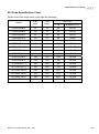
B.3 Fuse Specification Chart ....................................................................B-3
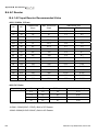
B.4 AC Reactor ........................................................................................B-3
B.4.1 AC Input Reactor Recommended Value..................................... B-3
B.4.2 AC Output Reactor Recommended Value.................................. B-3
B.4.3 Applications ................................................................................ B-3
B.5 Zero Phase Reactor (RF220X00A) ....................................................B-3
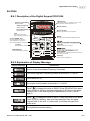
B.6 PU06 ..................................................................................................B-3
B.6.1 Description of the Digital Keypad VFD-PU06 ............................. B-3
B.6.2 Explanation of Display Message .................................................B-3
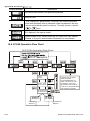
B.6.3 PU06 Operation Flow Chart ........................................................B-3
Appendix C How to Select the Right AC Motor Drive .............................. C-3
C.1 Capacity Formulas ............................................................................ C-3
C.2 General Precaution ........................................................................... C-3
C.3 How to Choose a Suitable Motor....................................................... C-3
Chapter 1 Introduction
1.1 Receiving and Inspection
This VFD-G AC motor drive has gone through rigorous quality control tests at the factory before
shipment. After receiving the AC motor drive, please check for the following:
Check to make sure that the package includes an AC motor drive, the User Manual/Quick Start
and CD, dust covers and rubber bushings.
Inspect the unit to assure it was not damaged during shipment.
Make sure that the part number indicated on the nameplate corresponds with the part number of
your order.
1.1.1 Nameplate Information
Example for 10HP/7.5kW 3-phase 460V AC drive
AC Drive Model
Input Spec.
Output Spec.
Output Frequency Range
Enclosure type
MODE
: VFD075F43A-G
INPUT
: 3PH 380-480V 50/60Hz 19.0A
OUTPUT
: 3PH 0-480V 18A 14kVA 10HP
Freq. Range : 0.1~120.00Hz
ENCLOSURE: TYPE 1
Bar Code
075F43AG4T5010001
Serial Number
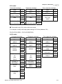
1.1.2 Model Explanation
VFD 075 F
43 A - G
Series
Name
VFD-G series
Version Type
Input Voltage
43:Three phase 460V
Applicable motor capacity
055:7.5HP(5.5kW)
150:20HP(15kW)
300:40HP(30kW)
550:75HP(55kW)
1100:150HP(110kW)
1850:250HP(185kW)
Revision July 2008, EG03, SW V1.06
075:10HP(7.5kW)
185:25HP(18.5kW)
370:50HP(37kW)
750:100HP(75kW)
1320:175HP(132kW)
2200:300HP(220kW)
110:15HP(11kW)
220:30HP(22kW)
450:60HP(45kW)
900:125HP(90kW)
1600:215HP(160kW)
1-1
Chapter 1 Introduction|
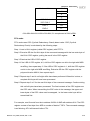
1.1.3 Series Number Explanation
075F43AG4 T 7 01 0001
Production number
460V 3-PHASE 10HP(7.5kW)
Production model
If the nameplate information does not correspond to your purchase order or if there are
any problems, please contact your distributor.
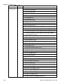
1.1.4 Drive Frames
Frame
Power Range
Models
7.5-20HP (5.5-15kW)
VFD055F43B-G, VFD075F43B-G, VFD110F43A-G,
VFD150F43A-G
D
25-40HP (18.5-30kW)
VFD185F43A-G, VFD220F43A-G, VFD300F43A-G
E
50-75HP (37-55kW)
VFD370F43A-G,VFD450F43A-G,VFD550F43A-G
E1
100-125HP (75-90kW)
VFD750F43A-G,VFD900F43C-G
G
150-215HP (110-160kW) VFD1100F43C-G,VFD1320F43A-G,VFD1600F43A-G
H
250-300HP (185-220kW) VFD1850F43A-G, VFD2200F43A-G
C
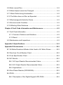
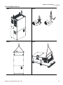
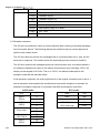
1.2 Appearances
(Refer to chapter 2.3 for exact dimensions)
7.5-20HP/5.5-15kW(Frame C)
1-2
25-40HP/18.5-30kW(Frame D)
Revision July 2008, EG03, SW V1.06
Chapter 1 Introduction|
50-125HP/37-90kW(Frame E, E1)
150-215HP/110-160kW(Frame G)
250-300HP/185-220kW(Frame H)
Revision July 2008, EG03, SW V1.06
1-3
Chapter 1 Introduction|
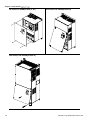
1.3 Remove Instructions
1.3.1 Remove Keypad
1-4
7.5-20HP/5.5-15kW(Frame C)
25-40HP/18.5-30kW(Frame D)
50-125HP/37-90kW(Frame E, E1)
150-215HP/110-160kW(Frame G)
Revision July 2008, EG03, SW V1.06
Chapter 1 Introduction|
250-300HP/185-220kW(Frame H)
1.3.2 Remove Front Cover
7.5-20HP/5.5-15kW(Frame C)
Revision July 2008, EG03, SW V1.06
25-40HP/18.5-30kW(Frame D)
1-5
Chapter 1 Introduction|
50-125HP/37-90kW(Frame E, E1)
150-215HP/110-160kW(Frame G)
250-300HP/185-220kW(Frame H)
1-6
Revision July 2008, EG03, SW V1.06
Chapter 1 Introduction|
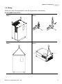
1.4 Lifting
Please carry only fully assembled AC motor drives as shown in the following.
For 50-125HP (Frame E, E1)
Step 1
Step 2
Step 3
Step 4
Revision July 2008, EG03, SW V1.06
1-7
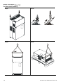
Chapter 1 Introduction|
For 150-215HP (Frame G)
1-8
Step 1
Step 2
Step 3
Step 4
Revision July 2008, EG03, SW V1.06
Chapter 1 Introduction|
For 250-300HP (Frame H)
Step 1
Step 2
Step 3
Step 4
Revision July 2008, EG03, SW V1.06
1-9
Chapter 1 Introduction|
1.5 Preparation for Installation and Wiring
1.5.1 Ambient Conditions
Install the AC motor drive in an environment with the following conditions:
Air Temperature:
-10 ~ +40°C (14 ~ 104°F)
Relative Humidity:
<90%, no condensation allowed
Atmosphere
pressure:
Installation Site
Altitude:
Operation
Storage
Transportation
<1000m
Vibration:
<20Hz: 9.80 m/s2 (1G) max
20 ~ 50Hz: 5.88 m/s2 (0.6G) max
Temperature:
-20°C ~ +60°C (-4°F ~ 140°F)
Relative Humidity:
<90%, no condensation allowed
Atmosphere
pressure:
86 ~ 106 kPa
<20Hz: 9.80 m/s2 (1G) max
20 ~ 50Hz: 5.88 m/s2 (0.6G) max
Vibration:
Pollution Degree
86 ~ 106 kPa
2: good for a factory type environment.
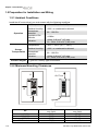
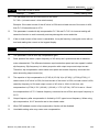
1.5.2 Minimum Mounting Clearances
H
Air Flow
FWD
REV
PROG
DATA
W
W
H
HP
1-5HP
7.5-20HP
25-75HP
100HP and above
1-10
W
mm (inch)
50 (2)
75 (3)
75 (3)
75 (3)
H
mm (inch)
150 (6)
175 (7)
200 (8)
250 (10)
Revision July 2008, EG03, SW V1.06
Chapter 1 Introduction|
CAUTION!
1.
Operating, storing or transporting the AC motor drive outside these conditions may cause
damage to the AC motor drive.
2.
3.
Failure to observe these precautions may void the warranty!
Mount the AC motor drive vertically on a flat vertical surface object by screws. Other directions
are not allowed.
4.
The AC motor drive will generate heat during operation. Allow sufficient space around the unit
for heat dissipation.
5.
The heat sink temperature may rise to 90°C when running. The material on which the AC motor
drive is mounted must be noncombustible and be able to withstand this high temperature.
6.
When AC motor drive is installed in a confined space (e.g. cabinet), the surrounding
temperature must be within 10 ~ 40°C with good ventilation. DO NOT install the AC motor drive
in a space with bad ventilation.
7.
Prevent fiber particles, scraps of paper, saw dust, metal particles, etc. from adhering to the
heatsink.
8.
When installing multiple AC more drives in the same cabinet, they should be adjacent in a row
with enough space in-between. When installing one AC motor drive below another one, use a
metal separation between the AC motor drives to prevent mutual heating.
Revision July 2008, EG03, SW V1.06
1-11
Chapter 1 Introduction|
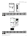
1.6 Dimensions
W
W1
D
H
H1
F
Unit: mm [inch]
Frame
W
W1
H
H1
D
F
C
200.0 [7.88]
185.6 [7.31]
323.0 [12.72]
303.0 [11.93]
183.2 [7.22]
7.0 [0.28]
D
250.0 [9.84]
226.0 [8.90]
403.8 [15.90]
384.0 [15.12]
205.4 [8.08]
10.0 [0.39]
NOTE
Frame C: VFD055F43B-G, VFD075F43B-G, VFD110F43A-G, VFD150F43A-G
Frame D: VFD185F43A-G, VFD220F43A-G, VFD300F43A-G
W
D
W1
H2
H
H1
F
Unit: mm [inch]
Frame
W
W1
H
H1
H2
D
F
E
370.0[14.57]
335.0[13.19]
589.0[23.19]
560.0[22.05]
-
260.0[10.24]
13.0[0.51]
E1
370.0[14.57]
335.0[13.19]
589.0[23.19]
560.0[22.05]
595.0[23.43]
260.0[10.24]
13.0[0.51]
NOTE
Frame E: VFD370F43A-G, VFD450F43A-G, VFD550F43A-G
Frame E1: VFD750F43A-G, VFD900F43C-G
1-12
Revision July 2008, EG03, SW V1.06
Chapter 1 Introduction|
W
W1
D
H2
H1
H
RF
Unit: mm [inch]
Frame
W
W1
H
H1
H2
D
F
G
425.0[16.73]
381.0[15.00]
850.0[33.46]
819.5[32.26]
764.0[30.08]
264.0[10.39]
6.5[0.26]
NOTE
Frame G: VFD1100F43C-G, VFD1320F43A-G, VFD1600F43A-G
Unit: mm [inch]
Frame
W
W1
H
H1
H2
D1
F
H
547.0[21.54]
480.0[18.90]
1150.0[45.28]
1119.0[44.06]
1357.6[53.45]
360.0[14.17]
13.0[0.51]
NOTE
Frame H: VFD1850F43A-G, VFD2200F43A-G
Revision July 2008, EG03, SW V1.06
1-13
Chapter 1 Introduction|
This page intentionally left blank.
1-14
Revision July 2008, EG03, SW V1.06
Chapter 2 Installation and Wiring
After removing the front cover, check if the power and control terminals are clear. Be sure to observe
the following precautions when wiring.
General Wiring Information
Applicable Codes
All VFD-G series are Underwriters Laboratories, Inc. (UL) and Canadian Underwriters
Laboratories (cUL) listed, and therefore comply with the requirements of the National Electrical
Code (NEC) and the Canadian Electrical Code (CEC).
Installation intended to meet the UL and cUL requirements must follow the instructions provided
in “Wiring Notes” as a minimum standard. Follow all local codes that exceed UL and cUL
requirements. Refer to the technical data label affixed to the AC motor drive and the motor
nameplate for electrical data.
The "Line Fuse Specification" in Appendix B, lists the recommended fuse part number for each
VFD-G Series part number. These fuses (or equivalent) must be used on all installations where
compliance with U.L. standards is a required.
CAUTION!
1.
Make sure that power is only applied to the R/L1, S/L2, T/L3 terminals. Failure to comply may
result in damage to the equipment. The voltage and current should lie within the range as
indicated on the nameplate.
2.
All the units must be grounded directly to a common ground terminal to prevent lightning strike
or electric shock.
3.
Please make sure to fasten the screw of the main circuit terminals to prevent sparks which is
made by the loose screws due to vibration.
4.
Check following items after finishing the wiring:
A. Are all connections correct?
B. No loose wires?
C. No short-circuits between terminals or to ground?
Revision July 2008, EG03, SW V1.06
2-1
Chapter 2 Installation and Wiring|
DANGER!
1.
A charge may still remain in the DC bus capacitors with hazardous voltages even if the power
has been turned off. To prevent personal injury, please ensure that the power is turned off and
wait ten minutes for the capacitors to discharge to safe voltage levels before opening the AC
motor drive.
2.
Only qualified personnel familiar with AC motor drives is allowed to perform installation, wiring
and commissioning.
3.
Make sure that the power is off before doing any wiring to prevent electric shock.
2.1 Wiring
Users must connect wires according to the circuit diagrams on the following pages. Do not plug a
modem or telephone line to the RS-485 communication port or permanent damage may result. Pins 1
& 2 are the power supply for the optional copy keypad only and should not be used for RS-485
communication.
2-2
Revision July 2008, EG03, SW V1.06
Chapter 2 Installation and Wiring|
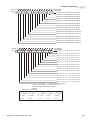
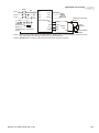
For 460V series, 20hp and below
DC Reactor
(O pti onal)
Br ak e Resistor
(O pti onal)
BR
Jumper
NFB
+1 +2/B1
MC
R/L1
S/L2
T /L3
R/L1
S/L2
B2
VFD-G
T /L3
NFB
U /T1
V/T2
W/T 3
Motor
IM
3~
SA
Recommended C ircui t
when power s upply
is turned O FF by a
fault output
F ac tor y
Setting
RB1
ON
MC
E.F.
F WD/ST OP
REV/STO P
Multi-s tep1
Multi-s tep2
Multi-s tep3
Multi-s tep4
Digital Si gnal Common
*Don't apply the mains voltage
dir ectly to abov e terminals.
0-10V
V
RA1
RC1
O FF
RB1
+24V
EF
F WD
REV
Sink
MI1
MI2 Multi-function
MI3 input
MI4 terminals
DCM
+12V
ACM
AI1
Analog Signal Common
0~10V
AO M
E
6←1
AC1
AI2
0-10V
AF M1
AF M2
Multi-function Analog
output ter minal
Fa ctor y setti ng : ou tpu t fre qu en cy
0 ~1 0V DC/2mA
Fa ctor y setti ng : ou tpu t cur re nt
Analog Signal Common
0-1A
S W2
0~1A
V
F ac tor y setting: dis able
Source
A
0~10V
RC1
Sw1
Mu lti -fu ncti on in di cati on
o utp ut co nta cts
2 40 VA C 2 .5A
1 20 VA C 5 A
2 8V DC 5A
0-1A
S W3
A
RS-485
Seri al communic ation inter fac e
1: Reserv ed
2: G ND
3: SG 4: SG +
5: Reserv ed
6: Reserv ed
0~1A
Analog Signal Common
AC2
Main c irc ui t (power) terminals
Revision July 2008, EG03, SW V1.06
NOT E:*1- 3 are o pt io n al.
Contr ol c ircuit ter minals
2-3
Chapter 2 Installation and Wiring|
Br ak e
Unit (O ptional )
For 460V series, 25hp and above
DC Reactor
(O pti onal)
V FDB
B1
Br ak e
R esistor
(O pti onal)
P N B2
Jumper
NFB
S/L2
T /L3
+1
MC
R/L1
R/L1
S/L2
-
+2
VFD-G
T /L3
NFB
U /T1
V/T2
W/T 3
Motor
IM
3~
SA
Recommended C ircui t
when power s upply
is turned O FF by a
fault output
F ac tor y
Setting
RB1
ON
MC
E.F.
F WD/ST OP
REV/STO P
Multi-s tep1
Multi-s tep2
Multi-s tep3
Multi-s tep4
Digital Si gnal Common
*Don't apply the mains voltage
dir ectly to abov e terminals.
0-10V
V
RA1
RC1
O FF
RB1
+24V
EF
F WD
REV
Sink
MI1
MI2 Multi-function
MI3 input
MI4 terminals
DCM
+12V
ACM
AI1
Analog Signal Common
0~10V
AC1
0-1A
S W3
A
E
Multi-function Analog
output ter minal
Fa ctor y setti ng : ou tpu t fre qu en cy
0 ~1 0V DC/2mA
Fa ctor y setti ng : ou tpu t cur re nt
Analog Signal Common
RS-485
Seri al communic ation inter fac e
1: Reserv ed
2: G ND
3: SG 4: SG +
5: Reserv ed
6: Reserv ed
0~1A
Analog Signal Common
AC2
Main c irc ui t (power) terminals
2-4
AO M
6←1
AI2
0-10V
AF M1
AF M2
0-1A
S W2
0~1A
V
F ac tor y setting: dis able
Source
A
0~10V
RC1
Sw1
Mu lti -fu ncti on in di cati on
o utp ut co nta cts
2 40 VA C 2 .5A
1 20 VA C 5 A
2 8V DC 5A
NOT E:*1- 3 are o pt io n al.
Contr ol c ircuit ter minals
Revision July 2008, EG03, SW V1.06
Chapter 2 Installation and Wiring|
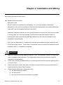
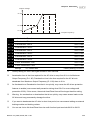
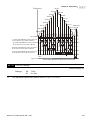
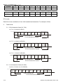
Wiring for SINK mode and SOURCE mode
SINK Mode
E.F.
FWD/STOP
REV/STOP
Multi-step1
Multi-step2
Multi-step3
Multi-step4
Digital Signal Common
*Don't apply the mains voltage directly
to above terminals
SOURCE Mode
Sink
Sw1
Source
+24V
EF
FWD
REV
MI1
MI2
MI3
MI4
DCM
+24V
E.F.
FWD/STOP
REV/STOP
Multi-step1
Multi-step2
Multi-step3
Multi-step4
*Don't apply the mains voltage directly
to above terminals
EF
FWD
REV
MI1
MI2
MI3
MI4
DCM
CAUTION!
1.
2.
The wiring of main circuit and control circuit should be separated to prevent erroneous actions.
Please use shield wire for the control wiring and not to expose the peeled-off net in front of the
terminal.
3.
Please use the shield wire or tube for the power wiring and ground the two ends of the shield
wire or tube.
4.
Damaged insulation of wiring may cause personal injury or damage to circuits/equipment if it
comes in contact with high voltage.
5.
The AC motor drive, motor and wiring may cause interference. To prevent the equipment
damage, please take care of the erroneous actions of the surrounding sensors and the
equipment.
6.
When the AC drive output terminals U/T1, V/T2, and W/T3 are connected to the motor terminals
U/T1, V/T2, and W/T3, respectively. To permanently reverse the direction of motor rotation,
switch over any of the two motor leads.
Revision July 2008, EG03, SW V1.06
2-5
Chapter 2 Installation and Wiring|
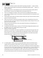
7.
With long motor cables, high capacitive switching current peaks can cause over-current, high
leakage current or lower current readout accuracy. To prevent this, the motor cable should be
less than 20m for 3.7kW models and below. And the cable should be less than 50m for 5.5kW
models and above. For longer motor cables use an AC output reactor.
8.
The AC motor drive, electric welding machine and the greater horsepower motor should be
grounded separately.
9.
10.
Use ground leads that comply with local regulations and keep them as short as possible.
No brake resistor is built in the VFD-G series, it can install brake resistor for those occasions
that use higher load inertia or frequent start/stop. Refer to Appendix B for details.
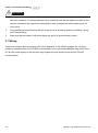
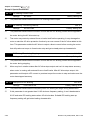
11.
Multiple VFD-G units can be installed in one location. All the units should be grounded directly
to a common ground terminal, as shown in the figure below. Ensure there are no ground
loops.
Excellent
Good
Not allowed
2-6
Revision July 2008, EG03, SW V1.06
Chapter 2 Installation and Wiring|
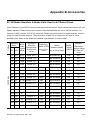
2.2 External Wiring
Items
Power
supply
FUSE/NFB
Fuse/NFB
(Optional)
There may be an inrush current during
power up. Please check the chart of
Appendix B and select the correct fuse
with rated current. Use of an NFB is
optional.
Magnetic
contactor
Magnetic
contactor
(Optional)
Please do not use a Magnetic
contactor as the I/O switch of the AC
motor drive, as it will reduce the
operating life cycle of the AC drive.
Power Supply
Input AC
Line Reactor
Zero-phase
Reactor
EMI Filter
R/L1
S/L2
T/L3
+1
BR
VF DB
Brake
u ni t
V/T2
Brake
resi stor
DC
Choke
+2
U/T1
Explanations
Please follow the specific power
supply requirements shown in
Appendix A.
W/T3
Zer o-phase
Reactor
Output AC
Line Reactor
Motor
Revision July 2008, EG03, SW V1.06
Used to improve the input power
factor, to reduce harmonics and
provide protection from AC line
disturbances (surges, switching
spikes, short interruptions, etc.). AC
Input AC
Line Reactor line reactor should be installed when
the power supply capacity is ≧500kVA
(Optional)
or phase lead reactor will be switched.
And the mains wiring distance ≤ 10m.
Please refer to Appendix B for more
details.
Zero phase reactors are used to
reduce radio noise especially when
Zero-phase
audio equipment is installed near the
Reactor
inverter. Effective for noise reduction
(Ferrite Core
on both the input and output sides.
Common
Attenuation quality is good for a wide
Choke)
range from AM band to 10MHz.
(Optional)
Appendix B specifies the zero phase
reactor. (RF220X00A)
EMI filter
(Optional)
To reduce electromagnetic
interference, please refer to Appendix
B for more details.
Brake
Resistor
(Optional)
Used to reduce the deceleration time
of the motor. Please refer to the chart
in Appendix B for specific Brake
Resistors.
Motor surge voltage amplitude
Output AC
depends on motor cable length. For
Line Reactor applications with long motor cable
(Optional)
(>20m), it is necessary to install a
reactor at the inverter output side.
2-7
Chapter 2 Installation and Wiring|
2.3 Main Circuit Connection
For 460V series, 20hp and below
DC Reactor
(O pti onal)
Br ak e Resistor
(O pti onal)
BR
Jumper
NFB
S/L2
T /L3
+1 +2/B1
MC
R/L1
R/L1
S/L2
W/T 3
Br ak e
Unit (O pti onal)
DC Reactor
(O pti onal)
V FDB
B1
P N B2
Br ak e
Resistor
(O pti onal)
Jumper
NFB
S/L2
T /L3
+1
MC
+2
R/L1
S/L2
T /L3
NFB
Terminal Symbol
IM
3~
V/T2
For 460V series, 25hp and above
R/L1
Motor
U/T1
VFD-G
T /L3
NFB
-
B2
VFD-G
U/T1
V/T2
W/T 3
IM
3~
Explanation of Terminal Function
R/L1, S/L2, T/L3
AC line input terminals
U/T1, V/T2, W/T3
AC drive output terminals motor connections
+1, +2
Connections for DC Link Reactor (optional)
+2/B1~B2
Connections for Braking Resistor (optional)
+2~ -, +2/B1~ -
Motor
Connections for External Braking Unit (VFDB series)
Earth Ground
2-8
Revision July 2008, EG03, SW V1.06
Chapter 2 Installation and Wiring|
CAUTION!
Mains power terminals (R/L1, S/L2, T/L3)
Connect these terminals (R/L1, S/L2, T/L3) via a non-fuse breaker or earth leakage breaker to 3phase AC power (some models to 1-phase AC power) for circuit protection. It is unnecessary to
consider phase-sequence.
It is recommended to add a magnetic contactor (MC) in the power input wiring to cut off power
quickly and reduce malfunction when activating the protection function of AC motor drives. Both
ends of the MC should have an R-C surge absorber.
Please make sure to fasten the screw of the main circuit terminals to prevent sparks which is
made by the loose screws due to vibration.
Please use voltage and current within the regulation shown in Appendix A.
When using a general GFCI (Ground Fault Circuit Interrupter), select a current sensor with
sensitivity of 200mA or above, and not less than 0.1-second detection time to avoid nuisance
tripping. For the specific GFCI of the AC motor drive, please select a current sensor with
sensitivity of 30mA or above.
Do NOT run/stop AC motor drives by turning the power ON/OFF. Run/stop AC motor drives by
RUN/STOP command via control terminals or keypad. If you still need to run/stop AC drives by
turning power ON/OFF, it is recommended to do so only ONCE per hour.
Do NOT connect 3-phase models to a 1-phase power source.
Output terminals for main circuit (U, V, W)
When it needs to install the filter at the output side of terminals U/T1, V/T2, W/T3 on the AC
motor drive. Please use inductance filter. Do not use phase-compensation capacitors or L-C
(Inductance-Capacitance) or R-C (Resistance-Capacitance), unless approved by Delta.
DO NOT connect phase-compensation capacitors or surge absorbers at the output terminals of
AC motor drives.
Use well-insulated motor, suitable for inverter operation.
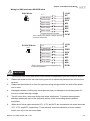
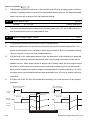
Terminals [+1, +2(+2/B1)] for connecting DC reactor
DC Reactor
Jumper
DC Reactor
Jumper
+1
For 460V series, 20HP and below
Revision July 2008, EG03, SW V1.06
+1
For 460V series, 25HP and above
2-9
Chapter 2 Installation and Wiring|
To improve the power factor and reduce harmonics, connect a DC reactor between terminals [+1,
+2(+2/B1)]. Please remove the jumper before connecting the DC reactor.
Models of 18.5kW~160kW have a built-in DC reactor; models of 185kW~220kW have a built-in
AC reactor.
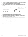
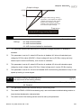
Terminals [+2/B1, B2] for connecting brake resistor and terminals [+2(+2/B1), -] for connecting
external brake unit
BR
Bra ke Resistor (Opt io nal)
Ref er to Appen dix B for details.
Bra ke Resistor/Unit (Opt ional)
Ref er to App endix B f or deta ils.
VFDB
BR
+2/B1
B2
Fo r 460V series, 20H P and below
-
+2
Fo r 460V ser ies, 25HP an d abo ve
Connect a brake resistor or brake unit in applications with frequent deceleration ramps, short
deceleration time, too low brake torque or requiring increased brake torque.
If the AC motor drive has a built-in brake chopper (all models of 15kW and below), connect the
external brake resistor to the terminals [+2/B1, B2].
Models of 18.5kW and above don’t have a built-in brake chopper. Please connect an external
optional brake unit (VFDB-series) and brake resistor. Refer to VFDB series user manual for
details.
When not used, please leave the terminals [+2(+2/B1), -] open.
Short-circuiting [B2] or [-] to [+2/B1] can damage the AC motor drive.
Connect the terminals [+(P), -(N)] of the brake unit to the AC motor drive terminals
[+2(+2/B1), -]. The length of wiring should be less than 5m with twisted cable.
2-10
Revision July 2008, EG03, SW V1.06
Chapter 2 Installation and Wiring|
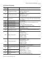
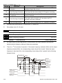
2.4 Control Terminals
Terminal
Symbol
Terminal Function
Factory Settings
FWD
Forward-Stop command
FWD-DCM:
ON: Run in FWD direction
OFF: Ramp to stop
REV
Reverse-Stop command
REV-DCM:
ON: Run in REV direction
OFF: Ramp to stop
EF
External fault
EF-DCM:
ON: External Fault. Display “EF” and coast/ramp to stop
OFF: No fault
MI1
Multi-function Input 1
MI2
Multi-function Input 2
MI3
Multi-function Input 3
MI4
Multi-function Input 4
MI1~MI4-DCM:
Refer to Pr.04-00~Pr.04-03 for programming multifunction inputs.
ON: the activation current is 16mA.
OFF: leakage current tolerance is 10μA.
+24V
DC Voltage Source
+24V 20mA
used for Source mode.
DCM
Digital Signal Common
Used as common for digital inputs and used for Sink
mode.
Analog output meter 1
0 to 10V, 2mA
Impedance: 470Ω
Output current: 2mA max
Resolution: 8 bits
Range: 0 ~ 10VDC
Function: Pr.03-05
AFM1
Load Impedance: ≦500Ω
Output current: 20mA max
Resolution: 8 bits
Range: 0/4 ~ 20mA
Function: Pr.03-06
AFM2
Analog output meter 2
AOM
Analog control signal common Used as common for analog outputs.
RA1
Multi-function Relay1 output
(N.O.) a
RB1
Multi-function Relay1 output
(N.C.) b
RC1
Multi-function Relay1
common
Revision July 2008, EG03, SW V1.06
Resistive Load:
5A(N.O.)/3A(N.C.) 240VAC
5A(N.O.)/3A(N.C.) 24VDC
Inductive Load:
1.5A(N.O.)/0.5A(N.C.) 240VAC
1.5A(N.O.)/0.5A(N.C.) 24VDC
Refer to Pr.03-00 for programming.
2-11
Chapter 2 Installation and Wiring|
Terminal
Symbol
Terminal Function
Factory Settings
+12V/ACM Potentiometer power source
+12Vdc 20mA (Variable Resistor: 3~5KΩ)
AI1
Analog voltage/current Input
0~10V/0~1A correspond to 0~Max. operation frequency
Resolution: 10 bits
Function: Pr.04-05 ~ Pr.04-25
AI2
Analog voltage/current Input
0~10V/0~1A correspond to 0~Max. operation frequency
Resolution: 10 bits
Funciton: Pr.04-05 ~ Pr.04-25
AC1/AC2 Analog control signal common Used as common for analog inputs.
NOTE: Control signal wiring size: 18 AWG (0.75 mm2) with shielded wire.
Analog inputs (AI1, AI2, AC1, AC2)
Analog input signals are easily affected by external noise. Use shielded wiring and keep it as
short as possible (<20m) with proper grounding. If the noise is inductive, connecting the shield to
terminal AC1/AC2 can bring improvement.
If the analog input signals are affected by noise from the AC motor drive, please connect a
capacitor (0.1 μ F and above) and ferrite core as indicated in the following diagrams:
AI1/AI2
C
AC1/AC2
ferrite core
wind each wires 3 times or more around the core
Digital inputs (MI1~MI4, DCM, FWD, REV, EF)
When using contacts or switches to control the digital inputs, please use high quality
components to avoid contact bounce.
Relay outputs (RA1, RB1, RC1)
Make sure to connect the digital outputs to the right polarity, see wiring diagrams.
When connecting a relay to the digital outputs, connect a surge absorber or fly-back diode
across the coil and check the polarity.
2-12
Revision July 2008, EG03, SW V1.06
Chapter 2 Installation and Wiring|
General
Keep control wiring as far away as possible from the power wiring and in separate conduits to
avoid interference. If necessary let them cross only at 90º angle.
The AC motor drive control wiring should be properly installed and not touch any live power
wiring or terminals.
NOTE
If a filter is required for reducing EMI (Electro Magnetic Interference), install it as close as
possible to AC drive. EMI can also be reduced by lowering the Carrier Frequency.
DANGER!
Damaged insulation of wiring may cause personal injury or damage to circuits/equipment if it comes
in contact with high voltage.
Revision July 2008, EG03, SW V1.06
2-13
Chapter 2 Installation and Wiring|
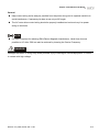
2.5 Specification for main circuit terminals and control terminals
7.5 HP to 20 HP (VFD055F43B-G, VFD075F43B-G, VFD110F43A-G, VFD150F43A-G)
POWER
IM
3
MOTOR
Control Terminal
Torque: 4Kgf-cm (3 in-lbf)
Wire: 12-24 AWG
Power Terminal
Torque: 30Kgf-cm (26 in-lbf)
Wire: 12-8 AWG
Wire Type: Stranded copper only, 75° C
NOTE: If wiring of the terminal utilizes the wire with a 6AWG-diameter, it is thus necessary to
use the Recognized Ring Terminal to conduct a proper wiring.
2-14
Revision July 2008, EG03, SW V1.06
Chapter 2 Installation and Wiring|
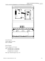
25 HP to 40 HP (VFD185F43A-G, VFD220F43A-G, VFD300F43A-G)
R/L1 S/L2 T/L3 +1
POWER
+2
DC (+)
-
DC ( - )
V/T2 W/T3
IM
3
MOTOR
Control Terminal
Torque: 4Kgf-cm (3 in-lbf)
Wire: 12-24 AWG
Power Terminal
Torque: 30Kgf-cm (26 in-lbf)
Wire: 8-2 AWG
Wire Type: Stranded copper only, 75° C
NOTE: If wiring of the terminal utilizes the wire with a 1AWG-diameter, it is thus necessary to
use the Recognized Ring Terminal to conduct a proper wiring.
Revision July 2008, EG03, SW V1.06
2-15
Chapter 2 Installation and Wiring|
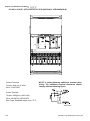
50 HP to 60 HP (VFD370F43A-G, VFD450F43A-G)
POWER
ALARM
CHARGE
R/L1 S/L2 T/L3
POWER
+1
+2
-
U/T1 V/T2 2/T3
IM
3
MOTOR
Control Terminal
Torque: 4Kgf-cm (3 in-lbf)
Wire: 12-24 AWG
Power Terminal
Torque: 57kgf-cm (49.5 in-lbf) min.
Wire: VFD370F43A-G: 3AWG
VFD450F43A-G: 2AWG
Wire Type: Stranded copper only, 75° C
2-16
Revision July 2008, EG03, SW V1.06
Chapter 2 Installation and Wiring|
75 HP to 125 HP (VFD550F43A-G, VFD750F43A-G, VFD900F43C-G)
POWER
ALARM
CHARGE
R/L1 S/L2 T/L3
POWER
+1
+2
Screw Torque:
200kgf-cm (173in-lbf)
U/T1 V/T2 W/T3
IM
3
MOTOR
Control Terminal
Torque: 4Kgf-cm (3 in-lbf)
Wire: 12-24 AWG
Power Terminal
Torque: 200kgf-cm (173 in-lbf)
Wire: VFD550F43A-G: 1/0-4/0 AWG
VFD750F43A-G: 3/0-4/0 AWG
VFD900F43C-G: 4/0 AWG
Wire Type: Stranded copper only, 75°C
Revision July 2008, EG03, SW V1.06
2-17
Chapter 2 Installation and Wiring|
150 HP to 215 HP (VFD1100F43C-G, VFD1320F43A-G, VFD1600F43A-G)
R/L1 S/L2 T/L3
POWER
Control Terminal
Torque: 4Kgf-cm (3 in-lbf)
Wire: 12-24 AWG
+1 +2
U/T1 V/T2 W/T3
IM
DC(+) DC(-)
MOTOR
3
NOTE: It needs following additional terminal when
wiring. The additional terminal dimension should
comply with the following figure.
Power Terminal
Torque: 300kgf-cm (260 in-lbf)
Wire: 1/0 AWG*2-300 MCM*2
Wire Type: Stranded copper only, 75°C
UNIT:mm
2-18
Revision July 2008, EG03, SW V1.06
Chapter 2 Installation and Wiring|
250 HP to 300 HP (VFD1850F43A-G, VFD2200F43A-G)
R/L1 S/L2 T/L3
POWER
Control Terminal
Torque: 4Kgf-cm (3 in-lbf)
Wire: 12-24 AWG
+
-
DC (+) DC (-)
U/T1 V/T2 W/T3
NOTE: It needs following additional terminal when
wiring, and add insulation sheath on position
where following figure shows.
Power Terminal
Torque: 408kgf-cm (354 in-lbf)
Wire: 500 MCM (max)
Wire Type: Stranded copper only, 75°C
Revision July 2008, EG03, SW V1.06
2-19
Chapter 2 Installation and Wiring|
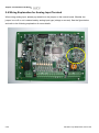
2.6 Wiring Explanation for Analog Input Terminal
When using analog input, please pay attention to the jumper on the control board. Whether the
jumper is cut off or not is determined by analog input type (voltage or current). See the figure below
and refer to the following explanation for more details.
2-20
Revision July 2008, EG03, SW V1.06
Chapter 2 Installation and Wiring|
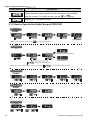
1.
When using analog current input (0~1A), please plug into the left two pins (See the red mark),
and make sure the jumper is connected well (See what the following yellow arrows point at).
2.
When using analog voltage input (0~10V), please transfer to the right two pins (See the red
mark), and cut off the jumper (See what the following yellow arrows point at).
Revision July 2008, EG03, SW V1.06
2-21
Chapter 2 Installation and Wiring|
This page intentionally left blank.
2-22
Revision July 2008, EG03, SW V1.06
Chapter 3 Keypad and Start Up
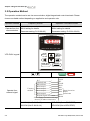
3.1 Digital Keypad VFD-PU01
3.1.1 Description of the Digital Keypad
F
H
U
LED Display
Display frequency, current, voltage
and error, etc.
VFD-PU01
Part Number
Status Display
Display the driver's current status
JOG
By pressing JOG key.
Initiates jog operation.
MODE
Changes between different
JOG
display mode.
Left key
moves cursor to the left
UP and DOWN Key
Sets the parameter
number and changes the
numerical data, such as
Master Frequency.
STOP/RESET
RUN
Display Message
STOP
RESET
RUN key
Descriptions
Display the AC drive Master Frequency.
Display the actual operation frequency present at terminals U/T1, V/T2,
and W/T3.
Display voltage (V), Current (A), power factor and feedback signal (P)
Display the output current present at terminals U/T1, V/T2, and W/T3.
Display the AC drive forward run status.
The AC drive reverse run status.
Display the specified parameter setting.
Display the actual value stored within the specified parameter.
External Fault.
Revision July 2008, EG03, SW V1.06
3-1
Chapter 3 Keypad and Start Up|
Display Message
Descriptions
Display “End” for approximately 1 second if input has been accepted.
After a parameter value has been set, the new value is automatically
stored in memory. To modify an entry, use the
or
keys.
Display “Err”, if the input is invalid.
3.1.2 How to Operate the Digital Keypad VFD-PU01
Selecting mode
START
F
F
F
H
U
F
H
H
H
U
U
U
MODE
MODE
F
H
U
MODE
MODE
MODE
GO START
Note:In the selection mode, press
to set the parameters.
Setting parameters
F
H
U
F
H
U
F
H
U
Success to set parameter.
F
H
U
F
H
U
Input data error
MODE
move to previous display
NOTE:In the parameter setting mode, you can press
MODE
to return the selecting mode.
To shift data
START
F
F
F
F
F
F
H
U
F
H
U
H
U
H
U
H
U
F
H
U
F
H
U
To modify data
F
START
H
U
H
U
H
U
Setting direction
F
H
U
or
3-2
or
Revision July 2008, EG03, SW V1.06
Chapter 3 Keypad and Start Up|
3.1.3 VFD-PU01 Dimensions
110.0 [4.33]
PROG
DATA
8]
.5
77.0 [3.03]
[1
.0
40
MODE
M4* 0.7(2X)
?
JOG
44.0 [1.73]
97.0 [3.82]
19.0 [0.75]
73.0 [2.87]
STOP
6.5 [0.26]
RUN
Unit: mm [inch]
3.1.4 Reference Table for the LED Display of the Digital Keypad
Digit
0
1
2
3
4
5
6
7
8
9
A
b
Cc
d
E
F
G
Hh
Ii
Jj
K
L
n
Oo
P
q
r
S
Tt
U
v
Y
Z
LED
Display
English
alphabet
LED
Display
English
alphabet
LED
Display
English
alphabet
LED
Display
Revision July 2008, EG03, SW V1.06
3-3
Chapter 3 Keypad and Start Up|
3.2 Operation Method
The operation method can be set via communication, digital keypad and control terminals. Please
choose a suitable method depending on application and operation rule.
Operation Method
Frequency Source
Operation Command Source
Refer to the communication address
Operate from the 2001H setting for details.
communication
(Parameter setting: Pr.02-00=03)
Refer to the communication address
2000H setting for details.
(Parameter setting: Pr.02-01=03/04)
F
H
U
VFD-PU01
RUN STOP JOG FWD REV
JOG
VFD-PU01 keypad
RUN
STOP
RESET
RUN
Operate from
external signal
F ac tor y
default
E.F.
F WD/ST OP
REV/STO P
Multi-s tep1
Multi-s tep2
Multi-s tep3
Multi-s tep4
Digital Si gnal Common
*Don't apply the mains voltage
dir ectly to abov e terminals.
3-4
STOP
RESET
+24V
EF
F WD
REV
MI1
MI2 Multi-function
MI3 input
MI4 terminals
DC M
MI1-DCM (Set Pr.04-00=13)
FWD-DCM (Set to FWD/STOP)
MI2-DCM (Set Pr.04-01=14)
REV-DCM (Set to REV/STOP)
Revision July 2008, EG03, SW V1.06
Chapter 3 Keypad and Start Up|
3.3 Trial Run
you can perform a trial run by using digital keypad with the following steps. The factory setting of the
operation source is from the keypad (Pr.02-01=00).
1.
After applying power, verify that LED “F” is on and the display shows 60.00Hz.
2.
Setting frequency to about 5Hz by using
3.
Pressing RUN
key for forward running. And if you want to change to reverse running,
you should press
please press
4.
key.
STOP
RESET
key in
F
H
U
page. And if you want to decelerate to stop,
key.
Check following items:
Check if the motor direction of rotation is correct.
Check if the motor runs steadily without abnormal noise and vibration.
Check if acceleration and deceleration are smooth.
If the results of trial run are normal, please start the formal run.
NOTE
1.
Stop running immediately if any fault occurs and refer to the troubleshooting guide for solving
the problem.
2.
Do NOT touch output terminals U, V, W when power is still applied to L1/R, L2/S, L3/T even
when the AC motor drive has stopped. The DC-link capacitors may still be charged to
hazardous voltage levels, even if the power has been turned off.
3.
To avoid damage to components, do not touch them or the circuit boards with metal objects or
your bare hands.
Revision July 2008, EG03, SW V1.06
3-5
Chapter 3 Keypad and Start Up|
This page intentionally left blank.
3-6
Revision July 2008, EG03, SW V1.06
Chapter 4 Parameters
The VFD-G parameters are divided into 10 groups by property for easy setting. In most applications,
the user can finish all parameter settings before start-up without the need for re-adjustment during
operation.
The 10 groups are as follows:
Group 0: User Parameters
Group 1: Basic Parameters
Group 2: Operation Method Parameters
Group 3: Output Function Parameters
Group 4: Input Function Parameters
Group 5: Multi-Step Speed Parameters
Group 6: Protection Function Parameters
Group 7: AC Drive and Motor Parameters
Group 8: Special Parameters
Group 9: Communication Parameters
Group 10: PID Control Parameters
Revision July 2008, EG03, SW V1.06
4-1
Chapter 4 Parameters|
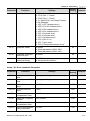
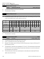
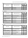
4.1 Summary of Parameter Settings
: The parameter can be set during operation.
Group 0 User Parameters
Parameter
4-2
Functions
Factory
Customer
Setting
Settings
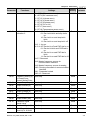
00-00
Software Version
Read only
00-01
AC Drive Status
Indication 1
00: No Fault occurred
01: oc (over current)
02: ov(over voltage)
03: oH(over temperature)
04: oL(overload)
05: oL1(electronic thermal relay)
06: EF(external Fault)
07: occ(AC drive IGBT fault)
08: CF3(CPU failure)
09: HPF(Hardware Protection Failure)
10: ocA(current exceed during Acceleration)
11: ocd(current exceed during Deceleration)
12: ocn(current exceed during Steady State)
13: GFF(Ground Fault)
14: Lv(Low voltage)
15: CF1(abnormal input data)
16: CF2(abnormal output data)
17: bb(Base Block)
18: oL2(over load2)
19: Reserved
20: codE(software or password protection)
21: EF1(external Emergency Stop)
22: PHL(phase loss)
23: Lc (Low Current)
24: FbL(Feedback Loss)
25: Reserved
26: FANP (Fan Power Fault)
27: FF1 (Fan 1 Fault)
28: FF2 (Fan 2 Fault)
29: FF3 (Fan 3 Fault)
30: FF123 (Fan 1, 2, 3 Fault)
31: FF12 (Fan 1, 2 Fault)
32: FF13 (Fan 1, 3 Fault)
33: FF23 (Fan 2, 3 Fault)
34: Fv (Gate Drive Low Voltage Protect)
35~40: Reserved
41: HPF1 (GFF hardware error)
42: HPF2 (CC,OC hardware error)
Read
Revision July 2008, EG03, SW V1.06
Chapter 4 Parameters|
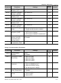
Parameter
Functions
Settings
Factory
Customer
Setting
43: HPF3 (OC hardware error)
44: HPF4 (OV hardware error)
45: CF3.3 (U-phase error)
46: CF3.4 (V-phase error)
47: CF3.5 (W-phase error)
48: CF3.6 (OV or LV)
49: CF3.7 (Isum error)
50: CF3.8 (Temperature sensor error)
AC Drive Status
Indication 2
00-03
Frequency Setting (F) Read only
or Closed Loop
Control Setting Point
Read
00-04
Output Frequency (H) Read only
Read
00-05
Output Current (A)
Read
00-06
DC-BUS Voltage (U)
Read only
Read
00-07
Output Voltage (E)
Read only
Read
00-08
Output Power Factor
(n)
Read only
Read
00-09
Output Power (kW)
Read only
Read
00-10
Feedback Signal
Actual Value
Read only
Read
00-11
Feedback Signal (%)
Read only
Read
00-12
User Target Value
(Low bit) uL 0-99.99
Read only
Read
Revision July 2008, EG03, SW V1.06
Bit 0~1: 00: Run led is off and stop led is on.
01: Run led is blink and stop led is
on.
10: Run led is on and stop led is
blink.
11: Run led is on and stop led is off.
Bit 2: 1: Jog on.
Bit 3~4: 00: Rev led is off and FWD led is on.
01: Rev led is blink and FWD led is
on.
10: Rev led is on and FWD led is
blink.
11: Rev led is on and FWD led is off.
Bit 5-7: Reserved
Bit 8: Master frequency source via
communication interface
Bit 9: Master frequency source via analog
Bit10: Running command via communication
interface
Bit11: Parameter locked
Bit12~15: Reserved
Read
00-02
Read only
4-3
Chapter 4 Parameters|
Parameter
Functions
Settings
Factory
Customer
Setting
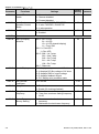
00-13
User Target Value
(High bit) uH 0-9999
Read only
Read
00-14
PLC Time
Read only
Read
00-15
Output Reactive
Power (KVAR)
Read only
Read
Group 1 Basic Parameters
Parameter
4-4
Functions
Settings
Factory
Customer
Setting
01-00
Maximum Output
Frequency
50.00~160.00Hz
60.00
01-01
Maximum Voltage
Frequency
(Base Frequency)
0.10~160.00 Hz
60.00
01-02
Maximum Output
Voltage
0.2V ~ 510.0V
440.0
01-03
Mid-point Frequency
0.10~120 Hz
3.00
01-04
Mid-point Voltage
0.2V~510.0V
11.0
01-05
Minimum Output
Frequency
0.10~20.00 Hz
3.00
01-06
Minimum Output
Voltage
0.2V~100.0V
11.0
01-07
Upper Bound
Frequency
0.00~160.00 Hz
60.00
01-08
Lower Bound
Frequency
0.00~160.00 Hz
0.00
01-09
Acceleration Time 1
0.1~3600.0 Sec
10.0/
60.0
01-10
Deceleration Time 1
0.1~3600.0 Sec
10.0/
60.0
01-11
Acceleration Time 2
0.1~3600.0 Sec
10.0/
60.0
01-12
Deceleration Time 2
0.1~3600.0 Sec
10.0/
60.0
01-13
Acceleration Time 3
0.1~3600.0 Sec
10.0/
60.0
01-14
Deceleration Time 3
0.1~3600.0 Sec
10.0/
60.0
01-15
Acceleration Time 4
0.1~3600.0 Sec
10.0/
60.0
01-16
Deceleration Time 4
0.1~3600.0 Sec
10.0/
60.0
Revision July 2008, EG03, SW V1.06
Chapter 4 Parameters|
Parameter
Functions
Settings
Factory
Customer
Setting
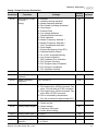
01-17
JOG Acceleration
Time
0.1~3600.0 Sec
10.0/
60.0
01-18
JOG Deceleration
Time
0.1~3600.0 Sec
10.0/
60.0
JOG Frequency
0.0 Hz~160.00 Hz
6.00
01-20
01-19
S Curve Delay Time
in Accel
0.00~2.50sec
0.00
01-21
S Curve Delay Time
in Decel
0.00~2.50sec
0.00
Modulation Index
0.90~1.20
1.00
01-22
01-23
Accel/Decel Time Unit 00: Unit is 1 Sec
01: Unit is 0.1 Sec
02: Unit is 0.01 Sec
01
Group 2 Operation Method Parameters
Parameter
Functions
Settings
Factory
Customer
Setting
02-00
Source of Frequency
Command
00: via keypad
01: via analog input AI1
02: via analog input AI2
03: via RS485 serial communication
04: via External Reference
00
02-01
Source of Operation
Command
00: Controlled by the digital keypad
01: Controlled by the external terminals,
keypad STOP enabled.
02: Controlled by external terminals, keypad
STOP disabled.
03: Controlled by the RS-485 communication
interface, keypad STOP enabled.
04: Controlled by the RS-485 communication
interface, keypad STOP disabled.
00
Stop Method
00: Stop = ramp to stop, E.F. (External Fault)
= coast to stop
01: Stop = coast to stop, E.F. = coast to stop
02: Stop = ramp to stop, E.F. = ramp to stop
03: Stop = coast to stop, E.F. = ramp to stop
00
02-02
02-03
PWM Carrier
7.5~10HP: 4000~6000Hz
Frequency Selections 15~30HP: 3000~6000Hz
40~125HP: 2000~6000Hz
150~300HP: 2000~4000Hz
Revision July 2008, EG03, SW V1.06
6000
6000
4000
4000
4-5
Chapter 4 Parameters|
Parameter
4-6
Functions
Factory
Customer
Setting
Settings
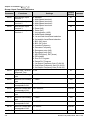
02-04
Forward/Reverse
Enable
00: Forward enabled
01: Reverse disabled
02: Forward disabled
00
02-05
2-wire/3-wire
Operation Control
Modes
00: 2-wire: FWD/STOP, REV/STOP
01: 2-wire: FWD/REV, RUN/STOP
02: 3-wire operation
00
02-06
Line Start Lockout
00: Disabled
01: Enabled
01
02-07
Reserved
02-08
Start-up Display
Selection
Bit0~1: 00 = F LED
01 = H LED
10 = U LED (special display)
11 = Fwd / Rev
Bit2: 0 = Fwd LED /
1 = Rev LED
Bit3~5: 000 = 1st 7-step
001 = 2nd 7-step
010 = 3rd 7-step
011 = 4th 7-step
100 = 5th 7-step
Bit6~7: Reserved
00
02-09
Special Display
00: A displays output current of AC drive
01: U displays DC-Bus voltage of AC drive
02: E displays RMS of output voltage
03: P displays feedback Signal
04: PLC display auto procedure state
00
02-10
User Defined
Coefficient
0.01~160.00
02-11
Flying Start
00: Disabled
01: Enable (Dc braking disabled)
00
02-12
Flying Start
Frequency
00: Trace from master frequency command
01: Trace from maximum setting frequency
01-00
00
02-13
Master Frequency
Memory Setting
00: Do not remember the last known
frequency
01: Remember the last known frequency
01
1.00
Revision July 2008, EG03, SW V1.06
Chapter 4 Parameters|
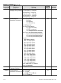
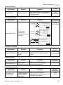
Group 3 Output Function Parameters
Parameter
Functions
Settings
01
03-00
Multi-function Output
Terminal 1
(Relay)
03-01
Reserved
03-02
Master Frequency
Attained 1
0.00~160.00 Hz
0.00
03-03
Master Frequency
Attained 2
0.00~160.00 Hz
0.00
03-04
DC Fan Control
00: Fan runs on power up.
01: Fan begins upon a RUN command. Fan
stops 1 minute after a STOP command.
02: Fan begins upon a RUN command. Fan
stops after a STOP command
03: Fan is controlled by temperature.
Fan will be started at approximate 60°C.
03-05
Analog Output Signal 00: Output frequency
1
01: Output current
Analog Output Signal 02: Output voltage
2
03: Frequency command
04: Power factor loading
00
Analog Output Gain 1 01~200%
100
Analog Output Gain 2 01~200%
Analog Output 2
00: 0~20mA
Selection
01: 4~20mA
100
01
03-06
03-07
03-08
03-09
Revision July 2008, EG03, SW V1.06
00: disabled
01: Indication during operation
02: Master frequency attained
03: Zero Speed (including shutdown)
04: Over-torque
05: External Fault
06: Low voltage detection
07: Operation Mode indication
08: Fault indication
09: Master Frequency Attained 1
10: Master Frequency Attained 2
11: Over Temperature indication
12: Drive Ready
13: External Emergency Stop (EF1)
14: Software Braking Output
15: OL or OL1 Overload Warning
16: Low Current Indication
17: PID Feedback Error Indication
18: PLC Program Running
19: PLC Program Step Completed
20: PLC Program Completed
21: PLC Operation Paused
Factory
Customer
Setting
00
01
4-7
Chapter 4 Parameters|
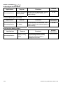
Group 4 Input Function Parameters
Parameter
Factory
Customer
Setting
Settings
00: disabled
01: Multi-Speed terminal 1
02: Multi-Speed terminal 2
03: Multi-Speed terminal 3
04: Multi-Speed terminal 4
05: Reset (NO)
06: Reset (NC)
07: Jog operation (JOG)
08: Accel/Decel disabled
09: 1st and 2nd Accel/Decel selection
10: 3rd and 4th Accel/Decel selection
11: B.B. (NO) input
12: B.B. (NC) input
13: Increase Frequency
14: Decrease Frequency
15: Emergency stop (NO)
16: Emergency stop (NC)
17: KEYPAD(open), EXT(close)
18: PID disable
19: Run PLC Program
20: Pause PLC Program
21: 1st Output Frequency Gain (Pr.04-30)
22: 2nd Output Frequency Gain (Pr.04-31)
23: 3rd Output Frequency Gain (Pr.04-32)
04-00
Multi-function Input
Terminal 1
04-01
Multi-function Input
Terminal 2
04-02
Multi-function Input
Terminal 3
04-03
Multi-function Input
Terminal 4
04-04
Digital Input Terminal 01~20
Response Time
01
04-05
Minimum AI1 Analog
Input
0
04-06
Maximum AI1 Analog 0 ~ 100%
Input
100
04-07
Minimum Output that
corresponds to AI1
0.00
04-08
Maximum Output that 0.00~100.00%
corresponds to AI1
04-09
Minimum AI2 Analog
Input
04-10
Maximum AI2 Analog 0 ~ 100%
Input
100
04-11
Minimum Output that
corresponds to AI2
0.00
04-12
Maximum Output that 0.0~100.0%
corresponds to AI2
100.00
1st AI1 Gain
100.0
04-13
4-8
Functions
0 ~ 100%
0.00~100.00%
0 ~ 100%
0.0~100.0%
0.0~100.0%
01
02
03
04
100.00
0
Revision July 2008, EG03, SW V1.06
Chapter 4 Parameters|
Parameter
Functions
Settings
Factory
Customer
Setting
04-14
2nd AI1 Gain
0.0~100.0%
100.0
04-15
3rd AI1 Gain
0.0~100.0%
100.0
04-16
4th AI1 Gain
0.0~100.0%
100.0
04-17
5th AI1 Gain
0.0~100.0%
100.0
04-18
1st AI2 Gain
0.0~100.0%
100.0
04-19
2nd AI2 Gain
0.0~100.0%
100.0
04-20
3rd AI2 Gain
0.0~100.0%
100.0
04-21
4th AI2 Gain
0.0~100.0%
100.0
04-22
5th AI2 Gain
0.0~100.0%
100.0
04-23
Analog Input Delay
AI1
0.00~10.00 Sec
0.50
04-24
Analog Input Delay
AI2
0.00~10.00 Sec
0.50
04-25
Summation of
External Frequency
Sources
00: Disabled
01:AI1*( AI1 Gain) + AI2*( AI2 Gain)
02:AI1*( AI1 Gain) - AI2*( AI2 Gain)
03: AI1*( AI1 Gain) * AI2 *( AI2 Gain)
04: Reserved
05: Communication master
frequency+AI1*( AI1 Gain)
06: Communication master
frequency+AI2*( AI2 Gain)
07: Max (AI1*( AI1 Gain), AI2*( AI2 Gain))
04-26
1st AI Frequency
Gain
0.00: Disabled
0.01~160.00 Hz
0.00
04-27
2nd AI Frequency
Gain
0.00: Disabled
0.01~160.00 Hz
0.00
04-28
3rd AI Frequency
Gain
0.00: Disabled
0.01~160.00 Hz
0.00
04-29
4th AI Frequency
Gain
0.00: Disabled
0.01~160.00 Hz
0.00
04-30
1st Out Frequency
Gain
0.0 to 200.0%
100.0
04-31
2nd Out Frequency
Gain
0.0 to 200.0%
100.0
04-32
3rd Out Frequency
Gain
0.0 to 200.0%
100.0
Revision July 2008, EG03, SW V1.06
00
4-9
Chapter 4 Parameters|
Group 5 Multi-step Speed Parameters
Parameter
Functions
Factory
Customer
Setting
Settings
05-00
1st Step Speed
Frequency
0.00~160.00 Hz
0.00
05-01
2nd Step Speed
Frequency
0.00~160.00 Hz
0.00
05-02
3rd Step Speed
Frequency
0.00~160.00 Hz
0.00
05-03
4th Step Speed
Frequency
0.00~160.00 Hz
0.00
05-04
5th Step Speed
Frequency
0.00~160.00 Hz
0.00
05-05
6th Step Speed
Frequency
0.00~160.00 Hz
0.00
05-06
7th Step Speed
Frequency
0.00~160.00 Hz
0.00
05-07
8th Step Speed
Frequency
0.00~160.00 Hz
0.00
05-08
9th Step Speed
Frequency
0.00~160.00 Hz
0.00
05-09
10th Step Speed
Frequency
0.00~160.00 Hz
0.00
05-10
11th Step Speed
Frequency
0.00~160.00 Hz
0.00
05-11
12th Step Speed
Frequency
0.00~160.00 Hz
0.00
05-12
13th Step Speed
Frequency
0.00~160.00 Hz
0.00
05-13
14th Step Speed
Frequency
0.00~160.00 Hz
0.00
05-14
15th Step Speed
Frequency
0.00~160.00 Hz
0.00
05-15
PLC Mode
00: Disable PLC Operation
01: Execute one program cycle
02: Continuously execute program cycles
03: Execute one program cycle step by step
04: Continuously execute program cycles
step by step
05-16
PLC Forward/ Reverse
00 to 32767 (00: FWD 01: REV)
Motion
00
05-17
Time Duration Step 1
0.0 to 65500 Sec / 0.0~6550.0 Sec
0.0
05-18
Time Duration Step 2
0.0 to 65500 Sec / 0.0~6550.0 Sec
0.0
05-19
Time Duration Step 3
0.0 to 65500 Sec / 0.0~6550.0 Sec
0.0
4-10
00
Revision July 2008, EG03, SW V1.06
Chapter 4 Parameters|
Parameter
Functions
Settings
Factory
Customer
Setting
05-20
Time Duration Step 4
0.0 to 65500 Sec / 0.0~6550.0 Sec
0.0
05-21
Time Duration Step 5
0.0 to 65500 Sec / 0.0~6550.0 Sec
0.0
05-22
Time Duration Step 6
0.0 to 65500 Sec / 0.0~6550.0 Sec
0.0
05-23
Time Duration Step 7
0.0 to 65500 Sec / 0.0~6550.0 Sec
0.0
05-24
Time Duration Step 8
0.0 to 65500 Sec / 0.0~6550.0 Sec
0.0
05-25
Time Duration Step 9
0.0 to 65500 Sec / 0.0~6550.0 Sec
0.0
05-26
Time Duration Step 10 0.0 to 65500 Sec / 0.0~6550.0 Sec
0.0
05-27
Time Duration Step 11 0.0 to 65500 Sec / 0.0~6550.0 Sec
0.0
05-28
Time Duration Step 12 0.0 to 65500 Sec / 0.0~6550.0 Sec
0.0
05-29
Time Duration Step 13 0.0 to 65500 Sec / 0.0~6550.0 Sec
0.0
05-30
Time Duration Step 14 0.0 to 65500 Sec / 0.0~6550.0 Sec
0.0
05-31
Time Duration Step 15 0.0 to 65500 Sec / 0.0~6550.0 Sec
0.0
05-32
Time Unit Settings
00
00: 1 Sec
01: 0.1 Sec
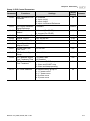
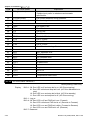
Group 6 Protection Function Parameters
Parameter
Functions
Settings
Factory
Customer
Setting
06-00
Over-voltage Stall
Prevention
660.0V~820.0VDC
00: Disabled
780.0
06-01
Over-current Stall
Prevention during
Acceleration
20~250%
00: Disabled
150%
06-02
Over-current Stall
Prevention during
operation
20~250%
00: Disabled
150%
06-03
Over-torque Detection 00: Over-torque detection disabled.
Selection
01: Over-torque detection enabled during
constant speed operation (OL2), and
operation continues.
02: Over-torque detection enabled during
constant speed operation (OL2), and
operation halted.
03: Over-torque detection enabled during
operation (OL2), and operation
continues.
04: Over-torque detection enabled during
operation (OL2), and operation halted.
00
06-04
Over-torque Detection 30~150%
Level
110
06-05
Over-torque Detection 0.1~60.0 Sec
Time
0.1
Revision July 2008, EG03, SW V1.06
4-11
Chapter 4 Parameters|
Parameter
Functions
Factory
Customer
Setting
Settings
06-06
Electronic Thermal
Relay Selection
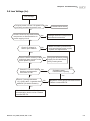
00: Operate disabled.
01: Operate with a standard motor.
02: Operate with a special motor.
02
06-07
Electronic Thermal
Characteristic
30~600 Sec
60
06-08
Low Current Detection 00~100% (00 disabled)
Level
06-09
Low Current Detection 0.1~ 3600.0 Sec
Time
06-10
Low Current Detection 00: Warn and Ramp to stop
Treatment
01: Warn and Coast to stop
02: Warn and keep operating
06-11
Present Fault Record
06-12
Second Most Recent
Fault Record
06-13
Third Most Recent
Fault Record
06-14
Fourth Recent Fault
Record
4-12
00
10.0
01
00: No Fault
01: Oc (over-current)
02: Ov (over-voltage)
03: OH (over temperature)
04: OL (over load)
05: oL1 (over load 1)
06: EF (external fault)
07: Occ (IGBT module is abnormal)
08: CF3 (driver’s internal circuitry is
abnormal)
09: HPF (hardware protection failure)
10: OcA (over-current during acceleration)
11: Ocd (over-current during deceleration)
12: Ocn (over-current during steady state
operation)
13: GFF(Ground Fault)
14: Lv (Low voltage)
15: CF1 (CPU READ failure)
16: CF2 (CPU WRITE failure)
17: bb (Base Block)
18: OL2 (over load2)
19: Reserved
20: Code (software/password protection)
21: EF1 (Emergency stop)
22: PHL (phase-loss)
23: Lc (Low Current)
24: FbL(Feedback Loss)
25: Reserved
26: FANP (Fan Power Fault)
27: FF1 (Fan 1 Fault)
28: FF2 (Fan 2 Fault)
29: FF3 (Fan 3 Fault)
30: FF123 (Fan 1, 2, 3 Fault)
00
00
00
00
Revision July 2008, EG03, SW V1.06
Chapter 4 Parameters|
Parameter
Functions
Settings
Factory
Customer
Setting
31: FF12 (Fan 1, 2 Fault)
32: FF13 (Fan 1, 3 Fault)
33: FF23 (Fan 2, 3 Fault)
34: Fv (Gate Drive Low Voltage Protect)
35~40: Reserved
41: HPF1 (GFF hardware error)
42: HPF2 (CC,OC hardware error)
43: HPF3 (OC hardware error)
44: HPF4 (OV hardware error)
45: CF3.3 (U-phase error)
46: CF3.4 (V-phase error)
47: CF3.5 (W-phase error)
48: CF3.6 (OV or LV)
49: CF3.7 (Isum error)
50: CF3.8 (Temperature sensor error)
06-15
Parameter Reset
00~65535
09: Reset parameters (50Hz, 380)
10: Reset parameters (60Hz, 440)
00
06-16
Parameter Protection
Password Input
00~65535
00
06-17
Parameter Protection
Password Setting
00~65535
00: No password protection
00
Group 7 AC Drive and Motor Parameters
Parameter
Functions
Settings
Factory
Customer
Setting
07-00
Identity Code of AC
Drive
Display by model type
##
07-01
Rated Current of AC
Drive
Display by model type
##
07-02
Full-load Current of
Motor
30~120%
100%
07-03
No-load Current of
Motor
1~99%
30%
07-04
Auto Slip
Compensation Gain
0.0~3.0
0.0
Rated Slip Frequency
of Motor
0.00~20.00Hz
0.00
07-06
Auto Torque
Compensation Gain
0.0~10.0
0.0
07-07
Torque Compensation
Gain by Manually
0.0~10.0
0.0
07-05
Revision July 2008, EG03, SW V1.06
4-13
Chapter 4 Parameters|
Parameter
Functions
Settings
Factory
Customer
Setting
07-08
Calculate Total
Running Time of the
Motor (Min)
00 to 1439 Min
00
07-09
Calculate Total
Running Time of the
Motor (Day)
00 to 65535 Day
00
07-10
Electric Bill for One
Time
Read Only
07-11
Accumulated Electric
Bill (per currency unit)
Read Only
07-12
Accumulated Electric
Bill (per 104 currency
unit)
Read Only
Electric Rate (per
currency unit)
0.01 to 655.35
07-13
Read
Read
Read
0.6
Group 8 Special Parameters
Parameter
Functions
Settings
Factory
Customer
Setting
08-00
DC Braking Current
Level
00~100%
00
08-01
DC Braking Time
during Start-up
0.0~60.0 Sec
0.0
08-02
DC Braking Time
during Stopping
0.00~60.00 Hz
0.0
08-03
Start-point for DC
Braking
0.00~160.00 Hz
0.00
08-04
Momentary Power
Loss Operation
Selection
00: Disable
01: Trace from top downward
02: Trace from bottom upward
00
08-05
Maximum Allowable
Power Loss Time
0.1~5.0 Sec
2.0
08-06
Speed Search Time
0.1~5.0 Sec
0.5
08-07
Maximum Speed
Search Current
30~150%
110
08-08
BB speed search
method
00: Trace from top downward
01: Trace from bottom upward
00
08-09
Auto Restart Times
after Fault
00~10
00
08-10
Auto Restart Time after 00 to 60000 sec
Fault
4-14
600
Revision July 2008, EG03, SW V1.06
Chapter 4 Parameters|
Parameter
Functions
Settings
Factory
Customer
Setting
08-11
Operation Frequency
Inhibition 1 UP
0.00~160.00 Hz
0.00
08-12
Operation Frequency
Inhibition 1 DOWN
0.00~160.00 Hz
0.00
08-13
Operation Frequency
Inhibition 2 UP
0.00~160.00 Hz
0.00
08-14
Operation Frequency
Inhibition 2 DOWN
0.00~160.00 Hz
0.00
08-15
Operation Frequency
Inhibition 3 UP
0.00~160.00 Hz
0.00
08-16
Operation Frequency
Inhibition 3 DOWN
0.00~160.00 Hz
0.00
08-17
Automatic Energysaving
00: Energy-saving operation disabled
01: Energy-saving operation enabled
00
08-18
Automatic Voltage
Regulation (AVR)
00: AVR function enabled
01: AVR function disabled
02: AVR function disabled for deceleration
00
08-19
Software Setting of the 740V~820VDC
Braking Level (the
00:Disabled
action level of the
braking resistor)
760
08-20
Vibration
Compensation Factor
00
00~1000
Group 9 Communication Parameters
Parameter
Functions
Settings
Factory
Customer
Setting
09-00
Communication
Address
01-254
00:Disabled
01
09-01
Transmission Speed
(Baud Rate)
00: Baud rate 4800
01: Baud rate 9600
02: Baud rate 19200
03: Baud rate 38400
01
09-02
Transmission Fault
Treatment
00: Warn and keep operating
01: Warn and RAMP to stop
02: Warn and COAST to stop
03: No warning and no display
03
09-03
Over Time Detection
during Transmission
00: Disabled
01: Enabled
00
09-04
Communication
Format
00: 7-bit for ASCII
01: 8-bit for ASCII
02: 8-bit for RTU
00
Revision July 2008, EG03, SW V1.06
4-15
Chapter 4 Parameters|
Parameter
Factory
Customer
Setting
Settings
Even/Odd Parity and 00: None parity + 2 stop bit
Stopping Parity Setting 01: Even parity + 2 stop bit
02: Odd parity + 2 stop bit
03: None parity + 1 stop bit
04: Even parity + 1 stop bit
05: Odd parity + 1 stop bit
00
09-06
Communication
Bit0~1: 00: Disable
Operation Command 1
01: Stop
10: Start-up
11: JOG start-up
Bit2~3: Reserved
Bit4~5: 00: No function
01: FWD command
10: REV command
11: Change direction command
Bit6~7: 00: 1st step accel/decel speed
01: 2nd step accel/decel speed
10: 3rd step accel/decel speed
11: 4th step accel/decel speed
Bit8~11:
0000: Master speed
0001: 1st step speed
0010: 2nd step speed
0011: 3rd step speed
0100: 4th step speed
0101: 5th step speed
0110: 6th step speed
0111: 7th step speed
1000: 8th step speed
1001: 9th step speed
1010: 10th step speed
1011: 11th step speed
1100: 12th step speed
1101: 13th step speed
1110: 14th step speed
1111: 15th step speed
Bit12: Select Bit6~11 function
Bit13~15 Reserved
00
09-07
Communication
Frequency Setting
09-08
Communication
Bit0: 1: EF ON
Operation Command 2 Bit1: 1: Reset
Bit2: 0: BB OFF, 1: BB ON
Bit3~15: Reserved
09-05
4-16
Functions
0~160.00Hz
60.00
00
Revision July 2008, EG03, SW V1.06
Chapter 4 Parameters|
Group 10 PID Control Parameters
Parameter
Functions
Settings
Factory
Customer
Setting
10-00
Input Terminal for PID
Feedback
00: Disabled
01: Input via AI1
02: Input via AI2
03: Input via External Reference
00
10-01
PID Control Detection
Signal Reference
1.0-6550.0
10-02
PID Feedback Control 00: Normal (Err=SP-FB)
Method
01: Inverse (Err=FB-SP)
10-03
Proportional Gain (P)
0.0~10.0
1.0
10-04
Integral Time (I)
0.00~100.00 Sec
1.00
1000.0
00
10-05
Differential Time (D)
0.00~1.00 Sec
0.00
10-06
Upper Bound for
Integral Control
00~200%
100
10-07
Primary Low Pass
Filter Time
0.0~2.5 Sec
0.0
10-08
PID Feedback Signal
Range
0.01 to 10-01
600.0
10-09
PID Feedback Signal
Fault Treatment Time
0. 0~3600.0 Sec
0.0: Disabled
0.0
PID Feedback Signal
Fault Treatment
00: Warn and RAMP stop
01: Warn and COAST stop
02: Warn and keep operating
01
V/F Curve Selection
00: Determined by group 01
01: 1.5 power curve
02: 1.7 power curve
03: 2 power curve
04: 3 power curve
00
10-10
10-11
Revision July 2008, EG03, SW V1.06
4-17
Chapter 4 Parameters|
4.2 Parameter Settings for Applications
Speed Search
Applications
Windmill, winding
machine, fan and all
inertia load
Purpose
Restart freerunning motor
Functions
Before the free-running motor is
completely stopped, it can be restarted
without detecting motor speed. The AC
motor drive will auto search motor
speed and will accelerate when its
speed is the same as the motor speed.
Related
Parameters
02-11
02-12
08-04
08-05
08-06
08-07
DC Brake before Running
Applications
Purpose
When e.g. windmills,
Keep the freefans and pumps rotate running motor at
freely by wind or flow standstill.
without applying power
Functions
If the running direction of the freerunning motor is not steady, please
execute DC brake before start-up.
Related
Parameters
08-00
08-01
Energy Saving
Applications
Punching machines
and precision
machinery
Purpose
Energy saving and
less vibrations
Functions
Energy saving when the AC motor
drive runs at constant speed, yet full
power acceleration and deceleration
For precision machinery it also helps
to lower vibrations.
Related
Parameters
08-17
Multi-step Operation
Applications
Conveying machinery
Purpose
Functions
Cyclic operation by To control 15-step speeds and duration
multi-step speeds. by simple contact signal.
Related
Parameters
04-00~04-03
05-00~05-14
Switching acceleration and deceleration time
Applications
Auto turntable for
conveying machinery
4-18
Purpose
Functions
Switching
acceleration and
deceleration times
by external signal
Switching the multi-step
acceleration/deceleration by external
signals. When an AC motor drive
drives two or more motors, it can reach
high-speed but still start and stop
smoothly.
Related
Parameters
01-09~01-16
04-00~04-03
Revision July 2008, EG03, SW V1.06
Chapter 4 Parameters|
Overheat Warning
Applications
Air conditioner
Functions
Related
Parameters
When the AC motor drive overheats, it
uses a thermal sensor to generate a
overheat warning.
03-00
04-00~04-03
Functions
Related
Parameters
Purpose
Safety measure
Two-wire/three-wire
Applications
General application
Purpose
To run, stop,
forward and
reverse by external
terminals
FWD/STOP
FWD:("OPEN":STOP)
("CLOSE":FWD)
REV/STOP
REV:("OPEN": STOP)
("CLOSE": REV)
DCM
VFD-G
FWD:("OPEN":STOP)
("CLOSE":RUN)
RUN/STOP
REV:("OPEN": F WD)
("CLOSE": REV)
FWD/REV
DCM
STOP
02-05
04-00~04-03
RUN
VFD-G
FWD:("CLOSE":RUN)
EF: ("OPEN":STOP)
REV/FWD
REV:("OPEN": F WD)
("CLOSE": REV)
DCM
VFD-G
Operation Command
Applications
General application
Purpose
Selecting the
source of control
signal
Functions
Related
Parameters
Selection of AC motor drive control by
external terminals, digital keypad or
RS485.
02-01
04-00~04-03
Functions
Related
Parameters
Frequency Hold
Applications
General application
Purpose
Acceleration/
Hold output frequency during
deceleration pause Acceleration/deceleration
04-00~04-03
Auto Restart after Fault
Applications
Air conditioners,
remote pumps
Purpose
Functions
For continuous and
The AC motor drive can be
reliable operation
restarted/reset automatically up to 10
without operator
times after a fault occurs.
intervention
Revision July 2008, EG03, SW V1.06
Related
Parameters
08-09
08-10
4-19
Chapter 4 Parameters|
Emergency Stop by DC Brake
Applications
High-speed rotors
Purpose
Emergency stop
without brake
resistor
Functions
AC motor drive can use DC brake for
emergency stop when a quick stop is
needed without brake resistor. When
used often, take motor cooling into
consideration.
Related
Parameters
08-00
08-02
08-03
Over-torque Setting
Applications
Pumps, fans and
extruders
Purpose
To protect
machines and to
have continuous/
reliable operation
Functions
The over-torque detection level can be
set. Once OC stall, OV stall and overtorque occurs, the output frequency
will be adjusted automatically. It is
suitable for machines like fans and
pumps that require continuous
operation.
Related
Parameters
06-03~06-05
Upper/Lower Limit Frequency
Applications
Pump and fan
Purpose
Control the motor
speed within
upper/lower limit
Functions
When user cannot provide
upper/lower limit, gain or bias from
external signal, it can be set
individually in AC motor drive.
Related
Parameters
01-07
01-08
Skip Frequency Setting
Applications
Pumps and fans
Purpose
To prevent
machine vibrations
Functions
The AC motor drive cannot run at
constant speed in the skip frequency
range. Three skip frequency ranges
can be set. It is used to smooth
vibration at certain frequencies.
Related
Parameters
08-11~08-16
Carrier Frequency Setting
Applications
General application
4-20
Purpose
Low noise
Functions
The carrier frequency can be
increased when required to reduce
motor noise.
Related
Parameters
02-03
Revision July 2008, EG03, SW V1.06
Chapter 4 Parameters|
Output Signal during Running
Applications
General application
Purpose
Functions
Signal available to stop braking when
Provide a signal for the AC motor drive is running. (This
running status
signal will disappear when the AC
motor drive is free-running.)
Related
Parameters
03-00
Output Signal in Zero Speed
Applications
General application
Purpose
Functions
When the output frequency is lower
Provide a signal for than the min. output frequency, a
running status
signal is given for external system or
control wiring.
Related
Parameters
03-00
Output Signal at Master Frequency
Applications
General application
Purpose
Functions
When the output frequency is at the
master frequency (by frequency
Provide a signal for
command), a signal is given for
running status
external system or control wiring
(frequency attained).
Related
Parameters
03-00
Output signal for Over-torque
Applications
Pumps, fans and
extruders
Purpose
To protect
machines and to
have continuous/
reliable operation
Functions
When over-torque is detected, a
signal is given to prevent machines
from damage.
Related
Parameters
03-00
06-03
06-04
06-05
Output Signal for Low Voltage
Applications
General application
Purpose
Functions
When low voltage is detected, a signal
Provide a signal for
is given for external system or control
running status
wiring.
Related
Parameters
03-00
Output Signal at Desired Frequency
Applications
General application
Purpose
Functions
When the output frequency is at the
Provide a signal for desired frequency (by frequency
running status
command), a signal is sent by an
external system or control wiring.
Revision July 2008, EG03, SW V1.06
Related
Parameters
03-00
03-02
03-03
4-21
Chapter 4 Parameters|
Output Signal for Base Block
Applications
General application
Purpose
Functions
When executing Base Block, a signal
Provide a signal for
is sent by an external system or
running status
control wiring.
Related
Parameters
03-00
Overheat Warning for Heat Sink
Applications
General application
Purpose
For safety
Functions
When heat sink is overheated, it will
send a signal by an external system or
control wiring.
Related
Parameters
03-00
Multi-function Analog Output
Applications
General application
4-22
Purpose
Display running
status
Functions
The value of frequency, output
current/voltage can be read by
adding a frequency meter or
voltage/current meter.
Related
Parameters
03-05~03-09
Revision July 2008, EG03, SW V1.06
Chapter 4 Parameters|
4.3 Description of Parameter Settings
Group 0: User Parameters
: This parameter can be set during operation.
00 - 00 Software Version
Factory setting: Read Only
This parameter displays the software version of AC drive.
00 - 01 AC Drive Status Indication 1
Factory setting: Read Only
This parameter displays the AC drive status.
Code
00
AC Drive Status
Explanation
No fault occurred
01
oc
over current
02
ov
over voltage
03
oH
over temperature
04
oL
overload
05
oL1
electronic thermal relay
06
EF (external fault)
EF-DCM is closed
07
occ (AC drive IGBT fault )
IGBT short circuit protection
08
CF3 (CPU failure)
Abnormal A/D reading during self-check
09
HPF (hardware protection
failure)
Hardware protection function activated during self-check.
10
ocA (over current during
acceleration)
Output current exceeds protection level during
acceleration
11
ocd (over current during
deceleration)
Output current exceeds protection level during
deceleration
12
Ocn (over current during
steady state)
Output current exceeds protection level during steady
state operation.
13
GFF (ground fault)
Ground fault protection feature activated
14
Lv (under voltage)
Low input voltage
15
CF1
EEPROM input data is abnormal
16
CF2
EEPROM output data is abnormal
17
bb (base block)
BB is set and activated
18
oL2 (over load 2)
Output current exceeds rated motor current
19
Reserved
20
codE
software or password protection
21
EF1 (external emergency
stop)
EF1 (a multifunction-DCM is enabled)
Revision July 2008, EG03, SW V1.06
4-23
Chapter 4 Parameters|
Code
22
AC Drive Status
Explanation
PHL (phase loss)
Input power lacks phase.
3-phase input power is unbalance and exceeds
specification.
23
Lc (Low Current)
Low current detection during operation.
24
FbL(Feedback Loss)
Feedback signal is abnormal.
25
Reserved
26
FANP
Fan Power Fault
27
FF1
Fan 1 Fault
28
FF2
Fan 2 Fault
29
FF3
Fan 3 Fault
30
FF123
Fan 1, 2, 3 Fault
31
FF12
Fan 1, 2 Fault
32
FF13
Fan 1, 3 Fault
33
FF23
Fan 2, 3 Fault
34
Fv
Gate Drive Low Voltage Protect
35~40
Reserved
41
HPF1
GFF hardware error
42
HPF2
CC,OC hardware error
43
HPF3
OC hardware error
44
HPF4
OV hardware error
45
CF3.3
U-phase error
46
CF3.4
V-phase error
47
CF3.5
W-phase error
48
CF3.6
OV or LV
49
CF3.7
Isum error
50
CF3.8
Temperature sensor error
00 - 02 AC Drive Status Indication 2
Factory setting: Read Only
Display
4-24
Bit 0~1: 00: Run LED is off and stop led is on. (AC Drive stopping)
01: Run LED is blink and stop led is on. (AC Drive deceleration to
stop)
10: Run LED is on and stop led is blink. (AC Drive standby)
11: Run LED is on and stop led is off. (AC Drive running)
Bit 2: 1: Jog on.
Bit 3~4: 00: Rev LED is off and FWD led is on. (Forward)
01: Rev LED is blink and FWD led is on. (Reverse to Forward)
10: Rev LED is on and FWD led is blink. (Forward to Reverse)
11: Rev LED is on and FWD led is off. (Reverse)
Bit 5-7: Reserved
Revision July 2008, EG03, SW V1.06
Chapter 4 Parameters|
Bit 8: Master frequency source via communication interface
Bit 9: Master frequency source via analog
Bit10: Running command via communication interface
Bit11: Parameter locked
Bit12~15: Reserved
00 - 03 Frequency Setting (F) or Closed Loop Control Setting Point
Factory setting: Read Only
This parameter displays the frequency command set by the user.
00 - 04 Output Frequency (H)
Factory setting: Read Only
This parameter displays actual output frequency of the AC drive.
00 - 05 Output Current (A)
Factory setting: Read Only
This parameter displays actual output current of the AC drive.
00 - 06 DC-BUS Voltage (U)
Factory setting: Read Only
This parameter displays DC-BUS voltage of the AC drive.
00 - 07 Output Voltage (E)
Factory setting: Read Only
This parameter displays output voltage of the AC drive.
00 - 08 Output Power Factor (n)
Factory setting: Read Only
This parameter displays output power factor.
00 - 09 Output Power (kW)
Factory setting: Read Only
This parameter displays output power of the AC drive.
Revision July 2008, EG03, SW V1.06
4-25
Chapter 4 Parameters|
00 - 10 Feedback Signal Actual Value
Factory setting: Read Only
This parameter displays feedback signal value.
00 - 11 Feedback Signal (%)
Factory setting: Read Only
This parameter displays feedback signal value(%).
00 - 12 User Target Value (Low bit) uL 0-99.99
Factory setting: Read Only
00 - 13 User Target Value (High bit) uH 0-9999
Factory setting: Read Only
User Target Value = Actual output frequency (0-04) × User Defined Multiplier (02-10).
Maximum summed display of both parameters is 999999.99.
When User Target Value <=99.99, 00-12=0.
00 - 14 PLC Time
Factory setting: Read Only
This parameter displays remaining time of PLC each step.
00 - 15 Output Reactive Power (KVAR)
Factory setting: Read Only
4-26
This parameter displays reactive power of AC drives.
Revision July 2008, EG03, SW V1.06
Chapter 4 Parameters|
Group 1: Basic Parameters
01 - 00 Maximum Output Frequency
Settings
50.00~160.00Hz
Factory Setting: 60.00
This parameter determines the AC drives maximum output frequency. All master frequency
commands set by the keypad or analog inputs are limited by this parameter. The analog
commands (ACI1 and ACI2) may be scaled to correspond to the output frequency range.
(Please refer to 04-05~04-12.)
01 - 01 Maximum Voltage Frequency (Base Frequency)
Settings
0.10~160.00 Hz
Factory Setting: 60.00
This parameter sets the frequency, where the maximum output voltage (Pr. 01-02) will be
reached. The output frequency may exceed this setting, but the output voltage doesn’t
increase beyond this point. This parameter should be set according to the rated frequency of
the motor as indicated on the motor nameplate.
If this parameter setting is smaller than the rated frequency of the motor, nuisance over current
faults or damage to the AC drive may occur.
If this parameter setting is greater than the rated frequency of the motor, the motor will
encounter torque loss.
01 - 02 Maximum Output Voltage
Settings
0.2V ~ 510.0V
Factory Setting: 440.0
This parameter determines the Maximum Output Voltage of the AC drive. This parameter
setting should be set according to rated voltage of the motor as indicated on the motor
nameplate. If rated voltage of the motor is 440V, this parameter must be set to 440V. If rated
voltage of the motor is 380V, this parameter must be set to 380V.
If this setting is greater than the rated voltage of the motor, nuisance over current faults or
damage to the AC drive may occur.
01 - 03 Mid-point Frequency
Settings
0.10~160.00 Hz
Factory Setting: 3.00
This parameter sets the Mid-point Frequency of the V/F curve.
This parameter must meet the following argument. Pr.1-01 >= Pr.1-03 >= Pr.1-05.
Revision July 2008, EG03, SW V1.06
4-27
Chapter 4 Parameters|
01 - 04 Mid-point Voltage
Settings
0.2V~510.0V
Factory Setting: 11.0
This parameter sets the Mid-point Voltage of the V/F curve.
This parameter must meet the following argument. Pr.1-02 >= Pr.1-04 >= Pr.1-06.
01 - 05 Minimum Output Frequency
Settings
0.10~20.00 Hz
Factory Setting: 3.00
This parameter sets the Minimum Output Frequency of the AC drive. This parameter must be
lower than or equal to the Mid-point frequency.
01 - 06 Minimum Output Voltage
Settings
0.2V~100.0V
Factory Setting: 11.0
This parameter sets the Minimum Output Voltage of the AC Drive. The parameter must be
lower than or equal to the Mid-point Voltage.
01 - 07 Upper Bound Frequency
Settings
0.00~160.00 Hz
Factory Setting: 60.00
This parameter will limit the maximum output frequency of AC drive. If slip compensation
(Pr.07-02~07-05) or feedback control (Pr.10-00~10-09) are enabled, the output frequency of
AC drive may exceed the Master Frequency Command, but it will continue to be limited by this
parameter setting.
01 - 08 Lower Bound Frequency
Settings
0.00~160.00 Hz
Factory Setting: 0.00
This parameter will limit the minimum output frequency. Any Master Frequency Command
below Pr.1-08, will result in an output equal to Pr.1-08.
Upon a start command, the drive will accelerate from Pr.1-05 Minimum Output Frequency to
the Master Frequency Command point.
4-28
Revision July 2008, EG03, SW V1.06
Chapter 4 Parameters|
Output voltage
01-02
01-04
01-06
01-05
01-08
01-03 01-01
01-00
01-07
Output Frequency
01 - 09
Acceleration Time 1
Unit: 0.1sec
01 - 10
Deceleration Time 1
Unit: 0.1sec
01 - 11
Acceleration Time 2
Unit: 0.1sec
01 - 12
Deceleration Time 2
Unit: 0.1sec
01 - 13
Acceleration Time 3
Unit: 0.1sec
01 - 14
Deceleration Time 3
Unit: 0.1sec
01 - 15
Acceleration Time 4
Unit: 0.1sec
01 - 16
Deceleration Time 4
Unit: 0.1sec
01 - 17
JOG Acceleration Time
Unit: 0.1sec
01 - 18
JOG Deceleration Time
Unit: 0.1sec
Settings
0.1~3600.0 Sec
Factory Setting: 10.0/60.0
Factory setting for 30HP and higher models is 60.0 seconds.
Acceleration time is the time required for the AC drive to ramp from 0 Hz to its Maximum
Output Frequency (Pr.1-00). Deceleration time is the time required for the AC drive to
decelerate from Maximum Output Frequency (Pr.1-00) down to 0 Hz.
An Acceleration or Deceleration time that is too quickly, may cause the AC drives protection
features to enable (over-current stall prevention during Accel 06-01 or over-voltage stall
prevention 06-00). If this occurs, the actual Accel/Decel time will be longer than this setting.
Warning: An acceleration or deceleration that is too quickly, may cause excess loads on the
AC drive and may permanently damage the drive.
If you want to decelerate the AC drive in short time period, we recommend adding an external
braking module and braking resistor.
You can set 1st to 4th Accel/Decel time via multi-function input terminals 04-00 to 04-03.
Revision July 2008, EG03, SW V1.06
4-29
Chapter 4 Parameters|
01 - 19
JOG Frequency
Settings
Unit: 0.1sec
0.0 Hz~160.00 Hz
Factory Setting: 6.00
When the JOG function is to be utilized, users need to use the multi-function input terminals
(Pr. 04-00 to 04-03 set to 07) or the JOG key on keypad. Once a JOG command is initiated,
the AC drive will accelerate from the Minimum Output Frequency (Pr.01-05) to the JOG
frequency (Pr.01-19).
The accel/decel time of the JOG operation is determined by the JOG accel/decel speed
(Pr.01-17 and 01-18).
When the drive is in operation, the JOG command is disabled.
01 - 20 S Curve Delay Time in Accel
01 - 21 S Curve Delay Time in Decel
Settings
0.00~2.50sec
Factory Setting: 0.00
These parameters enable the S curve. The longer the S curve time period the smoother the
transition between speeds.
01 - 22
Modulation Index
Settings
Unit: 0.1
0.90~1.20
Factory Setting: 1.00
This parameter sets the ratio of the Maximum Output Voltage to the input voltage.
The Maximum Output Voltage (Pr.01-02) is normally limited to the input voltage. With the
Modulation Index parameter, the user is able to increase the output voltage beyond the
incoming line voltage.
A Modulation Index of 1, defines the Maximum Output Voltage (Pr. 1-02) is equal to the input
voltage.
A Modulation index of 1.2, defines the Maximum Output Voltage (Pr. 1-02) is 20% higher than
in the input voltage. Please note, the output voltage wave form will be distorted due to
harmonics and may increase torque ripple and noise in the motor.
01 - 23 Accel/Decel Time Unit
Factory Setting: 01
Settings
4-30
00: Unit is 1 Sec
01: Unit is 0.1 Sec
02: Unit is 0.01 Sec
This parameter sets the resolution of accel/decel time (Pr.01-09 to 01-18).
Revision July 2008, EG03, SW V1.06
Chapter 4 Parameters|
A high resolution decreases the accel/decel time range as shown in the following chart.
01-23
Accel/Decel time unit
00
1 Sec
1~36000 Sec
01
0.1 Sec
0.1~3600.0 Sec
02
0.01 Sec
0.01~360.00 Sec
Revision July 2008, EG03, SW V1.06
Accel/Decel time range
4-31
Chapter 4 Parameters|
Group 2: Operation Method Parameters
02 - 00
Source of Frequency Command
Factory Setting: 00
Settings
00: via keypad
01: via analog input AI1 (10bit)
02: via analog input AI2 (10bit)
03: via RS485 serial communication (RJ-11)
04: via External Reference
Settings:
00: Frequency command source is the keypad. User may use UP/DOWN keys to adjust the
frequency command. Also if the Multi-Function Input terminals (Pr.04-00 to 04-03) are set
to 13 or 14, their function will be the same as the UP/DOWN keys.
01: Frequency command source is the analog input terminal AI1.
02: Frequency command source is the analog input terminal AI2.
03: Frequency command source is the RS485 serial communication.
04: Frequency command source depends on the setting of Pr. 04-20.
02 - 01
Source of Operation Command
Settings
Factory Setting: 00
00: Controlled by the digital keypad
01: Controlled by the external terminals, keypad STOP enabled.
02: Controlled by the external terminals, keypad STOP disabled.
03: Controlled by the RS-485 communication interface, keypad STOP
enabled.
04: Controlled by the RS-485 communication interface, keypad STOP
disabled.
This parameter sets the operation command source of the AC drive.
02 - 02 Stop Method
Factory Setting: 00
Settings
00:Stop = ramp to stop, E.F. (External Fault) = coast to stop
01:Stop = coast to stop, E.F. = coast to stop
02:Stop = ramp to stop, E.F. = ramp to stop
03:Stop = coast to stop, E.F. = ramp to stop
Ramp: The AC drive decelerates the motor to minimum output frequency according to the
deceleration time setting.
4-32
Revision July 2008, EG03, SW V1.06
Chapter 4 Parameters|
Coast: The AC drive output instantly stops upon command and the motor free spins until it
comes to a complete stop.
External Fault may be enabled by the EF terminal or a Multi-Function terminal. Please refer to
Pr.04-00 to 04-03.
Output
Frequency
Frequency
Output
Frequency
Motor
speed
Frequency
Motor
Speed
Time
Operation
Command
RUN
Stops according
to deceleration
time
STOP
Operation
Command
Time
RUN
Ramp
02 - 03
STOP
Coast
PWM Carrier Frequency Selections
Settings
Free running
to stop
7.5~10HP: 4000~6000Hz
Factory Setting: 6000
15~30HP: 3000~6000Hz
Factory Setting: 6000
40~125HP: 2000~6000Hz
Factory Setting: 4000
150~300HP: 2000~4000Hz
Factory Setting: 4000
This parameter sets the carrier frequency of PWM output. The factory setting and setting
range depend on the model type.
When the temperature of the heat sink is greater than its limit, the AC drive will automatic
lower the carrier frequency to avoid over heating the AC drive.
The Carrier frequency of the PWM output has a signification influence on the electromagnetic
noise, heat dissipation of the AC drive, and the acoustic noise to the motor as shown in the
following chart.
Carrier
Frequency
Acoustic
Noise
Electromagnetic
Noise
Leakage
Current
Heat
Dissipation
Signification
Minimal
Signification
Signification
Signification
Minimal
Signification
Minimal
Minimal
Minimal
When the carrier frequency is low, current ripple of the AC drive is large. This may result in a
current display value greater than the actual value.
Revision July 2008, EG03, SW V1.06
4-33
Chapter 4 Parameters|
02 - 04 Forward/Reverse Enabled
Factory Setting: 00
Settings
00: Forward/Reverse enabled
01: Reverse disabled
02: Forward disabled
This parameter enables the direction of the AC drive.
02 - 05 2-wire/3-wire Operation Control Modes
Factory Setting: 00
Settings
00: 2-wire (#1), FWD / STOP, REV / STOP
01: 2-wire (#2), RUN/STOP, FWD/REV
02: 3-wire operation
This parameter sets the operation mode when operating by external terminals.
Please refer to 02-01.
02-05
External Terminal
00 (2-wire #1)
FWD / STOP
REV / STOP
FWD/STOP
FWD :("O PEN":STOP)
REV/STOP
REV: ("OPEN ":S TOP)
01 (2-wire #2)
REV / FWD
RUN / STOP
RUN/STOP
("CLO SE":FWD)
DCM
("CLOSE ":REV)
F WD :("OPEN":STOP)
("CLOSE":RUN)
REV :("OPEN":FWD)
FWD/REV
DCM
STOP
RUN
F WD ("CLOSE ":RUN)
EF
02 3-wire
FWD/REV
("CLOSE":REV)
("OPEN":S TOP)
REV ("OPEN ":FW D)
DCM
("CLOSE ":R EV)
VFD-G
02 - 06 Line Start Lockout
Factory Setting: 01
Settings
00: Disabled
01: Enabled
When enabled, the AC drive will not start when powered up with a run command applied. The
AC drive must see the run command transition from stop to run after power up. When Line
Start Lockout is disabled (also known as Auto-Start), the AC drive will start when powered-up
with run commands applied.
4-34
Revision July 2008, EG03, SW V1.06
Chapter 4 Parameters|
02 - 07 Reserved
02 - 08
Start-up Display Selection
Factory Setting: 00
Settings
Bit0~1: 00 = F LED
01 = H LED
10 = U LED (special display)
11 = Fwd / Rev
Bit2: 0 = Fwd LED / 1 = Rev LED
Bit3~5: 000 = 1st 7-step
001 = 2nd 7-step
010 = 3rd 7-step
011 = 4th 7-step
100 = 5th 7-step
Bit6~7: Reserved
This parameter determines the display on keypad after each power up.
To program this parameter the user must first generate a Hex value with the information above.
Then using the Hex to Decimal conversion to find the corresponding Decimal value and enter it
into this parameter.
For example, a setting of 21 (decimal 21= hex 010101) will display the “H” and “REV” LEDs
and the cursor will stay at the 3rd 7-step display upon power up.
When setting to U LED, please refer to 02-09.
02 - 09
Special Display
Factory Setting: 00
Settings
00: A displays output current of AC drive
01: U displays DC-Bus voltage of AC drive
02: E displays RMS of output voltage
03: P displays feedback signal
04: PLC display auto procedure state
This parameter chooses the display on the keypad immediately following the “U” user defined
setting.
“MODE” key will scroll from “F”, “H”, “U”, (Pr. 02-09), FWD, and back to “F”.
Users may also use the “LEFT” key on the digital keypad to switch display content.
Revision July 2008, EG03, SW V1.06
4-35
Chapter 4 Parameters|
02 - 10
User Defined Coefficient
Settings
Unit: 0.01
0.01~160.00
Factory Setting: 1.00
When this parameter is set, the “H “display value = actual output frequency of AC drive x 0210.
If output frequency of AC drive is 90Hz, set 02-10 to 2.5. When H LED lights, the value on the
display is 225.00.
02 - 11
Flying Start
Factory Setting: 00
Settings
00: Disabled
01: Enabled (DC braking disabled)
When the AC drive starts into a running motor (Flying Start), it may cause an over current on
the drive and may damage the motor. Using speed search upon start-up will allow the drive to
slowly find the motor speed, smoothly take control of the motor, and bring it to command
speed.
If the Flying Start feature is enabled upon start-up, the DC braking 08-01 will be disabled.
02 - 12
Flying Start Frequency
Factory Setting: 00
Settings
02 - 13
00: Begin search from Master Frequency Command
01: Begin search from Maximum Frequency (Pr.01-00)
Master Frequency Memory Setting
Factory Setting: 01
Settings
00: Do not remember the last known frequency
01: Remember the last known frequency
If this parameter is set to 00: The AC drive will not store the last known master frequency
command, after power is removed.
If this parameter is set to 01: The AC drive will memorize the last known master frequency
command after power off. Upon power up the last known frequency is displayed.
After a fault, the AC drive will always remember the last know master frequency command.
This feature is only enabled when Pr. 02-00 is set for 0 or 4.
4-36
Revision July 2008, EG03, SW V1.06
Chapter 4 Parameters|
Group 3: Output Function Parameters
03 - 00 Multi-function Output terminal 1 (Relay)
Settings
Setting
00-21
Functions
Factory Setting: 01
Descriptions
00
Disabled
01
Indication during
operation
The corresponding output will be closed during operation
(including DC braking time).
02
Master frequency
attained
The corresponding output will be closed when output
frequency reaches master frequency command.
03
Zero Speed (including
shutdown)
The corresponding output will be closed when the AC drive
has no output voltage signal.
04
Over-torque
The corresponding output relay will be closed when the AC
drives output current exceeds the over-torque detection
level 06-04.
05
External Fault
The corresponding output will be closed when the EF is
enabled. (Pr. 04-00 to 04-03)
06
Low voltage detection
The corresponding output will be closed when the DC Bus
voltage drops below our threshold. The keypad will display
“Lu”.
07
Operation Mode
indication
The corresponding output will be closed when the AC
drives “Operation Command” is controlled by the external
terminals.
08
Fault Indication
The corresponding output will be closed when AC drive
has experienced a fault.
09
Master Frequency
Attained 1
The corresponding output will be closed when the AC
drives output frequency exceeds (Pr.03-08) Master
Frequency Attained 1.
10
Master Frequency
Attained 2
The corresponding output will be closed when the AC
drives output frequency exceeds (Pr.03-09) Master
Frequency Attained 2.
11
Over Temperature
indication
The corresponding output will be closed when the AC drive
temperature exceeds its rating.
12
Drive Ready
The corresponding output will be closed the when the AC
drive is ready and has no faults.
13
External Emergency Stop
(EF1)
The corresponding output will be closed when multifunction input terminals (Pr.04-00 to 04-03) are set to
emergency stop and then activated.
14
Software braking output
The corresponding output will be closed when the AC
drives DC bus voltage exceeds (Pr.08-19) the braking
level.
15
OL or OL1 overload
warning
The corresponding output will be closed upon an overload
(OL or OL1) fault.
16
Low current indication
The corresponding output will be closed when the AC
drives output current is lower than the Low Current setting
(Pr.06-08).
Revision July 2008, EG03, SW V1.06
4-37
Chapter 4 Parameters|
Setting
Functions
Descriptions
17
PID feedback error
indication
The corresponding output will be closed when the PID
feedback signal has an error.
18
Auto Running Command
The Output will be closed when PLC Program is running.
19
1-Step Running
Completed
The Output will be closed for 0.5 sec when each multi-step
speed is attained.
20
Auto Running Completed
The output will be closed for 0.5 sec when the PLC
program cycle has completed
21
Auto Running Paused
The output will be closed when PLC operation is paused.
Standard relay specifications = 10A/250VAC or 12A/24VDC.
Relay delay time is 5~10 msec.
03 - 01 Reserved
03 - 02 Master Frequency Attained 1
Unit: 0.01
03 - 03 Master Frequency Attained 2
Unit: 0.01
Settings
0.00~160.00 Hz
Factory Setting: 0.00
An output relay may be programmed to activate when the output frequency exceeds the
desired attained frequency setting of these two parameters.
There is a
± 2Hz window of operation. If the master frequency attained is 20Hz and the output
frequency exceeds 20Hz, the corresponding output relay will be “closed”. When the output
frequency is less than 18Hz, the corresponding output relay will be “opened” as the following
diagram shows.
Frequency
2Hz
2Hz
2Hz
4Hz
Master
frequency 1
Frequency
command
Master
frequency 2
Time
Output frequency
Master frequency
2 attained
Master frequency
1 attained
Master frequency
attained
4-38
Revision July 2008, EG03, SW V1.06
Chapter 4 Parameters|
03 - 04 DC Fan Control
Factory Setting: 00
Settings
00: Fan runs on power up.
01: Fan begins upon a RUN command. Fan stops 1 minute after a STOP
command.
02: Fan begins upon a RUN command. Fan stops after a STOP command
03: Fan is controlled by temperature. Fan will be started at approximate
60°C.
This parameter determines DC fan control method.
03 - 05 Analog Output 1, (AFM1) 0~10Vdc
Factory Setting: 00
03 - 06 Analog Output 2, (AFM2) 0/4~ 20mA
Factory Setting: 01
Settings
00: Output frequency
01: Output current
02: Output voltage
03: Frequency command
04: Power factor loading
These parameters select the content of the analog output signals AFM1 and AFM2.
Setting 00: 0-10V = 0 - (Pr.01-00)
Setting 01: 0-10V = 0 - (Double rated current)
Setting 02: 0-10V = 0 - (Pr.01-02)
Setting 03: 0-10V = 0 - Master Freq. command
Setting 04: 0-10V = 0.0 - output power factor 1.0
When using 0-20mA output, please refer to Pr. 3-14.
Maximum impedance loading of analog output 2 (AFM2) can’t be greater than 500 ohms.
03 - 07
03 - 08
Analog Output Gain 1
Analog Output Gain 2
Settings
01~200%
Factory Setting: 100
These parameters are to determine analog output gain.
The analog output is limited to 10V and 20mA. The gain is designed to offer a normally small
output signal to be enlarged for easier viewing on a meter.
Revision July 2008, EG03, SW V1.06
4-39
Chapter 4 Parameters|
03 - 09 Analog Output 2 Selection
Factory Setting: 01
Settings
4-40
00: 0~20mA
01: 4~20mA
This parameter selects the output range of Analog Output 2 (AFM2).
Revision July 2008, EG03, SW V1.06
Chapter 4 Parameters|
Group 4: Input Function Parameters
04 - 00 Multi-function Input terminal 1
Factory Setting: 01
04 - 01 Multi-function Input terminal 2
Factory Setting: 02
04 - 02 Multi-function Input terminal 3
Factory Setting: 03
04 - 03 Multi-function Input terminal 4
Settings
Setting
00~31
Functions
Factory Setting: 04
Descriptions
00
Disabled
All unused terminals should be set to 00, to assure they
have no effect on drive operation.
01
Multi-Speed terminal 1
02
Multi-Speed terminal 2
Allows selection of the 15 multi-step speeds. Please refer
to 05-00 to 05-14 to program the 15 step speeds.
03
Multi-Speed terminal 3
04
Multi-Speed terminal 4
05
Reset (NO)
06
Reset (NC)
07
Jog operation (JOG)
Enables the JOG command. Works identical to the JOG
key on the digital keypad.
08
Accel/Decel disable
Stops the acceleration or deceleration of the AC drive. AC
drive then maintains a constant speed.
09
1st and 2nd Accel/Decel
selection
10
3rd and 4th Accel/Decel
selection
A corresponding terminal set to value 09 and closed
selects Accel/Decel time 2. A corresponding terminal set
to value 10 and closed selects Accel/Decel time 3.
Accel/Decel time 4 is selected when both terminals are
closed.
11
B.B. (NO) input
12
B.B. (NC) input
13
Increase Frequency
14
Decrease Frequency
15
Emergency stop (NO)
16
Emergency stop (NC)
17
KEYPAD(open),
EXT(close)
Revision July 2008, EG03, SW V1.06
Clears (Reset) a fault and returns the AC drive to normal
operation.
Enables the base block (pause) function.
Please refer to Pr.08-08, for base block functions.
Enables the external terminals to increase or decrease the
Master Frequency command each time an input is
received. Terminals are not active during a stop
command.
Generates an external fault (EF1). The function is identical
to the external terminal (EF).
External selection of the Operation Command Source.
(Keypad = terminal open) or (External terminals = terminal
closed). This setting is valid when Pr.02-01 is set to 00.
Otherwise, the Operation Command Source will follow the
setting in Pr.02-01.
4-41
Chapter 4 Parameters|
Setting
Functions
Descriptions
18
PID disabled
Disable PID feedback control and operate via Master
Frequency Command source Pr.02-00.
19
Run PLC Program
20
Pause PLC Program
Parameter value 32 programs Multi-Function Input
Terminal to enable the AC drive internal PLC program.
Parameter value 33 programs an input terminal to pause
the PLC program.
Note: Pr.05-00 to Pr.05-16 defines the PLC program.
21
1st Output Frequency
Gain (Pr.04-30)
Output frequency multiplies a gain (Pr.04-30),
H=F*(Pr.04-30)
22
2nd Output Frequency
Gain (Pr.04-31)
Output frequency multiplies a gain (Pr.04-31),
H=F*(Pr.04-31)
23
3rd Output Frequency
Gain (Pr.04-32)
Output frequency multiplies a gain (Pr.04-32),
H=F*(Pr.04-32)
04 - 04 Digital Input Terminal Response Time
Settings
01~20
Factory Setting: 01
This parameter selects the response time of digital input terminals MI1 to MI4, EF and FWD.
AC drive will scan the digital input terminals once every 2msec. During each scan the drive will
check the status of each terminal (open or closed).
In noisy environments, it would be advantageous to verify the terminal status several times
before executing a new command, nearly eliminating false signals.
Example: If Pr.04-04 is set to 4, the AC drive will confirm the terminal status (4+1 = 5) 5 times
before a change is made. This correlates to an 8~10msec time response from input command
to execution.
It is not recommended to set this parameter to 00, since interference may cause improper
operation of the AC drive.
04 - 05 Minimum AI1 Analog Input
Settings
0 ~ 100%
04 - 06 Maximum AI1 Analog Input
Settings
0 ~ 100%
04 - 07 Minimum Output that corresponds to AI1
Settings
0.00~100.00%
04 - 08 Maximum Output that corresponds to AI1
Settings
4-42
0.00~100.00%
Unit: 1
Factory Setting: 0
Unit: 1
Factory Setting: 100
Unit: 0.01
Factory Setting: 0.00
Unit: 0.01
Factory Setting: 100.00
Revision July 2008, EG03, SW V1.06
Chapter 4 Parameters|
04 - 09 Minimum AI2 Analog Input
Settings
0 ~ 100%
Unit: 1
Factory Setting: 0
04 - 10 Maximum AI2 Analog Input
Settings
0 ~ 100%
04 - 11 Minimum Output that corresponds to AI2
Settings
0.0~100.0%
04 - 12 Maximum Output that corresponds to AI2
Settings
0.0~100.0%
Unit: 1
Factory Setting: 100
Unit: 0.01
Factory Setting: 0.00
Unit: 0.01
Factory Setting: 100.00
04 - 13
1st AI1 Gain
Unit: 0.1
04 - 14
2nd AI1 Gain
Unit: 0.1
04 - 15
3rd AI1 Gain
Unit: 0.1
04 - 16
4th AI1 Gain
Unit: 0.1
04 - 17
5th AI1 Gain
Unit: 0.1
04 - 18
1st AI2 Gain
Unit: 0.1
04 - 19
2nd AI2 Gain
Unit: 0.1
04 - 20
3rd AI2 Gain
Unit: 0.1
04 - 21
4th AI2 Gain
Unit: 0.1
04 - 22
5th AI2 Gain
Settings
0.0~100.0%
Unit: 0.1
Factory Setting: 100.0
These parameters set analog input value and maximum output frequency (01-00, used in
open-loop control) or the corresponding function of the detection reference value (10-01, used
in PID closed-loop control). They divide output frequency into several sections according to
Pr.04-26 to Pr.04-29. There is an independent gain and minimum output frequency in every
section. We can reduce inferior products and improve working efficiency via parameter
modification. For example, we set frequency via two groups analog input terminals. When the
frequency we set is 0-15Hz and the gain is 50%, the minimum output frequency will be 5Hz;
when the frequency we set is 15-35Hz and the gain is 80%, the minimum output frequency will
be 15Hz; when the frequency we set is 35-50Hz and the gain is 150%, the minimum output
frequency will be 35Hz as the following diagram shows.
Revision July 2008, EG03, SW V1.06
4-43
Chapter 4 Parameters|
H
01-08
01-05 01-08 04-26 04-27 04-28 04-29 01-00
AI1 Gain
04-13
04-14 04-15 04-16 04-17
AI2 Gain
04-18
04-19 04-20 04-21 04-22
F
04 - 23 Analog Input Delay AI1
Unit: 0.01
04 - 24 Analog Input Delay AI2
Settings
Unit: 0.01
0.00 ~ 10.00 Sec
Factory Setting: 0.50
These parameters select the time constant for the analog input signal filter. A properly
adjusted time constant may help filter noise on the analog input terminals.
If the input delay is set too long, the system may experience oscillation. Be careful setting
these parameters.
04 - 25 Summation of External Frequency Sources
Factory Setting: 00
Settings
00: disabled
01: AI1*(AI1 Gain)+AI2*(AI2 Gain)
02: AI1*(AI1 Gain)-AI2*(AI2 Gain)
03: AI1*(AI1 Gain)*AI2*(AI2 Gain)
04: Reserved
05: Communication master frequency +AI1*(AI1 Gain)
06: Communication master frequency +AI2*(AI2 Gain)
07: Max (AI1*(AI1 Gain), AI2*(AI2 Gain))
This parameter selects the terminals used for summation of the External Frequency Sources.
Setting 07 is used to compare AI1*(AI1 Gain) with AI2*(AI2 Gain). If AI1*(AI1 Gain) > AI2*(AI2
Gain), it indicates that command source is from AI1, otherwise is from AI2.
4-44
Revision July 2008, EG03, SW V1.06
Chapter 4 Parameters|
04 - 26
1st Analog Input Frequency Gain
04 - 27
2nd Analog Input Frequency Gain
Unit: 0.01
04 - 28
3rd Analog Input Frequency Gain
Unit: 0.01
04 - 29
4th Analog Input Frequency Gain
Settings
0.00~160.00Hz
Unit: 0.01
Unit: 0.01
Factory Setting: 0.00
These parameters divide output frequency into several sections. (Refer to Pr.04-22).
04 - 30
1st Output Frequency Gain
Unit: 0.1
04 - 31
2nd Output Frequency Gain
Unit: 0.1
04 - 32
3rd Output Frequency Gain
Settings
0.0~200.0%
Unit: 0.1
Factory Setting: 100.0
These parameters set output frequency gain. We can select the functions of 21st to 23rd via
multi-function terminal. When the multi-function terminal is active, output frequency multiplies a
gain, i.e. output frequency H=F*(Pr.04-30/04-31/04-32).
Revision July 2008, EG03, SW V1.06
4-45
Chapter 4 Parameters|
Group 5: Multi-step Speed Parameters
05 - 00
1st Step Speed Frequency
Unit: 0.01
05 - 01
2nd Step Speed Frequency
Unit: 0.01
05 - 02
3rd Step Speed Frequency
Unit: 0.01
05 - 03
4th Step Speed Frequency
Unit: 0.01
05 - 04
5th Step Speed Frequency
Unit: 0.01
05 - 05
6th Step Speed Frequency
Unit: 0.01
05 - 06
7th Step Speed Frequency
Unit: 0.01
05 - 07
8th Step Speed Frequency
Unit: 0.01
05 - 08
9th Step Speed Frequency
Unit: 0.01
05 - 09
10th Step Speed Frequency
Unit: 0.01
05 - 10
11th Step Speed Frequency
Unit: 0.01
05 - 11
12th Step Speed Frequency
Unit: 0.01
05 - 12
13th Step Speed Frequency
Unit: 0.01
05 - 13
14th Step Speed Frequency
Unit: 0.01
05 - 14
15th Step Speed Frequency
Settings
Unit: 0.01
0.00~160.00 Hz
Factory Setting: 0.00
The Multi-Function Input Terminals (refer to Pr.04-00 to 04-03) are used to select one of the
AC drive Multi-Step speeds. The speeds (frequencies) are determined by Pr.05-00 to 05-14
shown above.
05 - 15 PLC Mode
Factory Setting: 00
Settings
00
Disable PLC operation
01
Execute one program cycle only
02
Continuously execute program cycles
03
Execute one program cycle only and step by step
04
Continuously execute program cycles step by step
This parameter selects the mode of PLC operation for the AC drive. The AC drive will change
speeds and directions according to the user’s desired programming.
4-46
Revision July 2008, EG03, SW V1.06
Chapter 4 Parameters|
Example 1 (Pr.05-15 = 1): Execute one cycle of the PLC program. Its relative parameter
settings are:
Pr.05-00 to 05-14:
1st to 15th step speeds (sets the frequency of each step speed)
Pr.04-00 to 04-03:
Multi-Function Input Terminals (set one multi-function terminal as 32 - PLC
auto-operation).
Pr.03-00:
Multi-Function Output Terminals (set a Multi-Function Terminal as 34-PLC
running indication, 35-PLC step completed or 36-PLC program completed).
Pr.05-16:
Direction of the 1st to 15th step speeds.
Pr.05-17 to 05-31:
Operation time setting for each corresponding step speed.
Program operation
command
Program operation
indication
Step operation
indication
Program operation
fulfillment indication
Note: The above diagram shows one complete PLC operation cycle. To restart this cycle, turn the
multi-function input terminal that designed as PLC program off and on again.
Example 2 (Pr.05-15 = 2): Continuously executes program cycles:
The diagram above shows the PLC program stepping through each speed. Set Pr.05-15 to 2 for
continuous program execution. To stop the PLC program, one must either pause the function or turn
it off. (Refer to Pr.04-00 to 04-03 values 32 and 33).
Revision July 2008, EG03, SW V1.06
4-47
Chapter 4 Parameters|
Example 3 (Pr.05-15 = 3) Execute one cycle step by step:
The example below shows how the PLC can perform one cycle at a time, within in a complete cycle.
Each step will use the accel/decel times in Pr.01-09 to Pr.01-16. It should be noticed that the time
each step spends at its intended frequency is diminished, due to the time spent during accel/decel.
Frequency
PLC operation execution one cycle step by step
05-03
05-02
05-01
05-00
1
05-17
Program operation
command
OFF
Program operation
indication
OFF
2
t
05-18
3
t
05-19
4
t
Time
05-20
ON
ON
ONON
ON
Step operation
OFF
indication
05 - 16 PLC Forward/Reverse Motion
Settings
00 to 32767 (0:Forward, 1:Reverse)
Factory Setting: 00
This parameter controls the direction of motion for the Multi-Step Speeds Pr.05-00 to Pr.05-14
during PLC mode. All other direction commands are invalid during the PLC mode.
Note: The equivalent 15-bit number is used to program the forward/reverse motion for each of the 15
speed steps. The binary notation for the 15-bit number must be translated into decimal notation
and then entered.
4-48
Revision July 2008, EG03, SW V1.06
Chapter 4 Parameters|
Weights
Bit 15 14 13 12 11 10 9 8
7
6
5
4
3
2
1
0
0=Forward
1=Reverse
Direction of 1st speed for Pr.05-00
Direction of 2nd speed for Pr.05-01
Direction of 3rd speed for Pr.05-02
Direction of 4th speed for Pr.05-03
Direction of 5th speed for Pr.05-04
Direction of 6th speed for Pr.05-05
Direction of 7th speed for Pr.05-06
Direction of 8th speed for Pr.05-07
Direction of 9th speed for Pr.05-08
Direction of 10th speed for Pr.05-09
Direction of 11th speed for Pr.05-10
Direction of 12th speed for Pr.05-11
Direction of 1 3th speed for Pr.05-12
Direction of 14th speed for Pr.05-13
Direction of 15th speed for Pr.05-14
Weights
Bit
0
1
0
0
1 1
0 0
0
1
1
1
0
0
1
0
0=Forward
1=Reverse
Direction of Pr.05-00, 1st speed = Forward
Direction of Pr.05-01,2nd speed=Reverse
Direction of Pr.05-02 ,3rd speed=Forward
Direction of Pr.05-03 ,4th speed=Forward
Direction of Pr.05-04 ,5th speed=Reverse
Direction of Pr.05-05,6th speed=Reverse
Direction of Pr.05-06,7th speed=Reverse
Direction of Pr.05-07,8th speed=Forward
Direction of Pr.05-08,9th speed=Forward
Direction of Pr.05-09,10th speed=Forward
Direction of Pr.05-10,11th speed=Reverse
Direction of Pr.05-11,12th speed=Reverse
Direction of Pr.05-12, 13th speed=Forward
Direction of Pr.05-13,14th speed=Forward
14
13
Direction of Pr.05-14,15th speed=Reverse
2
1
The setting value = bit14x2 + bit13x2 +....+bit2x2 +bit1x2 +bit0x2
14
11
10
6
5
4
1
= 1x2 + 1x2 +1x2 +1x2 +1x2 +1x2 +1x2
=16384+2048+1024+64+32+16+2
=19570
Setting 05-16 =19570
NOTE:
14
2 =16384
9
2 =512
4
2 =16
13
2 =8192
8
2 =256
3
2 =8
Revision July 2008, EG03, SW V1.06
12
2 =4096
7
2 =128
2
2 =4
11
2 =2048
6
2 =64
1
2 =2
0
10
2 =1024
5
2 =32
0
2 =1
4-49
Chapter 4 Parameters|
05 - 17 Time Duration of 1st Step Speed
Unit: 1 /0.1sec
05 - 18 Time Duration of 2nd Step Speed
Unit: 1 /0.1sec
05 - 19 Time Duration of 3rd Step Speed
Unit: 1 /0.1sec
05 - 10 Time Duration of 4th Step Speed
Unit: 1 /0.1sec
05 - 21 Time Duration of 5th Step Speed
Unit: 1 /0.1sec
05 - 22 Time Duration of 6th Step Speed
Unit: 1 /0.1sec
05 - 23 Time Duration of 7th Step Speed
Unit: 1 /0.1sec
05 - 24 Time Duration of 8th Step Speed
Unit: 1 /0.1sec
05 - 25 Time Duration of 9th Step Speed
Unit: 1 /0.1sec
05 - 26 Time Duration of 10th Step Speed
Unit: 1 /0.1sec
05 - 27 Time Duration of 11th Step Speed
Unit: 1 /0.1sec
05 - 28 Time Duration of 12th Step Speed
Unit: 1 /0.1sec
05 - 29 Time Duration of 13th Step Speed
Unit: 1 /0.1sec
05 - 30 Time Duration of 14th Step Speed
Unit: 1 /0.1sec
05 - 31 Time Duration of 15th Step Speed
Settings
0.0~65500 Sec / 0.0~6550.0 Sec
Unit: 1 /0.1sec
Factory Setting: 0.0
Pr.05-17 to Pr.05-31 correspond to operation time of each step speed defined by Pr.05-00 to
Pr.05-14. The maximum setting 65500 seconds will be displayed as t6550. If it is displayed
t6550. that means 6550 seconds.
Note: If a parameter is set to “00” (0 sec), the corresponding step will be skipped. This is commonly
used to reduce the number of program steps.
4-50
Revision July 2008, EG03, SW V1.06
Chapter 4 Parameters|
05-07
Frequency
05-06
05-08
05-05
05-09
05-04
05-10
05-03
05-11
05-02
05-12
05-01
JOG Freq.
05-13 01-19
05-00
05-14
Master Speed
2 3 4 5 6 7 8 9 1011 12 131415
Run Signal
1st step speed Multi-function Terminal
Pr.04-00 to Pr.04-07 (MI1 to MI8 1)
2nd step speed Multi-function Terminal
Pr.04-00 to Pr.04-07 (MI1 to MI8 2)
ON
OFF
ON
OFF
3rd step speed Multi-function Terminal
Pr.04-00 to Pr.04-07 (MI1 to MI8 3)
OFF
4th step speed Multi-function Terminal
Pr.04-00 to Pr.04-07 (MI1 to MI8 4)
OFF
ON
ON
ON
ON
ON
ON
ON
ON
ON
ON
ON
ON
ON
OFF
ON
Jog Freq.
Multi-Step Speed via External Terminals
05 - 32 Time Unit Settings
Factory Setting: 00
Settings
00
1 Sec
01
0.1 Sec
This parameter determines the time unit for Pr.05-17~Pr.05-31.
Revision July 2008, EG03, SW V1.06
4-51
Chapter 4 Parameters|
Group 6: Protection Function Parameters
06 - 00 Over-voltage Stall Prevention
Factory Setting: 780.0
Settings
660.0V~820.0VDC
00: Disabled
This parameter selects the voltage level for the Over-Voltage Stall Prevention function.
During decelerations, the DC bus voltage may exceed its maximum allowable value due to
motor regeneration. When this function is enabled, the AC drive will stop decelerating and
maintain a constant output frequency. The AC drive will only resume deceleration when the
voltage drops below the preset value.
With moderate inertial loads, the over-voltage stall prevention will not occur and the
deceleration time should be equal to Pr.1-10. With high inertial loads, the AC drive will
automatically extend the deceleration time due to the step function shown below. If the
deceleration time is critical for the application, then dynamic braking resistors should be used.
Output frequency
Deceleration characteristic
when Over-voltage stall
prevention enabled
Frequency held
Time
Deceleration Time
06 - 01 Over-current Stall Prevention during Acceleration
Settings
20~250%
Unit: 1
Factory Setting: 150%
This parameter selects the percentage of allowable over-current during acceleration before the
stall prevention is enabled.
During acceleration, the AC drive output current may increase abruptly and exceed the value
specified by Pr.06-01 due to rapid acceleration or excessive load on the motor. When this
function is enabled, the AC drive will stop accelerating and maintain a constant output
frequency. The AC drive will only resume acceleration when the current drops below the value
set in Pr.06-01 (please see the graph below).
4-52
Revision July 2008, EG03, SW V1.06
Chapter 4 Parameters|
When the over-current stall prevention is activated, the acceleration time of the AC drive will
be longer than the time set in Pr. 01-09.
Over-current Stall
Prevention during
acceleration
Current
06-01
Output
frequency
Over-current stall
prevention during
acceleration,
frequency held
Time
Over-current Stall Prevention during Acceleration
06 - 02 Over-current Stall Prevention during operation
Settings
Unit: 1
20~250%
Factory Setting: 150%
This parameter selects the percentage of allowable over-current during operation before the
stall prevention function is enabled.
If the output current exceeds the value specified in Pr.06-02 when the drive is operating at
steady state speed, the drive will decrease its output frequency to prevent the drive from
faulting with an OC. Once the current falls below the value specified in Pr.06-02, the drive will
then accelerate to catch up with the command frequency.
Over-current Stall
Prevention during
operation 06-02
Current
Over-current Stall
Prevention during
operation, output
frequency decrease
Output
frequency
Time
Over-current Stall Prevention during Operation
Revision July 2008, EG03, SW V1.06
4-53
Chapter 4 Parameters|
06 - 03 Over-torque Detection Selection
Factory Setting: 00
Settings
00: Over-torque detection disabled.
01: Over-torque detection enabled during constant speed operation (OL2),
and operation continues.
02: Over-torque detection enabled during constant speed operation (OL2),
and operation halted.
03: Over-torque detection enabled during operation (OL2), and operation
continues.
04: Over-torque detection enabled during constant speed operation (OL2),
and operation halted.
This parameter selects the Over-torque Detection operation.
If this parameter is set to 01 or 02, over-torque detection will not occur during acceleration.
06 - 04 Over-torque Detection Level
Settings
30~150%
Unit: 1
Factory Setting: 110
This parameter sets the Over-torque Detection level based on the AC drive rated current.
06 - 05 Over-torque Detection Time
Settings
0.1~60.0 Sec
Unit: 0.1
Factory Setting: 0.1
This parameter selects the allowable time of Over-torque Detection before the AC drive faults
with an OL2.
When the output current exceeds Pr.06-04 for the time set in Pr06-05, AC drive will fault and
display “OL2” on the keypad.
06 - 06 Electronic Thermal Relay Selection
Factory Setting: 02
Settings
00: Operation disabled.
01: Operation with a standard motor (shaft mounted fan cooled).
02: Operation with a vector motor (non-fan cooled or self powered fan)
This parameter provides electronic thermal protection for the motor. When the output current
exceeds Pr.07-02 for the time set in Pr.06-07, the drive will fault with an OL1.
06 - 07 Electronic Thermal Characteristic
Settings
30~600 Sec
Unit: 1
Factory Setting: 60
This parameter selects the time required for the electronic thermal protection function to
activate.
4-54
Revision July 2008, EG03, SW V1.06
Chapter 4 Parameters|
When Pr.6-06 is set for 1 or 2 and the output current exceeds Pr.7-02 for the time set in Pr.607, the drive will fault with an OL1.
The common electronic thermal reaction time (150% output current for 1 minute) is shown in
the chart below. The actual reaction time will vary depending on output current.
5
Operation
Time(min)
60Hz or more
4
50Hz
3
10Hz
5Hz
2
1
0
Load
factor
(%)
20 40 60
80 100 120 140 160 180 200
06 - 08 Low Current Detection Level
Settings
00~100% (00 disabled)
Unit: 1
Factory Setting: 00
06 - 09 Low Current Detection Time
Settings
0.1~ 3600.0 Sec
Unit: 0.1
Factory Setting: 10.0
06 - 10 Low Current Detection Treatment
Factory Setting: 01
Settings
00: Warn and Ramp to stop
01: Warn and Coast to stop
02: Warn and keep operating
These parameters set the low current detection mode, time, and operation.
06 - 11 Present Fault Record
06 - 12 2nd Most Recent Fault Record
06 - 13 3rd Most Recent Fault Record
06 - 14 4th Recent Fault Record
Factory Setting: 00
Revision July 2008, EG03, SW V1.06
4-55
Chapter 4 Parameters|
Settings
00
No fault occurred
01
Over-current (oc)
02
Over-voltage (ov)
03
Overheat (oH)
04
Overload (oL)
05
Overload1 (oL1)
06
External fault (EF)
07
IGBT protection (occ)
08
CPU failure (CF3)
09
Hardware protection failure (HPF)
10
Over-current during acceleration (OcA)
11
Current exceeds 2 times rated current during decel. (ocd)
12
Current exceeds 2 times rated current during steady state
operation (ocn)
13
Ground fault (GFF)
14
Low voltage (Lv)
15
CPU READ failure (CF1)
16
CPU WRITE failure (CF2)
17
Base Block (bb)
18
Motor over load (oL2)
19
Reserved
20
Software/password protection (codE)
21
Emergency stop (EF1)
22
Phase-Loss (PHL)
23
Low-current (Lc)
24
Feedback Loss (FbL)
25
Reserved
26
Fan Power Fault (FANP)
27
Fan 1 Fault (FF1)
28
Fan 2 Fault (FF2)
29
Fan 3 Fault (FF3)
30
Fan 1, 2, 3 Fault (FF123)
31
Fan 1, 2 Fault (FF12)
32
Fan 1, 3 Fault (FF13)
33
Fan 2, 3 Fault (FF23)
34
Gate Drive Low Voltage Protect (Fv)
35~40 Reserved
41
4-56
GFF hardware error (HPF1)
Revision July 2008, EG03, SW V1.06
Chapter 4 Parameters|
42
CC,OC hardware error (HPF2)
43
OC hardware error (HPF3)
44
OV hardware error (HPF4)
45
U-phase error (CF3.3)
46
V-phase error (CF3.4)
47
W-phase error (CF3.5)
48
OV or LV (CF3.6)
49
Isum error (CF3.7)
50
Temperature sensor error (CF3.8)
06 - 15 Parameter Reset
Factory Setting: 00
Settings
00~65535
09: Reset parameters (50Hz, 380)
10: Reset parameters (60Hz, 440)
This parameter resets all parameters to the factory setting.
06 - 16 Parameter Protection Password Input
Settings
00~65535
Factory Setting: 00
This parameter allows the user to enter their password to unlock the Parameter Protection
feature. The password entered must match the value entered into Pr.6-17. After three invalid
password attempts, the drive will no longer allow any operation. The drive must then be
powered off and back on again.
After successfully entering the password, the user may change parameters as they wish.
Once the drive is powered off, the drive has locked the parameters again. To clear the
password, the user must enter the correct password in Pr.6-16 and then set Pr.6-17 to 00.
06 - 17 Parameter Protection Password Setting
Factory Setting: 00
Settings
00~65535
00: No password protection
This parameter allows the user to set a password for parameter protection. After entering a
password, Pr.6-17 will display 1.
Be sure to keep the password in a safe place. If the password is lost, please return the drive to
DELTA.
Revision July 2008, EG03, SW V1.06
4-57
Chapter 4 Parameters|
Group 7: AC Drive and Motor Parameters
07 - 00 Identity Code of AC Drive
Settings
Display by model type
Factory Setting: ##
This parameter displays the AC drive model code.
This parameter is read-only.
07 - 01 Rated Current of AC Drive
Settings
Display by model type
Factory Setting: ##
This parameter displays rated output current of the AC drive. The following chart may be used
to look up the identity code, current, and hp of your drive.
kW
5.5 7.5
11
15 18.5 22
30
37
45
55
75
90
110
132
160
185
220
HP
7.5
10
15
20
25
30
40
50
60
75
100 125 150
175
215
250
300
Pr.07-00
13
15
17
19
21
23
25
27
29
31
33
37
39
41
43
45
Rated Current (A)
13
18
24
32
38
45
60
73
91
110 150 180 220
260
310
370
460
35
Max. Carried Freq.
6kHz
6kHz
6kHz
4kHz
Min. Carried Freq.
4kHz
3kHz
2kHz
2kHz
Factory Setting
6kHz
6kHz
4kHz
4kHz
This parameter is read-only.
07 - 02
Full-load Current of Motor
Settings
30~120%
This parameter selects the full load current of the motor.
Pr7-02 = (full load motor current / drive rated current)
Unit: 1
Factory Setting: 100%
Example: If the rated current of AC drive is 150A, full-load current of motor is 120A, then Pr.702 should be set to 80%.
This parameter is used with slip compensation Pr.7-04 to Pr.7-05 and electronic thermal relay
Pr.6-06 to Pr.6-07. An incorrect setting will cause these functions to not work incorrectly and
may damage the motor and drive.
The full-load current of the motor must be equal to or less than (but not less than 50%) the
rated current of the AC drive.
4-58
Revision July 2008, EG03, SW V1.06
Chapter 4 Parameters|
07 - 03
No-load Current of Motor
Settings
1~99%
Unit: 1
Factory Setting: 30%
This parameter sets the no-load current of the motor.
Pr.7-03 = (no load current / drive rated current)
Example: If the rated current of the AC drive is 150A and no-load current of the motor is 40A,
then Pr.7-03 should be set to 27%.
This parameter is used with slip compensation Pr.7-04 and Pr.7-05. An incorrect setting will
cause the function to work incorrectly and may damage the motor and drive.
If the no-load current of the motor is unavailable, it may be found by running the motor with no
load and reading the current on the keypad display.
07 - 04
Auto Slip Compensation Gain
Settings
0.0~3.0
Unit: 0.1
Factory Setting: 0.0
This parameter is set to auto slip compensation gain.
Rotor speed of the motor (output frequency of AC drive) can’t synchronize due to induction
motor characteristic. The difference between synchronization speed and rotor speed is called
slip frequency. Slip frequency is in direct proportion with output torque and output current.
Therefore, slip compensation could make rotor speed and master frequency command the
same according output current (lo).
The equation of slip compensation is (07-05) X (07-04) X (Io-(07-03)) / ((07-02)-(07-03)). If
rated current of AC drive is 150A, full-load current of the motor is 120A, no-load current is 40A,
rated slip frequency is 5Hz and output current of AC drive is 100A. At this time, slip
compensation is (07-04) X 5 X (100-40) / (120-40) = 3.75 X (07-04). If 07-04 is set to 1.0 and
the compensation is 3.75. If master frequency command is set to 50Hz and output frequency is
53.75.
Output frequency after compensation is limited by 01-07 upper bound frequency. When using
slip compensation, 01-07 should be set to the suitable value.
When PID feedback control, slip compensation function will be disabled.
Unsuitable setting value may cause over compensation.
Revision July 2008, EG03, SW V1.06
4-59
Chapter 4 Parameters|
07 - 05 Rated Slip Frequency of Motor
Settings
0.00~20.00Hz
Unit: 0.01
Factory Setting: 0.00
This parameter is to set rated slip of loaded motor. Users need to input rated rotation speed
according to nameplate of loaded motor. If rated frequency of motor is 60Hz, number of motor
poles is 4 and rated rotation speed of motor is 1650rpm. The rated slip frequency of motor is
60Hz-(1650rpm X 4/120) = 5Hz.
This parameter has relation with 07-04 slip compensation. To have the best slip compensation,
this parameter must be set correctly. Incorrect setting may cause above functions disable and
even damage the motor and AC drive.
07 - 06
Auto Torque Compensation Gain
Settings
0.0~10.0
Unit: 0.1
Factory Setting: 0.0
This parameter is to set auto torque compensation gain.
When motor loading is high, a part of output frequency of AC drive will be absorbed by
impedance of stator winding to make voltage of exciting inductance of motor is not enough.
Therefore, the short of gap magnet field will make a high output current but low output torque.
Auto torque compensation gain could adjust output voltage automatically according to loading
to maintain in a fixed gap magnet of the motor to get the best running situation.
If the setting of compensation gain is too great, over-exciting magnet will cause the following
situation: output current of AC drive is too great, motor is over-heating or protection function
occurs.
07 - 07
Torque Compensation Gain by Manual Operation
Settings
0.0~10.0
Unit: 1.0
Factory Setting: 0.0
This parameter determines torque compensation gain by manual operation.
Torque compensation gain by manual operation won’t refer to the loading situation and adds
compensation voltage on the setting V/f curve. Basically, it just changes V/f curve. It could be
reached by adjusting V/f curve.
07 - 08 Calculate Total Running Time of the Motor (Min)
Settings
00 to 1439 Min
07 - 09 Calculate Total Running Time of the Motor (Day)
Settings
4-60
00 to 65535 Day
Unit: 1
Factory Setting: 00
Unit: 1
Factory Setting: 00
Revision July 2008, EG03, SW V1.06
Chapter 4 Parameters|
This parameter could display running time of the motor.
07 - 10 Electric Bill for One Time
Factory Setting: Read Only
07 - 11 Accumulated Electric Bill (per currency unit)
Factory Setting: Read Only
07 - 12 Accumulated Electric Bill (per 104 currency unit)
Factory Setting: Read Only
07 - 13 Electric Rate (per currency unit)
Settings
0.01 to 655.35
Unit: 1
Factory Setting: 0.6
You can get electric bill from Pr. 07-10 to Pr. 07-12 after inputting local electric rate into Pr. 0713.
Revision July 2008, EG03, SW V1.06
4-61
Chapter 4 Parameters|
Group 8: Special Parameters
08 - 00 DC Braking Current Level
Settings
Factory Setting: 00
This parameter determines the level of DC braking current output.
08 - 01 DC Braking Time during Start-up
Settings
Unit: 1
00~100%
0.0~60.0 Sec
Unit: 0.1
Factory Setting: 0.0
This parameter determines the duration of time that the DC braking current will be applied to
the motor during the AC drive start-up.
The motor may rotate by external force or inertia itself before operating. It may damage the
motor or start the AC drive protection function by an over current if the AC drive added at this
time. This parameter enable the AC drive to output a direct current before running the motor
that will produce a torque to forced motor stop and get a steady start-up characteristic.
08 - 02 DC Braking Time during Stopping
Settings
0.00~60.00 Hz
Unit: 0.01
Factory Setting: 0.0
This parameter determines the duration of time that the DC braking current will be applied to
the motor during stopping.
Motor may be in rotation status after AC drive stops output and can’t in stop status accuracy
when motor is running with external force or itself inertia. After AC drive stops output, this
parameter could output a DC current to produce torque force motor to stop and make sure the
motor has stopped accuracy.
08 - 03 Start-point for DC Braking
Settings
0.00~160.00 Hz
Unit: 0.01
Factory Setting: 0.00
This parameter determines the frequency when DC braking will begin during deceleration.
If this parameter is set greater than 01-05 minimum frequency setting, it won’t decelerate to
01-05 and enter DC braking status when AC drive brakes. Suitable DC braking start-up
frequency setting will get better braking characteristic.
4-62
Revision July 2008, EG03, SW V1.06
Chapter 4 Parameters|
Output frequency
DC braking
current
Minimum
level
output
frequency
01-05
Stop point for
DC braking
time during
stopping
08-03
DC braking
time during
stopping
Time
Run/Stop
ON
O FF
DC Braking Time
08 - 04 Momentary Power Loss Operation Selection
Factory Setting: 00
Settings
00: Disabled
01: Trace from top downward
02: Trace from bottom upward
This parameter determines the start-up mode after momentary power loss operation.
The power system connects to AC drive may occurred momentary power loss by any probably
reason. This function can make AC drive output voltage continuously after power loss and AC
drive won’t stop by power loss.
If this parameter is set to 01, AC drive will trace from the last frequency before power loss
downward. After output frequency of AC drive and running speed of the motor is
synchronization, it will accelerate to master frequency command. It is recommended to use
this setting if the motor loading has the characteristics of high inertial and low resistance.
If this parameter is set to 02, AC drive will trace from the Min. frequency upward. After output
frequency of AC drive and running speed of the motor is synchronization, it will accelerate to
master frequency command. It is recommended to use this setting if the motor loading has the
characteristics of low inertial and high resistance.
08 - 05 Maximum Allowable Power Loss Time
Settings
0.1~5.0 Sec
Unit: 0.1
Factory Setting: 2.0
This parameter determines the maximum allowable power loss time. If the power loss time is
less than the time defined by this parameter, the AC drive will execute 08-04 momentary
power loss operation.
The allowable power loss time is beginning to count time after AC drive displays Lu. Therefore,
actual allowable power loss time will change with loading.
Revision July 2008, EG03, SW V1.06
4-63
Chapter 4 Parameters|
The allowable power loss time must in the condition that AC drive auxiliary power is working
normally. If auxiliary power is turned off in the allowable power loss time, the actual allowable
power loss time will be shorter than the parameter setting.
08 - 06 Speed Search Time
Settings
Unit: 0.1
0.1~5.0 Sec
Factory Setting: 0.5
This parameter determines the delay time from fault (power loss, OV, OC or BB) recovery to
start to execute the function of speed search time.
08 - 07 Maximum Speed Search Current
Settings
Unit: 1
30~150%
Factory Setting: 110
This parameter determines maximum current of speed search.
Maximum speed search current will have influence with synchronization attained time. The
greater this parameter is set, the faster it will be synchronization. But if the parameter setting
value is too great, it may occur over-loaded protection.
If 08-04 is set to 01: when speed search is from top downward, output frequency is searched
from master frequency command downward. Now output voltage and output current will be
added from zero. When output current is equal to 08-07 setting value, AC drive output current
will retain in a fixed value and output frequency will keep on searching from top downward.
When output frequency and output voltage is overlapped with V/f setting frequency, AC drive
will judge that is synchronization attained and accelerates from V/f curve to master frequency
command.
If 08-04 is set to 02: AC drive will accelerate according to V/f curve and won’t do any special
treatment.
Maximum allowable
power loss time
Power
Input
Max. Allowable
Power Loss Time
08-05
Speed Search
Speed
Synchronization
Detection
08-05
08-04=01
Output
Frequency
08-04=02
B.B. Time
08-06
B.B.Time
08-06
Output
Voltage
Momentary Power Loss Operation
4-64
Revision July 2008, EG03, SW V1.06
Chapter 4 Parameters|
Master frequency command
Output frequency
Output voltage
08-07
output current
Synchronization attained
Time
Output voltage
Actual V/f output
V/f curve setting
Output frequency
08 - 08 BB Speed Search Method
Factory Setting: 00
Settings
00: Trace from top downward
01: Trace from bottom upward
This parameter determines BB speed search method when multi-function input terminal 04-00
to 04-03 is set to BB External interrupt (11 or 12) and activates.
BB speed search method is the same with restart speed search after momentary loss power.
08 - 09 Auto Restart Times After Fault
Settings
00 ~10
Factory Setting: 00
This parameter determines the times of auto restart after fault.
When AC drive occurs fault (OV, OC or OCC) and fault disappeared automatically, this
parameter allows AC drive reset and runs with the parameter that is set before fault occurred.
If fault occurred times exceed 08-09 setting, AC drive will reject to restart and need to reset by
users to keep on running.
Revision July 2008, EG03, SW V1.06
4-65
Chapter 4 Parameters|
08 - 10 Auto Restart Time after Fault
Settings
00 to 60000 sec
Unit: 1
Factory Setting: 600
This parameter determines auto restart time after fault. After fault occurs and restart, there is
no fault occurs during 08-10 setting time, AC drive will reset fault occurred record to zero.
08 - 11 Operation Frequency Inhibition 1 UP
Unit: 0.01
08 - 12 Operation Frequency Inhibition 1 DOWN
Unit: 0.01
08 - 13 Operation Frequency Inhibition 2 UP
Unit: 0.01
08 - 14 Operation Frequency Inhibition 2 DOWN
Unit: 0.01
08 - 15 Operation Frequency Inhibition 3 UP
Unit: 0.01
08 - 16 Operation Frequency Inhibition 3 DOWN
Settings
0.00~160.00 Hz
Unit: 0.01
Factory Setting: 0.00
These parameters determine the inhibition operation frequency range. This function will let AC
drive not run continuous in the resonance frequency of the motor or loading system, or
inhibition operation frequency.
The settings of these parameters should follow as 08-11≧08-12≧08-13≧08-14≧08-15≧0816.
Master frequency command can be set in inhibition operation frequency range. Now the output
frequency will be limited in the lower bound of inhibition operation frequency.
When AC drive accelerates or decelerates, output frequency will pass through inhibition
operation frequency range.
08 - 17 Automatic Energy-saving
Factory Setting: 00
Settings
4-66
00: Energy-saving operation disabled
01: Energy-saving operation enabled
This parameter determines automatic energy-saving function.
Revision July 2008, EG03, SW V1.06
Chapter 4 Parameters|
Output voltage
100%
70%
During the auto energy-saving
operation, it will adjust the output
voltage according to the output
power. The maximum output
voltage can be 30% lower than
the normal output voltage.
Frequency
Automatic Energy-saving Operation
08 - 18 Automatic Voltage Regulation (AVR)
Factory Setting: 00
Settings
00: AVR function enabled
01: AVR function disabled
02: AVR function disabled for deceleration
This parameter determines the function of Automatic Voltage Regulation is enabled or
disabled.
This parameter is set to 01: when AVR function is disabled, AC drive will calculate input
voltage by DC Bus value (620VDC). Output voltage will vary by DC Bus varying and may
cause output current insufficiently, over current or oscillation.
This parameter is set to 00: when AVR function is enabled, AC drive will calculate output
voltage by actual voltage value of DC Bus. Output voltage won’t vary by DC Bus varying.
This parameter is set to 02: AC drive will disable AVR function during decelerate to stop. It can
speed up braking in some degree.
08 - 19
Software Setting of the Braking Level
(the action level of the braking resistor)
Settings
740.0V~820.0VDC
00: Disabled
Unit: 0.1
Factory Setting: 760.0
This parameter determines software setting of the braking level.
The model VFD055~150F43A has braking chip, user could select suitable braking resistor to
have the best deceleration characteristics.
The action level of the braking resistor could be set by this parameter.
Revision July 2008, EG03, SW V1.06
4-67
Chapter 4 Parameters|
08 - 20
Vibration Compensation Factor
Settings
00~1000
Unit: 1
Factory Setting: 00
This parameter will minimize vibration at low speed during vector control. The value of the
parameter is a GAIN. The higher the value, the more vibration dampening that will occur.
4-68
Revision July 2008, EG03, SW V1.06
Chapter 4 Parameters|
Group 9: Communication Parameters
09 - 00
Communication Address
Factory Setting: 01
Settings
01-254
00: Disabled
If the AC drive is controlled by RS-485 serial communication, the communication address for
this drive must be set via this parameter.
09 - 01
Transmission Speed (Baud Rate)
Factory Setting: 01
Settings
00: Baud rate 4800
01: Baud rate 9600
02: Baud rate 19200
03: Baud rate 38400
This parameter determines transmission speed of AC drive communication.
09 - 02
Transmission Fault Treatment
Factory Setting: 03
Settings
00: Warn and keep operating
01: Warn and RAMP to stop
02: Warn and COAST to stop
03: No warning and no display
This parameter is set to detect if an error occurs and take actions.
09 - 03 Time-out Detection during Transmission
Factory Setting: 00
Settings
00: Disabled
01: Enabled
This parameter is used for ASCII mode. When this parameter is set to 01, indicates that the
time-out detection is enable, the time slot between each character can’t exceed 500 ms.
09 - 04 Communication Format
Factory Setting: 00
Settings
00: 7-bit for ASCII
01: 8-bit for ASCII
02: 8-bit for RTU
Revision July 2008, EG03, SW V1.06
4-69
Chapter 4 Parameters|
09 - 05 Even/Odd Parity and Stopping Parity Setting
Factory Setting: 00
Settings
00: None parity + 2 stop bit
01: Even parity + 2 stop bit
02: Odd parity + 2 stop bit
03: None parity + 1 stop bit
04: Even parity + 1 stop bit
05: Odd parity + 1 stop bit
This parameter determines the communication format of serial communication.
09 - 06
Communication Operation Command 1
Factory Setting: 00
Settings
4-70
Bit0~1: 00: Disabled
01: Stop
10: Start-up
11: JOG start-up
Bit2~3: Reserved
Bit4~5: 00: Disabled
01: FWD command
10: REV command
11: Direction change command
Bit6~7: 00: 1st step acce/decel speed
01: 2nd step acce/decel speed
10: 3rd step acce/decel speed
11: 4th step acce/decel speed
Bit8~11: 0000: Master speed
0001: 1st step speed
0010: 2nd step speed
0011: 3rd step speed
0100: 4th step speed
0101: 5th step speed
0110: 6th step speed
0111: 7th step speed
1000: 8th step speed
1001: 9th step speed
1010: 10th step speed
1011: 11th step speed
1100: 12th step speed
1101: 13th step speed
1110: 14th step speed
1111: 15th step speed
Bit12: Select Bit6~11 function
Bit13~15: Reserved
Revision July 2008, EG03, SW V1.06
Chapter 4 Parameters|
This parameter can be set by communication settings. It can’t be set by keypad.
09 - 07
Communication Frequency Setting
Settings
0~160.00Hz
Unit: 0.01
Factory Setting: 60.00
This parameter can be set by communication settings. It can’t be set by keypad.
09 - 08
Communication Operation Command 2
Factory Setting: 00
Settings
Bit0: 1: EF ON
Bit1: 1: Reset
Bit2: 0: BB OFF, 1: BB ON
Bit3~15: Reserved
This parameter can be set by communication settings. It can’t be set by keypad.
If you set BB action by this parameter and you also need to disable BB action by this
parameter.
1.
There is a built-in RS-485 serial interface, marked (RJ-11 jack) on the control terminal block.
The pins are defined below:
6
1
1: EV
2: GND
3: SG4: SG+
5: NC
6: for communication
Each AC drive has a pre-assigned communication address specified by 9-00. The computer then
controls each AC drive according to its communication address.
AC drive can be setup to communicate on Modbus networks using one of the following modes: ASCII
(American Standard Code for Information interchange) or RTU (Remote Terminal Unit). Users can
select the desired mode along with the serial port communication protocol in 09-04 and 09-05.
Code Description:
ASCII mode:
Each 8-bit data is the combination of two ASCII characters. For example, a 1-byte data: 64 Hex,
shown as ‘64’ in ASCII, consists of ‘6’ (36Hex) and ‘4’ (34Hex).
Revision July 2008, EG03, SW V1.06
4-71
Chapter 4 Parameters|
Character
‘0’
‘1’
‘2’
‘3’
‘4’
‘5’
‘6’
‘7’
ASCII Code
30H
31H
32H
33H
34H
35H
36H
37H
Character
‘8’
‘9’
‘A’
‘B’
‘C’
‘D’
‘E’
‘F’
ASCII Code
38H
39H
41H
42H
43H
44H
45H
46H
RTU mode:
Each 8-bit is the combination of two 4-bit hexadecimal characters. For example, 64 Hex.
2.
Data format
2.1 10-bit character frame (for 7-bit):
(7, N, 2: 9-04=0, 9-05=0)
Start
bit
0
1
2
3
4
5
6
Stop Stop
bit bit
6
Even Stop
parity bit
7-bit character
10-bit character frame
(7, E, 1: 9-04=0, 9-05=04)
Start
bit
0
1
2
3
4
5
7-bit character
10-bit character frame
(7, O, 1: 9-04=0, 9-05=05)
Start
bit
0
1
2
3
4
5
6
Odd Stop
parity bit
7-bit character
10-bit character frame
2.2 11-bit character frame (for 8-bit):
(8, N, 2: 9-04=1 or 2, 9-05=00)
Start
bit
0
1
2
3
4
5
6
7
Stop Stop
bit
bit
8-bit character
11-bit character frame
4-72
Revision July 2008, EG03, SW V1.06
Chapter 4 Parameters|
(8 , E , 1 : 9-04=1 or 2, 9-05=04)
Start
bit
0
1
2
3
4
5
6
7
Even Stop
parity bit
7
Odd Stop
parity bit
8-bit character
11-bit character frame
(8, O, 1: 9-04=1 or 2, 9-05=05)
Start
bit
0
1
2
3
4
5
6
8-bit character
11-bit character frame
3.
Communication Protocol
3.1 Communication Data Frame:
ASCII mode:
STX
ADR 1
ADR 0
CMD 1
CMD 0
DATA (n-1)
…….
DATA 0
LRC CHK 1
LRC CHK 0
END 1
END 0
Start character ‘:’ (3AH)
Communication address:
8-bit address consists of 2 ASCII codes
Command code:
8-bit command consists of 2 ASCII codes
Contents of data:
N X 8-bit data consists of 2n ASCII codes.
n<=25, maximum of 50 ASCII codes
LRC check sum:
8-bit check sum consists of 2 ASCII codes
End characters:
END1= CR (0DH), END0= LF(0AH)
RTU mode:
START
ADR
CMD
DATA (n-1)
…….
A silent interval of more than 10 ms
Communication address: 8-bit address
Command code: 8-bit command
Contents of data:
N X 8-bit data, n<=25
DATA 0
CRC CHK Low
CRC CHK High
END
Revision July 2008, EG03, SW V1.06
CRC check sum:
16-bit check sum consists of 2 8-bit characters
A silent interval of more than 10 ms
4-73
Chapter 4 Parameters|
3.2 ADR (communication address)
Valid communication addresses are in the range of 0 to 254. a communication address
equal to 0, means broadcast to all AC drives (AMD). In this case, the AMD will not reply any
message to the master device.
For example, communication to AMD with address 16 decimal:
ASCII mode: (ADR 1, ADR 0) = ’1’,’0’ => ‘1’=31H, ‘0’=30H
RTU mode: (ADR) = 10H
3.3 CMD (command code) and DATA (data character)
The format of data characters depends on the command code. The available command
codes are described as followed:
● Command code: 03H, read N words. The maximum value of N is 10.
For example, reading parameters 01-01 and 01-02 from address 01H.
ASCII mode:
Command message:
4-74
Response message:
Error response message
STX
‘:’
STX
‘:’
STX
‘:’
ADR 1
‘0’
ADR 1
‘0’
ADR 1
‘0’
ADR 0
‘1’
ADR 0
‘1’
ADR 0
‘1’
CMD 1
‘0’
CMD 1
‘0’
CMD 1
‘8’
CMD 0
‘3’
CMD 0
‘3’
CMD 0
‘3’
Starting
‘0’
Number of
‘0’
Error code
‘0’
data
‘1’
data(Word)
‘4’
address
‘0’
Data
‘1’
LRC CHK 0
‘6’
‘1’
of
‘7’
LRC CHK 1
‘D’
Number
‘0’
0101H
‘7’
END 1
CR
of
‘0’
‘0’
END 0
LF
data
‘0’
Data
‘0’
‘8’
(Word)
‘2’
of
LRC CHK 1
‘D’
0102H
LRC CHK 0
‘7’
END 1
CR
LRC CHK 1
‘D’
END 0
LF
LRC CHK 0
‘1’
END 1
CR
END 0
LF
‘2’
‘9’
‘8’
Revision July 2008, EG03, SW V1.06
Chapter 4 Parameters|
RTU mode:
Command message:
Response message:
Error response message
ADR
01H
ADR
01H
ADR
01H
CMD
03H
CMD
03H
CMD
90H
Starting data
01H
Number of data
04H
Error code
02H
address
01H
data 0101H
17H
CRC CHK LOW
CDH
Number of data
00H’
content
70H
CRC CHK HIGH
C1H
(Word)
02H
0102H
08H
CRC CHK Low
94H
content
98H
CRC CHK High
37H
CRC CHK LOW
FBH
CRC CHK HIGH
36H
● Command code: 06H, write a word
For example, writing 6000(1770H) to address 0100H of AMD with address 01H.
ASCII mode:
Command message:
Response message:
Error response message
STX
‘:’
STX
‘:’
STX
‘:’
ADR 1
‘0’
ADR 1
‘0’
ADR 1
‘0’
ADR 0
‘1’
ADR 0
‘1’
ADR 0
‘1’
CMD 1
‘0’
CMD 1
‘0’
CMD 1
‘8’
CMD 0
‘6’
CMD 0
‘6’
CMD 0
‘6’
data
‘0’
data
‘0’
Error
‘0’
starting
‘1’
starting
‘1’
code
‘2’
address
‘0’
address
‘0’
LRC CHK 0
‘6’
‘0’
LRC CHK 1
‘D’
‘0’
data
‘1’
‘1’
END 1
CR
‘7’
data
‘7’
END 0
LF
‘7’
‘7’
‘0’
‘0’
LRC CHK 1
‘7’
LRC CHK 1
LRC CHK 0
‘7’
LRC CHK 0
‘7’
END 1
CR
END 1
CR
END 0
LF
END 0
LF
Revision July 2008, EG03, SW V1.06
‘7’
4-75
Chapter 4 Parameters|
RTU mode:
Command message:
Response message:
Error response message
ADR
01H
ADR
01H
ADR
01H
CMD
06H
CMD 1
06H
CMD 1
86H
data
01H
data
01H
Error code
02
Starting address
00H
Starting address
00H
CRC CHK LOW
C3H
data
17H
data
17H
CRC CHK HIGH
A1H
00H
70H
CRC CHK LOW
87H
CRC CHK LOW
87H
CRC CHK HIGH
C6H
CRC CHK HIGH
C6H
● Command code: 08H, loop detection
This command is used to test the communication condition between master control
equipment (usually is PC or PLC) and AC drive. AC drive will deliver the data that received
from AC drive to master control equipment.
For example:
ASCII mode:
Command message:
Response message:
‘:’
STX
‘:’
STX
‘:’
ADR 1
‘0’
ADR 1
‘0’
ADR 1
‘0’
ADR 0
‘1’
ADR 0
‘1’
ADR 0
‘1’
CMD 1
‘0’
CMD 1
‘0’
CMD 1
‘8’
CMD 0
‘8’
CMD 0
‘8’
CMD 0
‘8’
data
‘0’
data
‘0’
Error
‘0’
Starting
‘0’
Starting
‘0’
code
‘2’
address
‘0’
‘0’
LRC CHK 0
‘6’
‘0’
‘0’
LRC CHK 1
‘D’
data
‘1’
‘1’
END 1
CR
‘7’
data
‘7’
END 0
LF
‘7’
‘7’
‘0’
4-76
Error response message
STX
‘0’
LRC CHK 1
‘7’
LRC CHK 1
LRC CHK 0
‘0’
LRC CHK 0
‘7’
‘0’
END 1
CR
END 1
CR
END 0
LF
END 0
LF
Revision July 2008, EG03, SW V1.06
Chapter 4 Parameters|
RTU mode:
Command message:
Response message:
Error response message
ADR
01H
ADR
01H
ADR
01H
CMD
08H
CMD 1
08H
CMD 1
88H
data
00H
data
00H
Error code
02
Starting address
00H
Starting address
00H
CRC CHK LOW
E0H
data
17H
data
17H
CRC CHK
6DH
70H
HIGH
70H
CRC CHK LOW
EEH
CRC CHK LOW
EEH
CRC CHK HIGH
EFH
CRC CHK HIGH
EFH
● Command code: 10H, write continuous words
For example, modify multi-step speed setting of AC drive (address 01H)
05-00=50.00(1388H),05-01=40.00(0FA0H)
ASCII mode:
Command message:
Response message:
Error response message
STX
‘:’
STX
‘:’
STX
‘:’
ADR 1
‘0’
ADR 1
‘0’
ADR 1
‘0’
ADR 0
‘1’
ADR 0
‘1’
ADR 0
‘1’
CMD 1
‘1’
CMD 1
‘1’
CMD 1
‘9’
CMD 0
‘0’
CMD 0
‘0’
CMD 0
‘0’
Data
‘0’
Data
‘0’
Error
‘0’
Starting
‘5’
address
‘5’
code
‘2’
address
‘0’
‘0’
LRC CHK 0
‘6’
‘0’
‘0’
LRC CHK 1
‘D’
Number
‘0’
Number
‘0’
END 1
CR
Of
‘0’
Of
‘0’
END 0
LF
data
‘0’
data
‘0’
(Word)
‘2’
(Word)
‘2’
Number of
‘0’
LRC CHK 1
‘E’
data (Byte)
‘4’
LRCCHK 0
‘8’
The first
‘1’
END 1
CR
data
‘3’
END 0
LF
‘8’
‘8’
The second
‘0’
data
‘F’
‘A’
‘0’
Revision July 2008, EG03, SW V1.06
4-77
Chapter 4 Parameters|
LRC CHK 1
‘9’
LRC CHK 0
‘A’
END 1
CR
END 0
LF
RTU mode:
Command message:
Response message:
Error response message
ADR
01H
ADR
01H
ADR
CMD
10H
CMD 1
10H
CMD 1
01H
90H
Data starting
05H
Data starting
05H
Error
02H
address
00H
address
00H
CRC CHK LOW
CDH
Number of data
00H
Number of data
00H
CRC CHK HIGH
C1H
(Word)
02H
(Word)
02H
Number of data
(Byte)
04
CRC CHK LOW
41H
The first
13H
CRC CHK HIGH
04H
data
88H
The second
0FH
data
A0H
CRC CHK LOW
4DH
CRC CHK HIGH
D9H
3.4 CHK (check sum)
ASCII mode:
LRC (Longitudinal Redundancy Check) is calculated by summing up, module 256, the
values of the bytes from ADR1 to last data character then calculating the hexadecimal
representation of the 2’s complement negation of the sum.
For example, reading 1 word from address 0401H of the AC drive with address 01H.
STX
‘:’
ADR 1
‘0’
ADR 0
‘1’
CMD 1
‘0’
CMD 0
‘3’
Data starting address
‘0’
‘4’
‘0’
‘1’
4-78
Revision July 2008, EG03, SW V1.06
Chapter 4 Parameters|
Number of data
‘0’
‘0’
‘0’
‘1’
LRC CHK 1
‘F’
LRC CHK 0
‘6’
END 1
CR
END 0
LF
01H+03H+04H+01H+00H+01H=0AH, 2’s complement of 0AH is F6H.
RTU mode:
RTU mode uses CRC (Cyclical Redundancy Check) detect value. CRC (Cyclical
Redundancy Check) is calculated by the following steps:
Step 1: Load a 16-bit register (called CRC register) with FFFFH.
Step 2: Excusive OR the first 8-bit byte of the command message with the low order byte of
the 16-bit CRC register, putting the result in the CRC register.
Step 3: Examine the LSB of CRC register.
Step 4: If the LSB of CRC register is 0, shift the CRC register one bit to the right with MSB
zerofilling, then repeat step 3. If the LSB of CRC register is 1, shift the CRC register
one bit to the right with MSB zerofilling, Exclusive OR the CRC register with the
polynomial value A001H, then repeat step 3.
Step 5: Repeat step 3 and 4 until eight shifts have been performed. When this is done, a
complete 8-bit byte will have been processed.
Step 6: Repeat step 2 to 5 for the next 8-bit byte of the command message. Continue doing
this until all bytes have been processed. The final contents of the CRC register are
the CRC value. When transmitting the CRC value in the message, the upper and
lower bytes of the CRC value must be swapped, i.e. the lower order byte will be
transmitted first.
For example, read 2 words from the to address 2102H of AMD with address 01H. The CRC
register content of last byte from ADR to number of data is F76FH. The command message
is as following. 6FH will transmit before F7H.
Revision July 2008, EG03, SW V1.06
4-79
Chapter 4 Parameters|
Command message:
ADR
01H
CMD
03H
Data starting address
02H
Number of data
(word)
00H
02H
CRC CHK Low
6FH
CRC CHK High
F7H
02H
The following is an example of CRC generation using C language. The function takes two
arguments:
Unsigned char* data Å a pointer to the message buffer
Unsigned char length Å the quantity of bytes in the message buffer
The function returns the CRC values as a type of unsigned integer.
unsigned int crc_chk(unsigned char* data, unsigned char length){
int j;
unsigned int reg_crc=0xFFFF;
while(length--){
reg_crc ^= *data++;
for(j=0;j<8;j++){
if(reg_crc & 0x01){ /* LSB(b0)=1 */
reg_crc=(reg_crc>>1) ^ 0xA001;
}else{
reg_crc=reg_crc >>1;
}
}
}
return reg_crc;
}
4-80
Revision July 2008, EG03, SW V1.06
Chapter 4 Parameters|
3.5 Address list:
The contents of available addresses are shown as below:
Content
Address
Function
AC drive
Parameters
GGnnH
GG means parameter group, nn means parameter number,
for example, the address of Pr 04-01 is 0401H. Refer to
chapter 5 for the function of each parameter. When reading
parameter by command code 03H, only one parameter can
be read for one time.
Command
Write only
2000H
Bit 0-1
Bit 2-3
00B: Disabled
01B: FWD command
10B: REV command
11B: Direction change command
Bit 6-7
00B: 1st step acce/decel speed
01B: 2nd step acce/decel speed
10B: 3rd step acce/decel speed
11B: 4th step acce/decel speed
Bit 8-11
0000B: Master speed
0001B: 1st step speed
0010B: 2nd step speed
0011B: 3rd step speed
0100B: 4th step speed
0101B: 5th step speed
0110B: 6th step speed
0111B: 7th step speed
1000B: 8th step speed
1001B: 9th step speed
1010B: 10th step speed
1011B: 11th step speed
1100B: 12th step speed
1101B: 13th step speed
1110B: 14th step speed
1111B: 15th step speed
Bit 12
2002H
Revision July 2008, EG03, SW V1.06
Reserved
Bit 4-5
Bit 13-15
2001H
00B: Disabled
01B: Stop
10B: Run
11B: Jog + Run
Select Bit6~11 function
Reserved
Freq. command
Bit 0
1: EF (external fault) on
Bit 1
1: Reset
Bit 2
0: BB OFF
1: BB ON
4-81
Chapter 4 Parameters|
Content
Address
Status monitor
Read only
2100H
Function
Fault code:
00: No error occurred
01: Over-current (oc)
02: Over-voltage (ov)
03: Overheat (oH)
04: Overload (oL)
05: Overload1 (oL1)
06: External fault (EF)
07: IGBT short circuit protection (occ)
08: CPU failure (cF3)
09: Hardware protection failure (HPF)
10: Current exceeds 2 times rated current during accel (ocA)
11: Current exceeds 2 times rated current during decel (ocd)
12: Current exceeds 2 times rated current during steady
state operation (ocn)
13: Ground Fault (GFF)
14: Low voltage (Lv)
15: CPU failure 1 (cF1)
16: CPU failure 2 (cF2)
17: Base Block (bb)
18: Overload (oL2)
19: Auto accel/decel failure (cFA)
20: Software protection enabled (codE)
21: EF1 Emergency stop
22: PHL (Phase-Loss)
23: Lc (Low-current)
24: FbL(Feedback Loss)
25: Reserved
26: Fan Power Fault (FANP)
27: Fan 1 Fault (FF1)
28: Fan 2 Fault (FF2)
29: Fan 3 Fault (FF3)
30: Fan 1, 2, 3 Fault (FF123)
31: Fan 1, 2 Fault (FF12)
32: Fan 1, 3 Fault (FF13)
33: Fan 2, 3 Fault (FF23)
34: Gate Drive Low Voltage Protect (Fv)
4-82
Revision July 2008, EG03, SW V1.06
Chapter 4 Parameters|
Content
Address
Function
35~40: Reserved
41: GFF hardware error (HPF1)
42: CC,OC hardware error (HPF2)
43: OC hardware error (HPF3)
44: OV hardware error (HPF4)
45: U-phase error (CF3.3)
46: V-phase error (CF3.4)
47: W-phase error (CF3.5)
48: OV or LV (CF3.6)
49: Isum error (CF3.7)
50: Temperature sensor error (CF3.8)
Status monitor
Read only
2101H
Status of AC drive
Bit 0-1
Bit 2
1: Jog on.
Bit 3-4
00: Rev LED is off and FWD led is on. (Forward)
01: Rev LED is blink and FWD led is on.
(Reverse to Forward)
10: Rev LED is on and FWD led is blink.
(Forward to Reverse)
11: Rev LED is on and FWD led is off. (Reverse)
Bit 5-7
Reserved
Bit 8
Master frequency source via communication
interface
Bit 9
Master frequency source via analog
Bit 10
Running command via communication interface
Bit 11
Parameter locked
Bit 12-15
2102H
00: Run LED is off and stop led is on. (AC Drive
stopping)
01: Run LED is blink and stop led is on. (AC
Drive deceleration to stop)
10: Run LED is on and stop led is blink. (AC
Drive standby)
11: Run LED is on and stop led is off. (AC Drive
running)
Reserved
Frequency command (F)
2103H
Output frequency (H)
2104H
Output current (AXXX.X)
2105H
DC-BUS Voltage U (XXX.X)
2106H
Output voltage E (XXX.X)
2107H
Power Factor (n)
Revision July 2008, EG03, SW V1.06
4-83
Chapter 4 Parameters|
Content
Address
Function
2108H
Output power (XX.XXKW)
2109H
Feedback Signal
210AH
Feedback Signal (%)
210BH
Estimated torque ratio
210CH
User output (Low) uL 0-99.99
210DH
User output (High) uH 0-9999
210EH
PLC Time
210FH
Reserved
3.6 Exception response:
The AC drive is expected to return a normal response after receiving command messages
from the master device. The following depicts the conditions that no normal response is
replied to the master device.
The AC drive does not receive the messages due to a communication error; thus, the AC
drive has no response. The master device will eventually process a timeout condition.
The AC drive receives the messages without a communication error, but cannot handle it,
an exception response will return to the master device and an error message “CExx” will
display on the keypad of AC drive. The xx of “CExx” is a decimal code equal to the
exception code that will describe below.
In the exception response, the most significant bit of the original command code is set to 1,
and an exception code explains the condition that caused the exception is returned. An
example of exception response of command code 06H and exception code 02H:
ASCII mode:
‘:’
ADR
ADR 1
ADR 0
‘0’
CMD
86H
‘1’
Exception code
02H
‘8’
CRC CHK Low
C3H
‘6’
CRC CHK High
A1H
CMD 1
CMD 0
Error code
LRC CHK 1
LRC CHK 0
END 1
END 0
4-84
RTU mode:
STX
01H
‘0’
‘2’
‘7’
‘7’
CR
LF
Revision July 2008, EG03, SW V1.06
Chapter 4 Parameters|
The explanation of exception codes:
Exception
code
Explanation
01
Illegal command code:
The command code received in the command message is not available
for the AC drive.
02
Illegal data address:
The data address received in the command message is not available
for the AC drive.
03
Illegal data value:
The data value received in the command message is not available for
the AC drive.
04
Slave device failure:
The AC drive is unable to perform the requested action.
10
Communication time-out:
Revision July 2008, EG03, SW V1.06
4-85
Chapter 4 Parameters|
Group 10: PID Control Parameters
10 - 00 Input Terminal for PID Feedback
Factory Setting: 00
Settings
00: Disabled
01: Input via AI1
02: Input via AI2
03: Input via External Reference
This parameter is to set the source of PID control feedback signal. The source could be AI1,
AI2 or external reference that defined by 04-20.
When this parameter is set to 00, PID feedback control function is disabled.
If this parameter isn’t set to 00, AC drive will automatically start-up PID feedback control.
Output frequency is calculated by master frequency and PID feedback signal.
Target
value
02-00
+
Position/
Negative
Feedback
Difference
Range
P
10-03
I
Upper
Bound for
Integral
Control
D
10-06
10-04
10-02
+
+
+
Upper/Lower
bound Freq.
01-07/01-08
10-05
Detection
Signal
10-01
Frequency
Command
10 - 01 PID Control Detection Signal Reference
Settings
Primary
Low Pass
FilterTime
10-07
1.0-6550.0
Unit: 0.1
Factory Setting: 1000.0
Please refer to 04-05 to 04-12 if this parameter is set to PID feedback control.
10 - 02 PID Feedback Control Method
Factory Setting: 00
Settings
00: Normal (Err=SP-FB)
01: Inverse (Err=FB-SP)
This parameter could set the calculation method of deviation signal during PID feedback
control circuit.
When this parameter is set to 00: when negative feedback control, the deviation equation is
deviation = target value - detection signal. When increasing output frequency will increase
detection value, this setting should be chose.
4-86
Revision July 2008, EG03, SW V1.06
Chapter 4 Parameters|
When this parameter is set to 01: when positive control, the deviation equation is deviation =
detection signal - target value. When increasing output frequency will decrease detection value,
this setting should be chose.
10 - 03 Proportional Gain (P)
Settings
0.0~10.0
Unit: 0.1
Factory Setting: 1.0
This parameter is to set proportional gain (P). This gain determines the response degree of P
controller to feedback deviation. If gain value is large, the response is fast. But if the gain value
is too great, oscillation will occur. If gain value is small, the response is slow.
10 - 04 Integral Time (I)
Settings
0.00~100.00 Sec
Unit: 0.01
Factory Setting: 1.00
This parameter is set to integral gain of I controller. When much integral time is to be set, the
gain of I controller is small and the response is slow. The control ability to external is poor.
When less integral time is to be set, the gain of I controller is large and the response is fast.
The control ability to external is fast.
If the setting of integral time is too small, output frequency and system may occur oscillation.
If integral time is set to 0.00, I controller is closed.
10 - 05 Differential Time (D)
Settings
0.00~1.00 Sec
Unit: 0.01
Factory Setting: 0.00
This parameter is set to D controller gain. This gain determines D controller to the response of
change of deviation. Suitable differential time could decrease overshoot of P and I controller.
The oscillation will be attenuation and steady quickly. But if much differential time is to be set,
it may cause system oscillation.
Interference immunity ability is poor due to differential controller activates to change of
deviation. It’s not recommended to use, especially during interferences.
10 - 06 Upper Bound for Integral Control
Settings
00~200%
Unit: 1
Factory Setting: 100
This parameter could set the upper bound of I controller. In other words, upper bound for
integral control = (01-00) X (10-04) %
Revision July 2008, EG03, SW V1.06
4-87
Chapter 4 Parameters|
10 - 07 Primary Low Pass Filter Time
Settings
Unit: 0.1
0.0~2.5 Sec
Factory Setting: 0.0
This parameter determines primary Low Pass filter time.
Output frequency of PID controller will filter by primary low pass function. This function could
decrease change of output frequency. A long primary low pass time means filter degree is high
and vice versa.
Unsuitable primary low pass filter time setting may cause system oscillation.
10 - 08 PID Feedback Signal Range
Settings
Unit: 0.01
0.01~160.00Hz
Factory Setting: 600.00
This parameter setting could allow the maximum of PID deviation.
If PID function is normally, it should control the detective value to target value accurately in the
certain time. If AC drive can’t control deviation in the 10-08 setting range during 10-07 setting
time, it means PID feedback control is abnormal. The treatment is set as 10-10.
10 - 09 PID Feedback Signal Fault Treatment Time
Settings
Unit: 0.1
0.0~3600.0 Sec
Factory Setting: 0.0
This parameter is to set the detection time of abnormal PID derivative. If PID deviation
detection time is set to 0.0, the function is disabled.
10 - 10
PID Feedback Signal Fault Treatment
Factory Setting: 01
Settings
00: Warn and RAMP stop
01: Warn and COAST stop
02: Warn and keep operating
This parameter is to set treatment of the abnormal PID deviation.
10 - 11 V/F Curve Selection
Factory Setting: 00
Settings
4-88
00: Determined by group 1
01: 1.5 power curve
02: 1.7 power curve
03: 2 power curve
04: 3 power curve
Revision July 2008, EG03, SW V1.06
Chapter 4 Parameters|
This parameter is to set V/F curve. If this parameter isn’t set to 00, parameter 01-03 and 01-04
will disable.
Input current of the motor could divide into two orthogonal vectors: magnetic vector and torque
vector. Gap flux, which is produced by Magnetic vector, is in direct proportion with output
voltage of motor. Torque vector produces torque. Torque is in direct proportion with the result
of magnetic vector multiply by torque vector. In theory, if the value of magnet vector is the
same with torque vector (in unsaturated flux condition), the input current is minimum. If motor
loading is unsteady torque loading (loading torque is in direct proportion with speed. For
example, the loading of fan or pump), loading torque is low during low speed, suitable lower
input voltage will decrease input current of magnetic field to lower flux loss and iron loss of the
motor and promote whole efficiency.
When this parameter is set to high power V/F curve and low frequency torque is lower, it is not
suitable for AC drive to accel/decel quickly. If it needs to accel/decel quickly, it is not
recommended to use this parameter.
01-02 Voltage%
100
90
80
70
60
50
40
30
20
10
0
1.5 power curve
1.7 power curve
2 power curve
3 power curve
Frequency
%
01-01
20
40
60
80
100
V/F Curve Diagram
Revision July 2008, EG03, SW V1.06
4-89
Chapter 4 Parameters|
This page intentionally left blank.
4-90
Revision July 2008, EG03, SW V1.06
Chapter 5 Troubleshooting
5.1 Over Current (OC)
o cd
ocA
Ov er-cur re nt
dur ing ac c eleratio n
Yes
Remove short c ircuit
or groun d fault
Ove r curren t
Check if there is any short c irc uits and
groun ding between t he U, V, W and motor
No
Reduce the load or
increase the power
of AC motor drive
No
OC
Over- c ur rent
dur ing decele ration
No
No
Yes
Check if load is too large
No
Reduce tor que
compen sation
No
No
No Suitable tor que
compensation
Yes
Ye s
Red uce tor que
com pensa tion
No
Check if
Check if
acceler ation time No dec eleration time
is too short by
is too short by
loa d inertia.
load inertia.
Ye s
Maybe AC motor dri ve
has malfunction or error
due to noise. Pleas e
contact DELTA.
Yes
No Has l oad cha nged
suddenly?
Ye s
Yes
Yes Can dec elerati on
Can ac celerati on
time be made l onger?
time be made longer?
No
No
Reduce load or increase
the power of AC motor
driv e
Inc re ase ac cel/dec el
time
Reduce lo ad or in crease
the power of AC motor
dri ve
Revision July 2008, EG03, SW V1.06
Check br ake
me thod. P lease
co ntact D ELTA
5-1
Chapter 5 Troubleshooting |
5.2 Ground Fault
Is output circuit(cable or
motor) of AC motor drive
grounded?
GFF
Ground fault
Maybe AC motor drive has
malfunction or misoperation
due to noise. Please
contact DELTA.
No
Yes
Remove ground fault
5.3 Over Voltage (OV)
Over voltage
No
Reduce voltage to
be within spec.
Is voltage within
specification
Yes
Has over-voltage occurred without load
Maybe AC motor drive
has malfunction or
misoperation due to
noise. Please contact
DELTA.
Yes
No
No
When OV occurs, check if the
voltage of DC BUS is greater
than protection value
Yes
Yes
Increase
deceleration
time
No Does OV occur when
sudden acceleration
stops
No
Yes
Increase
acceleration
time
Yes
Yes
Increase setting time
No
Reduce moment
of inertia
No
Reduce moment of load inertia
Need to consider using
brake unit or
DC brake
No
Use brake unit or DC brake
No
Yes
Need to check control method. Please contact DELTA.
5-2
Revision July 2008, EG03, SW V1.06
Chapter 5 Troubleshooting |
5.4 Low Voltage (Lv)
Low voltage
Is input power correct? Or power cut, Yes
including momentary power loss
Restart after reset
No
Check if there is any malfunction Yes
component or disconnection in
power supply circuit
Change defective component
and check connection
No
No
Check if voltage is
within specification
Make necessary corrections,
such as change power supply
system for requirement
Yes
Check if there is heavy load
with high start current in the
same power system
Yes
Using the different power
supply for this drive and
heavy load system
No
No
Check if Lv occurs when
breaker and magnetic
contactor is ON
No
Yes
Check if voltage between
No
+2 (+2/B1) and - is greater than
400VDC (for 460V models)
Suitable power
transformer capacity
Yes
Maybe AC motor drive has malfunction.
Please contact DELTA.
Yes
Control circuit has malfunction or
misoperation due to noise. Please
contact DELTA.
Revision July 2008, EG03, SW V1.06
5-3
Chapter 5 Troubleshooting |
5.5 Over Heat (OH)
AC motor drive overheats
Heat sink overheats
No
Check if temperature of heat sink
O
is greater than 90 C
Temperature detection malfunctions.
Please contact DELTA.
Yes
Is load too large
Yes
Reduce load
No
If cooling fan functions normally
No
Change cooling fan
Yes
Check if cooling fan is jammed
Yes
Remove obstruction
No
Check if surrounding temperature
is within specification
Maybe AC motor drive has malfunction or
misoperation due to noise. Please contact
DELTA.
No
Yes
Adjust surrounding temperature
to specification
5.6 Overload
OL
OL1/ OL2
Check for correct settings at
Pr. 06-06 and 06-07
No
Modify setting
Yes
Is load too large
No
Maybe AC motor drive has malfunction
or misoperation due to noise.
Yes
Reduce load or increase the power of AC motor drive
5-4
Revision July 2008, EG03, SW V1.06
Chapter 5 Troubleshooting |
5.7 Keypad Display is Abnormal
Abnormal display or no display
Yes
Cycle power to AC motor drive
Fix connector and eliminate noise
No
No
Display normal?
Check if all connectors are connect
correctly and no noise is present
Yes
Yes
AC motor drive works normally
AC motor drive has malfunction.
Please contact DELTA.
5.8 Phase Loss (PHL)
Phase loss
Check wiring at R, S and T terminals
No
Correct wiring
Yes
Check if the screws of terminals are tightened
No
Tighten all screws
Yes
Check if the input voltage of R, S, T is unbalanced
Yes
No
Please check the wiring
and power system for
abnormal power
Maybe AC motor drive has malfunction or misoperation
due to noise. Please contact DELTA.
Revision July 2008, EG03, SW V1.06
5-5
Chapter 5 Troubleshooting |
5.9 Motor cannot Run
Check PU01
for normal
display
Motor cannot run
Check if non-fuse
No
breaker and magnetic
contactor are ON
No
Yes
Yes
Yes Check if there is any
fault code displayed
Reset after clearing
fault and then RUN
Check if input
voltage is normal
Input "RUN"
command
by keypad
No
If jumper or DC reactor
is connected between
+1 and +2(+2/B1)
No
Use jumper
or DC reactor
Yes
Yes
Press RUN key to
check if it can run
Check if any faults
occur, such as
Lv, PHL or
disconnection
No
Yes
No
It can run when
no faults occur
Set them to ON
Maybe AC motor drive has malfunction or misoperation
due to noise. Please contact DELTA.
Press UP key to
set frequency
No Check if input FWD No
or REV command
Yes
Press UP to
check if motor
can run
No
Check if the wiring
of FWD-DCM and
REV-DCM is correct
Set frequency or not
No
No
Correct connection
Yes
No
if upper bound freq.
and setting freq. is
lower than the min.
output freq.
Check if the parameter
setting and wiring of
analog signal and
multi-step speed
are correct
No
Motor has malfunction
Check if there is any
No
output voltage from
terminals U, V and W
No
Yes
Change switch or relay
Yes
No
Modify frequency
setting
If load is too large
Yes
Yes
Change defective
potentiometer and
relay
Maybe AC motor drive has malfunction.
Please contact DELTA.
Yes
Yes
Check if the setting
Yes
of torque
compensation
is correct
No
Check if motor
connection
is correct
No
Connect correctly
Motor is locked due to large load, please reduce load.
For example, if there is a brake, check if it is released.
Increase the setting of
torque compensation
5-6
Revision July 2008, EG03, SW V1.06
Chapter 5 Troubleshooting |
5.10 Motor Speed cannot be Changed
Motor can run but
cannot change speed
Modify the setting
Check if the setting of the
max. frequency is too low
Yes
Yes
No
If the setting of
Pr.05-17toPr.05-31
Yes is too high
Check to see if frequency is
Yes
out of range (upper/lower)
boundaries
No
Yes
If finished with
executing
Pr.05-15
No
Yes
Is it in PLC mode
Press UP/DOWN key
Yes
to see if speed has
any change
No
No
Yes
If there is any change
of the signal that sets Yes
frequency (0~10V and
0~1A)
If the setting of
Pr.05-00 to Pr.05-14
are the same
No
Modify the setting
Check if the wiring between
MI1~MI4 to DCM is correct
Yes
Check if frequency for
each step is different
No
No
No Check if the wiring of
external terminal is correct
Correct
wiring
No
Yes
Change defective
potentiometer
Yes
Change frequencysetting
No Check if accel./decel.
time is set correctly
Yes
Please set suitable
accel./decel. time by
load inertia
Maybe AC motor drive has malfunction or misoperation
due to noise. Please contact DELTA.
Revision July 2008, EG03, SW V1.06
5-7
Chapter 5 Troubleshooting |
5.11 Motor Stalls during Acceleration
Check if acceleration Yes
time is too short
Motor stalls during
acceleration
Increase setting time
No
Yes
Check if the inertia
Yes
of the motor and load
is too high
No
Thicken or shorten the
wiring between the
motor and AC motor drive
Yes
Use special motor?
No
Reduce load or
increase the capacity
of AC motor drive
Check for low voltage
at input
No
Reduce load or
increase the capacity
of AC motor drive
Yes
Check if the load torque
is too high
No
Check if the torque
Yes
compensation is suitable
Maybe AC motor drive has
malfunction or misoperation
due to noise. Please contact
DELTA
No
Increase torque compensation
5.12 The Motor does not Run as Expected
Motor does not run
as expected
Check Pr. 01-01 thru Pr. 01-06
and torque compensation
settings
No
Adjust Pr.01-01 to Pr.01-06
and lower torque compensation
Yes
Run in low speed continuously
Yes
Please use specific motor
No
Is load too large
No
Yes
Reduce load or increase the
capacity of AC motor drive
Check if output voltage of U, V, W Yes
is balanced
Motor has malfunction
No
Maybe AC motor drive has malfunction or misoperation
due to noise. Please contact DELTA.
5-8
Revision July 2008, EG03, SW V1.06
Chapter 5 Troubleshooting |
5.13 Electromagnetic/Induction Noise
There are many noises surround the AC motor drives and invade it by radiation or power circuit. It
may cause the misoperation of control circuit and even damage the AC motor drive. Of course, that is
a solution to increase the noise tolerance of AC motor drive. But it is not the best one due to the limit.
Therefore, solve it from the outside as following will be the best.
1.
2.
Add surge suppressor on the relay or contact to suppress switching surge between ON/OFF.
Shorten the wiring length of the control circuit or serial circuit and separate from the main AC
circuit wiring.
3.
Comply with the wiring regulation for those shielded wire and use isolation amplifier for long
wire length.
4.
The grounding terminal should comply with the local regulation and ground independently, i.e.
not to have common ground with electric welding machine and power equipment.
5.
Connect a noise filter at the input terminal of the AC motor drive to prevent noise from power
circuit.
In a word, three-level solutions for electromagnetic noise are “no product”, “no spread” and “no
receive”.
5.14 Environmental Condition
Since the AC motor drive is an electronic device, you should comply with the environmental
conditions. The following steps should also be followed.
1.
To prevent vibration, anti-vibration spacer is the last choice. The vibration tolerance must be
within the specification. The vibration effect is equal to the mechanical stress and it cannot
occur frequently, continuously or repeatedly to prevent damaging to the AC motor drive.
2.
Store in a clean and dry location free from corrosive fumes/dust to prevent corrosion and poor
contacts. It also may cause short by low insulation in a humid location. The solution is to use
both paint and dust-proof. For particular occasion, use the enclosure with whole-seal structure.
3.
The surrounding temperature should be within the specification. Too high or low temperature
will affect the lifetime and reliability. For semiconductor components, damage will occur once
any specification is out of range. Therefore, it is necessary to clean and periodical check for the
air cleaner and cooling fan besides having cooler and sunshade. In additional, the
microcomputer may not work in extreme low temperature and needs to have heater.
4.
Store within a relative humidity range of 0% to 90% and non-condensing environment. Do not
turn off the air conditioner and have exsiccator for it.
Revision July 2008, EG03, SW V1.06
5-9
Chapter 5 Troubleshooting |
5.15 Affecting Other Machines
AC motor drive may affect the operation of other machine due to many reasons. The solutions are as
follows.
High Harmonic at Power Side
If there is high harmonic at power side during running, the improved methods are:
1.
Separate power system: use transformer for AC motor drive.
2.
Use reactor at the power input terminal of AC motor drive or decrease high harmonic by
multiple circuit.
3.
If phase lead capacitors are used (never on the AC motor drive output!!), use serial
reactors to prevent capacitors damage from high harmonics.
serial reactor
phase lead capacitor
Motor Temperature Rises
When the motor is induction motor with ventilation-cooling-type used in variety speed operation,
bad cooling will happen in the low speed. Therefore, it may overheat. Besides, high harmonic is
in output waveform to increase copper loss and iron loss. Following measures should be used
by load situation and operation range when necessary.
1.
5-10
Use the motor with independent power ventilation or increase the horsepower.
2.
Use inverter duty motor.
3.
Do NOT run at low speeds for long time.
Revision July 2008, EG03, SW V1.06
Chapter 6 Fault Code Information and Maintenance
6.1 Fault Code Information
The AC motor drive has a comprehensive fault diagnostic system that includes several different
alarms and fault messages. Once a fault is detected, the corresponding protective functions will be
activated. The following faults are displayed as shown on the AC motor drive digital keypad display.
The four most recent faults can be read from the digital keypad or communication.
NOTE
Wait 5 seconds after a fault has been cleared before performing reset via keypad or input terminal.
6.1.1 Common Problems and Solutions
Fault
Name
Fault Descriptions
The AC drive detects an
abnormal increase in current.
IGBT protection
(Insulated Gate Bipolar
Transistor)
The AC drive detects that the
DC bus voltage has
exceeded its maximum
allowable value.
Revision July 2008, EG03, SW V1.06
Corrective Actions
1. Check whether the motors horsepower
corresponds to the AC drive output power.
2. Check the wiring connections between the AC
drive and motor for possible short circuits.
3. Increase the Acceleration time.
4. Check for possible excessive loading conditions
at the motor.
5. If there are any abnormal conditions when
operating the AC drive after short-circuit being
removed, it should be sent back to manufacturer.
1. Check whether the input voltage falls within the
rated AC drive input voltage.
2. Check for possible voltage transients.
3. Bus over-voltage may also be caused by motor
regeneration. Either increase the decel time or
add an optional braking resistor.
4. Check whether the required braking power is
within the specified limits.
6-1
Chapter 6 Fault Code Information and Maintenance |
Fault
Name
6-2
Fault Descriptions
Corrective Actions
The AC drive temperature
sensor detects excessive
heat.
1. Ensure that the ambient temperature falls within
the specified temperature range.
2. Make sure that the ventilation holes are not
obstructed.
3. Remove any foreign objects on the heatsinks and
check for possible dirty heat sink fins.
4. Provide enough spacing for adequate ventilation.
The AC drive detects that the
DC bus voltage has fallen
below its minimum value.
Check whether the input voltage falls within the rated
AC drive’s input voltage.
The AC drive detects
excessive drive output
current.
Note: The AC drive can
withstand up to 150% of the
rated current for a maximum
of 60 seconds.
1. Check whether the motor is overloaded.
2. Reduce torque compensation setting as set in
Pr.7-02.
3. Increase the AC drive’s output capacity, i.e.
bigger horsepower drive.
Internal electronic overload
trip
1. Check for possible motor overload.
2. Check electronic thermal overload setting.
3. Increase motor capacity, i.e. larger horsepower
motor.
4. Reduce the current level so that the drive output
current does not exceed the value set by the
Motor Rated Current Pr.7-00.
Motor overload. Check the
parameter settings
(Pr.6-03 to Pr.6-05)
1. Reduce the motor load.
2. Adjust the over-torque detection setting to an
appropriate setting (Pr.06-03 to Pr.06-05).
Communication Error
1. Check the connection between the AC drive and
computer for loose wires.
2. Check if the communication protocol is properly
set.
Over-current during
acceleration:
1. Short-circuit at motor
output.
2. Torque boost too high.
3. Acceleration time too
short.
4. AC drive output capacity
is too small.
1. Check for possible poor insulation at the output
line.
2. Decrease the torque boost setting in Pr.7-02.
3. Increase the acceleration time.
4. Replace with the AC drive with one that has a
higher output capacity (next HP size).
Revision July 2008, EG03, SW V1.06
Chapter 6 Fault Code Information and Maintenance |
Fault
Name
Fault Descriptions
Corrective Actions
Over-current during
deceleration:
1. Short-circuit at motor
output.
2. Deceleration time too
short.
3. AC drive output capacity
is too small.
1. Check for possible poor insulation at the output
line.
2. Increase the deceleration time.
3. Replace with the AC drive with one that has a
higher output capacity (next HP size).
Over-current during steady
state operation:
1. Short-circuit at motor
output.
2. Sudden increase in motor
loading.
3. AC drive output capacity
is too small.
1. Check for possible poor insulation at the output
line.
2. Check for possible motor stall.
3. Replace with the AC drive with one that has a
higher output capacity (next HP size).
The external terminal EFGND goes from OFF to ON.
1. When external terminal EF-GND is closed, the
output will be turned off. (Under N.O. E.F.)
2. Press RESET after fault has been cleared.
Emergency stop.
When the multi-function input
terminals (MI1 to MI4) stop,
AC drive stops any output.
Press RESET after fault has been cleared.
Software protection failure
Return to the factory.
Ground fault:
The AC drive output is
abnormal. When the output
terminal is grounded (short
circuit current is 50% more
than the AC drive rated
current), the AC drive power
module may be damaged.
The short circuit protection is
provided for AC drive
protection, not user
protection.
Ground fault:
1. Check whether the IGBT power module is
damaged.
2. Check for possible poor insulation at the output
line.
External Base Block.
AC drive output is turned off.
(Refer to Pr. 08-08)
1. When the external input terminal (B.B) is active,
the AC drive output will be turned off.
2. Disable this connection and the AC drive will
begin to work again.
Low Current
1. Check Load current
2. Check Pr.06-08 to Pr.06-10 setting
Phase Loss
Check Power Source Input
Revision July 2008, EG03, SW V1.06
6-3
Chapter 6 Fault Code Information and Maintenance |
Fault
Name
Fault Descriptions
Feedback Loss
Corrective Actions
Check Pr. 10-00 and wiring of feedback signal.
GFF hardware error
CC (current clamp)
Return to the factory
OC hardware error
OV hardware error
Internal memory IC cannot
be programmed.
1.
2.
Return to the factory.
Check the EEPROM on the control board.
Internal memory IC cannot
be read.
1.
2.
Return to the factory.
Reset drive to factory defaults.
U-phase error
V-phase error
W-phase error
Return to the factory
OV or LV
Isum error
OH error
6-4
Fan Power Fault
(150~300HP)
Return to the factory.
Fan 1 fault (150~300HP)
Remove any foreign objects on the heatsinks and
check for possible dirty heat sink fins.
Fan 2 fault (150~300HP)
Remove any foreign objects on the heatsinks and
check for possible dirty heat sink fins.
Fan 3 fault (150~300HP)
Remove any foreign objects on the heatsinks and
check for possible dirty heat sink fins.
Fan 1, 2, 3 fault (150~300HP)
Remove any foreign objects on the heatsinks and
check for possible dirty heat sink fins.
Fan 1, 2 fault (150~300HP)
Remove any foreign objects on the heatsinks and
check for possible dirty heat sink fins.
Fan 1, 3 fault (150~300HP)
Remove any foreign objects on the heatsinks and
check for possible dirty heat sink fins.
Fan 2, 3 fault (150~300HP)
Remove any foreign objects on the heatsinks and
check for possible dirty heat sink fins.
Gate Drive Low Voltage
Protect (150~300HP)
Return to the factory.
Revision July 2008, EG03, SW V1.06
Chapter 6 Fault Code Information and Maintenance |
6.1.2 Reset
There are three methods to reset the AC motor drive after solving the fault:
STOP
RESET
key on the digital keypad PU01.
1.
Press
2.
Set external terminal to “RESET” (set one of Pr.04-00~Pr.04-03 to 05) and then set to be
ON.
3.
Send “RESET” command by communication.
NOTE
Make sure that RUN command or signal is OFF before executing RESET to prevent damage or
personal injury due to immediate operation.
6.2 Maintenance and Inspections
Modern AC motor drives are based on solid-state electronics technology. Preventive maintenance is
required to keep the AC motor drive in its optimal condition, and to ensure a long life. It is
recommended to have a qualified technician perform a check-up of the AC motor drive regularly.
Daily Inspection:
Basic check-up items to detect if there were any abnormalities during operation are:
1.
Whether the motors are operating as expected.
2.
Whether the installation environment is abnormal.
3.
Whether the cooling system is operating as expected.
4.
Whether any irregular vibration or sound occurred during operation.
5.
Whether the motors are overheating during operation.
6.
Always check the input voltage of the AC drive with a Voltmeter.
Periodic Inspection:
Before the check-up, always turn off the AC input power and remove the cover. Wait at least 10
minutes after all display lamps have gone out, and then confirm that the capacitors have fully
discharged by measuring the voltage between +2(+2/B1) and -. It should be less than 25VDC.
Revision July 2008, EG03, SW V1.06
6-5
Chapter 6 Fault Code Information and Maintenance |
DANGER!
1.
2.
Disconnect AC power before processing!
Only qualified personnel can install, wire and maintain AC motor drives. Please take off any
metal objects, such as watches and rings, before operation. And only insulated tools are
allowed.
3.
Never reassemble internal components or wiring.
4.
Prevent static electricity.
Periodical Maintenance
Ambient environment
Check Items
Methods and Criterion
Maintenance
Period
Daily
Check the ambient temperature,
humidity, vibration and see if
there are any dust, gas, oil or
water drops
Visual inspection and measurement
with equipment with standard
specification
{
Check if there are any
dangerous objects in the
environment
Visual inspection
{
Half One
Year Year
Voltage
Maintenance
Period
Check Items
Methods and Criterion
Daily
Check if the voltage of main
circuit and control circuit is
correct
6-6
Measure with multimeter with standard
specification
Half One
Year Year
{
Revision July 2008, EG03, SW V1.06
Chapter 6 Fault Code Information and Maintenance |
Keypad
Check Items
Methods and Criterion
Maintenance
Period
Daily
Is the display clear for reading?
Visual inspection
{
Any missing characters?
Visual inspection
{
Half One
Year Year
Mechanical parts
Check Items
Methods and Criterion
Maintenance
Period
Daily
Half One
Year Year
If there is any abnormal sound
or vibration
Visual and aural inspection
{
If there are any loose screws
Tighten the screws
{
If any part is deformed or
damaged
Visual inspection
{
If there is any color change by
overheating
Visual inspection
{
If there is any dust or dirt
Visual inspection
{
Main circuit
Check Items
Methods and Criterion
Maintenance
Period
Daily
If there are any loose or missing
screws
Tighten or replace the screw
Half One
Year Year
{
If machine or insulator is
deformed, cracked, damaged or
with changed color change due
to overheating or ageing
NOTE: Please ignore the color
change of copper plate
{
If there is any dust or dirt
Visual inspection
{
Revision July 2008, EG03, SW V1.06
Visual inspection
6-7
Chapter 6 Fault Code Information and Maintenance |
Terminals and wiring of main circuit
Check Items
Maintenance
Period
Methods and Criterion
Daily
Half One
Year Year
If the wiring shows change of
color change or deformation due
to overheat
Visual inspection
{
If the insulation of wiring is
damaged or the color has
changed
Visual inspection
{
If there is any damage
Visual inspection
{
DC capacity of main circuit
Check Items
Maintenance
Period
Methods and Criterion
Daily
If there is any leakage of liquid,
change of color, cracks or
deformation
Visual inspection
Measure static capacity when
required
Static capacity
Half One
Year Year
{
≥ initial value X 0.85
{
Resistor of main circuit
Maintenance
Period
Check Items
Methods and Criterion
Daily
If there is any peculiar smell or
insulator cracks due to
overheating
If there is any disconnection
{
Visual inspection, smell
Visual inspection or measure with
multimeter after removing wiring
between +2(+2/B1) ~ Resistor value should be within
6-8
Half One
Year Year
{
± 10%
Revision July 2008, EG03, SW V1.06
Chapter 6 Fault Code Information and Maintenance |
Transformer and reactor of main circuit
Maintenance
Period
Check Items
Methods and Criterion
Daily
If there is any abnormal vibration
or peculiar smell
Visual, aural inspection and smell
Half One
Year Year
{
Magnetic contactor and relay of main circuit
Maintenance
Period
Check Items
Methods and Criterion
Daily
If there are any loose screws
Visual and aural inspection. Tighten
screw if necessary.
{
If the contact works correctly
Visual inspection
{
Half One
Year Year
Printed circuit board and connector of main circuit
Maintenance
Period
Check Items
Methods and Criterion
Daily
Half One
Year Year
If there are any loose screws and
connectors
Tighten the screws and press the
connectors firmly in place.
{
If there is any peculiar smell and
color change
Visual inspection and smell
{
If there is any crack, damage,
deformation or corrosion
Visual inspection
{
If there is any leaked liquid or
deformation in capacitors
Visual inspection
{
Revision July 2008, EG03, SW V1.06
6-9
Chapter 6 Fault Code Information and Maintenance |
Cooling fan of cooling system
Maintenance
Period
Check Items
Methods and Criterion
Daily
Half One
Year Year
If there is any abnormal sound or
vibration
Visual, aural inspection and turn the
fan with hand (turn off the power
before operation) to see if it rotates
smoothly
{
If there is any loose screw
Tighten the screw
{
If there is any change of color due
to overheating
Change fan
{
Ventilation channel of cooling system
Maintenance
Period
Check Items
Methods and Criterion
Daily
If there is any obstruction in the
heat sink, air intake or air outlet
6-10
Visual inspection
Half One
Year Year
{
Revision July 2008, EG03, SW V1.06
Appendix A Specifications
Voltage Class
460V Class
055 075 110 150 185 220 300 370 450 550 750 900 1100 1320 1600 1850 2200
Max. Applicable Motor Output
(kW)
5.5 7.5
11
15 18.5 22
30
37
45
55
75
110
132
160
185
220
Max. Applicable Motor Output
(HP)
7.5
10
15
20
25
30
40
50
60
75
100 125 150
175
215
250
300
Rated Output Capacity (KVA) 10
14
18
25
29
34
46
56
69
84
114 137 168
198
236
281
350
Rated Output Current (A)
18
24
32
38
45
60
73
91
110 150 180 220
260
310
370
460
240
300
380
400
Input Rating
Output Rating
Model Number VFD- G43X
13
Maximum Output Voltage (V)
90
Proportional to Input Voltage
Rated Frequency (Hz)
0.10-120.00Hz
Carrier Frequency (kHz)
4-6
Rated Input Current (A)
14 19
3-6
25
32
2-6
39
49
Rated Voltage
60
73
91
2-4
120 160 160 200
3-phase 342-528 V
Frequency Tolerance
47 – 63 Hz
General Specifications
Operating Characteristics
Control Characteristics
Model Number VFD- G43X
055 075 110 150 185 220 300 370 450 550 750 900 1100 1320 1600 1850 2200
Control System
SPWM (Sinusoidal Pulse Width Modulation, carrier frequency 2-6kHz)
Output Frequency
Resolution
0.01Hz
Torque Characteristics
Including the auto-torque, auto-slip compensation; starting torque can be 150% at
1.0Hz
Overload Endurance
150% of rated current for 1 minute
(F>15Hz)
Accel/Decel Time
1-36000/0.1-3600.0/0.01-360.00 seconds (3 Independent settings for Accel/Decel
Time)
V/F Pattern
Adjustable V/F pattern
Stall Prevention Level
20 to 150%, Setting of Rated Current
Frequency
Setting
Operation
Setting
Signal
120% of rated current
for 1 minute
Keypad
Setting by
External
Signal
2 sets of analog inputs, 15 Multi-Function Inputs, RS-485 interface (MODBUS),
External terminals UP/DOWN Key
Keypad
Set by RUN, STOP and JOG
External
Signal
Operation by FWD, REV, JOG and communication operation
Multi-Function Input
Signal
Multi-step selection 0 to 15, Jog, accel/decel inhibit, first to forth accel/decel switches,
counter, external Base Block (NC, NO), JOG
Multi-Function Output
Indication
AC Drive Operating, Frequency Attained, Desired Frequency Attained, Zero speed,
Base Block, Fault Indication and Local/Remote indication
Analog Output Signal
2 sets of Analog frequency/current signal output
Revision July 2008, EG03, SW V1.06
A-1
Appendix A Specifications|
General Specifications
Protection
Self-testing, Over Voltage, Over Current, Under Voltage, Overload, Overheating,
External Fault, Electronic thermal, Ground Fault, Phase-loss
Cooling Methods
Forced Fan-cooled
Environment
Other Functions
AVR, 2 types of S-Curve, Over-Voltage, Over-Current Stall Prevention, Fault Records,
Reverse inhibition, DC Braking, Momentary Power Loss restart, Auto torque and slip
compensation, PID Control, Parameter Lock/Reset, Frequency Limits, Adjustable
Carrier Frequency
A-2
Installation Location
Altitude 1,000 m or lower, keep from corrosive gasses, liquid and dust
Pollution Degree
2
Ambient Temperature
-10oC to 40oC Non-Condensing and not frozen
Storage/ Transportation
Temperature
-20oC to 60oC
Ambient Humidity
Below 90% RH (non-condensing)
Vibration
9.80665m/s2 (1G) less than 20Hz, 5.88m/s2 (0.6G) at 20 to 50Hz
Revision July 2008, EG03, SW V1.06
Appendix B Accessories
B.1 All Brake Resistors & Brake Units Used in AC Motor Drives
Note: Please only use DELTA resistors and recommended values. Other resistors and values will void
Delta’s warranty. Please contact your nearest Delta representative for use of special resistors. For
instance, in 460 V series, 100 HP, AC drive has 2 brake units with total of 16 brake resistors, so each
brake unit uses 8 brake resistors. There should be at least 10 cm away from AC drive to avoid
Voltage
possible noise. Refer to the “Brake Unit Module User Manual” for further detail.
Applicable ÌFull
Motor
Load
Torque
HP kW KG-M
Minimum
Brake Unit
Brake
Brake
Equivalent
Model VFDB
Torque
Resistors Model
Resistor Value
No. of Unit
No. of Units Used 10%ED% for Each AC
Used
Drive
7.5
5.5
3.111
500W 100Ω
BR500W100
1
125
60Ω
10
7.5
4.148
1000W 75Ω
BR1K0W075
1
125
45Ω
15
11
6.186
1000W 50Ω
BR1K0W050
1
125
50Ω
20
15
8.248
1500W 40Ω
BR1K5W040
1
125
40Ω
18.5 10.281
4800W 32Ω
4
125
32Ω
25
460V Series
Equivalent
Resistors
Specification
for Each AC
Drive
4030
1
BR1K2W008
30
22
12.338 4800W 27.2Ω
4030
1
BR1K2W6P8
4
125
27.2Ω
40
30
16.497
6000W 20Ω
4030
1
BR1K5W005
4
125
20Ω
50
37
20.6
9600W 16Ω
4045
1
BR1K2W008
8
125
16Ω
60
45
24.745 9600W 13.6Ω
4045
1
BR1K2W6P8
8
125
13.6Ω
75
55
31.11
12000W 10Ω
4030
2
BR1K5W005
8
125
10Ω
100
75
42.7
19200W 6.8Ω
4045
2
BR1K2W6P8 16
125
6.8Ω
120
90
52.5
13500W 5Ω
4132
1
BR1K5W005
9
120
5Ω
150 110
61
21600W 4Ω
4132
1
BR1K2W008
18
120
4Ω
175 132
73.5
21600W 4Ω
4132
1
BR1K2W008
18
100
4Ω
215 160
89
21600W 3.4Ω
4132
1
BR1K2W6P8 18
97
3.4Ω
250 185
103
27000W 2.5Ω
4132
2
BR1K5W005
18
115
2.5Ω
300 220
122.5
27000W 2.5Ω
4132
2
BR1K5W005
18
96
2.5Ω
Revision July 2008, EG03, SW V1.06
B-1
Appendix B Accessories|
NOTE
1.
Please select the brake unit and/or brake resistor according to the table. “-“ means no Delta
product. Please use the brake unit according to the Equivalent Resistor Value. ‘’*’’ means it is
under development.
2.
If damage to the drive or other equipment is due to the fact that the brake resistors and the
brake modules in use are not provided by Delta, the warranty will be void.
3.
4.
Take into consideration the safety of the environment when installing the brake resistors.
If the minimum resistance value is to be utilized, consult local dealers for the calculation of the
power in Watt.
5.
Please select thermal relay trip contact to prevent resistor over load. Use the contact to switch
power off to the AC motor drive!
6.
When using more than 2 brake units, equivalent resistor value of parallel brake unit can’t be
less than the value in the column “Minimum Equivalent Resistor Value for Each AC Drive” (the
right-most column in the table).
7.
Please read the wiring information in the user manual of the brake unit thoroughly prior to
installation and operation.
8.
In applications with brake resistor or brake unit, Pr.06-00 (Over-voltage stall prevention) must
be disabled. And Pr.08-18 (AVR function) shall not be used.
9.
Definition for Brake Usage ED%
Explanation: The definition of the brake usage ED(%) is for assurance of enough time for the
brake unit and brake resistor to dissipate away heat generated by braking. When the brake
resistor heats up, the resistance would increase with temperature, and brake torque would
decrease accordingly. Suggest cycle time is one minute.
100%
Braking Time
T1
Cycle Time
10.
ED% = T1/T0x100(%)
T0
For safety reasons, install a thermal overload relay between brake unit and brake resistor.
Together with the magnetic contactor (MC) in the mains supply circuit to the drive it offers
protection in case of any malfunctioning. The purpose of installing the thermal overload relay is
to protect the brake resistor against damage due to frequent braking or in case the brake unit is
continuously on due to unusual high input voltage. Under these circumstances the thermal
overload relay switches off the power to the drive. Never let the thermal overload relay switch
off only the brake resistor as this will cause serious damage to the AC Motor Drive.
B-2
Revision July 2008, EG03, SW V1.06
Appendix B Accessories|
NFB
MC
R/L1
R/L1
U/T1
S/L2
S/L2
V/T2
IM
T/L3
T/L3
W/T3
MOTOR
VFD Series
O.L.
Thermal
Overload
Relay or
temperature
switch
MC
SA
Surge
Absorber
B1
+(P )
+ (P )
-( N)
- ( N)
RA Brake
Unit
RC
B2
E.F
DCM
Thermal Overload
Relay
O.L.
Brake
BR Resistor
Temperature
Switch
Note1: When using the AC drive with DC reactor, please refer to wiring diagram in the AC drive
user manual for the wiring of terminal +(P) of Brake unit.
Note2: Do NOT wire terminal -(N) to the neutral point of power system.
Revision July 2008, EG03, SW V1.06
B-3
Appendix B Accessories|
B.2 Non-fuse Circuit Breaker Chart
The fuse should comply with UL248 and the breaker should comply with UL489.
The current rating of the breaker shall be 2~4 times maximum output current rating.
(Refer to Appendix A for rated input/output current)
3-phase
B-4
Model
Recommended non-fuse breaker (A)
VFD055F43B-G
30
VFD075F43B-G
40
VFD110F43A-G
50
VFD150F43A-G
60
VFD185F43A-G
75
VFD220F43A-G
100
VFD300F43A-G
125
VFD370F43A-G
150
VFD450F43A-G
175
VFD550F43A-G
250
VFD750F43A-G
300
VFD900F43C-G
300
VFD1100F43C-G
400
VFD1320F43A-G
500
VFD1600F43A-G
600
VFD1850F43A-G
600
VFD2200F43A-G
800
Revision July 2008, EG03, SW V1.06
Appendix B Accessories|
B.3 Fuse Specification Chart
Smaller fuses than those shown in the table are permitted.
Line Fuse
Model
I (A)
Input
I (A)
Output
I(A)
Bussmann P/N
VFD055F43B-G
14
13
30
JJS-30
VFD075F43B-G
19
18
40
JJS-40
VFD110F43A-G
25
24
50
JJS-50
VFD150F43A-G
32
32
60
JJS-60
VFD185F43A-G
39
38
75
JJS-70
VFD220F43A-G
49
45
100
JJS-100
VFD300F43A-G
60
60
125
JJS-125
VFD370F43A-G
63
73
150
JJS-150
VFD450F43A-G
90
91
175
JJS-175
VFD550F43A-G
130
110
250
JJS-250
JJS-300
VFD750F43A-G
160
150
300
VFD900F43C-G
160
180
300
JJS-300
VFD1100F43C-G
200
220
400
JJS-400
VFD1320F43A-G
240
260
500
JJS-500
VFD1600F43A-G
300
310
600
JJS-600
VFD1850F43A-G
380
370
600
JJS-600
VFD2200F43A-G
400
460
800
JJS-800
Revision July 2008, EG03, SW V1.06
B-5
Appendix B Accessories|
B.4 AC Reactor
B.4.1 AC Input Reactor Recommended Value
460V, 50/60Hz, 3-Phase
Inductance (mh)
kW
HP
Fundamental
Amps
Max. continuous
Amps
3% impedance
5.5
7.5
12
18
2.5
4.2
7.5
10
18
27
1.5
2.5
11
15
25
37.5
1.2
2
15
20
35
52.5
0.8
1.2
18.5
25
35
52.5
0.8
1.2
22
30
45
67.5
0.7
1.2
30
40
55
82.5
0.5
0.85
37
50
80
120
0.4
0.7
45
60
80
120
0.4
0.7
55
75
100
150
0.3
0.45
75
100
130
195
0.2
0.3
90
125
160
240
0.15
0.23
110
150
200
300
0.11
0.185
132
175
250
375
0.09
0.15
160
215
320
480
0.075
0.125
185
250
400
560
0.06
0.105
220
300
500
700
0.05
0.085
5% impedance
460V DC Choke
Input Voltage
kW
HP
DC Amps
Inductance (mh)
5.5
7.5
18
3.75
7.5
10
25
4.00
11
15
32
2.68
15
20
50
2.00
18.5kW~132kW(25HP~175HP): Built-in DC Reactor
160kW~220kW(215HP~300HP): Built-in AC Reactor
B-6
Revision July 2008, EG03, SW V1.06
Appendix B Accessories|
B.4.2 AC Output Reactor Recommended Value
460V, 50/60Hz, 3-Phase
Inductance (mh)
kW
HP
Fundamental
Amps
Max. continuous
Amps
3% Impedance
5% Impedance
0.75
1
4
6
9
12
1.5
2
4
6
6.5
9
2.2
3
8
12
5
7.5
3.7
5
12
18
2.5
4.2
5.5
7.5
18
27
1.5
2.5
7.5
10
18
27
1.5
2.5
11
15
25
37.5
1.2
2
15
20
35
52.5
0.8
1.2
18.5
25
45
67.5
0.7
1.2
22
30
45
67.5
0.7
1.2
30
40
80
120
0.4
0.7
37
50
80
120
0.4
0.7
45
60
100
150
0.3
0.45
55
75
130
195
0.2
0.3
75
100
160
240
0.15
0.23
Revision July 2008, EG03, SW V1.06
B-7
Appendix B Accessories|
B.4.3 Applications
Connected in input circuit
Application 1
Question
When more than one AC motor drive is
When applying power to one of the AC motor
connected to the same mains power, and one drive, the charge current of the capacitors
of them is ON during operation.
may cause voltage dip. The AC motor drive
may be damaged when over current occurs
during operation.
Correct wiring
M1
reactor
AC motor drive
motor
AC motor drive
motor
AC motor drive
motor
M2
Mn
Application 2
Silicon rectifier and AC motor drive are
connected to the same power.
Question
Switching spikes will be generated when the
silicon rectifier switches on/off. These spikes
may damage the mains circuit.
Correct wiring
Silicon Controlled Rectifier
power
reactor
DC
AC motor drive
reactor
motor
B-8
Revision July 2008, EG03, SW V1.06
Appendix B Accessories|
Application 3
Question
Used to improve the input power factor, to
reduce harmonics and provide protection from
AC line disturbances (surges, switching
spikes, short interruptions, etc.). The AC line
reactor should be installed when the power
supply capacity is 500kVA or more and
exceeds 6 times the inverter capacity, or the
mains wiring distance ≤ 10m.
When the mains power capacity is too large,
line impedance will be small and the charge
current will be too high. This may damage AC
motor drive due to higher rectifier
temperature.
Correct wiring
large-capacity
power
reactor
small-capacity
AC motor drive
motor
Revision July 2008, EG03, SW V1.06
B-9
Appendix B Accessories|
B.5 Zero Phase Reactor (RF220X00A)
Dimensions are in millimeter and (inch)
Recommended Wire
Cable
Size
Qty.
type
(Note) AWG mm2 Nominal
2
(mm )
Singlecore
Threecore
≦10 ≦5.3
≦5.5
Wiring
Method
1
Diagram
A
≦2 ≦33.6
≦38
4
Diagram
B
≦12 ≦3.3
≦3.5
1
Diagram
A
≦1 ≦42.4
≦50
4
Diagram
B
Note: 600V Insulated unshielded Cable.
Diagram A
Please wind each wire 4 times around the
core. The reactor must be put at inverter
output as close as possible.
Zero Phase Reactor
Power
Supply
B-10
R/L1
Diagram B
Please put all wires through 4 cores in
series without winding.
Zero Phase Reactor
Power
Supply
R/L1
S/L2
T/L3
U/T1
V/T2
W/T3
MOTOR
Note 1: The table above gives approximate
wire size for the zero phase reactors but the
selection is ultimately governed by the type
and diameter of cable fitted i.e. the cable
must fit through the center hole of zero
phase reactors.
Note 2: Only the phase conductors should
pass through, not the earth core or screen.
Note 3: When long motor output cables are
used, an output zero phase reactor may be
required to reduce radiated emissions from
the cable.
U/T1
S/L2
V/T2
T/L3
W/T3
MOTOR
Revision July 2008, EG03, SW V1.06
Appendix B Accessories|
B.6 PU06
B.6.1 Description of the Digital Keypad VFD-PU06
LED Display
Indicates frequency, voltage, current, user
defined units, read, and save, etc.
Frequency Command
Status indicator
Output Frequency
Status indicator
F
H
U
Model Number
VFD-PU06
User Defined Units
Status indicator
EXT PU
JOG
By pressing JOG key,
Jog frequency operation.
UP and DOWN Key
Set the parameter number
and changes the numerical
data, such as Master Frequency.
Status Display
Display the driver's current status.
MODE
JOG
Change between different display mode.
PU
Left Key
Right key
Move cursor to the left.
Move the cursor to the right
FWD/REV Key
Select FWD/REV operation.
RUN
STOP
RESET
STOP/RESET
Stops AC drive operation and reset the drive
after fault occurred.
RUN Key
Start AC drive operation.
B.6.2 Explanation of Display Message
Display Message
Descriptions
The AC motor drive Master Frequency Command.
The Actual Operation Frequency present at terminals U, V, and W.
The custom unit (u)
The output current present at terminals U, V, and W.
Press
to change the mode to READ. Press PROG/DATA for about
2 sec or until it’s flashing, read the parameters of AC drive to the digital
keypad PU06. It can read 4 groups of parameters to PU06. (read 0 –
read 3)
to change the mode to SAVE. Press PROG/DATA for about
Press
2 sec or until it’s flashing, then write the parameters from the digital
keypad PU06 to AC drive. If it has saved, it will show the type of AC
motor drive.
The specified parameter setting.
Revision July 2008, EG03, SW V1.06
B-11
Appendix B Accessories|
Display Message
Descriptions
The actual value stored in the specified parameter.
External Fault
“End” displays for approximately 1 second if the entered input data
have been accepted. After a parameter value has been set, the new
value is automatically stored in memory. To modify an entry, use the
or
keys.
“Err” displays if the input is invalid.
Communication Error. Please check the AC motor drive user manual
(Chapter 4, Group 9 Communication Parameter) for more details.
B.6.3 PU06 Operation Flow Chart
VFD-PU06 Operation Flow Chart
Or
XX
Press UP key to select
SAVE or READ.
Press PROG/DATA for
about 2 seconds or until
it is flashing, then save
parameters from PU06 to
AC drive or read parameters
from AC drive to PU06.
XX-XX
XXXXX
-ERRCannot
write in
B-12
-ENDSucceed to
Write in
Revision July 2008, EG03, SW V1.06
Appendix C How to Select the Right AC Motor Drive
The choice of the right AC motor drive for the application is very important and has great influence on
its lifetime. If the capacity of AC motor drive is too large, it cannot offer complete protection to the
motor and motor maybe damaged. If the capacity of AC motor drive is too small, it cannot offer the
required performance and the AC motor drive maybe damaged due to overloading.
But by simply selecting the AC motor drive of the same capacity as the motor, user application
requirements cannot be met completely. Therefore, a designer should consider all the conditions,
including load type, load speed, load characteristic, operation method, rated output, rated speed,
power and the change of load capacity. The following table lists the factors you need to consider,
depending on your requirements.
Related Specification
Item
Friction load and weight
load
Liquid (viscous) load
Load type
Inertia load
Load with power
transmission
Constant torque
Load speed and
Constant output
torque
Decreasing torque
characteristics
Decreasing output
Constant load
Shock load
Load
Repetitive load
characteristics
High starting torque
Low starting torque
Continuous operation, Short-time operation
Long-time operation at medium/low speeds
Maximum output current (instantaneous)
Constant output current (continuous)
Maximum frequency, Base frequency
Power supply transformer capacity or
percentage impedance
Voltage fluctuations and unbalance
Number of phases, single phase protection
Frequency
Mechanical friction, losses in wiring
Duty cycle modification
Revision July 2008, EG03, SW V1.06
Speed and
torque
characteristics
Time
ratings
Overload
capacity
●
Starting
torque
●
●
●
●
●
●
●
●
●
●
●
●
●
●
●
●
●
C-1
Appendix C How to Select the Right AC Motor Drive|
C.1 Capacity Formulas
1. When one AC motor drive operates one motor
The starting capacity should be less than 1.5x rated capacity of AC motor drive
The starting capacity=
⎛
k×N
GD 2 N ⎞
⎜ TL +
× ⎟ ≤ 1.5 × the _ rated _ capacity _ of _ AC _ motor _ drive ( kVA)
973 × η × cos ϕ ⎜⎝
375 t A ⎟⎠
2. When one AC motor drive operates more than one motor
2.1 The starting capacity should be less than the rated capacity of AC motor drive
Acceleration time ≦60 seconds
The starting capacity=
k×N
η × cosϕ
[n
T
⎡
+ ns (ks − 1)] = PC1⎢⎢1 +
⎢⎣
⎤
ns
(ks − 1)⎥⎥ ≤ 1.5 × the _ rated _ capacity _ of _ AC _ motor _ drive(kVA)
⎥⎦
nT
Acceleration time ≧60 seconds
The starting capacity=
k×N
η × cos ϕ
[n
T
⎡
+ ns (ks − 1)] = PC1⎢⎢1 +
⎣⎢
⎤
ns
(ks − 1)⎥⎥ ≤ the _ rated _ capacity _ of _ AC _ motor _ drive(kVA)
nT
⎦⎥
2.2 The current should be less than the rated current of AC motor drive(A)
Acceleration time ≦60 seconds
nT + IM ⎡⎢⎣1+ nnTS ⎛⎜⎝ kS −1⎞⎟⎠ ⎤⎥⎦ ≤ 1.5 × the _ rated _ current _ of _ AC _ motor _ drive( A)
Acceleration time ≧60 seconds
nT + IM ⎡⎢⎣1+ nnTS ⎛⎜⎝ kS −1⎞⎟⎠ ⎤⎥⎦ ≤ the _ rated _ current _ of _ AC _ motor _ drive( A)
2.3 When it is running continuously
The requirement of load capacity should be less than the capacity of AC motor drive(kVA)
The requirement of load capacity=
k × PM
η × cos ϕ
≤ the _ rated _ capacity _ of _ AC _ motor _ drive(kVA)
The motor capacity should be less than the capacity of AC motor drive
k × 3 × VM × IM × 10−3 ≤ the _ rated _ capacity_ of _ AC _ motor _ drive(kVA)
The current should be less than the rated current of AC motor drive(A)
k × IM ≤ the _ rated _ current _ of _ AC _ motor _ drive( A)
C-2
Revision July 2008, EG03, SW V1.06
Appendix C How to Select the Right AC Motor Drive|
Symbol explanation
PM
: Motor shaft output for load (kW)
η
: Motor efficiency (normally, approx. 0.85)
cos ϕ
: Motor power factor (normally, approx. 0.75)
VM
: Motor rated voltage(V)
IM
: Motor rated current(A), for commercial power
k
: Correction factor calculated from current distortion factor (1.05 - 1.1, depending on
PWM method)
PC1
: Continuous motor capacity (kVA) PC1=KPMnT/ηcos
kS
: Starting current/rated current of motor
nT
nS
: Number of motors in parallel
GD
: Number of simultaneously started motors
2
: Total inertia (GD2) calculated back to motor shaft (kg m2)
TL
: Load torque
tA
: Motor acceleration time
N
: Motor speed
Revision July 2008, EG03, SW V1.06
C-3
Appendix C How to Select the Right AC Motor Drive|
C.2 General Precaution
Selection Note
1.
When the AC Motor Drive is connected directly to a large-capacity power transformer
(600kVA or above) or when a phase lead capacitor is switched, excess peak currents
may occur in the power input circuit and the converter section may be damaged. To avoid
this, use an AC input reactor (optional) before AC Motor Drive mains input to reduce the
current and improve the input power efficiency.
2.
When a special motor is used or more than one motor is driven in parallel with a single
AC Motor Drive, select the AC Motor Drive current ≥1.25x(Sum of the motor rated
currents).
3.
The starting and accel./decel. characteristics of a motor are limited by the rated current
and the overload protection of the AC Motor Drive. Compared to running the motor D.O.L.
(Direct On-Line), a lower starting torque output with AC Motor Drive can be expected. If
higher starting torque is required (such as for elevators, mixers, tooling machines, etc.)
use an AC Motor Drive of higher capacity or increase the capacities for both the motor
and the AC Motor Drive.
4.
When an error occurs on the drive, a protective circuit will be activated and the AC Motor
Drive output is turned off. Then the motor will coast to stop. For an emergency stop, an
external mechanical brake is needed to quickly stop the motor.
Parameter Settings Note
1.
The AC Motor Drive can be driven at an output frequency up to 400Hz (less for some
models) with the digital keypad. Setting errors may create a dangerous situation. For
safety, the use of the upper limit frequency function is strongly recommended.
2.
High DC brake operating voltages and long operation time (at low frequencies) may
cause overheating of the motor. In that case, forced external motor cooling is
recommended.
3.
C-4
Motor accel./decel. time is determined by motor rated torque, load torque, and load inertia.
Revision July 2008, EG03, SW V1.06
Appendix C How to Select the Right AC Motor Drive|
4.
If the stall prevention function is activated, the accel./decel. time is automatically extended
to a length that the AC Motor Drive can handle. If the motor needs to decelerate within a
certain time with high load inertia that can’t be handled by the AC Motor Drive in the
required time, either use an external brake resistor and/or brake unit, depending on the
model, (to shorten deceleration time only) or increase the capacity for both the motor and
the AC Motor Drive.
C.3 How to Choose a Suitable Motor
Standard motor
When using the AC Motor Drive to operate a standard 3-phase induction motor, take the
following precautions:
1.
2.
The energy loss is greater than for an inverter duty motor.
Avoid running motor at low speed for a long time. Under this condition, the motor
temperature may rise above the motor rating due to limited airflow produced by the
motor’s fan. Consider external forced motor cooling.
3.
When the standard motor operates at low speed for long time, the output load must be
decreased.
4.
The load tolerance of a standard motor is as follows:
Load duty-cycle
25%
100
40% 60%
torque(%)
82
70
60
50
0
5.
continuous
3 6
20
Frequency (Hz)
60
If 100% continuous torque is required at low speed, it may be necessary to use a special
inverter duty motor.
6.
Motor dynamic balance and rotor endurance should be considered once the operating
speed exceeds the rated speed (60Hz) of a standard motor.
Revision July 2008, EG03, SW V1.06
C-5
Appendix C How to Select the Right AC Motor Drive|
7.
Motor torque characteristics vary when an AC Motor Drive instead of commercial power
supply drives the motor. Check the load torque characteristics of the machine to be
connected.
8.
Because of the high carrier frequency PWM control of the VFD series, pay attention to the
following motor vibration problems:
Resonant mechanical vibration: anti-vibration (damping) rubbers should be
Motor imbalance: special care is required for operation at 50 or 60 Hz and
used to mount equipment that runs at varying speed.
higher frequency.
9.
To avoid resonances, use the Skip frequencies.
The motor fan will be very noisy when the motor speed exceeds 50 or 60Hz.
Special motors:
1.
Pole-changing (Dahlander) motor:
The rated current is differs from that of a standard motor. Please check before operation
and select the capacity of the AC motor drive carefully. When changing the pole number
the motor needs to be stopped first. If over current occurs during operation or
regenerative voltage is too high, please let the motor free run to stop (coast).
2.
Submersible motor:
The rated current is higher than that of a standard motor. Please check before operation
and choose the capacity of the AC motor drive carefully. With long motor cable between
AC motor drive and motor, available motor torque is reduced.
3.
Explosion-proof (Ex) motor:
Needs to be installed in a safe place and the wiring should comply with the (Ex)
requirements. Delta AC Motor Drives are not suitable for (Ex) areas with special
precautions.
4.
Gear reduction motor:
The lubricating method of reduction gearbox and speed range for continuous operation
will be different and depending on brand. The lubricating function for operating long time
at low speed and for high-speed operation needs to be considered carefully.
C-6
Revision July 2008, EG03, SW V1.06
Appendix C How to Select the Right AC Motor Drive|
5.
Synchronous motor:
The rated current and starting current are higher than for standard motors. Please check
before operation and choose the capacity of the AC motor drive carefully. When the AC
motor drive operates more than one motor, please pay attention to starting and changing
the motor.
Power Transmission Mechanism
Pay attention to reduced lubrication when operating gear reduction motors, gearboxes, belts and
chains, etc. over longer periods at low speeds. At high speeds of 50/60Hz and above, lifetime
reducing noises and vibrations may occur.
Motor torque
The torque characteristics of a motor operated by an AC motor drive and commercial mains
power are different.
Below you’ll find the torque-speed characteristics of a standard motor (4-pole, 15kW):
Motor
180
155
60 seconds
torque (%)
torque (%)
AC motor drive
180
155
140
100
80
55
38
torque (%)
torque (%)
180
150
60 seconds
45
35
03 20
50
120
Frequency (Hz)
Base freq.: 50Hz
V/f for 220V/50Hz
Revision July 2008, EG03, SW V1.06
55
38
60
120
Frequency (Hz)
Base freq.: 60Hz
V/f for 220V/60Hz
60
120
Frequency (Hz)
Base freq.: 60Hz
V/f for 220V/60Hz
100
85
68
100
0 3 20
03 20
140
130
60 seconds
60 seconds
100
80
45
35
0 20 50
120
3
Frequency (Hz)
Base freq.: 50Hz
V/f for 220V/50Hz
C-7
Appendix C How to Select the Right AC Motor Drive|
This page intentionally left blank.
C-8
Revision July 2008, EG03, SW V1.06