1
User's Manual
ZVF200-M Vector Inverter
Manufacturer: Wenzhou Ziri Electrical Technology Co.,Ltd.
Add: NO.66 , Daqiao Road , Liushi Town ,Yueqing City , 325604. Zhejiang ,China .
Tel: +86-577-27863300
Http://www.chziri.com
Table of Contents
Foreword
Thank you very much for your purchase of the inverter
ZVF200-M series.
Table of Contents
Chapter 1 Safety Instruction..................................................P1
1.1 Safety Symbols and Definition ............................................P1
1.2 Application Range .............................................................P2
This manual introduces the installation, operation,
1.3 Installation Ambient ..........................................................P2
function setting, trouble shooting and etc. of the inverter
1.4 Cautions for Installing........................................................P3
ZVF200-M series..
1.5 Cautions for Operation .......................................................P5
1.6 Cautions for Disposing .......................................................P8
Incorrect installation or use may result in damage or
Chapter 2 Introduction to the Product....................................P9
other accidents. Do read all instructions in detail be
2.1 Inspection upon Arrival ........................................................P9
fore installing or operating.
2.2 Demonstration of the Model ................................................P9
2.3 Specification Label ..........................................................P10
Please forward this manual to the end user, and keep
2.4 Outside Drawing & Structure.............................................P10
it handy for quick reference.If there are any doubts
2.5 Models and Specifications ................................................P11
or questions, please contact the Technical Service
Center of Our Company
2.6 Technical Indication .........................................................P12
Chapter 3 Installation and Wiring ......................................P15
3.1 Installation ......................................................................P15
3.2 Remote control keypads and wiring connection ..................P16
3.3 Wiring Diagram ...............................................................P18
3.4 Inverter System Wiring .....................................................P25
Chapter 4 Operation panel and Operation ...........................P26
4.1 Operation Panel and Description ..................................... .P26
Chapter 1 Safety Instruction
Table of Contents
Chapter 5 Inverter Use ............................................................P31
Chapter 1 Safety Instruction
5.1 Trial Operation ...................................................................P31
5.2 Examples of Use..................................................................P34
Chapter 6 Parameters ............................................................P40
6.1 Schedule of Function Parameters ........................................P40
6.2 Description of Parameters Settings ......................................P60
Chapter 7 Common Fault & Anomalies and Solutions............P120
1.1 Safety Symbols and Definition
The safety instructions described in this manual are very important. To avoid
any error that may resul t in damage to equipment, injury to personnel or loss
of property, do read and clearly understand all of the safety symbols, symbol
definitions and be sure to observe the indicated safety instructions below.
Safety Symbols
Symbol Definitions
HAZARD
This symbol indicates hazardous HIGH VOLTAGE.
Any incorrect operation may result in serious damage
to the equipment or death to personnel.
WARNING
This symbol indicates that any incorrect operation can
result in damage to the equipment or minor to moderate
injury to personnel.
7.1 Fault Code Information.....................................................P120
7.2 Anomalies and Solutions...................................................P124
Chapter 8 Inverter Inspection and Maintenance..................P126
8.1 Inspection and Maintenance...............................................P126
8.2 Replacement of the Inverter Wearing Parts......................... P130
8.3 Storage of the Inverter .......................................................P131
Chapter 9 Outline & Mounting Dimension............................P132
9.1 Inverter Outline Dimensions& Mounting Dimensions ........P132
CAUTION
This symbol calls your attention to follow the instructions
while in operation or in use.
9.2 Operation Panel Outline Dimension and Mounting Hole
Dimension ........................................................................P134
TIP
This symbol calls attention to some useful messages
for the user.
Chapter 10 Quality Warranty...............................................P135
Appendix..............................................................................P136
Appendix 1 Optional Parts Selection........................................P136
This symbol indicates anything forbidden to do.
FORBIDDEN
Appendix 2 EMI Protection.....................................................P138
Appendix 3 RS485 communication protocol.............................P145
Appendix 4 Inverter User's Warranty Bill.................................P159
This symbol indicates something must do.
COMPULSORY
-1-
Chapter 1 Safety Instruction
Chapter 1 Safety Instruction
1.2 Application Range
This inverter is applicable to general industrial purpose
threephase AC asynchronic electric motor.
CAUTION
WARNING
This inverter can not be used in the equipment that may result
in threat or injury to personnel due to inverter trouble or error,
such as nuclear power control equipment, aviation equipment,
transportation equipment, life supporting system, safety
equipment, weapon system and etc. Please consult Ziri Company
before using it for special purposes.
This product is made under st rict quality control and supervision.
But when used in some key equipment, protective measures
should be taken to avoid further extension of accident due to
inverter trouble.
WARNING
1.4 Cautions for Installing
1.3 Installation Ambient
HAZARD
CAUTION
Be sure to install the inver ter in a well-ventilated indoor location.
To get the best cooling effect, it is recommended to fix the inverter
vertically, and extra ventilation devices are needed when installed
horizontally.
Be sure that the ambient temperature is between -10~45 .If the
temperature is higher than 40 , please remove the upper cover. If
the temperature is higher than 50 , forced heat radiation or derating
is needed from the external. It is recommended not to use the
inverter in suc h a high temperature. Otherwise, it may greatly
reduce the service life of the inverter.
The ambient humidity is required to be lower than 90% without
dew condensation.
The inverter shall be installed in a place where the vibration is
less than 0.5G. Otherwise, it may fall and cause damage to the
equipment. It is also noteworthy that the inverter could not bear
any sudden bump.
The inverter should be kept away from electromagnetic interference
(EMI), flammable and explosive ambient.
-2-
Be sure to install the inverter on metallic materials (i.e., metal).
Otherwise, there is the danger of fire.
Be sure not to let the foreign matter enter into the inverter, such as
wireclippings, spatter from welding, metal (zinc or ferrous)
meshavings and etc.Otherwise, there is the danger of getting
burned due to short circuit.
WARNING
Do not operate electrical equipment with wet hands.
Do not operate wiring unless the power supply is com pletely
off.
Do not open the front cover or perform wiring while the inverter
is powered ON. Otherwise, there is the danger of electric shock.
Do wait at least 10 minutes after the power is disconnected
before performing the work of wiring or inspection. Otherwise,
there is the danger of electric shock.
Do not install or operate if the inverter is damaged or has parts
missing to prevent injury to personnel or loss of property.
The main loop terminal should be tightly connected to the cable.
Otherwise, the inverter may be damaged due to loose contact.
The ground terminal must be reliably and properly grounded to
ensure security. To avoid common ground impedance, multipiece
inverters should be grounded at one shared point, as shown in
the Figure 1-1.
-3-
Chapter 1 Safety Instruction
Inverter
Inverter
Inverter
Chapter 1 Safety Instruction
Proper
grounding
method
Grounding with bus bar
(Connect to the ground at the same point)
CAUTION
Figure 1-1
FORBIDDEN
DO NOT connect control terminals (except termina ls marked
"TA", "TB"and "TC") to AC 220V power supply, which may
cause damage to the inverter.
DO NOT connect AC power supply to the output terminals
marked "U", "V"and "W". Otherwise, i t may c ause damag e
to the inverter, as shown in theFigure 1-2.
1.5 Cautions for Operation
FORBIDDEN
Three-phase
AC
Power Supply
INVERTER
Figure 1-2
DO install a no-fuse circuit breaker or leakage protective
circuitbreaker in the side of inverter input power supply to
COMPULSORY
prevent expanding of accident due to an inverter problem.
-4-
It is not advisable to install an electromagnetic contactor in the
side of output power supply, because the operation of open and
close to the contactor when the motor is runn ing may cause
damage to the inverter arising from over-voltage produced during
this process. But it is still necessary to install a contactor if ther e
have one situation of the following three points:
1. The system of frequency inverter used to control energy saving
usually works at a rated rotation speed. To run the inverter
economically, there is a must to remove the inverter.
2. The inverter participates in some important procedure and cannot
stop operating for a long period of time. To realize free shift in
various control systems and improve the reliability of these
systems, there is a must to install a contactor.
3. When an inverter controls several motors, there is a must to in
stall a contactor.
Caution: DO NOT operate the contactor if there is output of the
inverter.
HAZARD
Do not operate electrical equipment with wet hands.
An inverter stored fo r a year or longer should be given power up
test before use so that the main circuit filter capacitor could be
recovered.When the inverter is in the state of power up,it is
necessary to raise the voltage gradually to the rated value wit h
a voltage regulator. Generally, the charging time should be
controlled within 1~2 hours. Otherwise, there is the danger of
electric shock or exposure.
Do not touch the inner side of the inverter while the power is
ON, or put any foreign matter, i.e., rod or other matter inside
the inverter. Otherwise, it may result in serious damage to the
equipment or death to personnel.
Do not open the front cover while the inverter is powered ON.
Otherwise, there is the danger of electric shock.
Be careful to select the Restart Mode. Otherwise, there is the
danger of personnel death.
-5-
Chapter 1 Safety Instruction
WARNING
If the inverter runs at a frequency higher than 50Hz, DO confirm
it is within the speed range acceptable by your motor bearing and
mechanical device. Otherwise, there is the danger of damage to
the motor.
It is not advisory to run the reduction box, gear and other
mechanism that need lubricating at low speed for a long period.
Otherwise, it may reduce the service life of these equipment or
even damage the equipment.
A general motor should be derated before use due to less effective
of heat dissipation when it runs at a low frequency. If it is a constant
torque load, then a forced method or a special variable frequency
motor should be used to release heat.
DO cut off the power supply of an inverter set aside for a long
time to avoid foreign matter or other things enter in it which may
cause damage to the inverter or even lead to fire.
The output voltage of inverter is PWM impulse wave. DO NOT
install a capacitor or surge current sink (i.e., a varistor) in the
i nverter output po rt. Otherwise, there is the danger of fault tripping
of the inverter or damage to its power elements. DO remove such
kind of things if already installed. See the Figure 1-3 below.
Chapter 1 Safety Instruction
CAUTION
Motor insulation should be checked before the motor is used
for the first use or reused after a long-term idle. Be sure the
insulation resistance measured is no lower than 5M .
If the inverter is used beyond the range of allowable working
voltage, then an extra step-up or step-down voltage transformer
shall be configured.
Due to thin air in a place where the altitude is higher than 1,000m,
the heat dissipation of inverter will be less effective. Hence
derating should be done before use. In general, when the height
rises by 1, 000m, the rated voltage of the inverter shall reduce by
10%. Refer to the Figure 1-4 for details of the derating curve.
M
Figure 1-4 Diagram of Inverter Derating Curve
Forbidden
Surge current sink
Inverter
Power factor
compensation
capacitor
Forbidden
FORBIDDEN
DO NOT touch the radiator or charging resistor of the invert er
with hands. Otherwise, there is the possibility of getting
scaled.
DO NOT proceed direct start-stop operation frequently with a
contactor or any other switch devices in the inverter input side.
As large charging current exists in the main circuit of the
inverter,frequency power-on/off may produce cumulative effect
resulting in heat fatigue of inverter components and great
reduction of service life of the inverter. See the detail in the
Figure 1-5.
Figure 1-3
-6-
-7-
Chapter 1 Safety Instructions
Three-phase AC Power Supply
Chapter 2 Introduction to the Product
Chapter 2 Introduction to the Product
2.1 Inspection upon Arrival
Inverter
The inverter have excellent quality assurance system . Passed through
strict test before shipment .and made a crash ,shock or other package
Off
Forbidden
On
treatment . But we can not rule out the inverter subject to strong shock or
extruded during transportation . Please check and confirm the products as
Figure 1-5
flows when open the package .
Check whether the case of inverter is deformed or damaged . or the
COMPULSORY
In case abnormalities occur, such as smoke, off odor, strange
sound, DO cut off the power supply immediately, overhaul the
equipment or turn to the agent for help via phone call.
components are damaged or drop off .
Check the label of inverter are matched with the product that you ordered .
Check weather the items of packing list are complete .
2.2 Demonstration of the Model
1.6 Cautions for Disposing
ZVF 200 - M 0015 T 4 M DR
Exposure may happen when the electrolytic capacitor (ELCC)
of the inverter burns. Be careful to cope with it.
WARNING
The plastic parts on the operator panel will give off tox ic gas
when getting burned. Be careful to cope with it.
Dispose damaged inverter as industrial waste.
CAUTION
Inverter Model
''DR''indicates there is a
braking inside.No ''DR'',
no braking inside.
Design Number
Type Code
Mini Type M
M: Integrated Module
S:Discrete Module
Motor Power Code
1.5KW 0015
Voltage Class
220V
380V
Voltage Phase Code
Single Phase
S
Three Phase
T
Figure 2-1 Inverter Model Demonstration
-8-
-9-
Code
2
4
Chapter 2 Introduction to the Product
Chapter 2 Introduction to the Product
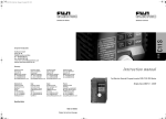
2.3 Specification Label
Name
Inverter Model
Adaptive Motor Power
Input Power Rating
Output Power Rating
INVERTER
MODEL : ZVF200-M0015T4MDR
POWER : 1.5KW
INPUT
: 3PH 380VAC 50/60Hz
OUTPUT : 3PH 4.0A 0-400Hz
Figure 2-2 Inverter Specifications Label
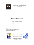
2.4 Outside Drawing & Structure
1. Upper Cover
2. Bottom Cover
3. Digital Keypad
4. Upper Shell
7. Power Terminal
5. Lower Shell
8. Fan
6. Input Output Terminal
Figure 2-4 Model A Structural Representation
2.5 Models and Specifications
Table 2-1 Inverter Models and Specifications
Figure 2-3 Model A Outside Drawing
-10-
Inverter Models
(ZVF200-M)
Input Voltage
(V)
Rated output
current (A)
ZVF200-M0004T2/S2
220
2.5
0.4
ZVF200-M0007T2/S2
220
5.0
0.75
ZVF200-M0015T2/S2
220
7.0
1.5
ZVF200-M0022T2/S2
220
10.0
2.2
ZVF200-M0037T2
220
17.0
3.7
-11-
Adaptive Motor
Power (KW)
Chapter 2 Introduction to the Product
Rated output
current (A)
Adaptive Motor
Power (KW)
ZVF200-M0055T2
220
25.0
5.5
ZVF200-M0007T4
380
3.0
0.75
ZVF200-M0015T4
380
4.0
1.5
ZVF200-M0022T4
380
5.0
2.2
ZVF200-M0037T4
380
8.5
3.7
ZVF200-M0055T4
380
13
5.5
ZVF200-M0075T4
380
18
7.5
2.6 Technical Indication
Item Description
Item
Input
Output
Control
Function
Rated voltage
frequency
Single phase/Three phase 220VAC . Three phase
380V.50HZ/60HZ
Allowable Voltage
range
Voltage fluctuate range: 220V:180V~264V ;380V:342~528V.
Voltage unbalance rate:<3%. Frequency fluctuation:
5%
Rated voltage
0~ three phase input AC voltage
Frequency
0.1~400HZ.
Modulation mode
SPWM (sinusoidal Pulse Width modulation)
Control mode
V/F control & sensorless vector control
Frequency
resolution
Digital setting :0.1HZ. Analog setting :Max.
Frequency x0.1%.
Overload capacity
150% of rated current for 1 minute
Torque
Characteristic
Including the auto-torque .Auto-slip compensation .
Start torque can be 150% at 5.0HZ.
Acel/Decel Time
0.1~600 seconds ( 2 independment setting for
Accel/Decel time )
-12-
Item Description
Item
Operation Function
Input Voltage
(V)
Control Function
Inverter Models
(ZVF200-M)
Chapter 2 Introduction to the Product
V/F pattern
Adjustable V/F Pattern
DC Breaking
Operation frequency 0~50HZ . Output 0~100 %
rated current .
Starting time 0~5 seconds . Stop time 0-25 seconds
Carrier frequency
1.0~15.0KHZ
Stall prevention level 20%~200% setting of rated current of inverter
Frequency setting
according to the motor load characteristic
Command
Keypad .External terminal control . COM Serial control
Frequency setting
Keypad potentiometer setting . Operation panel
setting . external Terminal UP/DOWN setting .
Analog signal setting . 485 COM Setting .
Multi-function
analog output
0-10VDC singal . Output frequency . current .output .
Output signal
Programmable relay . open collector output . Fault
signal output .
Other Function
AVR .Over voltage . Over-current stall prevention .
3-Groups fault records . Reverse inhibition .
Momentary Power loss restart . DC braking .
Auto torque& slip compensation . acceleration/
deceleration. S- curve .auto tuning . adjustable
carrier frequency. Frequency limits . Parameter lock
/reset. Vector control . PID control . Counter .remote
control .MODBUS communication . Abnormal reset ,
Abnormal restart . energy saving running . sleep/
revival function . 1st/2nd frequency source selection .
LED Display
Optional parts selection
can show the inverter running status. monitor
parameters. function parameters .error and ect.
braking assembly,remote keypad and connection
cable and soon.
-13-
Chapter 3 Installation and Wiring
Chapter 2 Introduction to the Product
Item
Item Description
Protection Function
Over Current .Over current .Under voltage .external
fault .Overload. Ground fault. Overheating .
Ambient
Installation location
Altitude 1000m or less .Keep from corrosive gas .
liquid and dust
Ambient Temperature -10
to 40
( -10
to 50
without blind plate )
Ambient
Structure
Ambient Humidity
Below 90% RH (no-condensing ).
Vibration
<0.5G
Storage temperature
-20
Protection Level
IP20
Cooling mode
Forced air cooling
Installation
Wall mounted
to 60
Chapter 3 Installation and Wiring
3.1 Installation
3.1.1 Use the inverter in the following environmental conditions:
Altitude: Maximum 1000m above sea level
Ambient Temperature: -10~+45 [Bare Machine: -10~+50 ]
Humidity: 20~90% RH (Non-condensing)
Ambient: Indoor places free from direct exposure to sunlight, dust,
corrosive gas, flammable gas, oil mist, steam, drip and salt
Vibration: < 0.5G
3.1.2 Installation Space and Direction
To get better cooling effect and convenience of maintenance, the
inverter shall be installed vertically with enough space left (refer to the
figure 3-1). When two and two more inverters are fixed in the same cabinet,
it is recommended to fix them in parallel and horizontally to reduce heat
produced by them (refer to the figure 3-2).When there is a must to fix them
vertically, please fix an insulating board between them so that the heat
produced by the lower one could not have direct influence on the upper
one (refer to the figure 3-3)
Figure 3-1 Installation
Space
-14-
Figure 3-2 Multi-piece
Parallel Installation
-15-
Figure 3-3 Multi-piece
Vertical Installation
Chapter 3 Installation and Wiring
3.2 Remote control keypads and wiring connection
STEP 1.Hand on the notch of the two sides( right and left) of the keypad and
pull it up by inward,remove the keypad.(as shown in the figure 3-4).
Chapter 3 Installation and Wiring
STEP 3.Insert the optional cable with the grounding side into the slot of
interface board. (as shown in the figure 3-6).
Fig. 3-6
Fig. 3-4
STPE 2.Install the optional interface board at the position of keypad.(as
shown in the figure 3-5).
STEP 4.Put the dismantled keypad into the installation frame . Fix and
fasten it . Put the other side cable insert into the keypad .(as shown in the
figure 3-7).
Fig. 3-5
Fig. 3-7
-16-
-17-
Chapter 3 Installation and Wiring
3.3 Wiring Diagram
Chapter 3 Installation and Wiring
3.2.2 Cautions for Wiring
3.3.1 Basic Wiring Diagram
Braking Resistor
P
DB
HAZARD
MOCB
R
S
T
Three phase
AC inpul
Power supply
Forward/Stop
Reverse/Stop
Reset
Multi-stage speed 1
Multi-stage speed 2
Multi-stage speed 3
Public Terminal
R
W
X1
X2
X3
X4
X5
X6
GND
Potentiometer
Input or analog
Voltage Input
(0 10VDC)
Analog Current
Input (0-20mA)
485 COM Port
M
V
Wait at least 10 minutes after power OFF before opening
the front cover of the inverter.
Verify the charge indicator lamp is OFF before proceeding
the work, and be sure that the voltage value of the main
loop terminal P and DC- is less than 36VDC.
The internal wiring of the inverter should be operated
only by authorized qualified people.
Fault Reley Output
TA
TB
TC
TA-TB on when normal
TA-TC on when failure
Y1
Open collector
Output
12V
10V
AFM
GND
AVI
V
Analog Signal Output
(0-10VDC)
AC1
GND
12V
COM
SG+
SG-
12V Power supply
output Port
WARNING
Fig.3-8
Model : ZVF200-M0004S2 M0022S2
ZVF200-M0004T2 M0055T2
ZVF200-M0007T4 M0075T4
-18-
Verify the rated input voltage of the inverter is matched
with AC power supply. Otherwise, there is the possibility
of damage to the inverter.
Install in order and only operate wiring after finishing
main parts install ation. Otherwise, there is an electric
shock or damage to the inverter.
Do not perform over-voltage withstand to the inverter,
for this had been done properly before EX-factory.
Be sure to install a no-fuse circui t breake r in the i nput
power supply side of the inverter to prevent expanding
of accident due to an inverter problem, which may cause
damage to the distribution equipment or lead to fire.
Be sure to connect the ground terminal and the motor
casing to the ground wire which must be copper core. The
diameter of the copper core should conform to the relevant
national standard. The ground resistanc e should be less
than 10 .
-19-
Chapter 3 Installation and Wiring
Chapter 3 Installation and Wiring
3.3.3 Instruction on Main Circuit Terminals
TIP
When the open-ended output terminal of the collector
connects to any inductive load, i.e., the relay coil, do
insert a diode at each end of the load in parallel.
The control wire in the inverter or the control cabinet
should be at least 100mm away from the power cable.
DO NOT put them in the same metallic channel. If t he
signal wire and the power cable need to intersect, they
should intersect at an angle of 90 . The control wire
must adopt STP (shielded twisted pair wire); the shielded
layer must connect to the terminal GND; and the power
wire is recommended to use metallic shielded cable.
1 The main circuit terminals are shown as in the figure 3-9~3-10.
Earthing
TIP
TIP
The unavoidable strong electromagnetic interference of
the inverter may have bad influence on all the electrical
equipment and meters in the same environment. To reduce
interference, the output cable of the inverter can be
inserted in the metal pipe connecting to the ground or in
the metallic shielded cable, and connect the metallic
shielded layer to the ground. In addition, a magnetic loop
put on the output cable is also effective to reduce
interference.
Input power RST disorder ,it can connect any one arbitrary
When inverter runs the direction of motor is not same as
your required direction. Please change any two of three
iuput motor wires
When inverter have disconnector to protect current leakage.
In order to avoid something wrong with disconnect ,please
choose current leakage above 200mA and fi nish it
within more than 0.1 second
-20-
Single phase
220V input
Connect with
three-phase AC motor
Connect with the
braking resistor
Fig.3-9 Diagram 1 for Main Circuit Terminals
Model: ZVF200-M0004S2 M0022S2
Earthing
Three-phase
220V/380V Input
Connect with
three-phase AC motor
Connect with the
braking resistor
Fig.3-10 Diagram 2 for Main Circuit Terminals
Model ZVF200-M0004T2
ZVF200-M0007T4
-21-
M0055T2
M0075T4
Chapter 3 Installation and Wiring
2 Function Description on Main Circuit Terminals
Terminal Symbols
R
S
U
P
V
W
Type
AC line input terminals, connecting with threephase 380V or 220V AC input
AC line input terminals, connecting with singlephase 220V AC input
N
2. Description of the control circuit terminal
Inverter output terminals connecting with
three-phase AC motor
Ground terminal connecting to the ground
Electrical Specifications
X2
X3
X4
X5
Xn (n=1, 2, 3, 6)-GND is
Valid only when there is a
short circuit The functions
can be set by the parameter
P38 P42
INPUT, 0~12V power level
low level valid, 10mA
Multi-function open collector
output is defined as on-off
output terminal, whose function
is set by the parameter P45
with reference of GND
OUTPUT, Maximum
Current Load I 50mA
X6
Y1
Public
port
G
Function Description
Multi-function
Output Terminal
DB
External braking resistor terminals, connecting with
two side of the external braking resistor
Terminal
Symbols
X1
Multi-function
Input Terminal
L
T
Function Description
Chapter 3 Installation and Wiring
GND
Analog signal public
terminal
+10V
External analog preset power
supply, connecting to
potentiometer together with
termianl GND and AVI.The
frequency can be set as
required
Output,10VDC
AVI
Analog voltage singal input,
with reference of GND
Input .0 10VDC
ACI
Analog current Singal input,
with reference of GND
Input .0 20mA
AFM
Program mable Analog voltage
output P43 with reference of
GND
Output .0 10VDC
3.2.4 Description of terminal of the control circuit
1.The terminal of control circuit shown in Fig 3-11.
-22-
Analog Input Output terminal
Fig 3-7 Control circuit terminal
-23-
Chapter 3 Installation and Wiring
Type
Chapter 3 Installation and Wiring
3.4 Inverter System Wiring
Terminal
Symbols
Function Description
Electrical Specifications
Power Programmable COMMUNICATION
port output terminal
PORT
Power Supply
12V
TA
TB
TC
12VDC output(control
power)
12VDC
100mA
Relay contact output.
Contact rated value
when normal TA and TB ON,
NO 250VAC-5A
TA-TC off. Action TA and
NO 250VAC-3A
TB off,TA-TC ON.Set by P46
SG+
Communication singal
positive port
SG-
Communication singal
negative port
No-Fuse
breaker
Magnetic
contactor
AC Input
Reactor
Capacity of break switch and section area of wire
Input Filter
2
Inverter Models
Main Circuit mm
Break
Control
Switch (A) Input Wire Output wire Wire (mm2)
ZVF200-M0004T2/S2
5/15
2.5
0.75
ZVF200-M0007T2/S2
10/20
2.5
0.75
ZVF200-M0015T2/S2
20/30
2.5
0.75
ZVF200-M0022T2/S2
30/50
4
0.75
ZVF200-M0037T2
40
6
0.75
ZVF200-M0055T2
50
6
0.75
ZVF200-M0007T4
5
2.5
0.75
ZVF200-M0015T4
10
2.5
0.75
ZVF200-M0022T4
15
2.5
0.75
ZVF200-M0037T4
20
4
0.75
ZVF200-M0055T4
30
4
0.75
ZVF200-M0075T4
40
6
0.75
-24-
Inverter
Output filter
Three phase
motor
Power Supply
Please follow the specific power supply requirem ent
shown in . Avoid the inverter damage .
Be sure to install No-Fuse breaker between the AC
power and inverter .
No-Fuse breaker
Make sure use the No-fuse that matched with the rated
voltage and current of the inverter for ON/OFF control.
and for the inverter protection .
No-Fuse breakers can notused as START or STOP control .
Magnetic contactor
Please do not use a magnetic contactor as the I/O switch
of the inverter this will reduce the operating life cycle
of the AC inverter .
Please do not use the magnetic contactor as START
and STOP of the inverter .
AC Input Reactor
AC line reactor should be installed when the power
supply capacity is 500kVA.
Used to improve the input power factor, to reduce
harmonics and provide protection from AC line
disturbances. (Surge,switching spike, power flick, etc.)
Input Filter
There have inductive load beside the inverter . The input
filter should be installed .
Inverter
The AC input line connect with R.S.T or L.N . No phase
different .
The output connect with U.V.W . It only change any two
phase among the three phases if the inverter run forward .
while the motor run reverse .
The output terminal can not connect with AC input line.
Avoid the inverter damage .
Good connection with earth ground .
Output filter
It's necessary to install on the inverter output side when
the inverter interfered by the sensitive equipment .and
can reduce the electromagnetic interference.
Fig.3-12
-25-
Chapter 4 Operation panel and Operation
Chapter 4 Operation panel and Operation
4.1 Operation Panel and Description
LED display
display frequency,
current, parameters,
error and etc.
LED Indicates
Lamp lights during RUN,
STOP,FWD & REV
operation.
RUN Key
ENTER/STORE Key
4.1.2 Function Description on Keys
Run Key. When the run command selected bey the keypad control
(P01=00).Press this key and the inverter start running .
4.1.1 Operation Panel
MODE Key
program/function mode
Chapter 4 Operation panel and Operation
STOP/RESET Key
STOP/RESET key. when the run command is selected by the keypad
control .(P01=00). The inverter is under normal running. Press th is key
to stop running.When the inverter is in the state of failure alarm.Press
this key remove the fault .and return to the normal status .
Program/Function mode key Press this key to displays the AC drive
status, setting fr equency .o utput curr en t . FW D/ RE V. pa ram ete rs
settings and so on.
UP and DOWN Key
Panel Potentiometer
E nte r/S tor e key. Press this key to confirm the current status of the inverter
or save the current parameter value.
Fig.4-1 ZR06 Operation Panel Description
Model: ZVF200-M0004S2 M0022S2
ZVF200-M0004T2 M0055T2
ZVF200-M0007T4 M0075T4
-26-
Up key. Press this key, the data or parameter code will go up. Press and
hold it, the modifying speed upward will rise.
Down key. Press this key, the data or parameter code will go down. Press
and hold it, the modifying speed downward will rise.
-27-
Chapter 4 Operation panel and Operation
4.1.3 Function Description on Operation Panel Indicator Lights
Display Status
Chapter 4 Operation panel and Operation
4.1.4 Use of Operation panel
State parameter view
Function Description
The AC drives master frequency.
Initializing
The actual running frequency
The customer unit(V)
The output current preset at terminal U V
W
Run program automatic
Parameter item
Parameter value
Modification of parameter value (modify the parameter value for P16
jog function from 6.00Hz to 10.00Hz).
the inverter is in the state of forward running.
Initializing
the inverter is in the state of reverse running
"End" displays for approximately 1 second if input has been
accepted. After a parameter value has been set, the new
value is automatically stored in memory. To modify an
entry, use the
and
keys.
"Err" displays, if the input is invalid.
RUN
STOP
When the light is ON,inveter is running
When the light is ON,inverter will stop
FWD
When the light is ON, the inverter is in the state of forward
running
REV
When the light is ON, the inverter is in the state of reverse
running.
-28-
Data fault
Data right
For a second
-29-
Chapter 5 Inverter Use
Chapter 4 Operation panel and Operation
When running mode is controlled by keypads, revise the methods of
running direction
Chapter 5 Inverter Use
5.1 Trial Operation
Initializing
5.1.1 Safety Instruction on Trial Operation
Press two times
When frequency is set by key up and down
Initializing
Parameter initializing (restore to the factory default setting 50.00Hz)
Initializing
The following steps should be inspected and confirmed before the trial
operation of the inverter:
Be sure the application ambient and installation for the inverter is in
accordance with the requirements specified in Clause 3.1.
Be sure the main circuit is correctly wired. The input power supply of
the inverter must be connected to the terminal R, S and T or L,N. The
output terminal U, V and W must be connected to the motor.
Be sure the ground terminal is good grounded.
Be sure all the switches and terminals are in proper state of off or
shut down.
Be sure there is no short circuit or short to ground of all the terminals
and electrified parts.
Be sure all the terminals, connectors and screws are tightly fastened.
Be sure the motor has no other loads.
5.1.2 Trial Operation
Try this step only after careful inspection as mentioned in the clause
5.1.2. While in trial operation, it is suggested that the motor without
load to avoid damage to this mechanical equipment arising from incorrect
operation. During trial operation, if the operating instruction is P01,
then the RUN/STOP key control (factory default setting) of the operation
panel must be selected. The trial operation steps must be followed as
shown in the table 5-1 below.
Data right
For a second
-30-
-31-
Chapter 5 Inverter Use
Table 5-1 Trial Operation Steps
Order
1
Operation
Switch on, inverter
energized.
Description
After energized, the inverter is in the state
of readiness and LED displays F50.00Hz.
the built-in cooling fan begin to work.
2
Press / till LED
displays F5.00Hz.
Set the frequency to F5.00Hz. This step can
be left out if the displayed frequency is
already F5.00Hz when energized.
3
Press RUN .
Motor begins running, the frequency
rise from H0.00Hz to H5.00Hz, under the
frequency monitor
4
Keep a close eye on the
following points:
if there is any abnormal
vibration or noise when the
motor runs.
if there is any tripping or
other abnormality of the
inverter.
If the motor runs in the
correct direction.
if the value for rotation
speed and frequency iscorrect.
If there is any anomaly or tripping, stop
running immediately and cut off the power
supply.
Please refer to Chapter 7, find the trouble
causes, then proceed trial operation again
after troubleshooting.
If the motor runs in the wrong direction,
change arbitrary two-phase connection of
the output terminal U, V or W.
Go to the next step if everything is normal.
5
Press
continuously till
LED displays F50.00Hz.
The motor accelerates rotating and the
displayed frequency rises from H5.00Hz to
H50.00Hz. Go to the next step if everything
is normal.
6
Press
continuously till
LED displays F0.00Hz.
The motor decelerates rotating and the
displayed frequency falls from H50.00Hz to
H0.00 Hz. Go to the next step if everything
is normal.
7
Press STOP .
The inverter stops outputting, the motor
stops running and the trial operation ends.
If everything is normal, please repeat the
operation for several times.
-32-
Chapter 5 Inverter Use
5.1.3 Cautions for Operation
All the inverter functions are determined by set parameters. The
parameters of inverter ZVF200 series consist of the function codes
P00~P157, see the detail in Chapter 6 of this manual. The displayed
parameter value of each function code is the factory default value of the
inverter before EX factory, which can be modified by the user according
to his needs. It is noteworthy that a user shall change the relative function
parameters when he amends a parameter because some of the parameters
are inter-related . It is not recommended to modify the set parameter value
if there is no special requirement, for the factory default setting has been
done properly. Otherwise, this may cause damage to the inverter or
equipment due to error parameter.
In case there is an error alternation of the parameter, please initialize
the parameter with reference to the operation method in the clause 4.1.4
Parameter Initializing Restoring Factory Default Settings .
-33-
Chapter 5 Inverter Use
5.2 Examples of Use
This manual provides the following examples for users' reference on
the use of inverter.
5.2.1 Eg. 1: Run or stop the inverter with operation panel, and feed the
frequency with panel potentiometer .
Chapter 5 Inverter Use
5.2.2 Eg.2: Start and stop the inverter with the external terminal ,
feed the frequency with external potentiometer .
MCCB
Three-phase
AC Power
Supply
R
S
T
U
V
W
G
MCCB
Three-phase
AC Power
Supply
R
S
T
U
V
W
G
M
TA
Relay Failure
TB Output
TC
Forward
Reverse
Reset
4.7-10K/2W
FWD
REV
X1
COM
+10V
AVI
GND
M
TA
Relay Failure
TB Output
TC
GND
AFM
V
Voltage Output
Fig. 5-2
GND
AFM
V
Voltage Output
Fig.5-1
P00-Master frequency source selection .
If the set value 04 Panel Potentiometer setting .
P01-Source of operation command .
If the value is 0 keypad control
Run or stop the inverter with
or
keys on the operation panel.
Adjust the speed by turning the potentiometer on the operate panel .
-34-
P00-Master frequency source selection .
The set value 01 is external voltage or external potentiometer value .
P01-Source of operation command .
If the value is 01- External terminal control .
P38- The input terminal X1.2 function selection .
The value 00-Two Wire running control
P39-Input terminal X3 function selection . 05-External reset input .
X1-GND switch on . The motor run forward .
X2-GND switch on . The motor run reverse .
X1 X2-GND both switch on or switch off at the same time .The inverter
will stop .The fault alert X3-GND switch on . the fault reset .
The speed control by the regulating value of AVI .(controlled by
4.7-10K/2W potentiometer control .)
-35-
Chapter 5 Inverter Use
Chapter 5 Inverter Use
5.2.3 Eg.3: Run or stop the inverter with external terminal.Multi-stage speed
running.
5.2.4 Eg.4: Run and stop the inverter with the external terminal , feed the
frequency with external potentiometer . Multiple motors run
in parallel .
MCCB
Three-phase
AC Power
Supply
Forward
Reverse
R
S
T
U
V
W
G
TA
Relay Failure
TB Output
TC
X1
X2
Three-phase
AC Power
Supply
Forward
Reverse
Reset
X3
X4
X5
GND
AFM
4.7-10K/2W
V
Voltage Output
Fig. 5-3
P01-Source of operation command. If the value is 01- External terminal
control .
P38-The input terminal X1.2 function selection .
The value 00-Two Wire running control.
P39-P41 The input terminal X3-X5 function selection. The setting
value 06,07,08 Multi stage speed .
P17-P23-Multi-stage speed frequency setting . There have 7 stages
frequency . and use the factory fault .
X1-GND switch on . The motor run forward .
X2-GND switch on . The motor run reverse .
X1 X2-GND both switch on or switch off at the same time .The inverter
will stop .
There have an arbitrary terminal or Multi terminals and GND switch
off (7 Pairs of such complex in total ),The inverter will run under the
multi-stage speed frequency selected from X3-X5.
-36-
R
S
T
U
V
W
G
M
M
FWD
REV
X1
COM
+10V
AVI
GND
GND
Multistage
Speed Control
Terminal
Electronic thermal relay
MCCB
M
TA
Relay Failure
TB
Output
TC
M
GND
AFM
V
Voltage Output
Fig. 5-4
P00-Master frequency source selection . The set value 01 is external
voltage or external potentiometer value .
P01-Source of operation command. If the value is 01- External terminal
control .
P38- The input terminal X1.2 function selection .
The value 00-Two Wire running control
P39-Input terminal X3 function selection . 05-External reset input .
X1-GND switch on . The motor run forward .
X2-GND switch on . The motor run reverse .
X1 X2-GND both switch on or switch off at the same time .The inverter
will stop .
The fault alert X3-GND switch on . the fault reset .
The speed control by the regulating value of AVI .(controlled by
4.7-10K/2W potentiometer control .)
Each motor will use the thermal relay to do overload protection . The
total power of all motors are less than the rated power of inverter .
-37-
Chapter 5 Inverter Use
5.2.5 Eg.5: Inverter use for PID control Pressure Water supply control.
working
frequency
running
Three-phase
AC Power
Supply
variable frequency running
Forward
Relay Failure
Output
Reset
Feed (feedback) signal
Feedback (feed) signal
Voltage Output
Fig. 5-5
P01-Source of operation command . If the value is 01- External terminal
control .
P38- The input terminal X1.2 function selection .
The value 00-Two Wire running control
P39-Input terminal X3 function selection . 05-External reset input .
P115-PID set point selection . If we set 02-Select the external voltage
or potentiometer setting .
P116-PID Feedback terminal selection . The setting value 03 Select
external current negative feedback .
P117-Proportional gain P: Set according to the actual request . No
need to change .
-38-
Chapter 5 Inverter Use
P118- Integral time I : Set according to the actual request . No need to
change .
P119- Differential time D: Set according to the actual request . No need
to change .
P131- Minimum frequency corresponding to the ACI input current
value. No need to change .
P132- Maximum frequency corresponding to the ACI input current
value. No need to change .
P133-The reverse ACI . Set according to the actual request . No need
to change .
P136-The sleep time : Set according to the actual request . No need to
change .
P137-The sleep frequency : Set according to the actual request . No
need to change .
P138- The wake up frequency.Set according to the actual request. No
need to change .
When use the PID function. In order to meet the control demands. Customers
can modify the parameter according to the actual request .
WARNING
The contactor KM1, KM2 are shifting from working
frequency and variable frequency.Must be designed in
interlocked manner.
It is forbidden to close at the same time. Otherwise the
inverter will be permanent damaged .
-39-
Chapter 6 Parameters
Chapter 6 Parameters
Chapter 6 Parameters
6.1.1 Basic Operation Functions
Parameter
Explanation
Settings
6.1 Schedule of Function Parameters
The mark "
" indicates the setting value of parameter can
be modified no matter when the inverter is shutdown or
running.
The mark " " indicates the setting value of parameter can
TIP
be modified only when the inverter is shutdown, and can
P00
not be modified when the inverter is running.
Source of
Frequency
Command
The mark "_" indicates the parameter can be displayed only
and can not be modified.
-40-
00: Master frequency determined
by operation panel ( / )
01: Master frequency determined
by 0 to +10 V input on AVI
terminal with jumpers
02: Master frequency determined
by 4 to 20mA input on ACI
terminal with jumpers
03: Master frequency determined
by RS-485 Communication
port
04: Master frequency determined
by potentiometer on operation
panel
P01
Source of
Operation
command
00: Operation determined by
operation panel RUN / STOP
01: Operation determined by
external control terminals,
keypad STOP is effective
02: Operation determined by
external control terminals,
keypad STOP is ineffective
03: Operation determined by
RS-485 communication
port, keypad STOP is effective
04: Operation determined by
RS-485 communication
port, keypad STOP is
ineffective
P02
Stop Method
00: Ramp stop
01: Coast Stop
-41-
Unit
Min. Default Factory
Unit Setting Setting
1
00
1
00
1
00
Chapter 6 Parameters
Parameter
Explanation
P03
Maximum Output
Frequency
P04
Maximum Voltage
Frequency (Base
Frequency)
Settings
50.00 to 400.0 Hz
10.00 to 400.0Hz
Unit
Hz
Hz
Min. Default Factory
Unit Setting Setting
0.1 50.00Hz
P05
V
P06
Mid-point
Frequency
0.10 to 400.0Hz
Hz
0.1 1.50Hz
P07
Mid-point
Voltage
220V: 0.1 to 255.0V
380V: 0.1 to 510.0V
V
0.1
P08
Minimum Output
Frequency
0.10 to 20.00Hz
Hz
0.1 1.50Hz
P09
Minimum Output
Voltage
220V: 0.1 to 255.0V
380V: 0.1 to 510.0V
V
0.1
10.0V
20.0V
P10
Acceleration
Time 1
s
0.1
10.0s
P11
Deceleration
Time 1
s
0.1
10.0s
P12
Acceleration
Time 2
P13
Deceleration
Time 2
0.01 to 600.0 sec
Note:The decimal digits are
determined by P147
P14
Accel S-curve
00 to 07
0.01 to 600.0 sec
P15
Jog Accel/Decel
Time
Note:The decimal digits are
determined by P147
-42-
1
220.0V
440.0V
10.0V
20.0V
s
0.1
10.0s
s
0.1
10.0s
1
00
0.1
1.0s
s
Parameter
Explanation
Settings
Unit
Min. Default Factory
Unit Setting Setting
P16
Jog Frequency
0.00 to 400.0 Hz
Hz
0.1 6.00Hz
P17
1st Step Speed
Freq.
0.00 to 400.0 Hz
Hz
0.1 0.00Hz
P18
2nd Step Speed
Freq.
0.00 to 400.0 Hz
Hz
0.1 0.00Hz
P19
3rd Step Speed
Freq.
0.00 to 400.0 Hz
Hz
0.1 0.00Hz
P20
4th Step Speed
Freq.
0.00 to 400.0 Hz
Hz
0.1 0.00Hz
P21
5th Step Speed
Freq.
0.00 to 400.0 Hz
Hz
0.1 0.00Hz
P22
6th Step Speed
Freq.
0.00 to 400.0 Hz
Hz
0.1 0.00Hz
P23
7th Step Speed
Freq.
0.00 to 400.0 Hz
Hz
0.1 0.00Hz
P24
Reverse Operation
Inhibition
00: Enable REV operation
01: Disable REV operation
P25
Over-Voltage
Stall Prevention
00: Disable
220V: 330 to 450 V
380V: 660 to 900 Vdc
P26
Over-current Stall
Prevention during
Acceleration
Over-current Stall
P27 Prevention during
Operation
0.1 50.00Hz
Maximum Output 220V: 0.1 to 255.0V
Voltage (Vmax)
380V: 0.1 to 510.0V
0.01 to 600.0 sec
Note:The decimal digits are
determined by P147
Chapter 6 Parameters
1
00
V
0.1
390.0V
780.0V
00: Disable
20% to 200%
%
1
150%
00: Disable
20% to 200%
%
1
150%
-43-
Chapter 6 Parameters
Parameter
Explanation
Settings
Unit
Min. Default Factory
Unit Setting Setting
Parameter
P37
Lower Bound of
0.00 Hz to 400.0Hz
Output Frequency
P38
Multi-function
Input
Terminal
(X1,X2)
P28
DC Braking
Current Level
00 to 100 %
%
1
00%
P29
DC Braking
during Start-up
0.0 to 5.0 sec
s
0.1
0.0s
P30
DC Braking
during Stopping
0.0 to 25.0 sec
s
0.1
0.0s
P31
Start-point for
DC Braking
0.00 to 60.00 Hz
P32
Momentary
Power Loss
Operation
Selection
00: Stop operation after
momentary power loss
01: Continues after momentary
power loss, speed search
starts with Master Frequency
02: Continues after momentary
power loss, speed search
starts with Minimum output
Frequency
P33
Maximum
Allowable
Power Loss Time
0.3 to 5.0 sec
P34
Base-Block Time
for Speed Search
0.3 to 5.0 sec
P35
P36
Hz
00
s
0.1
2.0s
s
0.1
0.5s
Maximum Current
30 to 200%
Level for Speed
Search
%
1
150%
Upper Bound of
Output Frequency
Hz
-44-
Explanation
0.1 0.00Hz
1
0.10 Hz to 400.0Hz
Chapter 6 Parameters
0.1 400.0Hz
P39
Multi-function
Input
Terminal (X3)
P40
Multi-function
Input
Terminal (X4)
P41
Multi-function
Input
Terminal (X5)
Settings
00: X1: FWD/STOP,
X2: REV/STOP
01: X1: RUN/STOP,
X2: REV/FWD
02: X1, X2, X3: 3-wire
operation control mode
00: No Function
01: Output OFF (NC) (enabled
when running)
02: Output OFF (NO) (enabled
when running)
03: External Fault (normally
open) (NO)
04: External Fault (normally
close) (NC)
05: RESET
06: Multi-Step Speed
Command 1
07: Multi-Step Speed
Command 2
08: Multi-Step Speed
Command 3
09: Jog Operation
10: Accel/Decel Speed Inhibit
11: First or Second Accel/Decel
Time
12: Base-block (B.B.) (NO)
13: Base-block (B.B.) (NC)
14: Increase Master Frequency
15: Decrease Master Frequency
16: Run PLC Program
17: Pause PLC
18: Counter Trigger Signal
19: Counter Reset
20: No function
-45-
Unit
Hz
Min. Default Factory
Unit Setting Setting
0.1 0.00Hz
1
00
1
05
1
06
1
07
Chapter 6 Parameters
Parameter
P42
P43
P44
P45
Explanation
Settings
Unit
Min. Default Factory
Unit Setting Setting
Multi-function
Input
Terminal (X6)
21: RESET command (NC)
22: Control source: External
Terminal
23: Control source: Keypad
24: Control source:
Communication
25: Parameter Lock (Write
disable, Read is always 0)
26: PID Disable (NO.)
Hz
27: PID Disable (NC)
28: Second Source for Frequency
Command
29: Forward (contact is open) /
Reverse (contact is close)
30: One-Shot PLC Run
31: Index input signal
32: Counter Incremented by
Drive Output Frequency
1
Analog Output
Signal AFM
00: Output frequency
01: Output current
02: PID feedback signal
03: Output power
1
Analog Output
Gain AFM
00 to 200 %
Multi-Function
Output
Terminal Y1
(Photocoupler
output)
00: AC Drive Operational
01: Maximum Output
Frequency Attained
02: Zero Speed
03: Over-Torque Detection
04: Base -Block (B.B) Indication
05: Low Voltage Indication
-46-
%
Chapter 6 Parameters
Parameter
08
P46
1
1
00
Explanation
Settings
Programmable
relay function
selection
06: AC Drive Operation Mode
07: Fault Indication
08: Desired Frequency Attained
09: PLC Program Running
10: PLC Program Step Completed
11: PLC Program Completed
12: PLC Operation Paused
13: Top Count Value Attained
14: Preliminary Counter Value
Attained
15: Warning (PID feedback loss,
communication error)
16: Below the Desired Frequency
17: PID supervision
18: Over Voltage supervision
19: Over Heat supervision
20: Over Current stall supervision
21: Over Voltage stall supervision
22: Forward command
23: Reverse command
24: Zero Speed (Includes
Drive Stop)
Unit
Min. Default Factory
Unit Setting Setting
1
07
P47
Desired Frequency
0.00 to 400.0Hz
Attained
Hz
0.1 0.00Hz
P48
Adjust Bias of
External
0.00 to 100.0%
Input Frequency
%
0.1
0.0%
P49
Potentiometer
Bias Polarity
00: Positive Bias
01: Negative Bias
1
00
P50
Potentiometer
Frequency Gain
0.10 to 200.0%
P51
Potentiometer
Reverse Motion
Enable
00: Reverse Motion Disabled
in negative bias
01: Reverse Motion Enabled in
negative bias
100%
00
-47-
%
0.1 100.0%
1
00
Chapter 6 Parameters
Settings
Unit
Motor Rated
Current
30.0% 120.0% rated output
current
A
P53
Motor No-Load
Current
00%FLA to 99%FLA
A
P54
Torque
Compensation
00 to 10
P55
Slip
Compensation
0.00 to 10.00
P56
Reserved
P57
AC Drive Rated
Current Display
(unit: 0.1A)
P58
Electronic
Thermal
Overload Relay
P59
Electronic Thermal 30 to 300 sec
Motor Overload
Parameter
P52
P60
Explanation
Over-Torque
Detection Mode
Min. Default Factory
Unit Setting Setting
0.1
Chapter 6 Parameters
Parameter
Explanation
Settings
P60
Over-Torque
Detection Mode
03: Enabled during acceleration
until the allowable time for
detection elapses.
04: Enabled during acceleration
and halted after detection.
According
to request
0.1 0.4*P52
00: Over-Torque Detection
Disable
01: Enabled during constant
speed operation until the
allowable time for detection
elapses.
02: Enabled during constant
speed operation and halted
after detection.
-48-
s
Min. Default Factory
Unit Setting Setting
1
00
1
00
P61
Over-Torque
30 to 200%
Detection Level
%
1
150%
0.01
0.00
P62
Over-Torque
Detection Time
0.0 to 10.0 seconds
s
1
0.1s
Loss of ACI
00: Decelerate to 0 Hz
01: Stop immediately and
display "EF"
02: Continue operation by last
frequency command
1
00
P64
User Defined
Function
for Display
00: Display AC drive output
Frequency (Hz)
01: Display User-defined output
Frequency (H*P65)
02: Output Voltage (E)
03: DC Bus Voltage (u)
04: PV (i)
05: Display the value of internal
counter (c)
06: Display the setting frequency
(F )
07: Display the parameter setting
(P)
08: Reserved
09: Output Current (A)
10: Display program operation
(0.xxx), Fwd, or Rev
1
06
P65
Coefficient K
0.01 to 160.0
0.01
1.00
P63
00: Standard Motor (self cool
motor)
01: Inverter Motor (auxiliary
cool fan on motor)
02: Inactive
Unit
1
02
1
60s
1
00
-49-
Chapter 6 Parameters
Settings
Min. Default Factory
Unit Setting Setting
Parameter
Explanation
P66
Communication
Frequency
0.00 to 400.0 Hz
Hz
0.1 0.00Hz
P67
Skip Frequency 1 0.00 to 400.0 Hz
Hz
0.1 0.00Hz
P68
Skip Frequency 2 0.00 to 400.0 Hz
Hz
0.1 0.00Hz
P69
Skip Frequency 3 0.00 to 400.0 Hz
Hz
0.1 0.00Hz
P70
Skip Frequency
Band
0.10 to 20.00 Hz
Hz
0.1 0.00Hz
P71
PWM Carrier
Frequency
01 to 15KHz
P72
Auto Restart
Attempts
after Fault
00 to 10
P73
P74
Present Fault
Record
Second Most
Recent
Fault Record
00: No fault occurred
01: Over-current (oc)
02: Over-voltage (ov)
03: Overheat (oH)
04: Overload (oL)
05: Overload 1 (oL1)
06: External Fault (EF)
07: CPU failure 1 (CF1)
08: CPU failure 2 (CF2)
09: Hardware Protection
Failure (HPF)
10: Over-current during
acceleration (oca)
11: Over-current during
deceleration (ocd)
-50-
Unit
KHz
1
15KHz
1
00
1
00
1
00
Chapter 6 Parameters
Parameter
Explanation
Settings
Unit
Min. Default Factory
Unit Setting Setting
Third Most
Recent
Fault Record
12: Over-current during steady
state operation (ocn)
13: Ground fault or fuse failure
(GFF)
14: Low Voltage (not record)
15: 3 Phase Input Power Loss
16: EPROM failure (CF3)
17: External interrupt allo
wance(bb)
18: Overload (oL2)
19: Auto Adjustable accel/decel
failure (CFA)
20: CPU self detection failure
(codE)
1
00
P76
Parameter Lock
and
Configuration
00: All parameters can be set/read
01: All parameters are read-only
02-08: Reserved
09: Resets all parameters to
50Hz factory defaults
10: Resets all parameters to
60Hz factory defaults
1
00
P77
Time for Auto
Reset the Restart
0.1 to 6000.0s
Times in
Abnormality
0.1
60.0s
1
00
P75
P78
PLC Operation
Mode
00: Disable PLC operation
01: Execute one program cycle
02: Continuously execute
program cycles
03: Execute one program cycle
step by step
04: Continuously execute one
program cycle step by step
-51-
s
Chapter 6 Parameters
Settings
Min. Default Factory
Unit Setting Setting
Parameter
Explanation
P79
PLC FWD/REV
Motion
P80
Reserved
P81
Time Duration of
00 to 9999 sec
1st Step Speed
s
1
00s
P82
Time Duration of
00 to 9999 sec
2nd Step Speed
s
1
00s
P83
Time Duration of
00 to 9999 sec
3rd Step Speed
s
1
00s
P84
Time Duration of
00 to 9999 sec
4th Step Speed
s
1
00s
P85
Time Duration of
00 to 9999 sec
5th Step Speed
s
1
00s
P86
Time Duration of
00 to 9999 sec
6th Step Speed
s
1
00s
00 to 127
1
P87
Time Duration of
00 to 9999 sec
7th Step Speed
P88
Communication
Address
01 to 254
Transmission
Speed
00: 4800 bps
01: 9600 bps
02: 19200 bps
03: 38400 bps
P89
Unit
-52-
s
00s
1
01
01
Min. Default Factory
Unit Setting Setting
Parameter
Explanation
Settings
P90
Transmission
Fault
Treatment /Stop
mode selection
00: Warn and Continue Operating
01: Warn and RAMP to Stop
02: Warn and COAST to Stop
03: Keep Operation without
Warning
P91
Time Out
Detection
0.0: Disable
0.1 to 120.0 sec
P92
Communication
data format
selection
00: MODBUS ASCII mode,
<7,N,2>
01: MODBUS ASCII mode,
<7,E,1>
02: MODBUS ASCII mode,
<7,O,1>
03: MODBUS RTU mode,
<8,N,2>
04: MODBUS RTU mode,
<8,E,1>
05: MODBUS RTU mode,
<8,O,1>
P93
Accel 1 to Accel 2
0.01 to 400.0Hz
Frequency
0.00: Disable
Transition
Hz
0.1 0.00Hz
P94
Decel 1 to Decel 2
0.01 to 400.0Hz
Frequency
0.00: Disable
Transition
Hz
0.1 0.00Hz
P95
Auto Energy
Saving
P96
P97
00
1
1
Chapter 6 Parameters
00: Disable auto energy saving
01: Enable auto energy saving
Unit
s
1
03
0.1
0.0s
1
00
1
00
Counter Countdown
00 to 9999
Complete
1
00
Preset counter
countdown
1
00
00 to 9999
-53-
Chapter 6 Parameters
Parameter
Settings
Explanation
Unit
Min. Default Factory
Unit Setting Setting
Chapter 6 Parameters
Parameter
Settings
Explanation
P98
Total Time
Count from
Power On (D)
Vector Slip
P108 Compensation
Filter
P99
Total Time
Count from
Power On (M)
Selection for Zero 00: No output
P109 Speed Control
01: Control by DC voltage
P100 Software Version
P101
Auto Adjustable
Accel/Decel
Auto Voltage
P102 Regulation
(AVR)
P103
Auto tune Motor
Parameters
00: Linear Accel/Decel
01: Auto Accel, Linear Decel
02: Linear Accel, Auto Decel
03: Auto Accel/Decel
04: Linear Accel/Decel Stall
Prevention during
Deceleration
1
00: Disable
01: Auto tune for R1
02: Auto tune for R1 + No
Load testing
1
00
1
00m
1
00
00 to 6553 m
P105 Control Mode
00: V/F Control
01: Vector Control
P107
Vector Voltage
Filter
00
00: AVR function enabled
01: AVR function disabled
02: AVR function disabled
when stops
03: AVR function disabled
when decel
P104 R1 value
P106 Rated Slip
1
0.00 to 10.00 Hz
5 to 9999
Hz
1
-54-
10
1
50
1
00
0.1
5.0%
0.0 to 20.0 %
P111 Decel S-curve
00 to 07
1
00
External Terminal
01 to 20
P112 Scanning Time
1
01
Restart Method
after Fault
00: None speed search
01: Continue operation after
fault speed search from
speed reference
02: Continue operation after
fault speed search from
Minimum speed
1
01
Cooling Fan
Control
00: Fan Off when the drive
stop after 1 Min.
01: AC Drive Runs and Fan
On, AC Drive Stops and
Fan Off
02: Always Run
03: Reserved
1
02
00: Disable ( No PID )
01: Keypad
02: AVI (external 0-10V)
03: ACI (external 4-20mA)
04: PID set point
1
00
00
0.1 3.00Hz
25 to 9999
Min. Default Factory
Unit Setting Setting
Voltage of Zero
P110 Speed Control
P113
m
Unit
P114
PID Set Point
P115
Selection
-55-
%
Chapter 6 Parameters
Parameter
Settings
Explanation
PID Feedback
P116 Terminal
Selection
Proportional
P117 Gain (P)
00: Input positive PID feedback,
PV from AVI (0 to 10V)
01: Input negative PID feedback,
PV from AVI (0 to 10V)
02: Input positive PID feedback,
PV from ACI (4 to 20mA)
03: Input negative PID feedback,
PV from ACI (4 to 20mA)
Min. Default Factory
Unit Setting Setting
1
0.0 to 10.0
P118 Integral Time (I) 0.01 to 100.0 sec
Differential
P119 Time (D)
Unit
s
00
0.1
1.0
0.01
1.00s
Chapter 6 Parameters
Settings
Min. Default Factory
Unit Setting Setting
Parameter
Explanation
P127
Detection Time
of PID Offset
0.1 to 300.0 sec
s
0.1
5.0s
P128
Minimum
Reference Value
0.0 to 10.0 V
V
0.1
0.0V
P129
Maximum
Reference Value
0.0 to 10.0 V
V
0.1
10.0V
P130
Invert Reference
Signal AVI
(0-10V)
00: Not inverted
01: Inverted
1
00
P131
Minimum
Reference
Value (4-20mA)
0.0 to 20.0mA
mA
0.1
4.0mA
0.0 to 20.0mA
mA
0.1 20.0mA
Unit
s
0.01
0.00s
Integration's Upper
P120 Bound Frequency 00 to 100 %
%
1
100%
P132
Maximum
Reference
Value (4-20mA)
PID One-Time
P121 Delay
s
0.1
0.0s
P133
Invert Reference 00: Not inverted
Signal (4-20mA) 01: Inverted
1
00
%
1
100%
P134
Analog Input
Delay Filter for
Set Point
00 to 9999
1
50
s
0.1
60.0s
P135
Analog Input
Delay Filter for
Feedback Signal
00 to 9999
1
5
P136
Sleep Period
0.0 to 6550.0 sec
s
0.1
0.0s
0.00 to 400.0 Hz
Hz
0.1 0.00Hz
0.00 to 400.0 Hz
Hz
0.1 0.00Hz
0.00 to 1.00 sec
0.0 to 2.5 sec
PID Frequency
00 to 110 %
P122 Output
Command Limit
P123
Feedback Signal 0.0: Disable
Detection Time 0.1 to 3600 sec
Feedback Signal 00: Warning and RAMP to stop
P124
Fault Treatment 01: Warning and keep operating
Source of PID
P125
Set Point
0.00 to 400.0Hz
P126 PID Offset Level 1.0 to 50.0 %
-56-
1
00
Hz
0.1 0.00Hz
P137
Sleep Frequency
%
10.0%
P138
Wake Up
Frequency
0.1
-57-
Chapter 6 Parameters
Parameter
Settings
Explanation
Unit
Min. Default Factory
Unit Setting Setting
Parameter
Explanation
P150
Index Angle for
Simple
Index Function
00.0 to 360.0
P151
Deceleration
Time for Simple
Index Function
0.00 to 100.00 sec
P152
Skip Frequency
Width
0.00 to 400.0Hz
Hz
0.1 0.00Hz
P153
Bias Frequency
Width
0.00 to 400.0Hz
Hz
0.1 0.00Hz
P154
Reserved
P155
Compensation
0.0: Disable
Coefficient for
Motor Instability 0.1 to 5.0
P156
Communication
Response Delay
Time
00
P157
Communication
Mode
Selection
Treatment for
P139 Counter
Attained
00: Continue operation
01: Stop Immediately and
display E.F
1
00
External
P140 Up/Down
Selection
00: Fixed Mode (keypad)
01: By Accel or Decel Time
1
00
00: Not Save
01: Save
1
01
Second Source
P142 of Frequency
Command
00: Keypad Up/Down
01: AVI (0-10V)
02: ACI (4-20mA)
03: Communication
04: Keypad potentiometer
1
Software
P143 Braking Level
220V: 370-450 V
380V: 450-900 Vdc
P141
Save Frequency
Set Point
V
00
380.0V
0.1
760.0V
Total operation
P144 time (Day)
Total operation
P145 time (Minutes)
P146
Line start
Lockout
00: Disable
01: Enable
1
Decimal Number
00: One decimal
P147 of Accel / Decel
01: Two decimals
Time
P148
Number of Motor
02 to 20
Poles
Gear Ratio for
P149 Simple
Index Function
04 1000
-58-
Chapter 6 Parameters
00
1
00
1
04
1
200
Settings
Unit
s
Min. Default Factory
Unit Setting Setting
0.1
180.0
0.1
0.00s
0.1
0.0
200
1
00
0: Reserved
1: Modbus
1
01
-59-
Chapter 6 Parameters
Chapter 6 Parameters
6.2 Description of Parameters Settings
P 00
Source of Frequency Command
Factory Setting
00 Master Frequency determined by digital keypad. (
00
/
)
01 Master frequency determined by 0 to +10 V input
Settings 02 Master frequency determined by 4 to 20mA input
03 Master frequency determined by RS-485 Communication port
04 Master frequency determined by potentiometer on digital keypad.
P 01
Source of Operation Command
Factory Setting
00
Fig.6-1
Operation instructions determined by the Digital Keypad.
00
( RUN/STOP )
01
Operation instructions determined by the External Control
Terminals. Keypad STOP key is effective.
Settings 02
Operation instructions determined by the External Control
Terminals. Keypad STOP key is not effective.
03
Operation instructions determined by the RS-485
communication port. Keypad STOP key is effective.
04
Operation instructions determined by the RS-485
communication port. Keypad STOP key is not effective.
TIP
P 03
Refer to P38 to P42 for more details.
P 02
Source of Operation Command
Settings
Factory Setting
01 Coast to stop
This parameter determines how the motor is stopped when the AC drive
receives a valid stop command. As shown in Fig6-1.
00 Ramp: The AC drive decelerates the motor to Minimum Output Freq uency
(P08) and then stops according to the deceleration time set in
P11 or P13.
01 Coast: The AC drive will stop the output instantly, and the motor will
coast to stop.
-60-
Maximum Output Frequency
Factory Setting 50.00
Settings 50.00 to 400.0 Hz
00
00 Ramp to stop
The mode for motor stop. Usually determined by the
characteristics of load or mechanical stops.
1. Mechanical stop. The motor must stop immediately.
Avoid material waste or people safety .It is recommende d
to set ramp stop. The deceleration time determined by
the actual sites.
2. Mechanical stop. It is recommended to set coast stop
If the motor run without load or the load with big inertia.
E.g. Fan . Mixer .
This parameter determines the AC drive's Maximum Output Frequency.
All the AC drive analog inputs (0 to +10V, 4 to 20mA) are scaled to
correspond to the output frequency range.
P 04
Maximum Voltage Frequency (Base Frequency) Factory Setting 50.00
Settings 10.00 to 400.0Hz
This parameter should be set according to the rated frequency as indicated
in the motor nameplate. P04 and P03 determine the volts per hertz ratio.
-61-
Chapter 6 Parameters
P 05
Maximum Output Voltage (Vmax)
Settings
Factory Setting 220/440
220V series 0.1 to 255.0V
Factory Setting
Mid-Point Frequency
P 09
Minimum Output Voltage
Settings
380V series 0.1 to 510.0V
This parameter determines the Maximum Output Voltage of the AC drive.
The Maximum Output Voltage setting must be smaller than or equal to
the rated voltage of the motor as indicated on the motor nameplate.
Setting of P05 must be equal to or greater than setting of Mid-Point
Voltage (P07).
P 06
Chapter 6 Parameters
Factory Setting 10/20
220V series 0.1 to 255.0V
380V series 0.1 to 510.0V
This parameter sets the Minimum Output Voltage of the AC drive. Setting
of this parameter must be equal to or less than Mid-Point Voltage (P07).
1.50
Settings 0.10 to 400.0Hz
The parameter sets the Mid-Point Frequency of V/F curve. With this
setting, the V/F ratio between Minimum Frequency and Mid-Point
frequency can be determined. Setting of this para meter must be equal
to or greater than Minimum Output Frequency (P08) and equal to or less
than Maximum Voltage Frequency (P04).
P 07
Mid-Point Voltage
Settings
Fig.6-3 Custom V/F Curve
Factory Setting 10/20
220V series 0.1 to 255.0V
P05
380V series 0.1 to 510.0V
The parameter sets the Mid-Point Voltage of any V/F curve. With this
setting, the V/F ratio between Minimum Frequency and Mid-Point
Frequency can be determined. Setting of this parameter must be equal
to or greater than Minimum Output Voltage (P09) and equal to or less
than Maximum Output Voltage (P05).
P 08
Fig.6-2 Standard V/F Curve
Minimum Output Frequency
Factory Setting
1.50
P07
P09
P08
P06
P04
P03
Fan/Pump V/F Curve
Settings 0.10 to 20.00Hz
The parameter sets the Minimum Output Frequency of the AC drive.
Setting of this parameter must be equal to or less than Mid-Point Frequency
(P06).
-62-
Commonly used V/F setting ,There have the following 3 settings. See the
below sheet 6-1.
-63-
Chapter 6 Parameters
Application
P06
P07
P08
P09
General Purpose
50.00 50.00 220.0
1.30
12.0
1.30
12.0
Fans and Pumps
50.00 50.00 220.0 25.00
50.0
1.30
10.0
50.00 50.00 220.0
23.0
1.30
14.0
High Starting Torque
P03
P04
P05
2.20
P 10
Acceleration Time 1
Factory Setting
10.0
P 11
Deceleration Time 1
Factory Setting
10.0
P 12
Acceleration Time 2
Factory Setting
10.0
Deceleration Time 2
Factory Setting
10.0
P 13
Settings
Chapter 6 Parameters
Acceleration/Deceleration Time x
Actual Acceleration/ (Master Freq.-Min.Output Freq.)
Deceleration Time =
Max. Output Freq.
P10 or P12
P11 or P13
Fig.6-4 Acceleration/Deceleration Time
P 14
Factory Setting
Acceleration S-Curve
00
Settings 00 to 07
0.01 to 600.0 sec
P10. This parameter is used to determine the time required for the AC
drive to ramp from 0 Hz to its Maximum Output Frequency (P03). The
rate is linear unless the S-Curve (P14) is Enabled
.
P11. This parameter is used to determine the time required for the AC
drive to decelerate from the Maximum Output Frequency (P03) down
to 0 Hz. The rate is linear unless the SCurve (P14) is
Enabled
.
This parameter is used whenever the motor load needs to be accelerated
or decelerated smoothly. The desired accel/decel effect is selectable
from 0 to 7, in which the larger the number, the greater the effect
achieved. If the default value of P111 Deceleration S Curve is unchanged
("0"), then P14 sets both acceleration and deceleration S-Curves. If
P111 is set to any value other than"0", then P14 will set the acceleration
S-Curve and P111 will set the deceleration S-Curve.
P12 and P13: Provide an additional Accel/Decel time although Time 1
is the default. A Multi-Function input terminal must be programmed
to select Accel/ or Decel/ Time 2 and the terminal must be closed to
select Accel/Decel Time 2 (See P38 to P42).
In the below diagram, suppose the Maximum Output Frequency is 50 Hz
(Master Freq),Minimum Output Frequency (star t-up) is 1.5 Hz, and
accel/decel time 1 is 10 seconds. The actual time for the AC drive to
accelerate from start-up to 50 Hz is 9.7 seconds (deceleration time is
also 9.7 seconds), can be determined by the formula.
-64-
Fig.6-5 Acceleration/Deceleration characteristics
(1),(2)Disabling S curve (3),(4)enabling S curve
-65-
Chapter 6 Parameters
P 15
Jog Accel / Decel Time
Settings
Factory Setting 1.0 sec
0.01 to 600.0 sec
This parameter sets the acceleration or deceleration time for Jog operation.
P 16
Jog Frequency
Settings
Factory Setting 6.00Hz
0.00 to 400.0 Hz
When the JOG function is activated, the AC drive will accelerate from
Minimum Output Frequency (P08) to Jog Frequency (P16). Drive must
be in "stop" status for the operator to activate the JOG function. Likewise,
during Jog operation, other commands cannot be accepted through the
keypad but FORWARD, REVERSE and STOP. The JOG function can
be remotely activated when the Jog terminal is closed , and if the Jog
terminal opens, the AC drive will decelerate from Jog Frequency to
zero. The accel / decel time is entered as Jog Accel / Decel Time (P15).
Multi-function Input terminals (X1-X5) can also be used to initiate
the JOG operation if so programmed.
Chapter 6 Parameters
P 17
1st step speed output frequency
Factory Setting 0.00Hz
P 18
2nd step speed output frequency
Factory Setting 0.00Hz
P 19
3rd step speed output frequency
Factory Setting 0.00Hz
P 20
4th step speed output frequency
Factory Setting 0.00Hz
P 21
5th step speed output frequency
Factory Setting 0.00Hz
P 22
6th step speed output frequency
Factory Setting 0.00Hz
P 23
7th step speed output frequency
Factory Setting 0.00Hz
Settings
0.00 to 400.0Hz
Multi-Function Input Terminals (refer to P39 to P42) are used to select
Multi-Step speeds. The desired speed frequencies are entered in P17
to P23. When the associated multifunction input terminal is closed,
drive will run at one of these specific frequencies.
Multi-step speeds (P17 to P23), P78, P79, and P81 to P87; are used
for multi-step motion cont rol, which is executed in an orderly manner,
similar to a PLC program.
P 24
Reverse Operation Inhibition
Settings
Factory Setting
00
00 Enable REV operation
01 Disable REV operation
This parameter is used to disable motor rotation in reverse.
P 25
Over-Voltage Stall Prevention
00
Fig.6-6 Jog Operation and Acceleration/Deceleration Time
-66-
Factory Setting 390/780
Disable
Settings 220V series
330-450Vdc
380V series
660-900Vdc
During deceleration, the DC bus voltage may exceed its maximum
allowable value due to motor regeneration. When this function is
enabled, the AC drive will stop decelerating, and maintain a constant
output frequency to prevent from over-voltage tripping. Drive will
resume deceleration when the voltage drops below the setting for P25.
-67-
Chapter 6 Parameters
In applications where inertia is low, over-voltage during
Chapter 6 Parameters
P 27
deceleration would not occur. When inertia is high, the
Settings
period. If a faster stop is needed, then a dynamic brake
resistor should be used.
Factory Setting 150%
20 to 200%
00 disable
AC drive will automatically extend the deceleration
TIP
Over-Current Stall Prevention during Operation
During a steady-state operation with the motor load rapidly increasing,
the AC drive output current may exceed the limit specified in P27.
When this occurs, the output frequency will decrease to maintain a
constant motor speed. The drive will accelerate to the steady-stat e
output frequency only when the output current drops below the setting
for P27.
Fig.6-7 Over-voltage Stall Prevention
Over-current Stall Prevention
during Acceleration
P 26 Over-Current Stall Prevention during Acceleration Factory Setting 150%
Settings
20 to 200%
Over-current Stall Prevention
during Operation
Fig.6-8 Over-current Stall Prevention during Acceleration
00 disable
A setting of 100% is equal to the Rated Output Current of the drive.
Under certain conditions, the AC drive output current may increase
abruptly, and exceed the value specified by P26. This is commonly
caused by rapid acceleration or excessive load on the motor. When
this function is enabled, the AC drive will stop accelerating and
maintain a constant output frequency. Drive will resume accelerating
only after the current drops below the setting for P26.
-68-
P 28
DC Braking Current Level
Factory Setting
00
Settings 00 to 100%
This parameter determines the amount of DC Braking Current applied
to the motor during starting and stopping. When setting the DC Braking
Current, please note that 100% corresponds to the rated current of the
AC drive. It is recommended to start with a low DC Braking Current
level and then increase it until proper holding torque has been attained.
-69-
Chapter 6 Parameters
P 29
DC Braking Time during Start-up
Factory Setting
Chapter 6 Parameters
0.0
DC Braking during starting is used for loads that may
move before the AC drive starts, such as hoists and cranes.
These loads may also be moving in the wrong direction.
Under such circumstances, the DC Braking can be used to
hold the load in position before applying a forward motion.
DC Braking during stopping is used to stop faster than the
ramp-to-stop or to hold a stopped load in position. A dynamic
brake resistor may be needed in order to stop loads of high
inertia.e.g.winding machine, cutting machine.
Settings 0.0 to 5.0 sec
This parameter determines the duration for the DC Braking Current
applied during starting. DC Braking is applied until the Minimum
Frequency is reached.
P 30
DC Braking Time during Stopping
Factory Setting
TIP
0.0
Settings 0.0 to 25.0 sec
This parameter determines the duration for the DC Braking voltage to
be applied during stopping. If stopping with DC Braking is desired,
then P02 must be set to Ramp to Stop (0.0).
P 32
Momentary Power Loss Operation Selection
Factory Setting
00
00 Operation stops after momentary power loss
P 31
Factory Setting
Start-Point for DC Braking
0.0
Settings 0.00 to 60.00Hz
Settings
This parameter sets the frequency at which the DC Braking will begin
during deceleration.DC braking start frequency will start from th e
lowest frequency when the setting is less than the Minimum output
frquency(P08)
P 33
01
Operation continues after momentary power loss Speed
search starts with the Master Frequency reference value
02
Operation continues after momentary power loss
Speed search starts with the min frequency
Maximum Allowable Power Loss Time
Factory Setting 2.0 sec
Settings 0.3 to 5.0 sec
After a power loss, the AC drive will resume operation only if the power
loss duration is shorter than the time defined by P33. If the Maximum
Allowable Power Loss Time is exceeded, the AC drive output is then
turned off.
P 34
Base-Block Time for Speed Search
Settings
Factory Setting 0.5 sec
0.3 to 5.0 sec
When a momentary power loss is detected, the AC drive will stop its
output and will wait during a specified time interval called Base Block
Fig.6-9 DC Braking fuctron
-70-
(entered in P34) before resuming operation. Setting of this parameter
-71-
Chapter 6 Parameters
Chapter 6 Parameters
should make the residual output voltage due to regeneration almost
Maximum Output Frequency is 60Hz,the Maximum Output Frequency
zero, before the drive resumes operation.
will be limited to 50Hz.Setting of this parameter must be equal to or
This parameter also determines the search time when performing
greater than the Lower Bound of OutputFrequency (P37).
external Base-Block and Fault Reset (P72).
P 37
P 35
Maximum Current Level for Speed Search
Factory Setting
150
Lower Bound of Output Frequency
Factory Setting
400
Settings 0.00 Hz to 400.0 Hz
Settings 30 to 200%
Setting of this parameter must be equal to or less than the Upper Bound
Following a power failure, the AC drive will start its speed search
of Output Frequency.
operation only if the output current is greater than the value determined
If the Lower Bound of Output Frequency is 10Hz, and the Minimum
by P35. When the output current is less than that of P35, the AC drive
Output Frequency (P08) is set at 1.0Hz, then any command frequency
output frequency is at a "speed synchronization point" and will accelerate
between 1-10Hz will generate a 10Hz output from the drive.
or decelerate back to the operating frequency at which it was running
prior to the power failure.
P 38
Fig.6-10 Momentary Power Loss Operation Function
Multi-function Input Terminal (X1,X2)
Factory Setting
00 X1: FWD/STOP, X2: REV/STOP
Settings 01 X1: RUN/STOP, X2: REV/FWD
P 36
Upper Bound of Output Frequency
Factory Setting
400
02 X1, X2, X3: 3-wire operation control mode
Settings 0.10 Hz to 400.0 Hz
The Upper/Lower Bounds help prevent operation error and machine
damage.If the Upper Bound of Output Frequency is 50Hz and the
-72-
00: Two Wire operation 1,See the sheet 6-2 and Pig 6-11.
01: Two Wire operation 2,See the sheet 6-2 and Pig 6-11.
-73-
00
Chapter 6 Parameters
Sheet 6-2 Two wire command operation sheet
Chapter 6 Parameters
Settings
Switch status
Two Wire operation 1
Two Wire operation 2
K1
K2
Operation Command 1
Operation Command 2
OFF
OFF
RUN
STOP
ON
OFF
FWD
FWD
OFF
ON
REV
STOP
ON
ON
STOP
REV
00
No Function
01
Output OFF (N.O.)
(enabled when
running)
02
Output OFF (N.C.)
(enabled when
running)
03
External Fault
(N.O.)
SWITCH ON is on . SWITCH OFF is OFF.
04
Fig.6-11 Two wire control 1/2
External Fault
(N.C.)
Fig.6-12 Three wire control
02: Three Wire control
See Pig 6-12 . X3 is three wire operation control stop terminal
K1
FWD
K2
REV
K3
STOP
When the "2" setting is selected for P38. The value is P39 will be ignored .
P 39
Multi-function Input Terminal (X3)
Factory Setting
05
P 40
Multi-function Input Terminal (X4)
Factory Setting
06
P 41
Multi-function Input Terminal (X5)
Factory Setting
07
P 42
Multi-function Input Terminal (X6)
Factory Setting
08
Settings 00 to 32
-74-
Description
Function
05
External Reset
06
Multi-Step Speed
Command 1
07
Multi-Step Speed
Command 2
When it is set to 01 or 02, AC drive output will stop
immediately. If there is start signal after stopping,
the output will start from the minimum frequency.
Parameter values 3 and 4 program Multi-Function
Input Terminals: X1,X2 (P38), X3 (P39), X4
(P40), X5 (P41) or X6 (P42) to be External
Fault (E.F.) inputs.
Note: When an External Fault input signal is
received, the AC drive output will turn off,
drive will display "E.F." on Digital Keypad,
and the motor will coast. Normal operation
can resume after the External Fault is cleared
and the AC drive is reset.
When an External Fault input signal is received .
E.g. the drive will display EF ,OH , OC .OV ect .
The External Reset has the same function as the
Reset key on the Digital keypad. It will reset the
drive after a fault.
These three inputs select up to seven multi-step
speeds defined by P17 to P23 as shown in the
following diagram. It can reach to multi-step
speeds if main speed connect to jog.
P78 to P87 can also control output speed by
programming the AC drive's internal PLC function.
The terminal control for Multi-step speed . Refer
to Sheet 6-3.
-75-
Chapter 6 Parameters
Settings
08
Multi-Step Speed
Command 3
Settings
Description
Function
Chapter 6 Parameters
Multi-Step
Speed
Command
3
Multi-Step
Speed
Command
2
Multi-Step
Speed
Command
1
Selection for
Multi-Step
OFF
OFF
OFF
Zero Multi-step speed.
The running frequency
can be set by the main
master frequency .
OFF
OFF
ON
1st Multi-step speed.
The running frequency
can be set by P17.
OFF
ON
OFF
2nd Multi-step speed.
The running frequency
can be set by P18.
OFF
ON
ON
3rd Multi-step speed.
The running frequency
can be set by P19.
ON
OFF
OFF
4th Multi-step speed.
The running frequency
can be set by P20.
ON
OFF
ON
5th Multi-step speed.
The running frequency
can be set by P21.
ON
ON
OFF
6th Multi-step speed.
The running frequency
can be set by P22.
ON
ON
ON
7th Multi-step speed.
The running frequency
can be set by P 23.
09
Description
Function
Jog Operation
Jog operation will run when the inverter stop
completely . Can change the direction when jog
operation run . and the key STOP on the keypads
is available .The motor will stop according to the
deceleration time when the external terminal switch
off .
Parameter value 10 programs Multi-Function
Input Terminal: X1,X2 (P38), X3 (P39), X4 (P40),
X5 (P41) or X6 (P42) for Accel/Decel Inhibit.
After receiving this command, the AC Drive stops
accelerating or decelerating and maintains a
constant speed.
10
Accel/Decel Speed
Inhibit
Parameter value 11 programs a Multi-Function
Input Terminal: X1,X2 (P38), X3 (P39), X4
(P40), X5 (P41) or X6 (P42) for selecting the
First or Second Accel/Decel time. (Refer to P10
to P13.)
11
First or Second
Accel/Decel Time
Selection
Note: Off stands for the Multi-step input terminal
and COM switch on .
On Stands for the Multi-step input terminal
and COM switch off .
-76-
-77-
Chapter 6 Parameters
Settings
12
Description
Function
External Base Block
(N.O.)
(Normally Open
Contact Input)
Parameter values 12, 13 program Multi-Function
Input Terminals: X1,X2 (P38), X3 (P39), X4
(P40), X5 (P41) or X6 (P42) for external Base
Block control. Value 12 is for normally open (N.O.)
input, and value 13 is for a N.C. input.
Chapter 6 Parameters
Settings
16
Run PLC Program
17
Pause PLC Program
Note: When a Base-Block signal is received, the
AC drive will stop all output and the motor
will coast. When base block control is
deactivated, the AC drive will start its speed
search function and synchronize with the
motor speed, and then accelerate to the
Master Frequency.
13
Parameter value 18 programs Multi-Function Input
Terminal: X1,X2 (P38), X3 (P39), X4 (P40),
X5 (P41) or X6 (P42) to increase the AC drive's
internal counter. When an input is received, the
counter is increased by 1.
18
14
Increase Master
Frequency
15
Decrease Master
Frequency
-78-
Parameter value 16 programs Multi-Function Input
Terminal: X1,X2 (P38), X3 (P39), X4 (P40),
X5 (P41) or X6 (P42) to enable the AC drive internal
PLC program. Parameter value 17 programs an input
terminal to pause the PLC program.
Note: P17 to P23, P78, P79, P81 to P87
define the PLC program. Another related function
is "30 One-Shot PLC Run". It can be set to use a
not-latched contact as the run signal.
External Base
Block (N.C.)
(Normally Close
Contact Input)
Parameter values 14, 15 program the Multi-Function
Input Terminals: X1,X2 (P38), X3 (P39), X4
(P40), X5 (P41) or X6 (P42) to incrementally increase/
decrease the Master Frequency each time an input is
received.
Description
Function
Counter Trigger
Signal
Note: The Counter Trigger input can be connected
to an external Pulse Signal Generator when
counting a process step or unit of material.
See the diagram below.
-79-
Chapter 6 Parameters
Settings
Description
Function
Parameter value 19 programs Multi-Function Input
Terminal: X1,X2 (P38), X3 (P39), X4 (P40),
X5 (P41) or X6 (P42) to reset the counter.
19
20
21
22
23
24
25
Chapter 6 Parameters
Settings
Function
28
Second Source for
Frequency
Command
29
This function has top priority to set the direction for
running (If "P24 inhibit REV function" is not set).
Forward (contact is No mater what the present direction of run is, the
open) / Reverse
contact N.O. is forward and the contact N.C. is
(contact is close)
reverse, once this function is set. The requirement for
setting direction is P24 > setting 29 of P39-P42
> P38.
30
One-Shot PLC Run
31
Index Input Signal
This function is used with parameters P149 to P151.
The position where AC drive stops will be regarded
as the zero position and it will move to the angle that
P150 sets.
32
Virtual Timer Input
This function is for counting at the speed of the
output frequency.
Counter Reset
No Function
Enter value (20) to disable any Multi-Function Input
Terminal:X1,X2 (P38), X3 (P39), X4 (P40),
X5 (P41) or X6 (P42)
Note: Purpose of this function is to isolate unused
Multi-Function Input Terminals.Any unused terminals
should be programmed to 20 to insure they have no
effect on drive operation.
RESET Command
(N.C)
Control source:
External Terminal
Control source:
Keypad
Control source:
Communication
Parameter Lock
(Write disable,
Read is always 0)
26
PID Disable (N.O.)
27
PID Disable (N.C.)
Enter values 22, 23, or 24 to set the control source to
be the external terminals, keypad or communication
respectively. This setting is used to create functions
for manual/auto, and remote/near-end control. When
these three functions are used at the same time, the
priority is 22-I/O > 23-Keypad >24-Communication.
This function will disable the write function and all
the content of read are 0. The application is for
customer having a key to control the operator to
modify parameters or modify the parameter by
improper use.
This function pause the PID control. It is commonly
used for manual operation or function testing, and to
recover the PID function when the system is normal.
-80-
Description
This function is used with P142 to select a different
frequency source for control.
Note: The settings 00~32 in P39 to P42 can be used to set multi-function
terminals (X3-X6) but the settings cannot be used repeatedly at the
same time (besides settings 20).
P 43
Analog Output Signal AFM
Factory Setting
00
00 Analog Frequency 0 to Maximum Output Frequency
Settings
01 Analog Current
0 to 250% of the rated AC drive current
02 Feedback Signal
0 to 100%
03 Output Power
0 to 100% of the rated output frequency
This parameter selects if the Output Frequency, Current, PID feedback
or Output Power will be the output signal on the AFM terminal (0 to
10VDC).
-81-
Chapter 6 Parameters
P 44
AFM Analog Output Gain
Factory Setting
100
Chapter 6 Parameters
Settings
Settings 00 to 200%
This parameter sets the voltage range of the analog output signal on
output terminal AFM.
Analog Frequency Meter
Analog Current Meter
P 45 Multi-function Output Terminal Y1 (Photocoupler output) Factory Setting
00
P 46 Multi-function Output Terminal Y2 (Relay output)
07
Settings
Settings
00
01
Factory Setting
05
Low-Voltage
Indication
06
AC Drive Operation Terminal output is activated when the operation of
AC Drive is controlled by External Control Terminals.
Mode
07
Fault Indication
Terminal output is activated when certain faults occur
(oc,ov, oH, oL, oL1, EF, cF3, HPF, ocA, ocd, ocn, GF).
08
Desired Frequency
attained
Terminal output is activated when the desired
frequency (P47) is attained.
09
PLC Program
Running
Terminal output is activated when the PLC program
is running.
10
PLC Program Step
Completed
Terminal output is activated for 0.5 sec. when each
multistep speed is attained.
11
PLC Program
Completed
Terminal output is activated for 0.5 sec. when the
PLC program cycle has completed.
12
PLC Operation
Paused
Terminal output is activated when PLC operation is
paused.
13
Top Count Value
Attained
Terminal output is activated when the terminal will
switch on when the counter is equal to the setting of
parameter P96
14
Terminal output is activated when the terminal will
Preliminary Counter switch on when the counter is equal to the setting of
Value Attained
parameter P97
15
Warning (PID
feedback loss,
communication
error)
The contact will be "close" when PID feedback
loss or communication is error.
16
Below the Desired
Frequency
The contact will be "close" when output frequency
is less than desired frequency P47.
00 to 24
Description
Function
AC Drive
Operational
Terminal output is activated when there is power
output from drive.
Maximum Output
Terminal output is activated when the AC drive
Frequency Attained attains Maximum Output Frequency.
02
Zero speed
Terminal output isactivated when Command Frequency
is lower than the Minimum Output Frequency.
03
Over-Torque
detection
Terminal output is activated when over-torque is
detected. Parameter P61 determines the OverTorque detection level.
04
Base-Block (B.B.)
Indication
Terminal output is activated when the AC drive
output is shut-off by the external Base-Block.
-82-
Description
Function
Terminal output is activated when low voltage is
detected.
-83-
Chapter 6 Parameters
Settings
Chapter 6 Parameters
Description
Function
17
PID supervision
The contact will be "close" when PID offset exceeds
the setting of P126 and P127.
18
Over Voltage
supervision
The contact will be "close" before over voltage. It
will be activated at 370Vdc in 220V series and at
740Vdc in 380 series.
19
Over Heat
supervision
The contact will be "close" before 90 .
20
Over Current stall
supervision
The contact will be "close" before exceeding the
setting of P26/P27.
21
Over Voltage stall
supervision
The contact will be "close" before exceeding the
setting of P25.
Fig.6-13 Desired Freq.Attained & Preset Freq.Attained
22
Forward command
The contact will be "close" with forward command.
23
Reverse command
The contact will be "close" with reverse command.
24
Zero Speed (Includes The contact will be "close" when the setting
frequency is less than min. frequency or drive stop.
Drive Stop)
P 48
Desired Frequency Attained
Factory Setting
00
Potentiometer Bias Polarity
Settings
0.0
Factory Setting
00
00 Positive Bias
01 Negative Bias
This parameter sets the potentiometer Bias Frequency to be positiv e
or negative.
P 50
Settings 0.00 to 400.0 Hz
Factory Setting
This parameter provides a frequency offset when the source of frequency
command is the analog input.
P 49
P 47
Adjust Bias of External Input Frequency
Settings 0.00 to 100.0%
Potentiometer Frequency Gain
Factory Setting 100%
Settings 0.10 to 200.0%
This parameter allows monitoring a certain frequency and then activates
one of the Multifunction output terminals (P45 or P46 set to 8) when
This parameter sets the ratio of analog input vs frequency output.
P 51
that frequency is achieved.
Potentiometer Reverse Motion Enable
Settings
Factory Setting
00
00 Reverse Motion Disabled in negative bias
01 Reverse Motion Enabled in negative bias
P48 to P51 are used when the source of frequency command is the analog
signal (0 to +10V DC or 4 to 20mA DC). Refer to the following examples.
-84-
-85-
Chapter 6 Parameters
Chapter 6 Parameters
Example 1:
Set P00=01 to command frequency with the potentiometer on keypad or
P00=02 (4 to 20mA current signal) potentiometer/current sig nal of external
terminal.
Example 3:
The whole scale of the potentiometer may be used as desired. In addition
to the signals 0 to 10V and 4 to 20mA, other popular voltage signals include
0 to 5V, 20 to 4mA or that under 10V.
Fig.6-14 External analog signal control 1
Example 2:
A Bias Adjustment (20% of 50Hz) determines the Output Frequency to
be 10 Hz with the potentiometer set at 0V as shown. Notice that the entire
V/F is transposed accordingly. An analog input voltage 0-10V (or current
4-20mA) would set frequency as 0-50Hz.Once the Maximum Output
Frequency is reached any further increase on the potentiometer will not
increase output frequency (If you want to use the range of 50Hz, please
refer to the example 3).
Fig.6-15 External analog signal control 2
-86-
Fig.6-16 External analog signal control 3
Example 4:
This example shows how to use Gain to set a potentiome ter range of 0 to 5
Volts for 0-50 Hz. As an option, you also could set P 03 =100Hz.
Fig.6-17 External analog signal control 4
-87-
Chapter 6 Parameters
Chapter 6 Parameters
Example 5:
In this example, a 5 Hz (10% of 50 Hz) negative bias is used. This setting
is used to provide a noise margin (1V in this example) in noisy environments.
Note that the top frequency is reduced to 45 Hz.
Example 7:
In this example, the potentiometer is programmed to run a motor in forward
or reverse direction. The motor will idle when the potentiometer is set at
the scale mid-point. Please note that this adjustment will disable the
external FWD and REV controls.
Fig.6-20 External analog signal control 7
Fig.6-18 External analog signal control 5
Example 6:
This example also uses negative bias and includes a potentiometer frequency
gain to allow the AC drive to reach the Maximum Output Frequency.
Fig.6-19 External analog signal control 6
-88-
Example 8:
This example shows how to set up the "anti-slope", which is an inversely
proportional variation of frequency to the input analog signal, required
for some applications in process control. A sensor will generate a large
signal (such as 20mA or 10V) and the AC Drive will slow or stop.
Fig.6-21 External analog signal control 8
-89-
Chapter 6 Parameters
P 52
Factory Setting
Motor Rated Current
Settings
FLA
30.0% FLA to 120.0% FLA
Factory setting is the AC drive rated current. When setting this parameter,
just input the motor rated current value without any calculation.
Use the following criteria to determine the setting of this parameter:
no-load current < rated current of motor < rated current of AC drive.
You can use this parameter to limit the output current to the motor as
to prevent overheat.
P 53
Factory Setting 0.4*P52
Motor No-Load Current
Settings 00%FLA to 99%FLA
Factory Setting
Torque Compensation
P57 displays the rated current of the AC motor drive. By reading this
parameter the user can check if the AC motor drive is correct.
P 58
Electronic Thermal Overload Relay Selection
02 Inactive
This function is used to limit the output power of the AC drive when
powering a "self-cooled motor" at low speed.
Electronic Thermal Motor Overload
Factory Setting
thermal motor overload protection. The graph below shows I 2t curves
at 150% output power for 1 minute.
00
00
This parameter can be used to compensate motor slip. Although no
linear, When the output current of the AC drive is greater than the
motor no-load current (P53), the AC drive will adjust its output frequency
according to this parameter.
Reserved
Factory Setting
P 57
Rated Current Display of the AC motor drive
Factory Setting
Settings Read Only
Fig.6-22 I2t Protection action
-90-
60
The parameter determines the time required to activate the I2 t elect ronic
Settings 0.00 to 10.00
P 56
Factory Setting
Settings 30 to 300sec
This parameter forces the AC drive to increase its voltage output during
start-up in order to obtain a higher initial starting torque.
Slip Compensation
02
Settings 01 Inverter Motor (auxiliary cool fan on motor)
Settings 00 to 10
P 55
Factory Setting
00 Standard Motor (self cool motor)
P 59
The rated current of the AC drive means 100%. Setting of this parameter
affects the slip compensation. The setting value must be smaller than
the motor rated current setting in P52. (this parameter displays the
value of actual current.)
P 54
Chapter 6 Parameters
-91-
Chapter 6 Parameters
P 60
Over-Torque Detection Mode
Factory Setting
00
Chapter 6 Parameters
P 64
User Defined Function for Display
01
Enabled during constant speed operation until the allowable
time for detection (P62) elapses.
04 PV (i)
Settings 05 Displays the value of the internal counter (c)
06 Displays the setting Frequency (F)
Enabled during acceleration until the allowable time for
detection (P62)elapses.
04 Enabled during acceleration and halted after detection.
P 61
07 Displays the parameter setting (P)
08 Reserved
Factory Setting 150%
Over-Torque Detection Level
00
02 Output Voltage (E)
03 DC Bus Voltage (u)
Settings 02 Enabled during constant speed operation and halted after detection.
03
Factory Setting
00 Displays AC drive output frequency (Hz)
01 Display User-defined output Frequency (H*P65)
00 Over-Torque detection disabled.
09 Output Current (A)
10 Display program operation (0. xxx), Fwd, or Rev
Settings 30 to 200%
A setting of 100% is proportional to the Rated Output Current of the
drive.This parameter sets the Over-Torque Detection level in 1%
increments. (The AC drive rated current is equal to 100%.)
The parameter can be set to display the user-defined value. (where v
= H x P65 )
P 65
Factory Setting
Coefficient K
1.00
Settings 0.01 to 160.0
P 62
Factory Setting 0.1sec
Over-Torque Detection Time
Settings 0.0 to 10.0sec
This is the duration for over-torque detection. When the output current
is larger than the overtorque detection level (P61), an over-torque
condition exists and the detection time (P62) is timed-out. Any of the
multi-function output terminals set to indicate over-torque, will then
close. (Please refer to P45 and P46)
P 63
Factory Setting
Loss of ACI (4-20mA)
00 Decelerate to 0 Hz
Settings 01 Stop immediately and display "EF"
02 Continue operation by last frequency command
-92-
00
The coefficient K determines the multiplying factor for the user-defin ed
unit.
The display value is calculated as follows:
Display value = output frequency K
The display window is only capable of showing four digits, yet you
could use P65 to create larger numbers. The display windows uses
decimal points to signify numbers up to three digits as illustrated in
next page:
If it display "9999". the actual value is 9999.If it display "9999.". the
actual value is the display value 10=99990.If it display "999.9". the
actual value is the display value 100=999900.
P 66
Communication Frequency
Settings
Factory Setting
0.00
0.00 to 400.0 Hz
This parameter defines the Master Frequency when the AC drive is
controlled by the communication interface.
-93-
Chapter 6 Parameters
P 67
Skip Frequency 1
Factory Setting
0.00
P 68
Skip Frequency 2
Factory Setting
0.00
Skip Frequency 3
Factory Setting
0.00
P 69
Settings 0.00 to 400.0 Hz
P 71
PWM Carrier Frequency
Factory Setting
15
Settings 01 to 15 (1KHz to 15KHz;vector control 1KHz 9KHz)
Note: 1-9kHz in sensorless vector control mode
The parameter defines the carrier frequency of the PWM (Pulse-
These three parameters determine the three Skip Frequencies that in
conjunction with P70,Skip Frequency Band, will cause the AC drive
to skip operating in each frequency band. Note:P67 > P68 > P69.
P 70
Chapter 6 Parameters
Skip Frequency Band
Factory Setting
0.00
Settings 0.00 to 20.00 Hz
This parameter determines the frequency band for a given Skip
Frequency. Half of the Skip Frequency Band is above the Skip
Frequency and the other half is below. Programming this parameter
to 0.1 disables all skip frequencies.
Width Modulated) output.
Carrier
Frequency
Acoustic Noise
Electromagnetic
Noise,Leakage
Current
Heat
Dissipation
Interference
1KHz
Significant
Minimal
Minimal
Minimal
15KHz
Minimal
Significant
Significant
Significant
From the above table, we see that the carrier frequency of PWM output
has a significant influence on the electromagnetic noise, heat dissipation
of the AC drive, and the acoustic noise to the motor.
P 72
Auto Restart Attempts After Fault
Settings
Factory Setting
00
00 to 10
When this parameter is enabled (set different to zero), the AC Drive
will restart/reset automatically up to 10 times after the occurrence of
certain type of faults (over-current OC, over-voltage OV). If enabled,
the AC drive will restart on "speed search", which begins at Master
Frequency. Setting this parameter to 0 will disable this operation. To
set the fault recovery time after a fault, please see base-block time for
Fig.6-23 Skip frequency setting
-94-
speed search (P34).
-95-
Chapter 6 Parameters
P 73
Present Fault Record
Factory Setting
00
P 74
Second Most Recent Fault Record
Factory Setting
00
P 75
Third Most Recent Fault Record
Factory Setting
00
00
01
02
03
04
05
06
07
08
09
Settings 10
11
12
13
14
15
16
17
18
19
20
P 76
no fault occurred
Over-current (oc)
Over-voltage (ov)
Overheat (oH)
Overload (oL)
Overload 1 (oL1)
External Fault (EF)
CPU failure 1 (CF1)
CPU failure 3 (CF3)
Hardware Protection Failure (HPF)
Over-current during acceleration (OCA)
Over-current during deceleration (OCd)
Over-current during steady state operation (OCn)
Ground fault or fuse failure (GFF)
Low voltage (not record)
3 Phase Input Power Loss
CPU Failure (CF2)
External Base-Block (bb)
Overload 2 (oL2)
Auto Adjustable accel/decel failure (cFA)
Software protection code (codE)
Chapter 6 Parameters
This parameter allows the user to reset the drive to factory settings.
Can set parameter to 01 or 08 to avoid person change the parameter
setting by disoperation, when action abnormal by parameter fault or
change. Can set the parameter to 09(factory setting) then adjust again.
When P76 set to 08.key board locked. All parameter
can't amend.
Need unlock the keyboard if want amend parameter.
Ways below;
1. Outage of inverter till no display.
2. Hold "ENTER" key then supply power. After 30
seconds and see P00 then let go.
3. Set P76 parameter to 00.
TIP
P 77
Time for Auto Reset the Restart Times after Fault
Settings
Factory Setting
00 All parameters can be set/read
01 All parameters are read-only
Settings 02-08 Reserved
09 Resets all parameters to 50Hz factory defaults
10 Resets all parameters to 60Hz factory defaults
-96-
60.0
If there is no fault in the period of this setting, it will reset the rest restart
times that used after fault to the setting of restart times.
P 78
Factory Setting
PLC Operation Mode
00
00 Disable PLC operation
01 Execute one program cycle
Settings
02 Continuously execute program cycles
03 Execute one program cycle step by step (separated by "STOP")
04
Parameter Lock and Configuration
Factory Setting
0.1 to 6000.0 sec
Continuously execute program cycles step by step (separated
by "STOP")
00
The parameter application can used to control the running process of
small machine. Food Processing Machine, washing equipment. And
can replace the control line of traditional relay .switch and timer
There are lots of setting while use this function. And can't make any
mistake. Please see below sample carefully:
-97-
Chapter 6 Parameters
Chapter 6 Parameters
Example 1: Execut e one cycle of the PLC program. Its relative parameter
settings are:
P17~P23:1st to 7th step speed (sets the frequency for each step speed)
P38~P42:Multi-function input terminals(program one multi-function
terminal for PLC auto operation(16)).
P45~P46: Multi -Function Output Terminals: program a Multi-Function
Output Terminal for PLC operation indication (09), one cycle in PLC
auto mode (10) or PLC operation fulfillment attainment (11).
P78: PLC mode.
P79: Direction of operation for Master Frequency and 1st to 7th step
speeds.
P81 to P87: operation time setting of Master Frequency and 1st to 7th
step speeds.
Note: The following diagram shows one complete PLC cycle. To restart
the cycle, turn the PLC Program input off and then back on.
Example 2: Continuously executes program cycles:
The diagram below shows the PLC program stepping through each speed
and then automatically starting again. To stop the PLC program, either
pause or stop the program.
time
Fig. 6-25 Continuously executes program cycles
Example 3: Execute one cycle step by step:
This example shows how the PLC function can perform one cycle at a time,
within a complete cycle. Each step will use the accel/decel times in P10
to P13. It should be noted that the time interval for each step may be
shorter than expected due to the time required for acceleration and
deceleration.
time
time
Fig. 6-24 Execute one cycle through the PLC program
-98-
Fig. 6-26 Execute one cycle step by step
-99-
Chapter 6 Parameters
Chapter 6 Parameters
Example 4: Continuously executes program cycles step by step:
In this explanation, the PLC program runs continuously step by step. Also
shown are examples of steps in the reserve direction.
Automatic operation instruction and point start operation
instruction is a single instruction, and no need operation
instruction coordinate. It will start work wh en received
automatic operation instruction,
While working, don't accept any input instruction.
Inverter will execute each step except auto stop,bb or
fault. Don't set two jump frequency range overlap or
nested set.
TIP
time
Settings
Fig. 6-27 Continuously executes program cycles step by step
Example 5: Execute one cycle through the PLC program:
In this example, the PLC program runs continuously. It should be noted
that the time interval for each step may be shorter than expected due to the
time required for acceleration and deceleration.
Factory Setting
P 79 PLC Forward/Reverse Motion
This parameter determines the direction of motion for the multi-speed
P17 to P23 and Master Frequency. The original direction of Master
Frequency will become invalid.
Note: A 7-bit binary number is used to program the forward/reverse motion
for each of the 8 speed steps (including Master Frequency). The
binary notation for the 7-bit number must be translated into decimal
notation and then entered in P79.
Example:
time
Fig. 6-28 Execute one cycle through the PLC program
-100-
00
00 to 127
-101-
Chapter 6 Parameters
Settings
P 81
This parameter sets the transmission speed for communication on the
RS485 serial port.
Factory Setting
P 80 Reserve
none
Time Duration of 1st Step Speed
Factory Setting
00
P 82
Time Duration of 2nd Step Speed
Factory Setting
00
P 83
Time Duration of 3rd Step Speed
Factory Setting
00
P 84
Time Duration of 4th Step Speed
Factory Setting
00
P 85
Time Duration of 5th Step Speed
Factory Setting
00
P 86
Time Duration of 6th Step Speed
Factory Setting
00
P 87
Time Duration of 7th Step Speed
Factory Setting
Chapter 6 Parameters
P 90
Transmission Fault Treatment/Stop mode selection Factory Setting
Settings
P 91
TIP
Factory Setting
P 88 Communication Address
P 92
0.0
0.0 disable
Factory Setting
Communication Protocol
00
00 Modbus ASCII mode, <7,N,2>
01 Modbus ASCII mode, <7,E,1>
Settings
01
02 Modbus ASCII mode, <7,O,1>
03 Modbus RTU mode, <8,N,2>
04 Modbus RTU mode, <8,E,1>
This parameter sets the AC drive address identification when using the
RS-485 serial port for communication.
Transmission Speed (Baud rate)
Factory Setting
01
00 4800 bps
Settings
Factory Setting
0.1 to 120.0 sec
Start timing when received the first valid data. If overtime still hasn't
received the second data .it will show "CE10" .can 'RESET' or External
terminals reset.
Settings 01 to 254
P 89
02 Warn and COAST to Stop
Time Out Detection
Settings
00
when the parameter set to 00 (0 sec), the corresponding step
operation will be skipped. Although supply 7 duration .User
can reduce duration to 5 or 3 when necessary, Just set the no
need duration parameter to 00(0 sec).
01 Warn and RAMP to Stop
03 Keep Operation without Warning
Settings 00 to 9999 second
P81 to P87 input the duration of each Multi-step speed operation defined
by P17 to P23.
03
00 Warn and Continue Operating
05 Modbus RTU mode, <8,O,1>
Each AC drive has a pre-assigned communication address specified
by P88. The master controller communicates with each AC drive
according to its particular address. Detail way please see appendix.
01 9600 bps
02 19200 bps
P 93
Accel 1 to Accel 2 Frequency Transition
Factory Setting
0.00
03 38400 bps
P 94
Decel 1 to Decel 2 Frequency Transition
Factory Setting
0.00
Set and amend the inverter inside parameter and control inverter running,
detect inverter status.This parameter sets the transmission speed of
computer and inverter.
-102-
Settings
0.0: disable
0.1 to 400.0 Hz
-103-
Chapter 6 Parameters
These functions are used to change acceleration or deceleration depending
on attained frequency and not by closing contacts on the external
terminals. The priority of this parameter is higher than the time of
Accel/Decel 1 and Accel/Decel 2.
P 95
Auto energy-saving
Settings
Factory Setting
00
01 Disable auto energy-saving operation
02 Enable auto energy-saving operation
When this function is enabled, the AC drive operates at full voltage
during speed changes. At the constant speed periods, drive calculates
the optimal output voltage value for the load and may get it reduced
up to 30% below the Maximum Output Voltage.
Chapter 6 Parameters
Preset Count Down Completion
P 97
Factory Setting
00
Settings 00 to 9999
When count value start at c01 and reached the parameter set. The selected
multi function output terminal will close.Reliminary count could be
used to initiate an external event before the terminal count is reached.
Before stop can choose this as output signal let the inverter low move
till stop.See Fig.6-30.
Display
value
Counter
trigger signal
the width of counter trigger
Signal is lower than 2ms
( 250Hz)
Preset count down
completion output
Count down
output
Fig. 6-30 Count Down Completion
Rated Frequency
P 98
Fig. 6-29 Energy saving run output
P 96
Factory Setting
Count Down Completion
Total Time Count from Power On (Days)
Settings
00
P 99
Settings 00 to 9999
Total Time Count from Power On (Minutes)
Settings
This parameter defines the top count value for the ZVF200-M internal
counter. Please also see P45 and P46 (setting 13). Counting is in
cremented when the Multi-Function Input Terminal X1 or X2, makes
a low-to-high transition. Upon completion of the count, either MultiFunction Output Terminal (XO1) or the Multi-Function Relay Contact
(RA, RB) will close.
-104-
Factory Setting
00 to 65535 days
Factory Setting
00 to 1440 minutes
This parameter shows the inverter Cumulative time. It will not return
to zero while Restore production value.
Factory Setting
P 100 Software Version
This parameter shows the software version for the AC motor drive.
-105-
Chapter 6 Parameters
P 101
Auto Acceleration/Deceleration
Factory Setting
00
00 Linear acceleration/deceleration
01 Auto acceleration, linear deceleration
Settings 02 Linear acceleration, auto deceleration
03 Auto acceleration/deceleration
04 Linear Accel/Decel Stall Prevention during Deceleration
00
01
02
03
04
When this parameter is set to 03, the AC drive will accel/decel in the
fastest and smoothest possible way by automatically adjusting the
accel /decel time.
This parameter provides five modes to choose:
Linear acceleration and deceleration (operation by P10, P11, or P12,
P13 acceleration/deceleration time)
Automatic acceleration, linear deceleration (Operation by automatic
acceleration,P11 or P13 deceleration time).
Linear acceleration and automatic deceleration (Operation by automatic
deceleration time, P10 or P12 acceleration time).
Automatic acceleration, deceleration (Operation by AC drive auto
adjustable control)
If this parameter is set to 04, Accel/Decel time will be equal to or more
than parameter P10 ~P13.
This parameter should not be used when a brake unit is installed.
P 102 Auto Voltage Regulation (AVR)
Factory Setting
00
00 AVR function enabled
Settings
Chapter 6 Parameters
12~20%Auto Voltage Regulation% rated voltage. Motor temperature
will rise, insulating ability damage. Torque output unstable. The lifespan of the motor will accelerate shorten and cause loss.
When input voltage exceed motor's rated voltage. The inverter's AVR
function can automatic stable the input voltage. For example: V/F curve
set as AC220V/50HZ. When the input power is between AV220V-264V.
the voltages will auto stable to AC220V/50HZ then supply to motor,
When input voltage between AC180V-210V,the motor voltage will
proportional to input power
When we found motor deceleration stop, close AVR will short deceleration
time. With auto Acceleration/Deceleration function. The deceleration
of motor will be much faster
P 103 Auto Tune Motor parameters
00
Settings 01
02
Factory Setting
00
Disable
Auto tune for R1
Auto tune for R1 + No Load testing
For Auto Tune, set P103 to 01 or 02 and press the RUN key. When it is
set to 02, motor should have no load.
Factory Setting
P 104 R1 Value
Settings
00
00 to 65535m
As an option to Auto Tune, this parameter inputs the motor resistance.
01 AVR function disabled
02 AVR function disabled when stop
03 AVR function disabled for deceleration
Usually Motor rated voltage are AC220V/380V.50HZ/60HZ, 220V
inverter input voltag e AC180V-264V, 50HZ/60HZ.So if inverter don't
have Auto Voltage Regulation function, if inverter power is AC260V,
the voltage to motor also will be AC260V,the motor is running exceed
-106-
P 105 Control mode
Settings
00
Factory Setting
3.0
01 Sensor-less Vector Control
P 106 Rated Slip
Settings
Factory Setting
00 V/F Control
0.00 to 10.00 Hz
-107-
Chapter 6 Parameters
Chapter 6 Parameters
Example of Slip calculation:
The rated speed of 4 poles/3 / 60Hz/ 220V on the nameplate is 1710
RPM. The rated slip is then: 60-(1710/(120/P))=3Hz. (being P the number
of poles)
Note: From the diagram shown below, the original setting accel/decel time
will be for reference when the function of the S-curve is enabled.
The actual accel/decel time will be determined based on the S-curve
selected (1 to 7).
P 107 Vector Voltage Filter
P 11 2
Factory Setting
10
Settings 5 to 9999
P 108 Vector Slip Compensation Filter
Factory Setting
50
Settings 25 to 9999
This parameter sets the low-pass filter in vector control.
Example: P107 = 10
2ms =20ms, P108 = 50 2 ms =100ms.
P 109 Selection for Zero Speed Control
Settings
External Terminal Scanning Time
Settings
00
No output
01
Control by DC voltage
Factory Setting
Factory Setting
01
01 to 20
This function screens the signal on I/O terminals for CPU malfunctions
due to external transients. A setting of 02, makes the scanning time to
be 2 2 = 4 msec. Set P77 to 02 before changing settings in P112.
P 11 3
Restart Method after Fault (oc, ov, BB)
Factory Setting
01
00 None speed search
Settings 01 Continue operation after fault speed search from speed reference
00
02 Continue operation after fault speed search from Minimum speed
This parameter is used to select the restart method after certain faults.
eg:over current over voltage and BB.
This parameter is used to select the control method at zero speed. If
set to 01, the voltage in P110 is used for holding torque.
P 11 4
Factory Setting
Cooling Fan Control
02
00 Fan Off when the drive stop after 1 Min
P 11 0
Voltage of Zero Speed Control
Settings
Factory Setting
5.0
Settings
0.0 to 20.0 % of Max. output voltage (P05)
02 Always Run
This parameter should be used in conjunction with P109.
Example: if P05 = 100 and this parameter is set to 20.0, the level of
output voltage is 100 20.0% = 20.
03 Reserved
This parameter is used to select the fan's working method.
P 11 5
P 111
Factory Setting
Deceleration S Curve
Settings
00
00 to 07
When this parameter is set differently to zero, it selects a deceleration
S-curve and overrides P14. Otherwise, P14 sets the deceleration
S-curve.
-108-
01 AC Drive Runs and Fan On, AC Drive Stops and Fan Off
Factory Setting
PID Set Point Selection
00
01
Settings 02
Disable
Keypad (based on Pr.00 setting)
AVI (external 0-10V)
03
ACI (external 4-20mA)
04
PID set point (P125)
-109-
00
Chapter 6 Parameters
Chapter 6 Parameters
loop. If the integral time is long, the response will be slow. If the integral
time is short, the response will be quick. Be careful not to set (I) too
small, since a rapid response may cause oscillation in the PID loop.
P 11 9
Differential Time (D)
Settings
Factory Setting
0.00
0.00 to 1.00 sec
This parameter determines the damping effect for the PID f eedbac k
loop. If the differential time is long, any oscillation will quickly subside.
If the differential time is short, the oscillation will subside slowly.
P 11 6
Factory Setting
PID Set Point Selection
00
00 Input positive PID feedback, PV from AVI (0 to 10V)
Settings
P 120 Integration's Upper Bound Frequency
01 Input negative PID feedback, PV from AVI (0 to 10V)
02 Input positive PID feedback, PV from ACI (4 to 20mA)
03 Input negative PID feedback, PV from ACI (4 to 20mA)
Select an input terminal to be the PID feedback. Please verify the PID
feedback position is different from the Frequency Set Point position.
Negative feedback = positive targeted value - detective value. Positive
feedback = negative targeted value + detective value.
Factory Setting
Proportional Gain (P)
1.0
Settings 0.1 to 10.0
This parameter determines the feedback loop Gain. If the gain is large,
the response will be strong and immediate (If the gain is too large,
vibration may occur). If the gain is small, the response will be weak
and slow.When I=0.0 and D=0.0, it is only used for proportional control.
P 11 8
Integral Time (I)
Settings
Factory Setting
1.00
0.01 to 100.00 sec
0.00 disable
This parameter dete rmines the speed of response for the PID feedback
-110-
100%
This parameter determines the integration's upper frequency limit
while operating in the PID feedback loop. (Limit = P03 P120). During
a fast Integration response, it is possible for the frequency to surpass
a reasonable point. This parameter will help limit this frequency spike.
P 121 One-Time Delay
Settings
P 11 7
Factory Setting
Settings 00 to 100 %
Factory Setting
0.0
0.0 disable
0.0
2.5s
The PID delay output can show down system shock.
PI Control: When controlled by P action only, deviations cannot be
eliminated entir ely. To eliminate residual deviations, the P + I control
is generally utilized. If PI is used, it could eliminate the deviation
caused by set-point changes and external interferenc es. However, if
the I-action is excessively powerful, it will delay the response to the
variation. The P-action could solely be used on a loading system that
possesses integral components.
PD Control: when a deviation occurs, the system immediately generates
some operational load that is greater than the single load generated by
the D-action in order to restrain the increment of the deviation. If the
-111-
Chapter 6 Parameters
deviation is small, the effectiveness of the P-action decreases as well.
In some cases, control systems include integral component loads,
which are controlled by the P action only, and sometimes, if the integral
component is functioning, the whole system will be vibrating. In such
cases, a PD control could be used to lower the Paction's vibration and
to stabilize the system. In other words, this control is good for use if
the loads have no braking functions over the process.
PID Control: Uses the I-action to eliminate the deviation and the Daction to restrain the vibration, and combine with the P action to
construct the PID control. The PID control method normally determines
a control process with no deviations, high accuracy and very stable.
Chapter 6 Parameters
Factory Setting
P 125 Source of PID Set point
This parameter is used in conjunction with P115 (04) to input a se t
point in Hz.
Factory Setting
P 126 PID Offset Level
Settings
Factory Setting
100
Settings 00 to 110 %
This parameter is used to set the offset between set point and feedback.
P 123 Feedback Signal Detection Time
Factory Setting
60.0
Factory Setting
5.0
0.1 to 300.0 sec
Factory Setting
P 128 Minimum Reference Value
Settings
0.0
0.0 to 10.0 V
This parameter is used to set the AVI input voltage that corresp onds to
minimum frequency.
0.0:disable
0.1
3600s
Factory Setting
P 129 Maximum Reference Value
This parameter defines the detection time for the loss of a feedback
analog signal. The drive will follow the operating procedure programmed
in P124 if the feedback signal is lost for more than the time set in P123.
P 124 Feedback Signal Fault Treatment
Settings
Settings
This parameter is used to set the detection time of PID offset.
This parameter sets a limit of the PID Comman d freque ncy. If this
parameter is set to 20%, then the maximum output frequency for the
PID operation will be (20% P03).
Settings
10.0
1.0 to 50.0 %
P 127 Detection Time of PID Offset
P 122 PID Frequency Output Command limit
0.00
Settings 0.00 to 400.0Hz
00
Warning and RAMP to stop
01
Warning and keep operating
Factory Setting
00
This parameter selects the operation of the drive upon a loss of the
PID feedback signal.
-112-
Settings
10.0
0.0 to 10.0 V
This parameter is used to set the AVI input voltage that corresponds to
maximum frequency.
P 130 Invert Reference Signal AVI (0-10V)
Settings
00
Not Inverted
01
Inverted
Factory Setting
00
If this parameter is set to 01, the reference signal is inverted: 0V
corresponds to 50Hz in P128 and 10V corresponds to 0Hz in P129.
-113-
Chapter 6 Parameters
P 131 Minimum Reference Value (0-20mA)
Factory Setting
4.0
Settings 0.0 to 20.0mA
P 132 Maximum Reference Value (0-20mA)
Factory Setting
20.0
Settings 0.0 to 20.0mA
This parameter is used to set the ACI input frequency that corresponds
to maximum frequency.
P 133 Inverts Reference Signal (0-20mA)
Factory Setting
0.00
Factory Setting
P 138 Wake Up Frequency
Factory Setting
0.00
Settings 0.00 to 400.0 Hz
These parameters determine the sleep functions of the AC drive. If the
command frequency falls below the sleep frequency, for the specified
time in P136, then drive output is turned off until the command frequency
rises above P138. Please see the below diagram.
00
00 Not Inverted
01 Inverted
If this parameter is set to 01, 4mA corresponds to 0Hz in P132, and 0mA
corresponds to 50Hz in P131.
The main purpose for P128-P133 is to allow changes in the output
frequency when setting the analog frequency or PID feedback control
per the feedback sensor. For example, if the feedback sensor inputs
4mA-20mA but the output frequency from drive that user needs is 5mA
-18mA, then user could set P131 to 5mA and P132 to 18mA.
P 134 Analog Input Delay Filter for Set Point
Factory Setting
50
Factory Setting
5
Settings 00 to 9999
P 139 Treatment for Counter Attained
Settings
00
Continue Operation
01
Stop Immediately and display E.F.
Settings 00 to 9999
00
Settings 01
These two parameters are used to set the analog input delay filter in set
point or feedback signal.
Factory Setting
P 136 Sleep Period
0.0 to 6550.0 sec
-114-
0.0
Factory Setting
00
This parameter sets the procedure for the AC drive to follow once the
internal counter attains the setting value in P96.
P 140 External Up/Down Selection
P 135 Analog Input Delay Filter for Feedback Signal
Settings
P 137 Sleep Frequency
Settings 0.00 to 400.0 Hz
This parameter is used to set the ACI input frequency that corresponds
to minimum frequency.
Settings
Chapter 6 Parameters
02
Factory Setting
00
Fixed Mode (keypad)
By Accel or Decel Time
Reserved
This parameter is used to change the Master Frequency externally with
the Multifuction Input Terminals. If any two parameters in the group
P39-P42 are set to 14 and 15, and P140 is set to 01, the up/down frequency
operation is initiated as the contact closes and according to the time
of acceleration/deceleration.
-115-
Chapter 6 Parameters
Factory Setting
P 141 Save Frequency Set Point
Settings
01
Chapter 6 Parameters
Settings
01 Save
This parameter is used to save the frequency setting before powering
off.
P 142 Second Source of Frequency Command
00
Keypad Up/Down
01
AVI (0-10V)
Settings 02
Factory Setting
00
ACI (4-20mA)
03
RS485
04
Keypad Potentiometer
00
Disable
01
Enable
P 147 Decimal Number of Accel / Decel Time
Factory setting 380/760
370 to 450 Vdc
220V series
Settings
380V series
450 to 900 Vdc
This parameter sets the level for the dynamic braking to operate. The
setting value must be higher than the steady-state DC BUS Voltage to
prevent the braking transistor from having a 100% duty. At 100% duty
the transistor and resistor will most likely fail.
00
When Line Start Lockout is disabled (also known as Auto-Start), the
drive will start when powered-up with run commands applied. To start
in Line Start Lockout mode, the AC drive must see the run command
go from stop to run after power up. When enabled, the AC drive will
not start when powered up if run commands were applied.
Settings
This parameter changes the source for frequency command by using
any Multifunction Input (P39-P42, setting= 28).
P 143 Software Braking Level
Factory Setting
P 146 Line Start Lockout
00 Not Save
00
One Decimal
01
Two Decimals
Factory Setting
00
It sets the number of decimals in the accel/decel time. It can be used
for Acceleration / Deceleration Time 1, Acceleration / Deceleration
Time 2 and JOG Acceleration / Deceleration Time.
P 148
Number of Motor Poles
Factory Setting
04
Factory Setting
200
Factory Setting
180.0
Factory Setting
0.00
Settings 02 to 20
P 149 Gear Ratio for Simple Index Function
Settings 04 to 1000
P 144 Accumulative Motor Operation Day
Factory Setting
Settings 00-65535 Days
P 150 Index Angle for Simple Index Function
Settings 00.0 to 360.0
P 145 Accumulative Motor Operation Time (Min.)
Factory Setting
P 151 Deceleration Time for Simple Index Function
Settings 00-1440 Minutes
Settings
These parameter s display accumulative time of motor operation. They
will not reset to zero due to parameter reset to factory and will not recalculate if the 65535 days limit is exceeded.
-116-
0.00 Disable
0.01 to 100.00 sec
This parameter should be used with P 39-P42 (setting 31).
-117-
Chapter 6 Parameters
Example:
Chapter 6 Parameters
P 154 Reserved
Factory Setting
P 155 Compensation Coefficient for Motor Instability
Factory Setting
Settings
0.0
00 Disable
01 0.1 to 5.0s
This parameter is used to improve a condition of unstable current in any
specific area. For higher frequencies, you can adjust this parameter to
0.0, and increase the setting value in P155 for 30HP and above (a setting
of 2.0 is recommended).
P 156 Communication Response Delay Time
Factory Setting
0.00
Factory Setting
01
Settings 0 to 200 ( 500 s)
P 157 Communication Mode Selection
Fig.6-33 Simple Index Function Diagram
P 152 Skip Frequency
Factory Setting
0.00
Factory Setting
0.00
Settings
00
Reserved
01
Modbus
Settings 0.00 to 400.00Hz
P 153 Bias Frequency Width
Settings 0.00 to 400.00Hz
Frequency of
Frequency of
This parameter is to select the communication mode, 0 is the existed
Delta ASCII communication mode, whereas 1 is to select MODBUS
mode.
top point Fup= master frequency F + P152 + P153.
down point Fdown= master frequency F - P152 - P153.
Fig.6-34 Bias Frequency Action Diagram
-118-
-119-
Chapter 7 Common Fault & Anomalies and Solutions
Chapter 7
Common Fault & Anomalies and Solutions
7.1.1 Common Problems and Solutions
Fault Descriptions
Fault Name
Fault Descriptions
Corrective Actions
The AC drive temperature
sensor detects excessive
heat.
7.1 Fault Code Information
Fault Name
Chapter 7 Common Fault & Anomalies and Solutions
3. Remove any foreign objects on the
heat sinks and check for possible dirty
heat sink fins.
4. Provide enough spacing for adequate
ventilation.
Corrective Actions
The AC drive detects an
abnormalincrease in
current.
1. Check whether the motors horsepower
corresponds to the AC drive output
power.
2. Check the wiring connections between
the AC drive and motor for possible
short circuits.
3. Increase the Acceleration time
(P10,P12).
4. Check for possible excessive loading
conditions at the motor.
5. If there are any abnormal conditions
when operating the AC drive after
short-circuit being removed, it should
be sent back to manufacturer.
The AC drive detects that
the DC bus voltage has
exceeded its maximum
allowable value.
1. Check whether the input voltage
falls within the rated AC drive input
voltage.
2. Check for possible voltage transients.
3. Bus over-voltage may also be caused
by motor regeneration. Either increase
the decel time or add an optional
brake resistor.
4. Check whether the required braking
power is within the specified limits.
The AC drive temperature
sensor detects excessive
heat.
1. Ensure that the ambient temperature
falls within the specified temperature
range.
2. Make sure that the ventilation holes
are not obstructed.
-120-
The AC drive detects that the Check whether the input voltage falls
within the rated AC drive's input
DC bus voltage has fallen
voltage.
below its minimum value.
The AC drive detects excessive 1. Check whether the motor is
overloaded.
drive output current.
2. Reduce torque compensation
Note: The AC drive can
setting as set in P54.
withstand up to 150% of the
rated current for a maximum 3. Increase the AC drive's output
capacity.
of 60 seconds.
Internal electronic overload
trip
1. Check for possible motor overload.
2. Check electronic thermal overload
setting.
3. Increase motor capacity.
4. Reduce the current level so that the
drive output current does not exceed
the value set by the Motor Rated
Current P52.
Motor overload. Check the
parameter settings (P60 to
P62)
1. Reduce the motor load.
2. Adjust the over-torque detection
setting to an appropriate setting.
When external terminal (X3- Disable this connection and the AC
X6) set this function,Inverter drive will begin to work again.
it delete the singal source,"
"will
output is turn off
remove soon.
-121-
Chapter 7 Common Fault & Anomalies and Solutions
Fault Name
Fault Descriptions
Corrective Actions
Over-current during
acceleration:
1. Short-circuit at motor
output.
2. Torque boost too high.
3. Acceleration time too short.
4. AC drive output capacity is
too small.
1. Check for possible poor insulation
at the output line.
2. Decrease the torque boost setting in
P54.
3. Increase the acceleration time.
4. Replace with the AC drive with one
that has a higher output capacity
(next HP size).
1. Check for possible poor insulation at
Over-current during deceleration:
the output line.
1. Short-circuit at motor output. 2. Increase the deceleration time.
2. Deceleration time too short. 3. Replace with the AC drive with one
3. AC drive output capacity is
that has a higher output capacity
too small.
(next HP size).
Over-current during steady
1. Check for possible poor insulation at
state operation:
the output line.
1. Short-circuit at motor output. 2. Check for possible motor stall.
2. Sudden increase in motor
3. Replace with the AC drive with one
loading.
that has a higher output capacity
3. AC drive output capacity is
(next HP size).
too small.
Chapter 7 Common Fault & Anomalies and Solutions
Fault Name
Fault Descriptions
Corrective Actions
Ground fault :
The AC drive output is abnormal.
When the output terminal is
Ground fault :
grounded (short circuit current is 1. Check whether the IGBT power
50% more than theAC drive rated
module is damaged.
current), the AC drive power
module may be damaged. The 2. Check for possible poor insulation
at the output line.
short circuit protection is
provided for AC drive
protection, not user protection.
Communication Error
Please refer to P92.
1. Check the connection between the
AC drive and computer for loose
wires.
2. Check if the communication protocol
is properly set.
External Base Block.
AC drive output is turned off.
1. When the external input terminal
(baseblock) is active, the AC drive
output will be turned off.
2. Disable this connection and the AC
drive will begin to work again.
OC hardware error
CC (current clamp)
Internal memory IC can not
be programmed.
Check whether the input voltage falls
within the rated AC drive input voltage
then Switch the AC drive back on.
GFF hardware error
Internal memory IC can not
be read.
1. Check the connections between the
main control board and the power
board.
2. Reset drive to factory defaults.
The external terminal EFGND goes from OFF to ON.
When external terminal EF-GND is
closed, the output will be turned off
(under N.O. E.F.).
Current sensor error
Auto accel/decel failure
Don't use the function of auto
acceleration/deceleration.
-122-
OV hardware error
Return to the factory.
OV or LV
U-phase error
Return to the factory.
W-phase error
-123-
Chapter 7 Common Fault & Anomalies and Solutions
Fault Descriptions
Fault Name
Corrective Actions
Phase Loss
Check input phase wiring for loose
contacts.
Software protection failure
Return to the factory.
PID feedback signal error
1. Check parameter settings (P116)
and AVI/ACI wiring.
2. Check for possible fault between
system response time and the PID
feedback signal detection time
(P123)
7.2 Anomalies and Solutions
Anomalies
Possible reason
Solutions
No display when
the power is ON
1.Power grid voltage below
1. Check power grid voltage.
2.DC accessory power supply 2. Seek service.
3. Charging resistor damaged. 3. Seek service.
Power trip
1.Short circuit in the inverter's 1. Check wiring or seek service.
input side;
2. Expand air switching
2. Exiguous air switching
capacity.
capacity.
Motor doesn't run
1.Incorrect wiring;
2.Error setting of operation
mode;
3. Overload or motor stalled.
-124-
Chapter 7 Common Fault & Anomalies and Solutions
Anomalies
Motor reverses
Possible reason
Swap random two phases of
Error phase sequence of motor
the output terminals U, V and
wiring.
W.
1.Improper setting of
acceleration /deceleration
time;
2.Under setting of over
Motor acceleration
current stall points;
3.Over-voltage stall prevention
/deceleration
enabled;
fails
4.Improper setting of carrier
frequency or oscillation
occurred;
5. Overload.
Motor's speed
fluctuation while
at constant speed.
Solutions
1. Reset acceleration/
deceleration time.
2. Increase setting value for
over-current stall point.
3.Extend deceleration time
or reduce load inertia.
4.Reduce carrier frequency
5. Reduce load or replace an
inverter with higher power
level.
1.Excessive fluctuation of
loads;
1. Reduce load fluctuation.
2.Under setting of motor's
2. Increase overload
overload protection
protection coefficient.
coefficient;
3.Replace the potentiometer
3. Loose contact of frequency
or seek service.
setting potentiometer.
1. Check wiring.
2. Reset the operation mode.
3.Reduce loads or regulate
motor's status.
-125-
Chapter 8 Inverter Inspection and Maintenance
8.1 Inspection and Maintenance
The following influ ences may lead to latent failure of the inverter such as
Ambient temperature, humidity, dust, vibration, as well as device ageing,
wear and other causes of the inverter itself during long-period operation
on industrial occasions. So it is necessary to perform daily and periodic
inspections and maintenance on the inverter.
Target of
Inspection
Check
Content
Electric
Input
Parameter voltage
Output
voltage
Output
current
Inspection
cycle
Chapter 8 Inverter Inspection and Maintenance
Chapter 8 Inverter Inspection and Maintenance
Inspection
Method
Daily
Meter test
8.1.1Daily Inspection Items
Operating
ambient
Check
Content
Inspection
cycle
Target of
Inspection
Ambient Daily
temperature
Humidity,
dust,
corrosive
gas, oil mist
and etc.
Inspection
Method
Thermometer;
test;
Nose
Inspection
Visual
Inspection
Criteria
ambient
temperature
between -10 to
40
no-condensing;
Humidity
between 20 to
90% no dew or
special odo
Inverter
Vibration Daily
Touch the
Heat
housing;
Noise
Hearing
check
Stable
vibration
Normal
temperature
No abnormal
noise
Motor
Vibration Daily
Touch the
Heat
housing;
Noise
Hearing
check
Stable
vibration
Normal
temperature
No abnormal
noise
-126-
Criteria
Each electric
Parameter is
within the rated
value.
Measuring
Instrument
Movingiron
voltmeter;
Rectifier
voltmeter;
Clamp
meter
Measuring
Instrument
Thermometer
Hygrometer
WARNING
Make sure that only professional technician will per form
maintenance, inspection and parts replacement.
Wait at least 10 minutes after turning OFF the input power
supply befor e performing maintenance or an inspection.
Otherwise, there is the danger of electric shock.
Make sure to open the front panel only after the indicator on
the control keypad turns OFF and verify the charge indicator
at the right side of main loop terminal is OFF after the panel
is opened.
Do use an insulated appliance while performing check and
do not operate the equipment with wet hand(s) to avoid
unexpected accidents.
Always keep the equipment clean so that dust and other
foreign matter does not enter the inverter.
Keep electronic equipment away from moisture and oil. Dust,
steel filings and other foreign matter can damage the inverter,
causing unexpected accidents, so do take special care.
-127-
Chapter 8 Inverter Inspection and Maintenance
8.1.2 Periodic Inspection Items
Target or Inspection
Inspection Items
Overall
Main
power
Module
Main
Circuit
Filter
capacitor
Relay
Resistor
Main
Circuit
Inspection Inspection
Cycle
Method
Contents of
Inspection
Check if
there is any
loose connector
or terminal.
Check if
there is any
device burnt.
Regular
Check if it
is damaged
or not.
Regular
Visual
Visual
Check if
there is any
leakage.
Check if
there is any
expansion
Regular
Visual
Check if
there is any
abnormal sound
of actuation.
Check if
dust has been
cleaned.
Regular
Visual
hearing
check
Check if
there is any
big crack.
Check if the
color is
abnormal.
Regular
-128-
Visual
Chapter 8 Inverter Inspection and Maintenance
Target or Inspection
Inspection Items
Criterias
No loose
connector or
loose terminal.
No burnt
device
Normal
sound;
Clean.
Check if
there is any
abnormal noise
or vibration.
Regular
Visual
hearing
check
Normal
sound and
stable vibration.
PCB
Check if
dust has been
cleaned
Regular
Visual
Neat and
clean.
Regular
Visual
No loose
connection.
FPC strand
Check if it is
socket
loose.
Overall
Check there
is any special
odor or
discoloring.
Check if
there is any
crack.
Regular
Nose or
visual
inspection
No odor and
discoloring;
No crack,
smooth surface.
LED
Check if the
LED display is
normal.
Regular
Visual
Normal and
clear
Check if
there is any
scratch.
Check if it is
connected
tightly.
Regular
Visual
No
scratched
surface.
No loose
connection.
Control
Circuit
Connecting
Keyboard cable
No crack.
Normal
color.
WARNING
Criterias
Fan
Main
Circuit
No sign of
damage..
No leakage;
No inflation.
Inspection Inspection
Cycle
Method
Contents of
Inspection
Do not remove or shake the device arbitrarily, nor pull out
the connector duri ng inspection. Otherwise, this may result
in inverter failure or damage.
Do not leave any inspection tool (i.e., a screwdriver) in the
machine after periodic check. Otherwise, there is the danger
of damage to the inverter.
-129-
Chapter 8 Inverter Inspection and Maintenance
8.2 Replacement of Wearing Parts
The wearing parts of inverter mainly include cooling fan and filter electrolytic
capacitor. Usually, a cooling fan's service life is 20,000~30,000 hours and
an electrolytic capacitor's service life is 40,000~50,000 hours. User can
decide when to replace these parts according to the corresponding operation
time.
1. Cooling Fan
It is advisory to replace the fan when abnormal noise or even vibration
occurred to the fan due to bearing wear and fan blade aging. The standard
replacement age is 2~3 years.
2 Filter Electrolytic Capacitor
The performance of filt er electrolytic capacitor is subject to the pulsating
current of main circuit. High ambient temperature or frequent load jump
may cause damage to the filter electrolytic capacitor. Generally, every
10 rise in temperature may lead to reduction of capacitor's service life
by half(as shown in Fig.8-1).if there is any electrolytic leakage of safety
valve emission. Just replace it at once, the standard replacement age for
electrolytic capacitor is 4~5 years
Ambient temperature
Chapter 8 Inverter Inspection and Maintenance
3. The above replacement duration for inverter's wearing parts is applied
to the following conditions:
Ambient Temperature:30 averagely all year round;
Load Proportion: <85%;
Operation Time: 12h/day.
If used beyond the above mentioned range, the service life of the inverter's
wearing parts will minimize.
8.3 Storage of Inverter
Please pay attention to the following points if an inverter is set aside or
stored for a short/long time:
CAUTION
Running 12 hours per day
DO not keep the inverter in a place with high temperature,
humidity, heavy dust, and metal shavings, corrosive gas
and vibration, and ensure good ventilation.
Long-term idle of the inverter may cause decreasing in
filter characteristic of the electrolytic capacitor. So it
should be recharged within half a year and the recharging
period should be at least 5 hours.
DO raise the voltage gradually by using a voltage regular
or to some rated value before it is recharged. At the same
time, check whether the inverter's function is normal or
not, whether there is a short circuit caused by some
problems. In case the above problems occur. just remove
or seek service as soon as possible.
Capacitor life (years)
Fig. 8-1 Capacitor Life Curve
-130-
-131-
Chapter 9 Outline & Mounting Dimension
Chapter 9 Outline & Mounting Dimension
Chapter 9
Outline & Mounting Dimension
9.1 Inverter Outline Dimensions& Mounting Dimensions
Fig.9-2 Inverter Model Outline Dimensional Drawings
Fig.9-1 Inverter Model Outline Dimensional Drawings
Inverter Models
Power
KW
ZVF200-M0004T2/S2
0.4
ZVF200-M0007T2/S2
0.75
ZVF200-M0015T2/S2
1.5
ZVF200-M0022T2/S2
2.2
ZVF200-M0007T4
0.75
ZVF200-M0015T4
1.5
ZVF200-M0022T4
2.2
SIZE(MM)
H
W
A
B
141.5 85 130.5 74
151
100
140
-132-
Figure
D
113
89.5 116.5
d
5
Fig.9-1
5
Fig.9-1
Gross
Weight
Inverter Models
Power
KW
ZVF200-M0037T4/T2
3.7
ZVF200-M0055T4/T2
5.5
ZVF200-M0075T4
7.5
SIZE(MM)
H
W
A
220
125
205
-133-
B
Figure
D
110 166.5
d
6.5 Fig.9-2
Gross
Weight
Chapter 9 Outline & Mounting Dimension
9.2 Operation Panel Outline Dimension and Mounting Hole Dimension
Fig.9-3 ZR06 Operation Panel Dimension
Extra mounting socket shall be assembled when ZR06
operator panel is pulled out to install.
TIP
The hole dimension of the installation socket is:
Width:45mm Height 75mm
-134-
Chapter 10 Quality Warranty
Chapter 10 Quality Warranty
1. Warranty time under Normal Conditions
We provide guarantees for repair, replacement and return of the purchase
in 1 month from the date of use.
We provide guarantees for repair and replacement in 3 months from the
date of use.
We provide guarantee for repair in 12 months from the date of use.
2. If the date of use can not be verified, then the warranty period shall
be 18 months from the date of manufacture. Service exceeding the
warranty period shall be charged to the purchaser. The purchaser enjoys
life-long paid service whenever and wherever he uses an inverter made
in our company.
3. Service in the following cases, even within the warranty period, shall
be charged to the purchaser:
Damage caused by mal-operation in violation of this manual;
Damage caused by improper use of an inverter that is off technical
standard and requirement;
Malfunction or damage caused by fire, earthquake, flood, abnormal
input voltage or other natural disasters;
Artificial damage caused by unauthorized repair or renovation;
Induced failure or aging of the device due to poor ambient;
Delayed or unsatisfie d payment in violation of purchase appointment;
Unidentifiable nameplate, mark and date of manufacture
Malfunction or damage caused by improper transit or storage after
purchase;
Fail to give an objective description on the use of installation, wiring,
operation, maintenance or else;
Defective products should be sent to us for repair, replacement and return,
which can be proceeded only after verifying the burden of liability
4. In case there is any quality problem or accident, we merely promise to
bear the above-mentioned responsibilities. If a user needs more
guarantees for liabilities, please assure on the insurance company
voluntarily
-135-
Appendix
Appendix
Appendix 1 Optional Parts
All the following optional parts can be ordered with us if needed.
1. Brake Assembly
The brake assembly consists of two parts: braking unit and braking resistor.
It is necessary to install a brake assembly on the occasion that quick stop
is required though there is a heavy potential load (e.g., elevator) or inertia
load.
Appendix 1-1 Recommended Brake Assembly Matching Specifications
Inverter
voltage Motor(kw)
220V
380V
Braking unit
Braking resistor
Recommended Resistor
Quantity
Model quantity
Resistance value specification
0.4
Built-in
80W200
80W200
1
0.75
Built-in
80W200
80W200
1
1.5
Built-in
160W100
160W100
1
2.2
Built-in
300W70
300W70
1
3.7
Built-in
400W40
400W40
1
5.5
Built-in
500W30
500W30
1
0.75
Built-in
80W750
80W750
1
1.5
Built-in
160W400
160W400
1
2.2
Built-in
300W250
300W250
1
3.7
Built-in
400W150
400W150
1
5.5
Built-in
600W150
600W150
1
7.5
Built-in
800W75
800W75
1
-136-
TIP
This series product have built-in braking. Can connect
external braking resistor.
When install braking resistor. please consider the safety
of ambient environment.
2.Remote-operated adapter and extended cable
There are two selections available for remote operation on the inverter
ZVF200 series. If it is operated at short range ( 15m), just extend the shielding
cable directly and connect it to the operator panel. Our company can provide
a range of extended shielding cables with different specifications such as
1m, 1.5m, 2m, 3m, 5m and 10m. If there is any special requirement on cable
length, just place an order with the company.
WARNING
When proceeding remote controlled wiring, DO disconnect
power supply. Installation Procedure Proceed in accordance
with the methods described in Clause 3.2.2 in this manual.
3. Serial Communication (COM)
The standard machin e type of the inverter ZVF200-M series does have RS232
and RS485 communication function. The control terminals of standard
RS232 and RS485 communication interface may connect to RS232 or RS485
communication cable to realize network control or ratio interlocking control.
RS232 and RS485 serial communication protocol for the inverter ZVF200-M
series can be operated under Windows98/2000. And the monitoring software
for this series, featured by friendly man-machine operation interface, can
easily realize networking operation and perform monitoring and other
functions of the inverter. Please contact the service centre of this company
or its agents if it is needed.
-137-
Appendix
Appendix 2: EMI Prevention
Table 1:Inverter system EMI Prevention:
The electromagnetic environment is very complicated in industrial occasions.
Besides, the inverter's working principle also decides that EMI exists in
the inverter itself. So it is very important to solve EMC problems effectively
to ensure reliable running of the system in such a comprehens ive cond ition.
In this chapter, we give a research on EMC and provide correspondi ng
solutions to EMC, in hope of being helpful to you to solve practical problems.
Appendix
and etc. This kind of interference is named type C or C interference.
Due to antenna effect of the cable's shielding layer, interference may be
produced over external wireless installation. This kind of interference is
named type B interference.
(1) EMI Types and propagation mode
Type
Propagation mode
Conducted interference A
.Common-base impedance coupling
.Common source impedance coupling
Radiated interference B
.Near field coupling
.Far field coupling
Inductive interference C
.Electric coupling
.Magnetic field induction
Propagation Diagram of Input Cable's Interference over External Equipment
Solutions:
This type of interference can be suppressed by installing an EMI power
supply filter or isolation transformer in the power supply input side.
(2) Inverter System EMC Solutions
Power supply input cable
The distortion of power grid waveform caused by superimposed higher
harmonic current arisen out of nonlinear rectifier circuit to source impedance
may lead to interference over other electrical equi pment under the same
power grid. This kind of interference is named type A interference.
The power current and higher harmonic current brings in alternating
electromagnetic field around the circuit cable, which results in electric
field coupling and magnetic flux inductive coupling to the nearer parallel
cable such as the communication cable, small signal transmission cable
-138-
This type of interference can be suppressed through well ordered wiring
or shieldin g. For example, the signal cable may adopt shielded wire and
the shielding layer shall be firmly grounded to reduce magnetic flux
inductive coupling and electric field coupling.The signal cable should
be at least 100mm away from the power cable. If the signal wire and the
power cable intersect, please intersect orthogonally. Generally speaking,
it is not advisory to use an overlong signal wire. If the operation instruction
is far from the inverter, then it is recommended to use an intermediate
relay to have a control over it, as shown in the figure below.
-139-
Appendix
This type of interference can be suppressed by a good earth ground of
the cable's shielding layer or by installing a wireless noise filter (i.e., a
ferrite bead).
Inverter Body
1. The leakage of high frequency electromagnetic field (EMF) produced
by the high speed switch of the power elements inside the inverter
through the inverter's metal slit can result in radiated interference over
external wireless installation. This kind of interference is named type
B interference.
2. When other electrical equipment (including other inverters) share the
same ground with this inverter, then type A interference will be
produced over other equipment if the ground wire impedance is high
at this time.
-140-
Appendix
Propagation Diagram of Inverter Body's Interference over External
Equipment
Solutions
1. Type B interference can be suppressed by a good earth ground of the
inverter housing or by installing the inverter in a well-shielded metal
cabine t. Generally radiated interference produced by the inverter body
has less influence on the external equipment.
2. It is recommended that other equipment had better connect to the ground
through an independent ground wire and share the same or different
point beyond the earth electrode with the inverter, as shown in the
figure below.
-141-
Appendix
Appendix
Motor Cable
1. The electromagnetic field (EMF) caused by fundamental curr ent has
weaker effect on electric field coupling and magnetic flux inductive
coupling of the parallel cable. While the EMF produced by the higher
harmonic current has stronger effect on electric field coupling.
2. Radiated interference.
3. Due to the existence of distributed capacity, there is high frequency
earth leakage current and inter phase leakage current in the cable,
which may le ad to malfunction of some leakage protection devices such
as circuit breaker, relay and other equipment. DO attach importance to
these things.
will be caused by the close and open of the switch devices such as relay,
contactor and etc, which may result in discharging radiation and conductive
surge noise. This instantaneous noise must be prevented when designing
the peripheral circuit of the inverter, as shown in the figure below
Propagation Diagram of Motor Cable's Interference over External Equipment
Solutions
1. The basic solutions are the same with the defense of electromagnetic
countermeasures of a power cable.
2. Install an output wireless noise filter and keep the sensitive equipment
away from the motor cable; or the motor cable adopts a well grounded
shielded cable and insert this cable in a metal pipe.
3. Use an insensitive leakage protection breaker for the inverter system
only; reduce carrier frequency of the inverter; or use an AC (output)
reactor to solve this kind of problems.Relay, contactor and other
electromechanical elements:Instantaneous current and voltage surge
-142-
As for a 24VDC controlled relay a shunt winding continuous current diode
should be inserted at both ends of the coil and pay attention to the polarity
of diode. As for a 220V AC controlled contactor; an over-voltage suppressor
should be mounted at both ends of the coil (i.e., RC network). Also, the
protection of switch contact can not be ignored. This can be realized by
forming a shunt winding RC or RCD buffered network, as shown in the
figure below
-143-
Appendix
Appendix 3 RS485 Communication Protocol
Attached Table II: Conventional Symbols Explanation
NO.
NAME
Figure
symbol
NO.
NAME
1
AC motor
M
2
Frequency meter
3
Power meter
W
4
Signal light
5
Ammeter or
Galvanometer
A
6
voltmeter
7
Main circuit terminal
8
Control loop terminal
9
contactor
10
Circuit breaker
11
Thermal relay
12
Relay coil
13
Reactor
14
Operational
amplifier
15
Diode
16
Electronic
optocoupler
Appendix
Figure
symbol
Hz
V
ZVF200-M Series inverter use the popular MODBUS communicatio n
protocol under RS485 communication control .It must set the inverter
address . communication baud rate. Data format by manual , and these
parameters couldn't be modified .
Modbus communication use two codes : ASCII ( American standard code
for information Interchange ) and RTU ( Remote Terminal Unit). ASCII
data to be transferred will be converted into the corresponding ASCII and
then transmitted, while the RTU data sucked directly, not through the
conversion.
Code Meaning:
ASCII mode:
Each 8-bit data is the combination of two ASCII characters. For example,
0x1F, ASCII shown ad 1F
, are made up of 1
31Hex , F
(46Hex) ,The ASCII code 0-9,A-F are as bellows.
Character
'0'
'1'
'2'
'3'
'4'
'5'
'6'
'7'
ASCII code
30H
31H
32H
33H
34H
35H
36H
37H
Character
'8'
'9'
'A'
'B'
'C'
'D'
'E'
'F'
ASCII code
38H
39H
41H
42H
43H
44H
45H
46H
17
switch
18
DC power supply
19
Non-polar capacitor
20
Polar capacitor
21
Triode(type NPN)
22
Triode(type PNP)
23
Discharge tube
24
Piezo-resistor
2. Data Format
25
resistor
26
potentiometer
(7.N.2 : P.92=0)
RTU mode:
Each 8-bit data is the combination of two 4-bit hexadecimal characters.
For example, 0X1F RTU stand for '1FH '
2.1 10-bit character frame (For 7-bit character):
-144-
-145-
Appendix
start
bit
0
1
2
3
4
5
6
stop stop
bit bit
Appendix
( 8.O.1:P92=5)
start
bit
7-bit character
10-bit character frame
0
1
2
3
4
5
6
7
Odd stop
parity bit
8-bit character
11-bit character frame
( 7.E.1: P92=1)
start
bit
0
1
2
3
4
5
6
Even stop
parity bit
7-bit character
10-bit character frame
STX ADR1 ARD0 CMD1 CMD0 0
02H
( 7.O.1:P92=2)
start
bit
0
3. Communication Protocol
3.1 Communication Data Frame:
1
2
3
4
5
6
Odd stop
parity bit
7-bit character
10-bit character frame
Address
STX
ADR 0
( 8.N.2:P92=3)
1
2
3
4
5
6
7
DATA(n-1)
DATA 0
LRC CHK 1
( 8.E.1:P92=4)
0
03H
Check sum
Start character:(3AH)
Communication address:
8-bit address consists of 2 ASC
codes
CMD 0
stop stop
parity bit
8-bit character
11-bit character frame
start
bit
N-1 N ETX CHK1 CHK0
ASCII mode:
CMD 1
0
1
Data characters
ADR 1
11-bit character frame (For 8-bit character):
start
bit
CMD
1
2
3
4
5
8-bit character
11-bit character frame
-146-
6
7
Even stop
parity bit
LRC CHK 0
END 1
END 0
Contents of data:
n 8-bit data consist of 2n ASC codes,
n 25 maximum of 50 ASC codes
LRC check sum:
8-bit check sum consists of 2 ASC
codes
END characters:
END 1 = CR (0DH),END 0=LF(0AH)
-147-
Appendix
RTU mode:
START
A silent interval of more than 10 ms
ASCII mode:
Command message:
STX
ADR
Communication address:8-bit address
CMD
Command code:8-bit command
DATA(n-1)
......
Appendix
ADR 1
ADR 0
CMD 1
CMD 0
Contents of data: n 8-bit data,n =25
Starting data address
DATA 0
CRC CHK Low
CRC CHK High
END
CRC check sum:
16-bit check sum consists of 2 8-bit characters
Number of data
(count by word)
A silent interval of more than 10 ms
ADR (Communication Address)
Valid communication addresses are in the range of 0 to 254. An address
equals to 0 means a broadcast to all AC drives (AMD) in the network. In
this case, the AMD will not reply to the master device.
For example, communication to AMD with address 16 decimal:
ASCII mode: (ADR 1, ADR 0)='1'
'0' =>'1'=31H, '0'=30H
RTU mode: (ADR)=10H
Function (Function code) and DATA (data characters)
The format of data characters depends on the function code. The available
function codes are described as follows:
03H: read data from register
06H: write single data to register
10H: write multiple data to registers
Command code: 03H, read N words. The maximum value of N is 12.
For exam ple, rea ding continuous 2 words from starting address 2102H of
AMD with address 01H.
-148-
LRC CHK 1
LRC CHK 0
END 1
END 0
Response message:
STX
':'
'0'
'1'
'0'
'3'
'2'
'1'
'0'
'2'
'0'
'0'
'0'
'2'
'D'
'7'
'CR'
'LF'
ADR 1
ADR 0
CMD 1
CMD 0
Number of data
(count by byte)
Content of starting
data address
2102H
Content of
data address
2103H
LRC CHK 1
LRC CHK 0
END 1
END 0
':'
'0'
'1'
'0'
'3'
'0'
'4'
'1'
'7'
'7'
'0'
'0'
'0'
'0'
'0'
'7'
'1'
CR
LF
RTU mode:
Response message:
Command message:
ADR
CMD
Starting data address
Number of data
(count by word)
CRC CHK Low
CRC CHK High
01H
03H
21H
02H
00H
02H
6FH
F7H
ADR
CMD
Number of data
(count by byte)
01H
03H
04H
Content of data address
2102H
17H
70H
00H
00H
FEH
5CH
Content of data address
2103H
CRC CHK Low
CRC CHK High
-149-
Appendix
Command code: 06H, write 1 word. For example, writing 6000(1770H) to
address 0100H of AMD with address 01H.
ASCII mode:
Command message:
Response message:
STX
ADR 1
ADR 0
CMD 1
CMD 0
Data address
Data content
LRC CHK 1
LRC CHK 0
END 1
END 0
Data address
Data content
CRC CHK Low
CRC CHK High
Data address
Data content
LRC CHK 1
LRC CHK 0
END 1
END 0
':'
'0'
'1'
'0'
'6'
'0'
'1'
'0'
'0'
'1'
'7'
'7'
'0'
'7'
'1'
CR
LF
ASCII Mode:
Command message:
STX
Response message:
STX
':'
ADR1
ADR0
'0'
CMD1
CMD0
'1'
'1'
'0'
Starting data address
Response message:
ADR
CMD
01H
06H
01H
00H
17H
70H
86H
22H
Data address
Data content
CRC CHK Low
CRC CHK High
01H
06H
01H
00H
17H
70H
86H
22H
Command code: 10H, write multiple data to registers
For example, set the multi-step speed, P17=50.00 (1388 H), P18=40.00
(0FA0H). AC drive address is 01H.
-150-
':'
ADR1
ADR0
'0'
CMD1
CMD0
'1'
'0'
'1'
'0'
'0'
'0'
Starting data address
'0'
'1'
'1'
'1'
'1'
'0'
'0'
Number of data
'0'
Number of data
'0'
(count by word )
'0'
(count by word )
'0'
'2'
Number of data
(count by byte)
'2'
'0'
LRC Check
'4'
The first
'3'
Data content
'8'
END
'0'
'F'
'A'
'0'
LRC Check
END
CR
LF
'8'
The Second
Data
Content
'D'
'C'
'1'
RTU mode:
Command message:
ADR
CMD
STX
ADR 1
ADR 0
CMD 1
CMD 0
':'
'0'
'1'
'0'
'6'
'0'
'1'
'0'
'0'
'1'
'7'
'7'
'0'
'7'
'1'
CR
LF
Appendix
'8'
'E'
CR
LF
-151-
Appendix
RTU Mode:
Command message
Response message:
ADR
01H
ADR
01H
CMD
10H
CMD
10H
Starting data address
00H
Starting data address
Number of data
(count by byte)
00H
02H
04H
The first data
content
13H
The second data
content
0FH
CRC CHK Low
CRC CHK High
STX
':'
ADR 1
ADR 0
'0'
CMD 1
CMD 0
'0'
'1'
'3'
'0'
11H
11H
Number of data
(count by word)
00H
Appendix
'4'
Number of data
(count by word)
00H
02H
'0'
CRC CHK Low
CRC CHK High
11H
'1'
CDH
'0'
Starting data address
Number of data
88H
'0'
'0'
'1'
A0H
B2H
49H
LRC CHK 1
LRC CHK 0
'F'
END 1
END 0
CR
'6'
LF
01H+03H+04H+01H+00H+01H=0AH,
the 2's-complement negation of 0AH
is F6H.
3.5 CHK (check sum)
ASCII mode:
LRC (Longitudinal Redundancy Check) is calculated by summing up,
module 256, the values of the bytes from ADR1 to last data character then
calculating the hexadecimal representation of the 2's-complement negation
RTU mode:
ADR
01H
CMD
03H
of the sum. For example, reading 1 word from address 0401H of the AC
Starting address
drive with address 01H.
21H
02H
-152-
Number of data
(count by word)
00H
CRC CHK Low
6FH
CRC CHK High
F7H
02H
-153-
Appendix
Appendix
CRC (Cyclical Redundancy Check) is calculated by the following steps:
Unsigned int crc_chk(unsigned char* data, unsigned char length){ int j;
unsigned int reg_crc=0xFFFF;
while(length--){
reg_crc ^= *data++;
for(j=0;j\<8;j++){
if(reg_crc & 0x01){ /* LSB(b0)=1 */
reg_crc=(reg_crc>>1) ^ 0xA001;
}else{
reg_crc=reg_crc >>1;
}
}
}
return reg_crc;
}
Step 1: Load a 16-bit register (called CRC register) with FFFFH.
Step 2: Exclusive OR the first 8-bit byte of the command message with the
low order byte of the 16-bit CRC register, putting the result in the
CRC register.
Step 3: Shift the CRC register one bit to the right with MSB zero filling.
Extract and examine the LSB.
Step 4: If the LSB of CRC register is 0, repeat step 3, else Exclusive or the
CRC register with the polynomial value A001H.
Step 5: Repeat step 3 and 4 until eight shifts have been performed. When
this is done, a complete 8-bit byte will have been processed.
Step 6: Repeat steps 2 to 5 for the next 8-bit byte of the command message.
Continue doing this until all bytes have been processed. The final contents
3.6 Address list:
The contents of available addresses are shown as below:
Content
of the CRC register is the CRC value.
When transmitting the CRC value in the message, the upper and lower
AC drive
Parameters
Address
00nnH
Functions
nn means parameter number,For example: The
address of P100 is 0064H .
bytes of the CRC value must be swapped, i.e. the lower order byte will be
00: No function
transmitted first.
Bit0~1
The following is an example of CRC generation using C language. The
Unsigned char* data
2000H
Bit2~3
the quantity of bytes in the message
Bit4~5
buffer The function returns the CRC value as a type of unsigned integer.
-154-
Remain
00: No function
a pointer to the message
buffer Unsigned char length
10: Run
11: Jog + Run
Command
Read /Write
function takes two arguments:
01: Stop
01: FWD
10: REV
11: Change direction
-155-
Appendix
Content
Address
Functions
2000H
Bit6~15
2001H
Frequency . command
Command
Read /Write
2002H
Appendix
Content
Address
Bit0
1:EF(NO)
Bit1
1: Reset command
Bit2-15
Reserved
Functions
19: Auto accel/decel failure (cFA)
Reserved
2100H
20: Software protection enable (codE)
Status of AC Drive
Bit 0~4
LED status : 0: light Off , 1: Light up
RUN STOP JOG FWD REV
BITO 1 2
3 4
Bit5,6,7
Reserved
Error code:
00:No errors occurred
01: Over-current (oc)
03: Overheat (oH)
04: Drive overload (oL)
Status monitor
Read only
2101
Bit8
Main freq. Controlled by
communication
Bit9
Main freq. Controlled by external
terminal
Bit10
Operation command controlled by
communication
05: Motor overload1 (oL1)
06: External fault (EF)
07: CPU failure (cF1)
08: CPU or analog circuit failure (cF3)
09: Hardware protection failure (HPF)
Status monitor
Read only
2100H
10: Current exceeds 2 times rated current
during accel (ocA)
11: Current exceeds 2 times rated current
during decel (ocd)
12: Current exceeds 2 times rated current during
steady state operation (ocn)
13: Ground Fault (GF)
14: Low voltage (Lv)
15: Reserved
Bit11
Parameters have been locked
Bit12
0: Stop 1: Run
Bit 13
1: Jog command
Bit 14-15
Reserved
2102H
Frequency command F (XXX.XX)
2103H
Output Frequency H (XXX.XX)
2104H
Output Current A (XXX.X)
2105H
DC-BUS Voltage U (XXX.X)
2106H
Output Voltage E (XXX.X)
2107H
Step number of Multi-Step Speed Operation (step)
2108H
Time of PLC Operation (sec)
2109H
Value of External Trigger (count)
16: CPU failure 1 (cF2)
17: Base block
18: Overload (oL2)
-156-
Additional response to error communication .
When the inverter are wrong communication connection .The inverter will response
-157-
Appendix
to the error code if the error caused .and the maximum unit (bit 7) of the
command code set to 1 ( Function code and 80H) and answer to the Master .
The master will know there will be error .
STX
Address
Function
Exception
Code
LRC Check
END
':'
Address
01H
'0'
Function
86H
'1'
Exception code
02H
'8'
CRC CHK Low
C3H
'6'
CRC CHK High
A1H
Appendix
Inverter User's Warranty Bill
User's Details
Tel
Inverter Model
Add.
Pos code
Contact Person
Department
Name of
Distributor
The date of
Purchase
'7'
Inverter Model
Serial Number
'7'
Equipment Name
Motor Power
CR
The date of
Installation
The date of begin
use
'0'
'2'
LF
Records of repair
Description
Error Code
01
Function code error . The inverter can identify the function
code (03H, 06H,08H,10H)
02
Data address code . The data address couldn't be identified by
the inverter .
03
The data content value is error . The content value for the date
is too big , Not all the inverters can recognize the content value .
04
The inverter couldn't store . and the inverter couldn't deal with
such command .
10
Transmission timeout .
Fault :
Solution:
The date of repair:
The name of repair workers:
The user should keep this warranty bill .
TIP
-158-
-159-