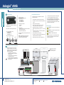
1
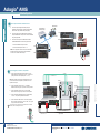
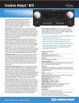
®
Adagio AMS
1
A.. Check Contents
A
B. Equipment/Tools Required
Depending on the configuration you ordered, you
should have received:
AMS, AMS-XM, or AMSI Adagio Media System
One or more Dual Radio Tuner(s)
ATC-AMFM2 Tuner
ATC-AMFMXM Tuner
ATC-AMFMSR Tuner
Antenna(s) supplied with tuner(s)
®
FM
AM
XM
•
•
Keypads and/or Controllers
C2N-DBF12
APAD
•
Optional Devices
CEN-IDOC Interface for Apple® iPod ® CEN-IDOC)
Adagio Audio Server (AAS)
Adagio Audio Expander (AAE)
•
•
•
®
NOTE: This system has specific out-of-the-box
functionality that is outlined in this guide. No
programming is required to get started!
•
CAT5/5E cables* for Ethernet connections (Step 3A)
RCA cables for connection of audio sources (Steps 3C & 5
E and F)
Wire lugs to attach the ground wires to the equipment.
* In order to ensure optimum performance over the full
range of your installation topology, Crestron Certified Wire,
and only Crestron Certified Wire, may be used for Cresnet and
CAT5 connections. Failure to do so may incur additional
charges if support is required to identify performance deficiencies because of using improper wire.
Cables for video sources (Step 2)
®
Cresnet cable* for network connection of Crestron
devices throughout the home (Steps 4 and 5)
C. Before Starting
Speaker wire (12 AWG max.) for connection of
speakers throughout the home. (Steps 2, 4A - C, & 5A and
B)
Speaker wire (10 AWG max.) for connection of speakers
in the home theater. (Step 2)
DHCP-enabled Ethernet router (Step 3A)
Grounding wire (16 AWG) For grounding audio equipment
together and connection to earth ground.
Appropriate hand tools (wire cutters, screwdrivers, etc.)
!
CAUTION: Do not connect power cords until instructed
to do so.
!
CAUTION: Do not run speaker wire parallel to electrical
wiring or Cresnet wiring.
!
CAUTION: Do not bridge amplifier outputs.
NOTE: Before beginning any of these QuickStart procedures,
make certain that all speaker wires and Cresnet cables are
installed throughout the home.
Connections for Theater Configurations
Default*
7.1 Theater + 4 Stereo Rooms
SCREEN
C
FR
SEATING
SR
SCREEN
C
FL
S
FR
S
HDMI
FL
COMPOSITE 1
•
•
S-VIDEO 1
COMPONENT 1
•
Pr
DISPLAY
*Two common theater configurations
are shown.
Refer to the AMS Operations Guide
for other possible configurations.
Optional*
5.1 Theater + 5 Stereo Rooms
SL
Outputs
BL
FL SL C
SEATING
SL
SR
FL SL C
FR SR S
Left
Right
Room 2
Room 1
Left
Right
Right
Right
S
+
–
–
+ –
+ –
OR
FL
FR
C
SL
SR
BL
From
Room 5
From Rooms 1- 4
BR
Left
Right
Speaker Level Outputs
1
For details, refer to the
AMS Operations Guide, Doc. 6509.
QUICKSTART DOC. 6510C (2015964)
07.13
www.crestron.com
Specifications subject to
change without notice
800.237.2041
201.767.3400
Right
Room 3
Left
AMS
Right
Room 4
Left
BR
BL BR FR SR S
Room 5
Left
Adagio AMS
Speaker level wiring is shown. Use pre-amp
connections if desired to connect to external
amplifiers. The sub woofer can be connected to
the RCA connector or the 3-position terminal
block connector as desired.
Use 12 AWG max. cables to the room
speakers; use 10 AWG max. cables to the
theater speakers.
Connect theater AV sources and display to
the appropriate connectors.
Control of the display is accomplished using
software tools. Refer to the AMS Operations
Guide for details.
Pb
2
•
•
Parts bag(s) containing connecting hardware, cables,
and adapters
Sirius
•
The following items are not supplied and are needed to
complete the installation:
AMS Operation Guide
AMS QuickStart Guide (this guide)
Operation Guide(s) for:
ATC-AMFM2 Tuner
ATC-AMFMXM Tuner
ATC-AMFMSR Tuner
Y
quickstart guide
Media System
®
Adagio AMS
quickstart guide
Media System
3 Connect Optional Network and Audio Sources
A.
Connect the optional Adagio Audio Server (AAS) and
CEN-IDOC to the AMS through a third party DHCP-enabled
Ethernet router using CAT5/5E cables (not supplied).
B.
Connect the docking station (CEN-IDOC-DS) supplied with
the optional CEN-IDOC to the port on the rear of the CEN-IDOC
using the supplied cable.
C.
DHCP-Enabled
Ethernet Router
CEN-IDOC-DS
AAS
CEN-IDOC
Connect the audio outputs of the CEN-IDOC and AAS to
available AMS SOURCES connectors using RCA cables:
•
•
AMS
Connect the CEN-IDOC outputs to source 5.
AAS
Connect the AAS outputs to sources 7 - 10.
NOTE: If the configuration includes an AAE, connect CEN-IDOC
and AAS audio outputs to the AAE loop through SOURCES
connectors, not to the AMS. Refer to Step 5.
AMS
CEN-IDOC
4
Connect Keypads, Controllers, and Speakers
A.
Connect the previously installed 16 AWG minimum (up to 12
AWG) speaker wire to the speakers in rooms 1 - 6. Observe the
polarity of the wires to each speaker (black = –, red = +).
Cresnet
From Rooms 1- 6
NOTE: Use speakers that are rated for full available output. Do not
connect more than two 8-Ohm speakers in parallel or one 4-Ohm
speaker to each output.
Rooms
5 - 6*
Connect the speaker wire from rooms 1 - 4 to the AMS
ROOMS connectors using the 2-pin socket connectors provided.
C.
Connect the speaker wire from rooms 5 or 6 to the AMS
BACK connectors using the 2-pin socket connectors provided.*
D.
E.
Right
Left
+
AMS
Connect the keypads (C2N-DBF12) and/or controllers (APAD)
in rooms 1 - 6 to previously installed Cresnet cables.
–
Rooms
1-4
+
APAD
Controller
OR
–
Connect the Cresnet cables from the rooms to the appropriate
NET connectors on the AMS (e.g., Room 1 to Net 1, etc.). Typical
wiring connections are shown below.
–+
*Connection to rooms 5 and 6 depend on the configuration selected. For detailed
information, refer to the AMS Operations Guide.
From Rooms 5 - 6
Red
White
2
Speaker Wire
Blue
Black
For details, refer to the
AMS Operations Guide, Doc. 6509.
QUICKSTART DOC. 6510C (2015964)
07.13
–
www.crestron.com
Specifications subject to
change without notice
800.237.2041
201.767.3400
Right
+ –
APAD
OR
Controller
From Rooms 1- 4
Right
Left
C2N
C2N-DBF12
N-DBF12
Ke
eypad
Keypad
OR
C2N-DBF12
C2N
N-DBF12
Ke
eypad
Keypad
Adagio AMS
B.
®
Adagio AMS
quickstart guide
Media System
5
Connect
o
Grounds
7 C
Connect the Optional Adagio Audio Expander (AAE)
The following steps can be performed in any convenient order. Steps A through D
are performed in the same way that similar connections were made to the AMS
(Step 4), and are not illustrated again here.
A.
Connect previously installed 16 AWG minimum (up to 12 AWG) speaker wire
to the speakers in rooms 7 - 12. Observe the polarity of the wires to each
speaker.
NOTE: Use speakers that are rated for full available output. Do not connect more
than two 8-Ohm speakers in parallel to each output.
B.
C.
Connect the speaker wire from rooms 7 - 12 to the AAE ROOMS connectors
(Rooms 1 - 6) using the 2-pin socket connectors provided.
D.
Connect the Cresnet cables from rooms 7 - 12 to the appropriate NET connectors 1 - 6 on
the AAE (e.g., Room 7 to NET 1, etc.).
E.
Connect the AMS NET and AAE NET LOOP THRU inputs using standard Cresnet cable.
F.
Connect the AMS theater downmix from the AMS OUTPUT connectors to the appropriate
available AAE SOURCES connector (default is 6).
NOTE: Specific connection to the AAE SOURCES connectors depends on the number and type
of optional audio sources used in the system. Refer to Step 3 and to the AMS Operations Guide
for details.
G.
Connect the keypads (C2N-DBF12) or controllers (APAD) in rooms 7 - 12 to
previously installed Cresnet cables.
Analog sources connect to the AAE SOURCES connectors; the sources are then shared
with the AMS ANALOG SOURCES connectors through the AAE loop through inputs. The wiring
method shown here is standard practice, but connections can be made to either side of the AAE
connector set.
Theater Downmix
Using 16 AWG wire with ground lugs (not
supplied), connect the ground terminals on
the rear of the AMS and the optional AAE to
a case screw on the rear of the optional AAS,
and to an earth ground. Chassis grounds
from external audio sources should also be
connected to the AMS ground screw.
AAS
AAE
AAE
AMS
Speakers
From Rooms 7 - 12
Cresnet
From Rooms 7 - 12
Cresnet
AMS
Earth
Ground
NOTE: If the Theater Downmix output
is connected to an AAE SOURCES
input, do not connect that loop through
connection to the AMS.
Theater
Downmix
6 Install Dual Tuner Cards
8
!
CAUTION: Do not connect external sources to SOURCES
connectors used by installed tuner cards.
Slot 1
Remove screws securing the plate covering the card slot to be
used. Insert the tuner card into the slot side rails, and make certain card
is fully seated before using the attached screws to secure it in position.
B.
Install tuner cards in Slots 1 and 2 only, for out-of-the-box functionality.
(One card may already be installed in Slot 1.) Either card may be
installed in either slot.
NOTE: The output of each dual tuner card occupies two of the ten
available source connections in the AMS. Slot 1 outputs are on
SOURCES 1 and 2, Slot 2 outputs are on SOURCES 3 and 4. After
installing the tuner card(s), the remaining connections may be used for
other audio sources.
C.
3
!
CAUTION: If you are adding Crestron
equipment beyond the devices mentioned in this
guide, be aware that insufficient power can lead to
unpredictable results or damage to the equipment.
Please use the Crestron Power Calculator, available
from the Crestron website (http://www.crestron.com),
to help calculate how much power is needed for the
system.
AMS
NOTE: Make sure that the power cord is not connected before installing
any tuner cards.
A.
For Future
Expansion
Slot 2
NOTE: The AMS, AAS, and AAE units do not have
a power switch. Power is applied to the units by
plugging in their respective power cords.
ATC-AMFM2
AM
Antenna
FM
Antenna
ATC-AMFMXM
AM
Antenna
FM
Antenna
AM
Antenna
XM
Antenna
FM
Antenna
ATC-AMFMSR
AM
Antenna
Sirius
Antenna
FM
Antenna
Connect the antennas included with the tuner cards. Refer to the
guide included with the tuner(s) for details on connection and antenna
placement.
For details, refer to the
AMS Operations Guide, Doc. 6509.
QUICKSTART DOC. 6510C (2015964)
07.13
www.crestron.com
Specifications subject to
change without notice
800.237.2041
201.767.3400
A.
Connect the AC power cord to the AMS and,
if applicable, to the optional AAS and AAE.
Then connect the power cord(s) to AC power.
B.
Connect power to all other system devices as
required. (Cresnet supplies power to the APAD
controller and the C2N-DBF12 keypads.)
Adagio AMS
!
CAUTION: Tuner cards are electrostatic-sensitive devices. Wear
a grounding strap or touch the metal chassis of a known
grounded device before handling and installing cards.
Apply Power
®
Adagio AMS
quickstart guide
Media System
9
Installer Tools Mode
In
Select Tuner Format
A.
A
Verify that power to the AMS is on. After a few seconds,
Loading . . . appears on the display. The unit then goes through an
internal startup procedure that takes about one minute.
B.
When the display shows a tuner source, press and hold the
SOURCE and ROOM buttons at the same time for about 10 seconds
to enter the Installer Tools mode. This mode provides a series of
menus and sub-menus, shown to the right, that let you perform a first
time setup and basic configuration options.
Do you want to install
a CEN-IDOC in your
system?
Yes
No
Configure Theater
Audio Configuration
Subwoofer
Front Center Speaker
Inputs
Restore Defaults
System automatically
populates this field with IP
address of your AMS.
Configure Network
Configure Network
Press the SETUP
button on the CEN-IDOC
Configure Network
Enter nnn.nnn.nnn.nnn
and IPID 03 on Crestron
Network Setup Screen
OK
Abort
Do you want to install
an AAS 1/2/4 in your
system?
Yes
No
Audio Configuration
7.1 Theater + 4 Stereo Roo
6.1 Theater + 4 Stereo Roo
6.1 Theater + 4 Stereo and
6.1 Theater + 5 Stereo Roo
5.1 Theater + 4 Stereo Roo
5.1 Theater + 5 Stereo Roo
Subwoofer
Front Center Speaker
Configure Input
Select Audio Source
Disabled
Enabled
Disabled
Enabled
Inputs
1: Movies
2: TV
3: DVD
Audio:
Video:
Name:
Audio:
Video:
Name:
Installer Tools
Select Tuner Format
Configure Network
Configure Theater
Configure Distributed Audio
Identify Keypads
Load APADs
About
SURRND
THEATER
DISPLAY
MORE
SOURCE
ROOM
HOUSE
MENU
Configure Network
Refer to the respective ATC Operations and
Installation Guide for information on the differences in radio station tuner format for each
selection.
Use soft buttons to make selections. Follow
screen instructions to configure.
1. Perform the functions in the order listed in the menu.
2. Use the Selection Knob to underscore each function and
press the Enter button to select it.
3. Follow the on-screen instructions for each function.
4. Press the Enter button to select an on-screen choice.
5. Use soft buttons to select choices at the bottom of a menu
screen.
6. The MENU button always takes you back to the Installer
Tools menu.
7. When all Installer Tools mode functions are completed,
use the MENU button to exit to Source mode.
Advanced setup information and operational details are given
in the AMS Operations Guide.
North American
European
Restore Defaults
Distributed Audio
Set number of AMS Rooms
Set number of AAE Rooms
Name AMS Rooms
Name AAE Rooms
Set AAE Theater Source
Name Sources
Hide Sources
Configure Keypads
Restore Defaults
Refer to the AMS
Operations Guide for
default values.
All Theater sources and
audio settings will be reset.
Continue?
Yes
No
Audio:
Video:
Name:
Select the number of
rooms that you will
be using on the AMS
4
Select the number of
rooms that you will
be using on the AAE
Yes
AAS-4 Configured
Assign to default
Theater Inputs?
No
Press Yes to accept the default
source assignments or press No
to skip the assignment. A source
assignment can be chosen while
configuring the theater. Refer to
the AMS Operations Guide for
details.
Select audio from the 10 analog, 6
digital coax, 4 digital optical, 1 multichannel and 3 HDMI sources, or [Not
Used] for video-only sources; press the
Enter button to select each choice.
Press the Done soft button when you
have finished making selections.
Select video from the 8 component, 4
S-video, 4 composite, and 3 HDMI
sources, or [Not Used] for audio-only
sources; press the Enter button to
select each choice. Press the Done
soft button when you have finished
making selections.
Use the Selection Knob to identify the
number of rooms for the AMS (1-4) and
the AAE (0-6) in this system; press the
Enter button to enter the value.
6
Soft Buttons
AMS
Selection Knob
Name AMS Rooms
Volume Knob
1: AMS Rm 1
2: AMS Rm 2
3: AMS Rm 3
Press the Edit soft button to
change the Room names for
easier identification. You can Select AMS Room 1 Na
also use the Selection Knob 1: Room 1
2: Room 2
to scroll through the list of
3: Room 3
default names.
Del
<
>
Done
Refer to the AMS Operations
Guide for details.
Edit
Enter Button
Mute Button
Theater Off Button
Room All
Buttons Off
Media
Buttons
Name AAE Rooms
1: AAE Rm 1
2: AAE Rm 2
3: AAE Rm 3
Edit
Set AAE Theater Source
Select the input to use for
the theater down-mix input
on the AAE 6
4
For details, refer to the
AMS Operations Guide, Doc. 6509.
QUICKSTART DOC. 6510C (2015964)
07.13
www.crestron.com
Specifications subject to
change without notice
800.237.2041
201.767.3400
Press the Del soft button to delete
the current name. Use the Selection
Knob to scroll through the letters;
press the Enter button to select each
choice. Use the < and > soft buttons
to move the cursor left and right.
Press the Done soft button when the
name is finished. Repeat for each
room name.
Adagio AMS
Refer to
Page 5
Select Video Source
Number Of AMS Rooms
Number Of AAE Rooms
Refer to
Page 5
Done
Configure Network
®
Adagio AMS
quickstart guide
Media System
9 IInstaller
ns
Tools Mode (Continued)
10
A
After
the Installer Tools mode functions are
finished, press a ROOM button, then press the
Source soft button and use the Selection
Knob to select available audio and video
sources. Adjust the Volume Knob as necessary; press the MORE button to adjust the tone
controls, and verify basic operation of your
Adagio Media System.
Refer to
Page 4
Distributed Audio
Set number of AMS Rooms
Set number of AAE Rooms
Name AMS Rooms
Name AAE Rooms
Set AAE Theater Source
Name Sources
Hide Sources
Configure Keypads
Restore Defaults
Select Source to Name
1: Source 1
2: Source 2
3: Source 3
Select Source to Name
1: [Custom Name]
2: Source 2
3: Source 3
Edit
Edit
Press Enter or the Edit
soft button to change
source names for easier
identification.
Hide Sources
1: Source 1
2: Source 2
3: Source 3
Hide Show
Select Button to Map
Btn1: Source 1
Btn2: Source 2
Btn3: Source 3
1: [Custom Name]
2: Source 2
3: Source 3
Del
<
>
Done
Use the Selection Knob to choose [Custom Name] or one of
several preset names. Press Enter to accept the choice. If a
preset name is selected, that name appears for the source. If
[Custom Name] is chosen, press the Edit soft button to enable
entering a preferred name for the source.
Select Src. for Button 2
Btn1: Source 1
Btn2: [CEN-IDOC]
Btn3: AM/FM Tuner
Done
Identify Keypads
Identify Keypads
Warning:All keypads will
need to be re-identified
Continue?
Yes
No
Warning:
All room APADs will be
loaded with default
functionality. Continue?
Yes No
System Information
Addr: 192.168.121.2
Mask: 255.255.255.0
Host AMS000107F01B53D
Select keypad type
for Theater
APAD
None
11
Press any key
on the APAD in
Theater
Identify Keypads
Select keypad type
for Room 1
APAD
12 But
For theater setup, press the THEATER button
and then press the THEATER and MORE
buttons simultaneously for about three seconds.
The screen shows three parameters that you can
adjust to set the minimum, maximum, and starting volume for the theater. Use the soft buttons to
select the parameter, and use the Selection
Knob to adjust the level.
Identify Keypads
Press any button
on the keypad in
Room 1
Room 1
Select Parameter
to Adjust
MinV MaxV StartV Mono
Room 1
Min Volume 5%
Theater
Select Parameter
To Adjust
Min V Max V Start V
None
Refer to the AMS
Operations Guide for
default values.
The specific patents that cover Crestron products are listed at patents.crestron.com.
Crestron, the Crestron logo, Adagio, and Cresnet are either trademarks or registered trademarks of Crestron Electronics, Inc. in the United States
and/or other countries. Apple and iPod are either trademarks or registered trademarks of Apple, Inc. in the United States and/or other countries.
SIRIUS, the SIRIUS logo, XM, and the XM logo are either trademarks or registered trademarks of SIRIUS XM Radio Inc. in the United States and/or
other countries. Other trademarks, registered trademarks, and trade names may be used in this document to refer to either the entities claiming the
marks and names or their products. Crestron disclaims any proprietary interest in the marks and names of others. Crestron is not responsible for
errors in typography or photography.
07.13
Off
Reset
Press the SOURCE button and select a source.
Then press the SOURCE and MORE buttons
simultaneously for about three seconds. The
screen shows a gauge for the current gain
setting of the selected source. Use the Selection Knob to adjust the gain as desired. (Use
the Reset soft button to reset the gain to 0dB.)
Repeat for each source.
Refer to the AMS Operations Guide for more
details on operation of the system.
For details, refer to the
AMS Operations Guide, Doc. 6509.
QUICKSTART DOC. 6510C (2015964)
Source Bklt
Default functionality of any
C2N-DBF12 connected to
the AMS.
This document was written by the Technical Publications department at Crestron.
©2013 Crestron Electronics, Inc.
5
Dolby Digital 5.1
Room and Source Setup
Press the ROOM button and select a room.
Press the ROOM and MORE buttons simultaneously for about three seconds. Then, follow the
screen instruction and use the soft buttons to
select each parameter to be adjusted. The
screen shows a gauge for the selected parameter at its current value. Use the Selection
Knob to adjust the value as desired. Press the
MENU button to choose a different parameter.
Repeat for each room.
Refer to the AMS
Operations Guide for
default values.
Identify Keypads
Theater
TV
www.crestron.com
Specifications subject to
change without notice
800.237.2041
201.767.3400
Source 1
88.00 FM
Mono
Control
Source 1
Gain 0dB
Reset
Adagio AMS
All Audio Distribution
source and audio settings
will be reset. Continue?
Yes
No
To verify the Theater operation, press the
THEATER button. Press Source and use the
Selection Knob to choose different sources.
Press the Bklt soft button to adjust the display
illumination; press the Off soft button to turn off
the theater zone audio (the button legend
changes to On). Press the button again to turn
the audio back on. Adjust the Volume Knob as
necessary; press the MORE button to adjust the
tone controls.
C2N-DBF12
Use the Selection Knob to select
the C2N-DBF12 button to map.
Press the Edit soft button, and
use the Selection Knob to select
the source. Refer to the diagram
on the right for the position of
buttons 1 - 6.
Use the supplied button caps to
label the buttons to match the
source selections.
Refer to the Operations manual
for the C2N-DBF12 as necessary
to install the button caps.
Restore Defaults
Identify Keypads
Load APADs
About
Press the Del soft button to delete the
current name. Use the Selection Knob
to scroll through the letters; press the
Enter button to select each choice. Use
the < and > soft buttons to move the
cursor left and right. Press the Done
soft button when the name is finished.
Repeat for each source name.
Refer to the AMS Operations Guide for
details.
Use the Hide and Show soft buttons to hide or show the
names of each source (up to 10 plus the Theater Source)
connected to the system.
Refer to the AMS Operations Guide for details.
Edit
Refer to
Page 4
Enter Source 1 Name
Verify Operation
V