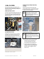
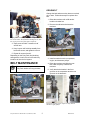
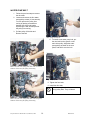
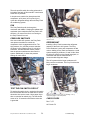
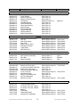
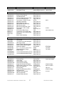
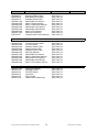
1
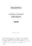
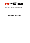
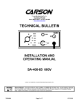
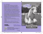
OWNER’s
MANUAL
Model 2004/06
UNIT SERIAL NUMBER
Pony Pack Inc.
Albuquerque, NM
(505) 243-1381
DATE:
FOR YOUR IDLE TIME……
Pony Pack Owner’s Manual Rev. 00, March 26, 2008
Cover Page
FILTER AND BELT INFORMATION
Washable Air Filter
Wash and Re-oil
Pony Pack
As Needed
105-0515-0
Drop-In Fuel Filter
Replace
Pony Pack
Kubota
600 Hours
105-0507-0
15231-43560
In-Line Fuel Filter
Replace
Pony Pack
Baldwin
NAPA
Kubota
6 Months
105-0508-0
BF840
3389
12581-43012
Main Drive Belt Model 2004
Pony Pack
2004-0110-0
Gates Rubber Co.
K060465
Main Drive Belt-Model 104 & 105
Pony Pack
105-0113-0
Gates Rubber Co.
K060435
Goodyear
4060435
Dayco
435K6
Oil and Filter
Replace
Pony Pack
AC
Baldwin
Carquest
Donaldson
Fleetguard
Fram
Kubota
Lubefiner
Mobile
Shell
STP
Transicold
Wix
Yanmar
150 Hours*
105-0115-0
PF1127
B179
85334
P550162
LF3462
PH3593A
15853-32430
PH2802
MO4459
SH521
SO2808
2535206
51064
124450-35100
Water pump Belt
Pony Pack
Gates Rubber Co.
Goodyear
Dayco
2004-0114-0
7250
13251
15250
*Change oil filter after first 50 hours of use
Oil capacity with filter change is 2.33 quarts
Do not use synthetic oil during first 500 hours
ABOUT THIS MANUAL
This manual is intended to help the owner understand the Pony Pack features and
operation. It is not an installation manual nor a shop or service manual. Service and
maintenance information included herein is limited to routine maintenance procedures
and simple troubleshooting which a mechanically inclined owner could undertake.
Pony Pack provides specific installation information to the installing shop whenever
possible. Wiring schematics and plumbing guidelines included in the back of this
manual are a reference for the owner to pass along to service personnel only. Pony
Pack technical assistance is available by calling 505-243-1381.
California Proposition 65 Warning
Diesel engine exhaust and some of its constituents are known to cause cancer, birth
defects, and other reproductive harm.
Pony Pack Owner’s Manual Rev. 00, March 26, 2008
ii
Cover Page
Pony Pack Registration Form
You should have two copies of this form: One in your manual for your records, and one to return to Pony
Pack. Please complete this form and mail it in. This information helps us better serve our customers and
process warranty claims and parts orders. Send the completed form to:
Pony Pack, Inc.
1407 University, NE
Albuquerque, NM 87102
INTALLATION DATE:
SERIAL NUMBERS
PONY PACK SERIAL NUMBER __________________________________________
KUBOTA ENGINE SERIAL NUMBER ______________________________________
MODULE SERIAL NUMBER _____________________________________________
SELLER
NAME _______________________________________________________________
ADDRESS ____________________________________________________________
CITY/STATE/ZIP _______________________________________________________
PHONE(S)/FAX ________________________________________________________
INSTALLER
NAME _______________________________________________________________
ADDRESS ____________________________________________________________
CITY/STATE/ZIP _______________________________________________________
PHONE(S)/FAX ________________________________________________________
OWNER
NAME _______________________________________________________________
ADDRESS ____________________________________________________________
CITY/STATE/ZIP ________________________________________________________
TRUCK (YEAR, MAKE, MODEL) ___________________________________________
ENGINE (MAKE, MODEL) ________________________________________________
PHONE(S)/FAX _________________________________________________________
Pony Pack Owner’s Manual Rev. 00, March 26, 2008
iii
Registration Form
TABLE OF CONTENTS
Contents
Page
Warranty ............................................................................ v
Safety.................................................................................1
Operating Instructions........................................................3
Maintenance ......................................................................5
AC Clutch Switching ........................................................13
Troubleshooting ...............................................................17
Parts and Service.............................................................25
Model 2004/06 Wiring Schematic
Switch Four Schematics
Engine Plumbing Guidelines
Pony Pack Owner’s Manual Rev. 00, March 26, 2008
iv
TOC
WARRANTY
Pony Pack, Inc. (“Pony Pack”) provides the following warranty which defines the extent
of protection and assurance to the owner of a Model 104, 105, or 2004 Pony Pack
Auxiliary Power Unit (“APU”).
THIS WARRANTY HAS BEEN DELIVERED TO THE FIRST OWNER OF THE APU AT THE TIME OF
INSTALLATION. IF THERE ARE ANY TERMS, PROVISIONS OR CONDITIONS OF THIS WARRANTY
WHICH ARE NOT CLEARLY UNDERSTOOD AT SUCH TIME BY THE FIRST OWNER, THEN THE
FIRST OWNER SHOULD OBTAIN SATISFACTORY WRITTEN CLARIFICATION OF THE WARRANTY
SIGNED BY AN AUTHORIZED REPRESENTATIVE OF Pony Pack PRIOR TO PLACING THE APU IN
SERVICE.
COVERAGE
BASIC COVERAGE:
Pony Pack warrants (subject to all terms, provisions, conditions, and limitations of this Warranty) that
each APU will be free from defects in material and workmanship under normal use and service for a
period of one year from the date of installation for first use, or 2,000 hours of operation, whichever comes
first, with a possible longer period of Warranty for specified components of the APU as set forth below.
PONY PACK’S WARRANTY OBLIGATION:
Pony Pack’s sole obligation under this Warranty shall be to repair or replace, at Pony Pack’s option, any
defective component or material (“Defect”) constituting a part of the APU. Upon determination by Pony
Pack of the existence of a Defect, such repair and replacement shall be without cost to the first owner of
the APU (“First Owner”) when performed by Pony Pack at Pony Pack’s location or at a qualified,
authorized repair facility.
ENGINE, AIR CONDITIONING COMPRESSOR AND ALTERNATOR:
Pony Pack will assign the benefit of any assignable warranties provided by the manufacturers of
components of the APU. Copies of all written warranties on the components are attached as an exhibit to
this Warranty and each should be read and complied with fully in order to obtain the maximum benefit
from any such warranty. Pony Pack makes no warranties or representations concerning the extent or
enforceability of any warranty from a manufacturer of components or about any requirements imposed by
the manufacturers of components of the APU.
INSTALLATION AND MAINTENANCE:
At the time of installation of the APU, its operation shall be inspected and adjusted. Such inspections and
adjustments include but are not limited to checking engine performance, performance of fuel system,
coolant pump function, air conditioning system integrity and performance, performance of controls, and
electrical system integrity and performance. Proper use of the APU requires that all such inspections and
adjustments shall be properly maintained at all times according to the schedules of recommended
maintenance outlined in the instruction manual of the APU. As a condition of claiming benefits under this
Warranty, Pony Pack reserves the right to require written proof, satisfactory to Pony Pack, in the form of
receipts for maintenance on the APU and other service records to establish that all such maintenance
and service has been performed as required by this Warranty and as recommended in the instruction
manual of the APU.
Pony Pack Owner’s Manual Rev. 00, March 26, 2008
v
Warranty
TERMINATION OR VOIDING OF WARRANTY:
Repair or replacement, other than routine maintenance using approved parts and supplies, or
modification of the APU by anyone other than Pony Pack representatives or employees of a qualified,
authorized repair facility using authorized parts and materials shall void this Warranty. This Warranty also
shall be void if the Defect or necessity for replacement or repair, in Pony Pack’s opinion, is due in whole
or in part to improper installation of the APU by some entity other than Pony Pack, improper maintenance
or service of the APU, modification or alteration of the APU after installation, damage due to accident
and/or any other misuse or abuse of the APU. Following expiration of the warranty period, Pony Pack’s
obligation hereunder shall terminate. Repair and replacement of components of an APU under this
Warranty shall not extend the warranty period for the APU or for any component, material or part thereof
except as noted in assigned warranties from manufacturers of components of the APU.
EXCLUSIONS FROM WARRANTY
THIS WARRANTY DOES NOT INCLUDE THESE ITEMS:
To better understand our warranty, the following is a description of some conditions which are not
covered by this warranty.
NORMAL MAINTENANCE AND REPLACEMENT SERVICES:
Pony Pack is not responsible for the cost of tune up of the APU engine or other maintenance, adjustment
and inspection services which may be required including repair or replacement of valves, injectors, fuel
system, filters (fuel, air, oil, and water), hoses, and tightening of clamps and fasteners which may loosen
in service due to vibration, expansion and contraction due to heating and cooling, and road shocks.
INCIDENTAL AND CONSEQUENTIAL DAMAGES AND COSTS:
Pony Pack specifically denies and disclaims any liability or responsibility under this Warranty or otherwise
for injuries to persons or property, traveling expenses, road calls, towing charges, accident repairs, loss of
revenue, loss of perishable loads, profits and/or anticipated profits, and loss of truck use. Pony Pack shall
not, under any circumstances, be liable for special, incidental or consequential damages.
MAXIMUM LIABILITY:
Pony pack’s liability on any and all claims under this Warranty and under any and all theories of liability
for any loss or damage arising out of, concerning, resulting, arising from or related to the contract of sale,
delivery, service, repair or use of an APU manufactured by Pony Pack shall not in the aggregate exceed
the original installed price of the APU.
DISCLAIMER OF OTHER WARRANTY CLAIMS:
This written Warranty is exclusive and in lieu of all other warranties, whether written, oral, or implied. Pony
Pack makes no other warranty except as expressly stated herein. There are no other express warranties,
implied warranties, warranties of merchantability, or warranty of fitness for particular purpose with respect
to the APU unless they are specifically stated herein.
WARRANTY PROCEDURES
NOTICES:
Any notice given by the Owner of an APU to Pony Pack shall be in writing, signed by the Owner and shall
be personally delivered to Pony Pack or sent by U. S. Mail, postage prepaid, certified, Return Receipt
Requested, to Pony Pack at its business office or transmitted in facsimile to Pony Pack at its business
office:
Pony Pack, Inc.
1407 University, NE
Albuquerque, New Mexico 87102
FAX (505) 243-1384
Pony Pack Owner’s Manual Rev. 00, March 26, 2008
vi
Warranty
Such notice shall be effective (a) immediately upon personal delivery to a representative of Pony Pack at
Pony Pack office, (b) three days after being deposited in the mail as to notices which are mailed, or (c)
two days after delivery of the notice by facsimile.
WARRANTY CLAIM PROCEDURE:
In order to claim benefits under this Warranty, Pony Pack must be notified in writing within the applicable
Warranty period of the failure of the APU to comply with this Warranty. Any claim under this Warranty
must be promptly followed, at expense of the Owner, by delivery to Pony Pack or its qualified, authorized
service facility, of the APU (or of the component or material from the APU which is claimed to be
defective). Pony Pack reserves the right to inspect for defects of workmanship, parts and materials and its
decision with respect to such matters shall be final.
TRANSFER OF WARRANTY:
Pony Pack extends this Warranty solely to the First Owner. Any unused Warranty time of the First Owner
may be transferred to a subsequent owner of the APU only after approval by Pony Pack of a written
request for the transfer. Any written request for transfer of this Warranty shall disclose the name and
address of the intended subsequent owner and shall verify the date of installation of the APU for first use,
the total hours of operation of the APU, the condition of the APU and that all recommended maintenance
has been performed by qualified, authorized service facilities using only approved parts and materials
(excepting only those items of routine maintenance performed by others in accordance with the
instruction manual of the APU).
GOVERNING LAW AND RESOLUTION OF DISPUTES:
This Warranty is extended under the laws of the State of New Mexico, the state in which Pony Pack is
incorporated, has its primary place of business and has manufactured the APU. All questions concerning
the interpretation or enforcement of this Warranty shall be governed and construed according to the laws
of the State of New Mexico. By acceptance of this Warranty, the Owner of each APU agrees that any
litigation and the resolution of any dispute between Pony Pack and the owner of an APU shall be
conducted solely and exclusively in the state or federal courts of the State of New Mexico. Any action of
any kind in any other forum or jurisdiction shall be subject to dismissal or to removal, at the discretion of
Pony pack, and the party filing such action shall pay all costs including reimbursement of Pony pack’s
attorneys’ fees in obtaining such dismissal or removal.
Pony Pack Owner’s Manual Rev. 00, March 26, 2008
vii
Warranty
Pony Pack Owner’s Manual Rev. 00, March 26, 2008
viii
Warranty
Safety
Congratulations on your Pony Pack purchase.
SPECIAL SYMBOLS
Please, read this manual completely. Contact
Pony Pack or your dealer if you have questions.
Failure to follow the procedures in this manual
could void your warranty. Improper installation
and usage can cause serious injury to personnel
and/or damage to the Pony Pack or the
equipment on which it is installed.
If after reading the information contained herein,
you still have questions, please contact Pony
Pack or your dealer promptly.
SAFETY
Safety is everybody’s business and everybody’s
responsibility. Each truck and Pony Pack
installation is different, so assess all safety
concerns peculiar to your situation. Be attentive.
Watch for hazards and correct them immediately.
Use preventative measures. Exercise common
sense.
Many of the safety guidelines set forth are
applicable to general plant and equipment safety
practices. However, this document is specific to
Pony Pack products. This information is not a
comprehensive shop or equipment safety
standard. Pony Pack is not responsible for any
accidents that may occur simply because a
specific warning has not been made here.
Qualified shops and certified mechanics are
familiar with the hazards of working around heavy
equipment and diesel engines. Pony Pack
recommends that only qualified mechanics install
and conduct maintenance and repairs on Pony
Packs.
Certain special symbols are used throughout
Pony Pack documentation to identify potential
safety hazards. Pay close attention and read the
text carefully whenever you encounter any of
these symbols.
This symbol identifies possible
electrical hazards or conditions.
This symbol identifies possible
mechanical hazards or conditions.
This symbol identifies pinch point
hazards. It warns the reader to keep
hands and fingers clear of the hazard.
This symbol identifies situations where
the worker may be inclined to take a
shortcut or use the wrong tool.
CALIFORNIA
PROPOSITION 65
WARNING
Diesel Engine Exhaust and some of its
constituents are known to cause cancer, birth
defects, and other reproductive harm.
SAFE PONY PACK
OPERATION
• Before operating the Pony Pack, read
and understand all manuals, including
enclosures and insertions for other
manufacturer’s equipment.
• Always dress for safety. Secure long
hair, loose clothing, and jewelry to keep
it clear of operating equipment. Have eye
protection routinely available and use it
when directed or when common sense
dictates.
Pony Pack Owner’s Manual Rev. 00, March 26, 2008
1
Safety
WARNING LABELS
• Disable and discard unsafe components
and items that have been removed or
replaced during maintenance and repair.
Pay attention to all warnings on the Pony Pack.
Never remove or cover warning labels. Never
assume the equipment is safe simply because
there is no warning label.
• Follow your company’s safety
procedures and guidelines at all times.
• Stay clear of the belts on the Pony Pack,
even when it is not moving.
SAFE HANDLING OF FLUIDS AND
CHEMICALS
• Frequently inspect wires. They must be
secured away from moving parts and
protected by conduit where possible.
Follow manufacturer’s instructions and the
regulations in your area for safe handling, usage,
and disposal of engine coolant (antifreeze),
engine oil, Freon, and any other fluids used in
your truck or Pony Pack. Most manufacturers will
provide a Material Safety Data Sheet, MSDS, for
the materials they sell.
• Frequently inspect the hoses and
connections. Look for spots where they
may be rubbing. Use cushions and tie
straps to protect hoses as needed from
abrasion.
KUBOTA ENGINE
MANUAL
• Do not operate the Pony Pack with the
cover off, except as needed by qualified
maintenance personnel. During such
maintenance, all other personnel should
stand clear of the unit.
The central Pony Pack component is a Kubota
two-cylinder diesel engine. Pony Pack includes
the Kubota Diesel Engine Operator’s Manual with
every Pony Pack sold. The same manual covers
three Kubota engine models. The Pony Pack uses
the Z482-E.
• Do not insert objects, fingers, or tools
into the unit. Take extra care to retrieve
all tools after working on the unit. Tools
and objects left in or on the equipment
may seriously damage the Pony Pack
and create a safety hazard for persons
working in the area.
THIS MANUAL
The different sections in this manual discuss most
aspects of a Pony Pack operation and routine
maintenance. Photos and diagrams help provide
clarity. Understand that the photos show general
features and may not depict the exact orientation
or appearance of each installation. Pages and
foldouts at the back of this manual are included as
a reference to assist qualified mechanics.
• Altering the Pony Pack RPM will void the
warranty.
• Modifications are not permitted.
• Use only the Pony Pack (AFE brand) air
filter oiling agent on the Pony Pack air
filter.
DISCLAIMER
• Avoid skin and eye contact with the air
filter cleaning solution.
It is very important that the truck’s A/C, coolant,
and fuel systems be free of leaks and
contamination before installing a Pony Pack. Pony
Pack, Inc. is not responsible for damage to any
truck systems due to faulty equipment,
contamination, Freon, fuel, or coolant leaks, or
Pony Pack installation or operation not in
accordance with this manual.
• Never stand on the Pony Pack or use it
as a step.
Pony Pack Owner’s Manual Rev. 00, March 26, 2008
2
Safety
Operating
Instructions
This document explains how to preheat, start,
and operate model 2004 Pony Packs. A properly
installed Pony Pack is designed to operate without
keys in the truck ignition. If for some reason the
Pony Pack shuts down, all Pony Pack 12 volt
functions will disengage to prevent battery drain.
Never start or operate the Pony Pack
with
the cover removed. Only qualified shop
personnel should operate the Pony
Pack without the cover in place.
Hour Meter: The hour meter runs when the unit is
running.
Green Light: The green light stays illuminated
while the unit is preheating or running.
A flashing green light indicates a system
malfunction. For more information, remove the
cover and see what red light on the module is lit.
IGN/OFF
START
switch: Pony Pack ignition.
switch: Preheats and starts the Pony Pack.
CAB HEAT/OFF switch: Turns the in-line coolant
pump on or off for cab heating.
MAIN/AUX switch: Transfers all heating, ventilating,
and air conditioning functions between the truck
engine (MAIN) and Pony Pack (AUX).
The Pony Pack control panel has four switches,
an hour meter, and a green indicator light.
START-UP PROCEDURE
CONTROL PANEL
Never start the Pony Pack with the
MAIN/AUX switch in the AUX position. This
may turn on A/C or electric loads and
overload the starter.
1. Turn the Pony Pack IGN switch on.
The green light will blink on and off
once.
2. Push the spring-loaded START switch
to the right and release. The green
light will illuminate indicating
automatic glow plug operation.
Holding the START switch does not
affect the preheat duration.
Pony Pack control panel
NOTE: Preheat duration is automatically
determined by the coolant temperature in
the Kubota engine.
3. When the green light goes off, hold
the START switch to the right until the
unit sounds like it is revving under its
own power. THE UNIT WILL NOT
START UNTIL THE GREEN LIGHT
SHUTS OFF.
Pony Pack Owner’s Manual Rev. 00, March 26, 2008
3
Operating Instructions
4. When the green light stays on, the
unit is running. NOTE: If you do not
start the unit within five minutes of
preheating, repeat steps 1, 2 and 3.
needed for cooling. When the switch is in the MAIN
position, the truck air conditioning sensors and
controls activate the truck compressor as needed
for cooling.
5. If the unit does not start, turn the
Pony Pack ignition switch off and
back on to reset the control module.
Obviously, since an A/C compressor is a belt
driven accessory, the truck engine must be
running to use the truck compressor. Likewise the
Pony Pack must be running to use the Pony Pack
compressor. If both the truck and Pony Pack are
running, switching the MAIN/AUX switch determines
which compressor operates.
SHUTDOWN
PROCEDURE
The CAB/HEAT switch should be OFF and the
MAIN/AUX switch should be in MAIN position before
shutting off the Pony Pack.
To shut off the Pony Pack, turn the IGN/OFF switch
to OFF.
CAB HEAT
PUMP OPERATION
The cab heat switch controls only the electric
pump installed in the heater supply line. The
dashboard heater controls determine temperature,
fan speeds, etc.
Do not operate the cab heat pump if the
heater core supply valve is off.
Operating the cab heat pump without
coolant flow causes it to cavitate and
subsequently burn out.
On trucks equipped with the Index
Industries Air Conditioning Protection
and Diagnostics System, APAds (Volvo
610, 660, 770 and some other
makes/models with factory or
aftermarket APAds systems), BEFORE
switching the MAIN/AUX switch in either
direction, the dashboard A/C control
MUST BE TURNED OFF to prevent a
false malfunction code on the APAds
module. The momentary power
interruption registers as a false loss of
electrical power to the A/C system
causing technicians to waste time
looking for a bad connection that does
not exist.
SIMULTANEOUS
OPERATION
A properly installed Pony Pack should operate
whether the truck engine is running or not. Two
scenarios are listed below.
AIR CONDITIONING
OPERATION
• Occasionally, a driver may engage Pony
Pack cooling while driving to reduce the
compressor and cooling fan parasitic
loads on the truck engine.
The A/C system on a truck requires constant 12
volt power to operate the compressor, blower
motors, thermostat, and climate control
components. A properly installed Pony Pack
provides 12 volt power to these components as
needed for the system to operate properly.
• The Pony Pack will keep the batteries
charged in the event the truck alternator
fails.
A Pony Pack equipped truck has two A/C
compressors. The MAIN/AUX switch on the Pony
Pack control panel switches between the
compressors. Activating one system deactivates
the other. In other words, both compressors can
never operate simultaneously.
When the MAIN/AUX switch is in the AUX position,
the truck air conditioning sensors and dashboard
controls activate the Pony Pack compressor as
Pony Pack Owner’s Manual Rev. 00, March 26, 2008
4
Operating Instructions
Maintenance
Properly maintain your Pony Pack for peak,
trouble-free performance. Follow all safety
guidelines. If you are unsure about any
maintenance procedure, contact Pony Pack or
consult a qualified mechanic. Failure to conduct
scheduled maintenance may void the Pony Pack
warranty. Approved filters and belts are listed on
the inside cover of this manual.
Conduct all maintenance procedures
with the Pony Pack turned off.
SERVICE MODE
By design, the Pony Pack electronic control
system shuts down electrical functions (fuel pump,
heat exchanger motor, fan, coolant pump etc.) if
the engine is not started within two minutes of
turning the IGN/ON switch to the ON position. (This
prevents battery drain in the event the Pony Pack
shuts down.) It is possible to initiate a service
mode which will energize some of the electrical
components as needed to purge air from the fuel
system or perform other diagnostics. Follow these
steps to get the Pony Pack control system into the
service mode.
The reset wire is a short white wire in the green module
connector.
1. Turn the IGN/OFF switch to IGN.
2. Within two minutes, momentarily ground
the short white wire from the green
module connector by carefully touching
the end of it to the metal module bracket.
Touch the white wire to the corner of the module bracket.
3. The ignition circuit will remain on for 15
seconds and the module OIL LED will
flash for 15 seconds then go solid. The
fuel pump will run for an additional 15
seconds each time the white wire is
grounded to the bracket.
OIL CHANGE
The oil drains more completely when
hot. Avoid touching hot engine surfaces
while changing the oil and filter. Use
gloves, a rag, or a wrench to remove the
oil filter.
BREAK-IN
The Kubota engine break-in period is
approximately 500 hours. During this period, you
may experience some oil consumption. Change
Pony Pack Owner’s Manual Rev. 00, March 26, 2008
5
Maintenance
the engine oil and filter after the first 50 hours of
use and every 150 hours thereafter.
thin film of oil to the new filter gasket before
installing it. Tighten the new filter by hand.
REGULARLY SCHEDULED OIL CHANGE
Add oil. The capacity is 2.33 (two and one-third)
quarts.
Change the Kubota engine oil every 150 hours.
Replace the filter at every oil change. Use a 22
mm socket to remove the drain plug.
Close-up of the end of a dipstick.
Remove the drain plug with a 22 mm socket.
OIL TYPE
Use the same oil in the Pony Pack as in the truck
engine. Pony Packs are shipped from the factory
with Rotella T 15W-40 in the crankcase.
A NOTE ABOUT SYNTHETIC OIL
Do not use synthetic oil in the Kubota
engine during the first 500 hours of
operation. Thereafter, synthetic oil use is
permitted. Synthetic oil use does not
increase the oil change interval.
AIR FILTER
Unscrew the filter cartridge. Use the bottom one inch of an
oil or antifreeze jug to catch any oil that spills out of the
filter and engine. Use rags to keep oil out of the alternator.
The air filter element is a washable reuseable air filter. DO NOT THROW IT
AWAY.
Always cover the alternator to prevent oil
from dripping into the windings. Engine
oil has a documented detrimental affect
on alternator performance.
Cut off the bottom one inch of a used oil or
antifreeze jug. Position it under the oil filter to
catch the small amount of oil that spills out.
Unscrew the filter cartridge. Wipe the gasket
surface on the engine with a clean rag. Apply a
Pony Pack Owner’s Manual Rev. 00, March 26, 2008
6
Maintenance
AIR FILTER CLEANING
Only use AFE brand air filter cleaner and
filter oil. Use of pressurized water,
compressed air, open flame, hot air
dryers, gasoline, or other caustic
cleaning solutions will void your
warranty.
Follow the instructions on the cleaning agent and
oil bottles to clean the filter element. Those
instructions are repeated here.
1. Spray on the cleaner and let stand 10
minutes.
Pony Pack air filter and cleaning kit.
A new Pony Pack comes with a cleaning kit.
Inspect the air filter. Wash and oil it when it is dirty
or when restricted air flow causes the engine to
smoke. A collapsed air intake hose may indicate
restricted air flow.
AIR FILTER REPLACEMENT
Follow these steps to change the air filter.
1. Loosen both hose clamps on the air
intake hose.
2. Rinse with tap water. Let dry
completely.
3. Apply AFE Oil to the filter. Leave
about 1/2 inch gap from the edge. Oil
will spread to the edges in about 45
minutes to one hour. Check for light
areas and apply a small amount if
needed. Uniform oil coloring through
filter media ensures properly oiled
filter.
Uniform oil coloring through filter media
ensures properly oiled filter.
2. Rotate the hose connection on the
engine clockwise. Remove the filter from
the filter sleeve.
Keep your AFE air filters oiled and
never operate your vehicle when the
filter is not oiled. Do not over oil. The
included cleaning kit should be good
for ten cleanings.
Additional filters and cleaning supplies
are available from Pony Pack.
Air intake hose rotated up to access the filter.
3. Install the cleaned and oiled filter into the
filter sleeve.
4. Rotate the air intake hose back into
place and tighten both hose clamps.
Pony Pack Owner’s Manual Rev. 00, March 26, 2008
7
Maintenance
PURGE THE AIR FROM THE FUEL
SYSTEM
.FUEL FILTERS
The Pony Pack utilizes two fuel filters: in-line
between the truck fuel tank and Pony Pack, and a
drop-in filter and bowl assembly preceding the
engine injector pump.
DROP-IN FUEL FILTER
Pony Pack recommends replacing the drop-in fuel
filter every 600 hours. Use channel lock pliers to
unscrew the filter bowl nut. When finished, fingertighten the filter bowl nut then add 1/4 turn with
channel lock pliers.
Drop-in filter bowl removed
Always purge the air from the system after
servicing either fuel filter. The photo below shows
the three screws that are loosened one at a time
to purge air from the fuel system.
Leave the fuel bowl pet-cock in the
vertical position. It serves no useful
purpose within the Pony Pack fuel
system. More recent Pony Packs have
the pet-cock removed.
Three purging screws: (1) and (2) on the aluminum filter
body and (3) on the injector pump.
IN-LINE FUEL FILTER
Change the in-line fuel filter every six months, or
more often if you suspect it may be dirty or you
had a bad tank of fuel. Loosen the two hose
clamps that hold the filter in place, pull out the old
filter, and install the new filter.
Screws 1 and 2 install into an aluminum
body. Barely tighten them to prevent
stripping out the housing. Some drivers
find that finger tight is adequate and they
never use a wrench.
1.Use the bottom one-inch cut from a plastic
oil bottle to catch fuel that drips out.
Cover the compressor with rags to
prevent diesel fuel from spilling onto it.
2. Touch the white wire from the green
module connector to the module bracket
to begin the service mode and start the
fuel pump. (Note: Toggle the IGN/OFF
switch to IGN.)
In-line fuel filter at the rear of the unit.
Pony Pack Owner’s Manual Rev. 00, March 26, 2008
8
Maintenance
DRIVE BELT
Change the belts whenever they become cracked,
old, or worn. Follow these steps to replace drive
belt.
1. Raise the tensioner with a 3/8 ratchet
handle or breaker bar.
2. Remove the old belt and release the
tensioner.
Purging the air out of the fuel system: The right hand is on
the service button. The left hand is bleeding the air. Note
the rags in place to keep fuel off the compressor.
3. Open screw number 1 between a half
and full turn.
4. Keep it open until fuel drips steadily from
behind the screw, and tighten the screw
5. Repeat for screws 2 and 3.
Raise the tensioner pulley up to install a new belt.
Depending on the Pony Pack fuel plumbing
arrangement, a low fuel level in the tank may
introduce air into the fuel system.
3. Install a new belt over the compressor,
engine, and alternator pulleys.
BELT MAINTENANCE
Disconnect the main power cable to the
Pony Pack before servicing the belts.
5. Verify that the belt tracks in the front
grooves on the compressor and the rear
grooves on the alternator.
Pony Pack belts and Tensioner
Pony Pack Owner’s Manual Rev. 00, March 26, 2008
4. Raise the tensioner and slide the new
belt under the pulley. Release the
tensioner.
Proper belt tracking on the compressor (left) and the
alternator (right) pulleys.
9
Maintenance
WATER PUMP BELT
1. Follow the previous steps to remove
the drive belt.
2. Loosen and remove the four water
pump pulley screws (10 mm wrench).
You can prevent the pulley from
turning by placing a screwdriver
between two of the bolt heads.
Squeezing the belt will also prevent
the pulley from turning.
3. Pull the pulley off the hub and
Remove the belt
Water pump belt removal
4. To install a new water pump belt, put
the new belt into the groove on the
main drive pulley. Angle the water
pump pulley as shown in the next
photo, and slide it over the hub.
Remove the four water pump pulley bolts. The screwdriver
method is used to keep the pulley from turning.
Angle the pulley onto and over the hub.
5. Tighten the four bolts.
6. Install the drive belt.
Do not over tighten the four water
pump pulley bolts. They will break.
Remove the four water pump pulley bolts. The belt squeeze
method is used to keep the pulley from turning.
Pony Pack Owner’s Manual Rev. 00, March 26, 2008
10
Maintenance
WASHING
For maximum performance wash the Pony Pack
on a regular basis. Most drivers wash the Pony
Pack whenever they wash the truck. A clean Pony
Pack is easier to service and troubleshoot.
Always hold the high pressure sprayer at
least two feet from the unit. Too much
pressure can damage components and
bend condenser fins.
Use only soap and degreaser to clean
the unit. DO NOT USE ACID. If there is
a particularly dirty area, spray it with
degreaser before washing. Give the unit
plenty of time to dry before restarting.
CONDENSER/RADIATOR
A clean condenser and radiator ensure effective
airflow across the coil tubes. A dirty radiator and
condenser can cause high-temperature
shutdowns and decreased A/C cooling efficiency.
Buildup in the condenser fins rinses out easily if
first sprayed with engine degreaser or brake
cleaner. Let the cleaner stand for 10 minutes
before rinsing with a plain water hose.
SEASONAL OPERATION
A/C SYSTEM MAINTENANCE
During the cooler months, it is a good idea to
operate the A/C system in both the MAIN and AUX
modes to circulate the compressor oil in the
system and lubricate all the seals. Running the
defroster will also engage the compressor to
remove moisture from the air. Do this every two or
three weeks.
Pony Pack Owner’s Manual Rev. 00, March 26, 2008
11
Maintenance
Pony Pack Owner’s Manual Rev. 00, March 26, 2008
12
AC Clutch Switching
AC Clutch Switching
The truck control system engages the A/C
compressor clutch either by energizing the clutch
power wire; power switching, or closing the clutch
ground circuit; ground switching.
Power switching is the most common
arrangement. The Pony Pack A/C compressor
clutch is a power switching clutch. Unless the
factory knows a Pony Pack is destined for a
ground switching truck, Pony Packs are set up for
the power switching arrangement. Changing the
Pony Pack to accommodate a ground switching
truck requires relocating a terminal in the ModuleCab Harness.
HOW TO IDENTIFY POWER AND
GROUND SWITCHING ON A TRUCK
Single-wire harness plug on a truck compressor.
Locate the harness connection on the truck’s A/C
compressor. A single wire harness plug indicates
a power switching clutch that employs a frame
ground. Two wires indicate that the clutch does
not employ a frame ground and can be either
power switching or ground switching. Usually, a
two-wire harness plug indicates ground switching.
The surest way to determine if a truck is ground or
power switching is to locate the thermostat in the
cab compartment. Remove one of the two
thermostat wires. Set the dash controls to engage
the A/C clutch. (Truck IGN on). Use a test light
(clipped to ground for a power switching truck) to
determine which of the two thermostat wires
sends the signal to engage the clutch. If you
suspect the clutch is ground switching, clip the
test light to a power source and do the same
thing. The thermostat output circuit is what gets
split to the lower center terminal on the Pony
Pack, switch 4.
Two-wire harness plug on a truck compressor
POWER SWITCHING TRUCKS
Freightliner
Early International
Early Volvo
Mack
Peterbilt, R12 units, before mid 1994
Volvo
Western Star
GROUNDSWITCHINGTRUCKS
International
Kenworth
Peterbilt, R134 units, after mid 1994
Pony Pack Owner’s Manual Rev. 00, March 26, 2008
13
AC Clutch Switching
CHANGING THE CLUTCH SWITCHING
ARRANGEMENT ON A 2004 PONY
PACK
The unit schematic at the back of this manual
shows the gray module connector. It is labeled
CAB, GRY. It is the gray plug on the end of the
module, close to the air intake hose. Unplug it
from the module and pull it out towards the left
side of the unit. You will likely need to unplug the
two-wire harness connector with the red and blue
wires.
This procedure describes how to change the
harness from a power switching arrangement to a
ground switching arrangement. Simply do the
opposite to change from ground to power.
Pry off the green faceplate.
1. Locate the gray where it enters the back
of the connector. If you look closely, you
can actually see tiny numbers on the
connector body that identify the terminal
locations. In the photos, we are showing
how to move the terminal from the
number 4, Power Switching location to
the number 9, Ground Switching
location.
Faceplate removed. You can see the terminals.
Module connector in the Module-Cab Harness: The gray
wire is in the number 4, power switching location.
2. Carefully use a narrow screwdriver to pry
the green plastic faceplate off the
connector. Work the screwdriver under
one corner and down the side of the
connector.
Pony Pack Owner’s Manual Rev. 00, March 26, 2008
Remove the cavity plug. Save it for replacement
14
AC Clutch Switching
3. Remove the white cavity plug from the
number 9 location. You can pry it out
from the back or push it out with a pick
from the inside.
4. Look into the connector and you will see
small barbs that keep the terminals from
pulling out the back of the connector.
Use a pick or small screwdriver and
gently nudge the number 4 barb towards
the center and pull on the gray ware from
the back.
Move it over to the number 9 position and gently push it
through the seal until you hear it click in place.
7. Replace the cavity plug in the empty
position.
Use a pick or small screwdriver to push the barb out of the
way.
5. Gently pull the gray wire out the back of
the connector. It will slide out of the
rubber seal.
Once it is pushed all the way in, replace the cavity plug in
location 4.
8. Gently insert the green faceplate back
into the front of the connector and press
it in until it clicks.
9. Plug the module connector back into the
module.
10. Plug the two-wire connector back into the
adjacent harness.
Gently pull the wire all the way out of the seal.
6. Poke it back through the seal at the number 9
location. Push it through until it seats. You
should hear “click.”
Pony Pack Owner’s Manual Rev. 00, March 26, 2008
15
AC Clutch Switching
Pony Pack Owner’s Manual Rev. 00, March 26, 2008
16
Troubleshooting
Troubleshooting
This troubleshooting section only covers
scenarios that are relatively easy to diagnose for a
mechanically inclined person. It is targeted for
Pony Pack owners who wish to troubleshoot their
Pony Pack to a certain extent before taking it to a
mechanic. Occasionally, after diagnosing the
problem, it may be best to let a qualified mechanic
verify the diagnosis and repair the unit.
If you are unsure about any of the steps
in this section, leave the
troubleshooting to a qualified mechanic.
If you choose to work on your own unit,
be sure to follow common-sense safety
measures and the specific safety
guidelines set forth at the front of this
manual.
Pony Pack load center with the lid open to show the fuses
and relays.
A/C TROUBLESHOOTING
The last section in Troubleshooting is titled A/C
System Overview. Detailed air conditioner
troubleshooting and analysis requires special
tools and is best left to qualified mechanics. The
overview section is provided to assist mechanics
in their diagnosis.
LOAD CENTER
New on the model 2004/06 pony pack is a circuit
protection load center which is populated with
relays and fuses. The diagram on the inside of the
load center lid identifies the circuit for each fuse
and relay.
Load center power and ground studs: The Power Stud is the
larger of the two.
When troubleshooting, replace blown fuses with
same amperage fuses. The fuses are all miniautomotive fuses. The relays are all 20 amp 4-pin
micro relays.
Pony Pack Owner’s Manual Rev. 00, March 26, 2008
17
Troubleshooting
FAULT INDICATORS
In nearly all circumstances, when the Pony Pack shuts
down for unknown reasons, a red LED on the module
will remain illuminated as long as the ignition switch
is on. Hence, if the unit shuts down, leave the ignition
toggle switch in the ON position. Remove the unit
cover and see which fault indicator LED is
illuminated. Troubleshooting procedures for each
LED indicator follow.
White reset wire; model 2004/06 Pony Pack.
The Pony Pack stays in SERVICE MODE until the
engine is started or the ON/IGN switch is turned off.
In service mode, electrical system components
have power for 15 seconds a time. Touching the
white wire to the module bracket begins another
15 second electrical power up period.
Module and Fault Indicator LED’s
SERVICE MODE ON MODEL 2004/06
PONY PACKS
Once the ON/IGN switch is toggled to the ON
position, the electric fuel pump on the Pony Pack
will run for two minutes in anticipation of the driver
starting the unit. Also, blower motors in the truck
dash and the cab heat pump will run if they are
switched on. Additionally, the hour meter will roll.
If the driver does not start the Pony Pack, the fuel
pump and related electrical items will all turn off
and stay off until the driver again either toggles
the IGN/OFF switch to the IGN position or toggles
the START switch to the right to preheat the glow
plugs.
If you look closely, there is a short white wire, four
inches long, coming out of the green plug in the
module. Making electrical contact between this
wire and the module bracket (before the twominute timeout mentioned above) starts the
SERVICE MODE so a mechanic may test various
Pony Pack functions.
Reset wire contacting module bracket starts
SERVICE MODE.
Starting the Pony Pack or toggling the IGN/OFF
switch to OFF will exit the service mode.
OVERTEMPERATURE
SHUTDOWN
TEMP fault indicator LED is on.
Note: If the Pony Pack is experiencing an overtemperature shutdown AND the auxiliary A/C
performance is marginal or poor, a dirty
condenser and radiator or fan failure are the likely
culprits.
Pony Pack Owner’s Manual Rev. 00, March 26, 2008
18
Troubleshooting
CHECK HARNESS CONNECTIONS
INSPECT THE CONDENSOR
1. Check the harness/fan connection at the
rear of the unit.
While you are testing the fan, inspect the
condenser and radiator for dirt, grime, or debris
that would impede air flow through the condenser
and radiator. Smashed or folded over fins will also
impede air flow. If the fan cannot pull air through
the radiator to cool the engine, the Pony Pack will have
an over temperature shut down. A clean condenser
will also improve the Pony Pack air conditioning
performance.
STUCK THERMOSTAT
A stuck Kubota thermostat will result in an overtemperature shut down. If you suspect the
thermostat is the problem, you can remove and
inspect it. Look for a shiny wear spot on the
plunger shaft that would indicate the thermostat
has been rubbing.
Harness fan connection behind the unit
2. Check the harness/coolant fluid sensor
connection (at the thermostat housing).
Close-up of a stuck thermostat
Be careful not to damage the gasket. If the
thermostat is not dragging, leave it alone. To be
sure, it should open in boiling water.
Coolant fluid sensor in the Kubota thermostat housing
CLOSED SHUT-OFF VALVES
3. Check the fan fuses in the Pony Pack
load center; F1 and F7.
Pony Pack recommends that installers place shutoff valves where the Pony Pack supply and return
hoses are installed at the engine. Occasionally,
mechanics or drivers may shut these valves off
and forget to open them back up. One or both
valves shut off will cause an over temperature
shutdown.
TEST THE FAN
1. Unplug the fan at the rear of the unit.
2. You must figure out a wire arrangement
to apply direct 12V electricity to the red
(power) and black (ground) wires inside
the fan connector.
AIR IN THE COOLANT SYSTEM
3.
If the fan runs when direct 12 volt
power is supplied, it is good. If a tachometer is
available, measure the fan rpm. It should be 2700
rpm or higher.
Pony Pack Owner’s Manual Rev. 00, March 26, 2008
19
Any time the truck coolant is removed or the
coolant system is open somewhere other than the
radiator or overflow tank, it is likely air will enter
the coolant system. If the air pocket migrates to
Troubleshooting
the Pony Pack, an over temperature shutdown will
occur.
and steam indicate air being purged
from this side.
6. When coolant starts to come out of
the hose, quickly place it over the
thermostat nipple and tighten the
clamp.
Shut-off valves on the engine
Always remind your truck mechanic about the
Pony Pack. Insist on running the Pony Pack
anytime the truck coolant system is opened. Let it
run for at least 10 or 15 minutes. Purging the air
from the Pony Pack is best left to a qualified
mechanic. The procedure follows.
First check the coolant level in the truck. Next,
bleed the air out of the system at the Pony Pack
with the Pony Pack shut off and the truck engine
running.
A good technique is to remove the coolant hose at
the thermostat housing. Use clamping vise grips
to keep the coolant from running out.
1. Clamp both hoses.
2. Loosen the hose clamp at the
thermostat nipple just enough that
you can ease the hose off just one
side of the nipple. This allows steam
and air to vent.
Clamp locations
7. Wash antifreeze off of belts and unit.
8. Start the unit, let it run. It may be
necessary to repeat these steps one
more time. If this does not solve the
over temperature situation, consult a
qualified mechanic to locate the
source of air which is entering the
Pony Pack coolant loop.
The main drive belt may squeal because
it is wet; especially if the A/C compressor
engages. You may also notice steam due
to the coolant boiling off engine parts.
Both these symptoms will go away as the
unit runs.
PURGE AIR FROM THE COOLANT
SYSTEMS WITH A PURGE VALVE
3. Once the steam is released, you can
ease the hose completely off the
nipple. Steam will continue to vent.
Follow this procedure for late model 2004
and 2004/06 Pony Packs. These units
have a stainless steel coolant tube
between the Kubota thermostat and the
heat exchanger inlet. There is a Schrader
valve brazed to the side of the tube
specifically for bleeding the air from the
coolant system.
4. Unclamp the inlet hose to the Kubota
water pump BUT be prepared to
clamp it shut quickly. Frothy coolant
coming out of the thermostat housing
means that there is air in this side of
the system. Eventually, the coolant
level in the Pony Pack will rise to the
top of the thermostat housing.
5. Bleed air from the hose you removed
by unclamping it. A gurgling noise
Pony Pack Owner’s Manual Rev. 00, March 26, 2008
20
Troubleshooting
Engine coolant under pressure may be
extremely hot and can cause severe
burns. Never press the Schrader valve
with your fingers. Always use a tool from
the side to press the valve stem. Keep
hands and fingers away from the direct
line of spray that results when the valve
is pressed.
System on page 8 of this manual in the
Maintenance section.
INSPECT THE PUMP
If you do not hear the electric fuel pump humming,
it may be the problem. Check the single wire
harness connector between the electric fuel pump
and the unit harness.
CHECK FUSES
Check the Ignition Circuit fuse: F9.
To bleed the air, simply remove the cap and
use a long screwdriver or similar tool to press
and hold the Schrader valve stem in until a
steady stream of coolant squirts out. Be sure
to hold your hands off to the side to prevent
contact with the hot coolant or steam.
INSPECT HOSES AND FUEL FILTER
If the electric fuel pump is operating but no
fuel is coming out, a blockage in the Pony
Pack fuel supply hose or a clogged in-line fuel
filter (behind the unit) is the likely cause.
If the unit repeatedly shuts down for fuel due to air
in the system, a loose clamp, cracked fuel hose,
or cracked in-line fuel filter is most likely the
cause. Inspect all fuel hoses from the source to
the injector. Look for loose clamps, cracks, or
leaking fuel.
NOTE: Depending on the Pony Pack fuel
plumbing arrangement, a low fuel level in the tank
may introduce air into the fuel system.
FUEL SOLENOID CHECK
Follow the steps for purging the air from the fuel
system. Fuel should spray from around screw
number 3 at the injector pump. No fuel means the
fuel solenoid is not opening.
Use a screwdriver to bleed the air out of the Pony Pack
coolant system.
FUEL SHUTDOWN
At the time of this writing, the Fuel LED is not
programmed in the module to be operational. If the
unit shuts down for lack of fuel, most likely the OIL
LED will illuminate. If the OIL LED comes on, first
check the oil level. If the oil level is correct, then the
likely problem is air in the fuel system. Air in the
sediment bowl is a sure indication of air in the fuel
system.
Fuel solenoid.
PURGE THE AIR FROM THE FUEL
SYSTEM
Air in the fuel system is the most likely cause for a
fuel shutdown. See Purge the Air from the Fuel
Pony Pack Owner’s Manual Rev. 00, March 26, 2008
21
Troubleshooting
Tapping on the solenoid may dislodge whatever is
holding it closed. If this does not work, replace the
solenoid.
OIL SHUTDOWN
corroded, and adequately crimped into their end
lugs. Make sure the nuts and fasteners that hold
them in place are tight. Make sure the cable
connections at the batteries are secure as well.
OIL fault indicator LED is on.
CHECK THE ENGINE OIL LEVEL
The Pony Pack holds 2-1/3 quarts of oil (including
filter). Pull the dipstick and check the oil level. If
the oil level is low, add oil to the proper level and
restart the unit. If it continues to shut down, have
a qualified mechanic determine the problem and
repair the unit.
ALTERNATOR SHUTDOWN
ALT fault indicator LED is on.
CHECKTHEALTERNATORCONNECTOR
Cable connections at the stud on top of the alternator.
Make sure the harness is connector is seated all
the way into the alternator connector. The harness
connector has three wire locations but only two
are used. A cavity plug is installed in the center
location.
Ground stud at the rear of the Pony Pack: Attach the truck
battery ground here
SMOKE IN THE EXHAUST
ENGINE RUNNING ROUGH
Unit harness, Power, and Ground connections at the
alternator
WHAT IS YOUR ELEVATION?
INSPECT THE MAIN POWER AND
GROUND CABLES
The main power lead from the truck is a 2 gauge
cable. A 4 gauge cable connects the alternator
and starter power studs. A black ground cable is
connected between the load center and a bolt
location in the bell housing. Another black ground
cable runs between the bell housing and ground
post at the back of the Pony Pack. Make sure all
power and ground cables are secure, not
Pony Pack Owner’s Manual Rev. 00, March 26, 2008
22
The Kubota engine generally runs a little rougher
and smokes more at elevations above 8,000 feet.
Pony Packs are manufactured in Albuquerque,
New Mexico at 5000 feet. Pony Packs leave the
factory with very little if any visible exhaust.
Observe your unit’s performance at different
elevations to determine if the symptom is due to
altitude. Let the unit run for at least 15 minutes so
you know it is warm.
Troubleshooting
CHECK THE AIR FILTER
A dirty air filter is the first and most common
cause of smoking and rough engine operation.
Clean or replace the air filter.
UNIT KEEPS RUNNING
If the unit does not shut down or diesels and
coughs before finally shutting down, either the
return check valve is allowing fuel to flow even
after the fuel solenoid is closed or the fuel
solenoid is stuck open.
TEST THE CHECK VALVE
With the unit running (or dieseling) and the
ignition switch off, use a pair of needle nose
pliers to squeeze the hose between the
number one injector and the fuel check valve.
If squeezing the hose shuts the unit down
instantly, replace the check valve.
Unplug one of the fuel solenoid wires from the unit harness.
STARTER ENGAGES,
UNIT WON’T START
CHECK FUSES
Start: F5
Glow: F3
PPI IGN: F9
CHECK THE AIR FILTER
An extremely dirty air filter can prevent the engine
from starting.
CHECK THE FUEL SUPPLY
Follow the instructions in this section under Fuel
Shutdown.
Squeeze the hose between the fuel return check valve and the
injector pump
TEST THE FUEL SOLENOID
With the unit running (or dieseling) and the ignition
switch off, disconnect one of the fuel solenoid wires
from the unit harness. If the unit continues to run, the
solenoid is stuck open. Try tapping on the solenoid to
dislodge whatever is keeping it open. If this does not
work, replace the fuel solenoid.
INSPECT THE MAIN POWER AND
GROUND CABLES
Inspect all the power and ground cables as
mentioned in the Alternator Shutdown section.
A/C SYSTEM OVERVIEW
Most air conditioning problems are best left to
qualified mechanics. If the shop does not have a
Pony Pack Service Manual, they should call Pony
Pack. With that in mind, here is a brief Pony Pack
A/C system overview.
SWITCH 4
Wiring a Pony Pack is straightforward except for
the lower right switch on the control panel. Pony
Pack refers to this as “switch four.” This switch is
wired uniquely for each brand and model of truck.
Pony Pack Owner’s Manual Rev. 00, March 26, 2008
23
Troubleshooting
The truck-specific switch four wiring schematic is
included at the back of this manual if it was known
at the time of purchase.
In simple terms, switch four determines which
compressor; truck (MAIN) or Pony Pack (AUX)
cycles the refrigerant through the truck/Pony Pack
air conditioning system.
FAN
The Pony Pack fan pulls air through the
condenser and radiator. Keeping the radiator and
condenser clean maximizes the Pony Pack’s A/C
efficiency. Of course if the fan is not coming on,
the Pony Pack will not cool.
Crossing the fan switch plug in the harness to test the fan
switch circuit.
PRESSURE SWITCHES
Like most mobile A/C systems, the Pony Pack
uses pressure switches to control the
compressor clutch engagement and fan. The
high pressure, fan, and low pressure switches
are shown in the following photo. A unit wiring
schematic, included with this manual, shows
how the pressure switches are wired into the
system. Additionally, it shows the pressure
settings for each switch
REFRIGERANT
Installing a Pony Pack increases the refrigerant
capacity of the truck’s A/C system. The Pony
Pack condenser, hoses, and compressor all add
volume. Adding a Pony Pack increases the overall
system capacity by between 1/2 and 3/4 lbs. Most
trucks have a sticker on the firewall, doorjamb, or
condenser that lists the manufacturer’s
recommended refrigerant charge.
The A/C system with the larger condenser will
likely cool the truck better. The Pony Pack has the
larger condenser.
Pressure switches.
TEST THE FAN SWITCH CIRCUIT
To test the fan switch circuit, unplug the fan switch
from the harness and use the reset wire to set the
electronics into service mode. Use a paper clip or
wire to cross the fan switch plug. The fan should
come on for 15 seconds each time the reset wire
is grounded.
Hi and lo pressure service ports for hooking a set of
refrigerant gauges to the Pony Pack.
CHECK FUSES
Fan: F1, F7
A/C Clutch: F2
Pony Pack Owner’s Manual Rev. 00, March 26, 2008
24
Troubleshooting
Parts and Service
The logical first place to go for parts and service
is your original Pony Pack installer. For the names
of good service shops around the country, contact
Pony Pack directly or visit www.ponypack.com.
Replacement filter and belt information, including
cross-reference data, is listed on the inside cover
of this manual.
For parts, call or email Pony Pack:
• Phone: 505-243-1382
• Email: [email protected]
RECOMMENDED SPARE PARTS
Below is a list of recommended spare parts. It
consists mostly of filters and service items.
• Main drive belt
• Water pump belt
• Oil filters
• Oil (whatever you use in the truck is fine)
• Drop-in fuel filter
• In-line fuel filter
• Spare washable air filter and cleaning kit
PARTS LIST
The next three pages list the major Pony Pack
assembly items. It does not include minor parts
such as fasteners. If you cannot find a specific
item on the list, contact Pony Pack.
FASTENERS
Pony Pack uses metric grade 10.9 fasteners to
attach the engine, compressor, and alternator to
the base plate. If you remove any of these items,
replace them with new identical fasteners.
Using ungraded fasteners may result in
damage, failure, or injury, etc.
Pony Pack Owner’s Manual Rev. 00, March 26, 2008
25
Parts and Service 2004/06
Part Number
Description
Vendor
Vendor Number
2004-0102-AS
2004-0103-0
2004-0142-0
2004-0151-P
2004-0152-0
2004-0205-0
2004-0600-0
2004-0601-0
2004-0602-0
2004-0603-0
2004-0604-0
2004-0606-0
2004-0615-0
Base plate Assembly
Frame Stiffener
Aluminum Silencer
Mounting Frame Painted
Unit Mounts
Cond/Rad Bracket
CS Module Bracket
Load Center Bracket
Spacer Bracket
Fuel Filter Bracket
Tensioner Bracket
HE Motor Bracket
Offset Engine Mount
Pony Pack, Inc.
Pony Pack, Inc.
Pony Pack, Inc.
Pony Pack, Inc.
Karmann Rubber, Co.
Pony Pack, Inc.
Pony Pack, Inc.
Pony Pack, Inc.
Pony Pack, Inc.
Pony Pack, Inc.
Pony Pack, Inc.
Pony Pack, Inc.
Pony Pack, Inc.
2004-0100-AS
2004-0115-0
15451-96670
15707-33750
15841-39010
16001-53000
19837-63010
16851-65512
Kubota
Z482 Engine w/Accessories
Oil Filter
Drain Plug Gasket
Drain Plug
Switch, Oil Shut down
Z482 Injector Nozzle
.8 KW Starter
Z482 Glow Plug
Kubota Engine America
Kubota Engine America
Kubota Engine America
Kubota Engine America
Kubota Engine America
Kubota Engine America
Kubota Engine America
Kubota Engine America
70000-15241
15451-96670
15707-33750
15841-39010
16001-53000
19837-63010
16851-65512
Gates Rubber Co.
Gates Rubber Co.
Gates Rubber Co.
Gates Rubber Co.
38006
38137
K060465
7250
General
K6950-32
Drive-train
2004-0107-0
2004-0108-0
2004-0110-0
2004-0114-0
76 mm Flat Idler Pulley
Idler Tensioner Assembly
Drive Belt
Water Pump Belt
2004-0133-0
2004-0420-AS
2004-0503-0
2004-0504-AS
2004-0506-AS
2004-0508-0
2004-0515-0
2004-0516-0
2004-0517-0
15231-43560
Fuel System
Air Intake Hose
Pony Pack, Inc.
Electric Fuel Pump Ass’y
Kubota Engine America
12 VDC NC Solenoid Valve Raw
Pony Pack, Inc.
Brass Check Valve Ass’y
Pony Pack, Inc.
Fuel-Filter Assembly Modified
Pony Pack, Inc.
In-Line Fuel Filter
Kubota Engine America
Washable Air Filter
Pony Pack, Inc.
Sleeve for Washable Filter
Pony Pack, Inc.
Air Filter Cleaning Kit
Pony Pack, Inc.
Drop-In Fuel Filter
Kubota Engine America
15231-43560
2004-0120
2004-0124-0
2004-0125-0
2004-0128-0
2004-0258-0
15531-73010
15676-73270
15841-72870
Coolant System
Radiator to Water Pump Hose
Pony Pack, Inc.
Thermostat Elbow Hose
Pony Pack, Inc.
3/4” Heater Tube, SS, 1 Bend
Pony Pack, Inc.
3/4” Heater Tube, SS, 3 Bends
Pony Pack, Inc.
Radiator
Pony Pack, Inc.
Thermostat
Kubota Engine America
Thermostat Gasket
Kubota Engine America
#3 Water Pipe (400&482)
Kubota Engine America
15531-73010
15676-73270
15841-72870
Pony Pack Owner’s Manual Rev. 00, March 26, 2008
26
17476-52032
12581-43012
Parts and Service 2004/06
Part Number
15841-73432
19069-73032
Description
Water Pump Gasket
Z482 Water Pump
2004-0200-0
2004-0204-0
2004-0205-0
2004-0207-0
2004-0208-0
2004-0213-0
2004-0214-0
2004-0215-0
2004-0216-0
2004-0217-0
2004-0218-0
2004-0245-0
2004-0257-0
AIRC-FC03
ELEC LP 1
ELEC HP 1
ELEC FAN
Call
Air Conditioning
Ford Compressor
Ford
Aluminum Fan Shroud
Pony Pack, Inc.
Cond/Rad Bracket
Pony Pack, Inc.
AC Accumulator Assembly-Ford
Pony Pack, Inc.
AC Hose Assembly-Ford
Pony Pack, Inc.
Tee, Suction, 10 MO, FO, MO
ATCO
2004 Block Assembly
Pony Pack, Inc.
2004 Discharge Hose
Pony Pack, Inc.
2004 Muffler Can Assembly
Pony Pack, Inc.
2004 Suction Hose
Pony Pack, Inc.
2004 Suction Extension Tube
Pony Pack, Inc.
Tee, Suction 12 FO, 10 MO
ATCO
Condenser
Pony Pack, Inc.
AC Pressure Relief Valve
Ford
Low Pressure Cut-Out Switch-BLK
Pony Pack, Inc.
High Pressure Cut-Out Switch-GRA
Pony Pack, Inc.
Fan Switch
Pony Pack, Inc.
Shunt Valve Assembly
Pony Pack, Inc.
2004-HE01
2004-HE02
2004-HE03
2004-0300-G
2004-0309-0
2004-0330-0
2004-EXH01
2004-EXH03
2004-EXH02
2004-R36
HOS-SS09-01
HOS-SS09-02
HOS-SS12-01
2004-0260-0
2004-0400-0
2004-0401-0
2004-0404-0
2004-0406-AS
2004-0407-0
2004-0409-0
2004-0410-AS
2004-0411-0
2004-0412-0
2004-0419-AS
2004-0421-0
2004-0430-AS
2004-0431-0
Vendor
Kubota Engine America
Kubota Engine America
Heat Exchanger and Exhaust
Pony Pack, Inc.
Pony Pack, Inc.
1-1/4 ID Silicone Coated Fiberglass
Pony Pack, Inc.
HE Flange Gasket
Pony Pack, Inc.
Single Exhaust Manifold Gasket
Pony Pack, Inc.
Water Bundle w/Brass Nipples
Pony Pack, Inc.
Automotive Muffler
Arvin Meritor
5/16 x 1-1/2 in Std. Duty Exhaust Clamp
NAPA
Universal Exhaust Hanger
NAPA
Muffler Clamp
Pony Pack, Inc.
1-1/8 in ID SS Interlocked Hose-7.25" long Pony Pack, Inc.
1-1/8 in ID SS Interlocked Hose-8.25" long Pony Pack, Inc.
1-1/2 in ID SS Interlocked Hose-4 ft long
Pony Pack, Inc.
Vendor Number
15841-73432
19069-73032
F7LZ-19703-AA
6263
3-0074
F65H-19D644-A1A
HE Box w/Lid
HE Manifold
2004 Electrical
16 in Straight Blade Fan
SPAL Mfg. Co.
Ford Alternator
Ford Service
Load Center
Pony Pack, Inc.
Control Module, CS3V
Pony Pack, Inc.
Control Panel Assembly
Pony Pack, Inc.
Single Pole O-None-Off Switch
Carlingswitch
Double Pole On-None-On Switch
Carlingswitch
Green LED Assembly
Pony Pack, Inc.
40 Amp Relay
Aromat
Single Pole Momentary Off-On
Carlingswitch
Cab Heat Pump
Pony Pack, Inc.
Coolant Fluid Thermistor
AC Delco
HE Linear Actuator
Pony Pack, Inc.
Actuator Relay Harness
Pony Pack, Inc.
Pony Pack Owner’s Manual Rev. 00, March 26, 2008
27
BT037830
733-5325
732-1009
30102046
3C3Z-10346-EARM
2FA53-73/Tabs
2GL51-73/Tabs
CB1-12V
6FA53-73/Tabs
213-310
Parts and Service 2004/06
Part Number
2004-0432-0
2004-0445-0
2004-0446-0
2004-0447-0
2004-0461-AS
2004-0462-AS
2004-0463-AS
2004-0464-AS
2004-0465-AS
2004-0466-AS
2004-0477-AS
ELEC-LPHP
Description
Actuator Spring Yoke
Alternator-Starter Cable
Base plate-Ground Cable
Alternator-Power Cable
2004 Module-LC Harness
2004 LC-Power Harness
2004 LC-Distribution Harness
2004 Module-Unit Harness
2004 Module-Cab Harness
2004 LC-Fan Harness
Noise Filter Assembly
Pressure Switch Linkup Harness
2006-0443-AS
2006-0444-AS
2006-0445-AS
2006-0446-AS
2006-0447-AS
2006-0460-AS
2006-0461-AS
2006-0463-AS
2006-0464-AS
2006-0465-AS
2006-0466-AS
2004/06 Electrical
Pony Pack, Inc.
LC Ground-Engine Cable
Pony Pack, Inc.
LC-Power Cable
Pony Pack, Inc.
Alternator-Starter Cable
Pony Pack, Inc.
Engine-Ground Cable
Pony Pack, Inc.
Alternator-Power Cable
Pony Pack, Inc.
2006 Cab Harness
Pony Pack, Inc.
2006 Module-LC Harness
Pony Pack, Inc.
2006 LC-Distribution Harness
Pony Pack, Inc.
2006 Module-Unit Harness
Pony Pack, Inc.
2006 Module-Cab Harness
Pony Pack, Inc.
2006 LC-Fan-Ignition Harness
Pony Pack, Inc.
2004-0701-AS
2004-0704-0
2004-0705-0
2004-0706-0
2004-0710-0
2004-0780-A
Unit Cover
Unit Cover Assembly
Pony Pack, Inc.
WARNING Sticker
Pony Pack, Inc.
NO STEP Sticker
Pony Pack, Inc.
Logo Plate
Pony Pack, Inc.
Cover Handle
Pony Pack, Inc.
Rubber Latch Handle Ass’y
Pony Pack, Inc.
Pony Pack Owner’s Manual Rev. 00, March 26, 2008
28
Vendor
Pony Pack, Inc.
Pony Pack, Inc.
Pony Pack, Inc.
Pony Pack, Inc.
Pony Pack, Inc.
Pony Pack, Inc.
Pony Pack, Inc.
Pony Pack, Inc.
Pony Pack, Inc.
Pony Pack, Inc.
Pony Pack, Inc.
Pony Pack, Inc.
Vendor Number
Parts and Service 2004/06