1
FOREWORD
This manual will acquaint you with the operation and maintenance of your new vehicle. It will
also provide you with important safety information. Read it carefully and follow the recommendations for the enjoyable, safe, and trouble-free operation of your vehicle.
Service will best be provided by your authorised Chevrolet repairer who knows your vehicle
best and is dedicated to your complete satisfaction.
Please consider this manual a permanent part of your new car. It should remain with the
vehicle at all times, including at time of resale.
Thank you for choosing Chevrolet.
IMPOR
TA N T N O
TICE
RT
OT
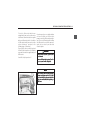
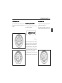
Please read this manual and follow the
instructions carefully.
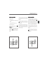
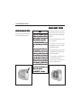
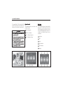
: This is the safety alert symbol used to
alert you to potential hazards including
injuries or damage to your vehicle or
other property. Obey all safety messages that follow this symbol.
Throughout this manual, you will find special
notations:
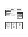
• Warning
CAUTION
CAUTION indicates a potentially
hazardous situation which, if not
avoided, may result in minor or moderate injuries, or damage to your
vehicle or other pr
oper
proper
opertty.
NOTE
NOTE indicates information which will
assist you with maintenance or other
instructions concerning your vehicle.
• Caution
• Note
WARNING
WARNING indicat
es a pot
entially haz
indicates
potentially
haz-ardous situation which, if not avoided,
could result in serious injury or death.
All information, illustrations, and specifications in this manual are based on the latest
product information available at the time of
publication.
We reserve the right to change specifications
or designs at any time without notice and
without incurring obligation.
This manual describes all options and features
available for this model. Certain descriptions,
including those for display and menu functions, may not apply to your vehicle due to
model variant, country specifications, special equipment or accessories.
Non-genuine parts and accessories have not
been examined or approved by our company.
We can certify neither the suitability nor the
safety of non-genuine parts and accessories
and are not liable for damage caused by their
use.
Important: Read Section 1 ("Seats and
Occupant Protection Systems") of this manual
fully and carefully before operating your
vehicle.
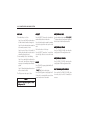
TABLE OF CCONTENT
ONTENT
S
ONTENTS
1. SE
ATS AND OC
CUP
ANT PR
OTE
CTION SY
STEMS ..............................................................................
SEA
OCCUP
CUPANT
PRO
TECTION
SYSTEMS
11-11
(Important information about safety belts, air bags, child seats and other safety features)
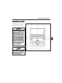
2. INSTRUMENTS AND CONTROLS .....................................................................................................
2-1
(Information about instruments, gauges and vehicle controls)
3. DRIVING YOUR VEHICLE ................................................................................................................
(Information about how to drive your vehicle under various conditions.)
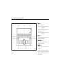
4. CLIMA
TE C
ONTR
OL AND A
UDIO SY
STEM .......................................................................................
CLIMATE
CONTR
ONTROL
AUDIO
SYSTEM
33-11
44-11
(How to operate your heating, ventilation, air conditioning and audio systems)
5. EMERGENCIES ...............................................................................................................................
55-11
(Important information about what to do if you have a problem while driving)
6. SERVICE AND VEHICLE CARE
CARE. ................................................................................................................
66-11
(Information about how to properly maintain your vehicle.)
7. VEHICLE MAINTENANCE ................................................................................................................
7-1
(Information about vehicle maintenance)
8. TE
CHNIC
AL INF
ORMA
TION ............................................................................................................
TECHNIC
CHNICAL
INFORMA
ORMATION
88-11
(Vehicle specifications, lubricant types and other useful information)
9. NA
VIG
ATION SY
STEM ....................................................................................................................
NAVIG
VIGA
SYSTEM
99-11
(How to operate navigation system)
10. INDEX ............................................................................................................................................
1010-11
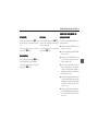
SEATS AND OCCUPANT PROTECTION SYSTEMS 1–1
1
S EEA
AT S AND OC
CUP
ANT
OCCUP
CUPANT
PR
OT EECTION
CTION SY
STEMS
SYSTEMS
RO
•
AL
WAYS WE
AR Y
OUR S
AFET
Y BEL
TS ................ 1-2
ALW
WEAR
YOUR
SAFET
AFETY
BELT
•
FR
ONT SE
ANT
S ................................. 1-6
AT OC
CUP
FRONT
SEA
ANTS
OCCUP
CUPANT
•
RE
AR SE
AT OC
CUP
ANT
S ................................... 1-6
REAR
SEA
OCCUP
CUPANT
ANTS
•
THIRD R
OW SE
ANT
S ......................... 1-6
AT OC
RO
CUPANT
ANTS
SEA
OCCUP
CUP
•
THREE POINT S
AFET
Y BEL
TS ............................ 1-6
SAFET
AFETY
BELT
•
SAFET
Y BEL
T PRETENSIONER ........................... 1-8
AFETY
BELT
•
SAFET
Y BEL
T HEIGHT ADJUST
MENT .................. 1-9
AFETY
BELT
ADJUSTMENT
•
PRE
GNANT W
OMEN AND S
AFET
Y BEL
TS ......... 110
PREGNANT
WOMEN
SAFET
AFETY
BELT
1-10
•
CHILD RESTRAINT ........................................... 110
1-10
•
LOWER ANCHOR AND TOP TETHER ANCHOR
FOR CHILD RESTRAINTS .................................. 112
1-12
•
HEAD RESTRAINTS .......................................... 119
1-19
•
FR
ONT SE
ATS ................................................. 1-20
FRONT
SEA
•
ELE
CTRIC SE
AT ............................................... 1-23
ELECTRIC
SEA
•
RE
AR SE
ATS ................................................... 1-24
REAR
SEA
•
SUPPLEMENT
AL RESTR
AINT SY
STEM
SUPPLEMENTAL
RESTRAINT
SYSTEM
(AIR BAG) ........................................................ 1-28
1–2 SEATS AND OCCUPANT PROTECTION SYSTEMS
A LLW
W A Y S W EEA
AR Y
OUR
YO
Y B E LLT
TS !
TY
SAFET
Occupant protection has been the focus of
much private and public research and
development for many years. The two vehicle
components which are incorporated into the
vehicle solely for the protection of the
occupants in vehicle accidents are the safety
belts provided at each seating position and the
supplemental restraint system, or air bags,
provided at the driver and front passenger
seat positions. The safety belts can protect you
and your passengers only if they are used. The
air bag is a supplemental protective device
that is more effective and safer as a
restraining device when the safety belts are
being used.
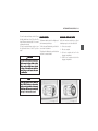
This vehicle has indicators as a reminder to
buckle the safety belts. (See “SAFETY BELT
WARNING LAMP” in the index for more
information.)
WHY WE
AR S
AFET
Y BEL
TS?
WEAR
SAFET
AFETY
BELT
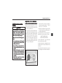
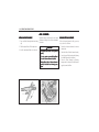
Safety belts are helpful for several distinct
reasons:
1) Safety belts attach the occupants to the
vehicle so that they will not be ejected
during an accident.
2) Safety belts attach the occupant to the
vehicle so that they can use the space
between their pre-crash seating position
and the front of the vehicle to slow down
to a stop more gradually, as their safety
belts stretch and the front end of the
vehicle absorbs the energy of the crash by
crumpling.
3) Safety belts keep the driver in his seat, so
that the driver might have a chance to
regain control in certain accident situations.
4) Safety belts keep occupants from being
catapulted into and injuring the driver and
other occupants.
WARNING
• Safety belts have been shown to be
the single most effective protection
against injury or death in a vehicular
accident!
• As the owner and driver of your
vehicle, you must make certain that
each occupant is properly wearing the
safety belt provided at the seating
position.
• Pregnant women, injured, and
physically impaired persons should
also wear safety belts. Like all other
occupants, they are more likely to
suffer serious injury or death, if they
do not do so.
• The best way to protect the feotus
is tto
o pr
ot
ect the mother
prot
otect
mother..
• Why safety belts work, how to wear
them, and how to adjust your seat
xplained in this
position pr
operly
properly
operly,, is eexplained
section. Read all of the information
provided and always observe these
instructions and warnings in order to
gain the full benefit of these safety
systems.
SEATS AND OCCUPANT PROTECTION SYSTEMS 1–3
WHY S
AFET
Y BEL
TS W
ORK!
SAFET
AFETY
BELT
WORK!
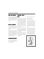
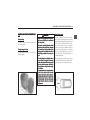
Safety belts cannot work unless they are worn
and worn properly.
Vehicle occupants are injured if the forces
applied to the body’s structures are greater
than the body can tolerate without being injured. If a person’s body is stopped abruptly,
the forces applied to the body will be high,
whereas if the body is slowed down gradually
over some distance, the forces will be much
lower. Thus, in order to protect an occupant
from injury in a crash, the idea is to give the
person as much time and distance as possible
in coming to a stop.
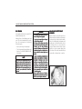
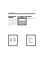
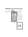
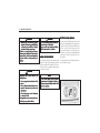
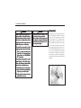
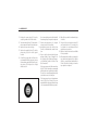
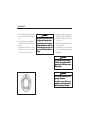
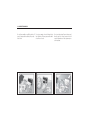
Imagine a person running at 15 miles per hour
(25 km/h) head first into a concrete wall.
Imagine a second person running at 15 miles
per hour into a wall covered by a 3-foot
(90 cm) thick deformable cushion. In the first
instance the person could be seriously injured
or even killed. In the second, the runner could
expect to walk away uninjured. Why? In the
first instance, the body hit the non-yielding
concrete surface and stopped immediately. All
of the energy the sprinter built up was absorbed by the structures of the body, not by
the non-yielding concrete surface. In the
second example, the body had exactly the
same amount of energy that had to be absorbed as in the first example, but it continued to move into the padding, giving the body
additional time and distance to slow down to
a complete stop as the padding absorbed the
sprinter’s energy by deforming.
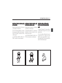
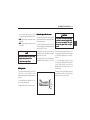
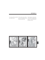
If a car crashes into a concrete wall at
30 miles per hour (50 km/h), the front
bumper of the car stops immediately, but the
passenger compartment stops more gradually
as the front structure of the vehicle crumples.
The belted occupant is held to the seat and
gains the advantage of the cushion provided
by the crumpling of the front of the vehicle
and the stretching of the safety belt webbing.
That belted occupant’s body slows down from
50 km/h (30 mph) to zero over a distance of
90-120 cm (3-4 feet). That belted occupant
also remains properly positioned so that, if the
air bag deploys in a frontal collision, the occupant might never strike any rigid structures
in the vehicle. The unbelted occupant receives
no such benefit. The unbelted person is not
attached to the vehicle and so that person
continues to travel at the vehicle’s pre-crash
speed of 30 miles per hour (50 km/h) until
striking a hard object at approximately
30 miles per hour (50 km/h) and stopping
abruptly. Even in a frontal collision in which
the air bag deploys, the unbelted front seat
occupant remains at greater risk of serious
injury or death than the properly restrained
front seat occupant. (See “SUPPLEMENTAL
RESTRAINT SYSTEM” in the index)
1–4 SEATS AND OCCUPANT PROTECTION SYSTEMS
WARNING
WARNING
SAFET
Y BEL
TS PR
OTE
AFETY
BELT
PRO
TECT
CT
Accident statistics show that drivers
and passengers properly wearing safety
belts have a lower risk of being injured
and a higher chance of surviving an accident. For this reason, wearing a safety
belt is legally required in most countries.
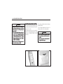
WE
ARING THE S
AFET
T
WEARING
SAFET
AFETY
BELT
Y BEL
All seats of your vehicle are equipped
with a three-point safety belt system
that is anchored at three locations.
Both front seats and outboard rear
seats’ belts are stored and locked by a
retractor mechanism. When set in its
normal emergency locking mode, the
three-point safety belt requires no
length adjustment and allows freedom
of movement when the vehicle moves
at constant speeds.
(Continued)
However in a sudden or strong stop, or
during heavy acceleration or deceleration, the safety belt will lock automatio rrestr
estr
ain the body
cally tto
estrain
body..
In order to gain the full benefit of a
safety belt, you must wear it correctly
and position yourself correctly within
your seat, as follows:
• Seatback upright (not reclined, to
keep you from “submarining” or slipping out from under the safety belt,
and injuring vulnerable body parts in
a crash.)
• Occupant sitting upright (not
slouched, to properly position the lap
and shoulder portions of the safety
belt for maximum restraint and minimum injury to soft and vulnerable
parts of your body in a crash)
• Safety belt latch plate and buckle securely fastened with a “click” (if the
safety belt is not securely latched, it
cannot provide any protection; pull on
the belt to make sure it is secure)
(Continued)
WARNING
• Lap portion of safety belt snug and
low on hips and pelvis (not abdomen
where the restraining belt could
cause serious injury in a crash – THIS
IS P
AR
TIC
UL
ARL
Y IMPOR
TANT FFOR
OR
PAR
ARTIC
TICUL
ULARL
ARLY
IMPORT
PREGNANT WOMEN)
• Shoulder portion of the safety belts
over your outside shoulder and snug
against the chest (not under an arm,
around your neck, over an inside
shoulder or behind your back, and not
loose with slack allowing excessive
forward movement and injury in a
crash)
• Only one occupant per one safety belt
(do not allow more than one person
in a safety belt; multiple people in a
single safety belt can exceed the
capacity of the safety belts and
people sharing a safety belt can
cause crushing and other injuries to
each other in a crash)
(Continued)
SEATS AND OCCUPANT PROTECTION SYSTEMS 1–5
WARNING
WARNING
• Children in secure child seats (in a
crash the forces are too great for an
adult to hold onto a child and the
adult will crush the child if they
share the same safety belt)
• No unbelted occupants (occupants
not wearing a safety belt are an injury threat to themselves and to
other occupants in the vehicle because in a crash they become a freeflying body that will strike other persons in their path)
• No twisted safety belts (twisted
safety belts will not move freely and
restrain properly and can cut into the
occupants rather than spread the
force, thus increasing the risk of injury and death)
• Lock doors (unlocked doors increase
the risk of injury and death from
external impacts and ejection in a
crash)
(Continued)
• Make periodic checks (while riding in
the vehicle, check from time to time
to be sure that the lap portion of the
belt is snugly across the hips and has
not ridden up around the waist and
that the shoulder portion is midway
over the shoulder and across the
chest; properly positioned belts allow
the stronger structures of the hips
and shoulders to absorb the forces of
the belt ag
ainst the body
against
body,, while improperly positioned belts may cause
neck injury or injury to the vulnerable organs in the abdominal area).
• No hard or breakable objects, between
safety belts and body parts (objects
such as ballpoint pens, glasses, etc.
in the occupant’s pocket or on the
clothes can cause injury in the event
of a collision)
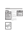
WARNING
If the safety belt goes over an armrest
(if so equipped), lap portion of the
safety belt could force the occupant’s
abdomen, not the pelvis, in a collision.
• Be sure that the safety belt goes
under the armrests.
Failure to follow this can result in injuries or even death in case of a collision.
1–6 SEATS AND OCCUPANT PROTECTION SYSTEMS
FR
O N T S EEA
A T O CCC
CUP
ANT
S
RO
PA
TS
Each front seat is equipped with adjustable
seat and seatback with height-adjustable head
restraint, three point lap-and-shoulder safety
belts, and a supplemental restraint system
(air bag).
R EEA
A R S EEA
A T O CCC
CUP
ANT
S
PA
TS
The rear seat is equipped with two outboard
seating positions and a centre seating position featuring three-point lap-and-shoulder
safety belts.
Each outboard seating positions are equipped
with child restraint lower anchors and the top
tether anchors located on the back of the rear
seatback. (See “LOWER ANCHOR AND TOP
TETHER ANCHOR FOR CHILD RESTRAINT” in
the index for more information)
THIRD R
O W S EEA
A T O CCCC U P
A N TTS
S
RO
PA
The third row seat is equipped with two
seating positions featuring three-point
lap-and-shoulder safety belts.
THREE-POINT SAFETY
B E LLT
TS
To help reduce the risk of personal injury in
collisions or sudden manoeuvres, your vehicle
is equipped with three-point safety belts. The
two front seats, the rear seats and the third
row seats are each equipped with three-point
safety belts. These safety belts are each anchored in three locations to restrain passengers who are properly positioned and wearing the safety belt.
A three-point safety belt set in the ELR
(Emergency Locking Retractor) mode requires
no length adjustment and allows the freedom
of body movement when the vehicle moves
at a constant speed.
However, in the event of a sudden or strong
stop, or during heavy acceleration or deceleration, the safety belt will lock automatically
to restrain the body.
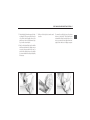
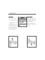
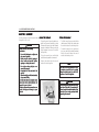
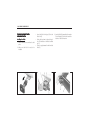
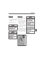
Always fasten your safety belts correctly:
1. Close and lock the doors.
2. Make sure seatback is upright.
3. Pick up the safety belt latch plate and use
it to pull the belt across your body. Make
sure the belt is not twisted. If the safety
belt locks as you are pulling it out, allow it
to rewind into the retractor. Pull the safety
belt out again to a comfortable and secure
length.
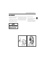
4. Position the shoulder belt midway over the
shoulder and across the chest. Never place
the shoulder belt across the neck. This
assures that in the case of a collision, the
belt applies force to the shoulder bones and
keeps the impact away from ribs or neck,
helping to avoid serious internal injuries.
SEATS AND OCCUPANT PROTECTION SYSTEMS 1–7
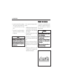
5. Wear the lap belt low and snug on the hips,
not the waist. This assures that in the case
of a collision, the belt applies force to the
pelvic bones and not the abdomen, helping to avoid serious injuries.
6. Push the latch plate firmly into the buckle
until the mechanism clicks. Make sure you
are using the proper buckle. Be sure to
position the release button on the buckle
so you can unbuckle the safety belt quickly
if necessary.
7. Pull up on the latch plate to make sure it
is secure.
To remove the safety belt, press the release
button on the buckle. The belt will retract
automatically. Guide the safety belt as it retracts to prevent the latch plate from damaging interior surfaces or injuring occupants.
1–8 SEATS AND OCCUPANT PROTECTION SYSTEMS
Maintain your safety belts:
1. Periodically inspect all safety belts, related
parts, and assemblies. Have these replaced
by a workshop if any safety belts or assemblies or related parts are damaged.
We recommend your authorised Chevrolet
repairer.
2. You must replace any safety belt or related
part that has been stretched or damaged
in an accident, even if the stretching or
damage is not obvious or visible. Stretched
belts and damaged parts do not perform
effectively. Replacement of safety belts
must be new.
3. We recommend replacing the entire safety
belt assembly after your vehicle has been
in a collision. If a trained specialist finds
that no safety belt damage has occurred
and that everything is in proper working
order, you need not make any replacement.
We recommend that you consult your
authorised Chevrolet repairer.
4. It is dangerous to operate your vehicle with
damaged safety belts or other parts.
SA F E T
Y BEL
TY
BELT
T
PRETENSIONER
Your vehicle is equipped with a safety belt
pretensioner system at the front seating positions. You can use the pretensioner safety
belts in the same manner as ordinary safety
belts.
The safety belt pretensioner system is activated based on crash severity. The crash sensors and the electronic controller of the air
bag system also control the safety belt
pretensioners.
The pretensioner is located around retractor
of each front safety belt. The pretensioner
tightens the safety belt so the belt fits the
occupant’s body more snugly in the event of
a frontal crash. The retractors will remain
locked after the pretensioners are activated.
Upon activation, some noise will occur and
some smoke may be released. These conditions are not harmful and do not indicate a
fire in the vehicle.
The driver and all passengers must be properly restrained by wearing safety belts at all
times, whether or not a pretensioner is
equipped at their seating position, to minimise
the risk of severe injury or death in the event
of a crash. Sit fully back in the seat; sit up
straight; do not lean forward or sideways.
Adjust the belt so the lap portion of the belt
is worn low across the pelvis, not across the
waist.
Please note that the pretensioners will activate in severe frontal collisions and side impacts. They are not designed to activate in
rear impacts or minor frontal collisions. The
pretensioners can be activated only once. If
the pretensioners are activated, have the
pretensioner system serviced by a workshop
as soon as possible. We recommend your
authorised Chevrolet repairer.
SEATS AND OCCUPANT PROTECTION SYSTEMS 1–9
If the air bag warning lamp on the instrument
cluster does not blink or come on briefly when
the ignition switch is turned to the “ON”
position, stays on for more than 10 seconds,
or comes on while driving, the pretensioner
system or the air bag system may not work
properly. Have both systems inspected by a
workshop as soon as possible. We recommend your authorised Chevrolet repairer.
Service on or around the pretensioner system
components or wiring must be performed only
by a specially trained workshop. We recommend your authorised Chevrolet repairer.
Improper service could result in unintended
activation of pretensioners or could render the
pretensioner inoperative. Either of these two
conditions may result in personal injury.
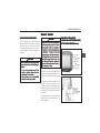
SAFET
Y B E LLT
TY
T HEIGHT
ADJUSTMENT
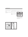
Before you begin to drive, move the safety
belt height adjuster to the height that is right
for you.
Adjust the height so that the shoulder portion
of the belt is centred on your shoulder. The
belt should be away from your face and neck,
but not falling off your shoulder. Incorrect
positioning of the shoulder belt can reduce
the effectiveness of the safety belt.
WARNING
Incorrect adjustment of the safety belt
height could reduce the effectiveness
of the safety belt in a crash.
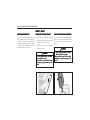
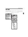
To move it up or down, squeeze the release
buttons together and move the height
adjuster to the desired position. You can move
the height adjuster up just by raising it up
without squeezing the buttons.
1–10 SEATS AND OCCUPANT PROTECTION SYSTEMS
WARNING
Never drive with an improperly
positioned saf
et
o help avoid
safet
etyy belt
belt.. T
To
injuries, always observe the following
precautions:
• Adjust the safety belt height before
driving.
• Wear the shoulder belt midway
acr
oss the shoulder
across
shoulder..
• Lock the safety belt anchor in
position.
Failure to follow these precautions can
result in injuries or even death in case
of a collision.
PREGNANT WOMEN AND
Y B E LLT
TS
TY
SAFET
Safety belts work for everyone, including pregnant women.
Like all occupants, pregnant women are more
likely to be seriously injured if they do not
wear safety belts. In addition, when a safety
belt is worn properly, it is more likely that the
unborn child will be safe in a crash.
To provide maximum protection, a pregnant
woman should wear a three-point safety belt.
She should wear the lap portion of the belt
as low as possible throughout her pregnancy.
CHILD RESTRAINT
WARNING
Child safety restraints are available in
a wide range of sizes and configurations. Due to the shape and dimensions
of your vehicle’s interior and seats, not
all child safety restraints will fit in your
vehicle.
It is your responsibility to ensure that
the child safety restraint you are
installing fits properly and can be
adequately attached to the vehicle with
the safety belts and the child safety
restraint anchors.
A child safety restraint that is not the
correct size for the vehicle or the child,
or a child safety restraint that is
improperly attached to your vehicle can
lead to serious personal injury to the
child and other passengers in the
vehicle in the event of a collision.
SEATS AND OCCUPANT PROTECTION SYSTEMS 1–11
Once you have selected an appropriate infant
or child restraint, read and carefully follow the
manufacturer’s instructions for installing and
using the system. The child restraint system
should be appropriate for your child’s age,
height and weight; and it should fit properly
and securely in the vehicle. There are different
kinds of restraint systems that are available
for all sizes of children until they reach a
height and weight at which they can safely
use the vehicle’s safety belt system.
WARNING
Accident statistics show that children are
safer in accidents when they are restrained
in the rear seat rather than the front seat
of the vehicle.
Children who have outgrown their child restraint system should sit in the rear seat, restrained by the safety belt that is fastened
properly, making sure that the shoulder portion is adjusted to be as far away from the
neck as possible and that the lap portion is
low across the hips. Check the belt position
from time to time to verify that it is safely
positioned.
If the child must sit in a front seat, make certain that the shoulder belt does not lie across
the child’s face or neck. If it does, move the
child closer to the centre of the vehicle so that
the safety belt is on the child’s shoulder.
sal
Your vehicle is designed tto
o fit univer
universal
child restraint seat only to the each rear
outboard seating positions.
Never let the child stand or kneel on the seat,
or in the cargo areas, while your vehicle is
moving.
• Do not install universal child restraint
at
o the fr
ont passeng
er
se
at tto
passenger
er’’s se
seat
seat
front
and/or rear centre seating position.
When the child seat is not in use, secure the
seat with the vehicle’s safety belt or remove
it from the vehicle.
1–12 SEATS AND OCCUPANT PROTECTION SYSTEMS
WARNING
• Never hold a baby in your arms while
riding in a vehicle. Be sure to secure
infants and small children in
restraints approved for their use.
• During a crash, a baby will become so
heavy you can’t hold it. For example,
in a crash at only 40 km/h (25 mph),
a 12-lb (5.5 kg) baby will become a
240-lb ((110
110 kkg
g ) ffor
or
ainst your
orcc e ag
against
arms.
• Failing to secure infants and small
children in restraints approved for
their use can result in injury during
a collision, or even death.
• According to accident statistics,
children are safer when properly
restrained in the rear seats than in
a front seat.
• Do not install any child restraint in
the fr
ont passeng
er
at if your
front
passenger
er’’s se
seat
vehicle is equipped with side air bag.
See “SIDE AIR BAGS” in the index for
more information.
(Continued)
WARNING
(Continued)
• Extreme Hazard! Do not use a
rearward facing child restraint on a
seat protected by an air bag in front
of it! Always secure a rear-facing
child restraint in the rear seat.
LOW
E R ANCHOR AND TOP
WE
TETHER ANCHOR FOR
CHILD RESTRAINTS
In the past, child restraints have been
attached to a vehicle’s seat by safety belts.
As a result, child restraints were often
installed incorrectly or too loosely to
adequately protect your child.
We now equip your vehicle with lower anchors
and top tether anchors at the two rear outboard seating positions, allowing child restraints to be attached directly to the body of
the vehicle.
SEATS AND OCCUPANT PROTECTION SYSTEMS 1–13
To install a child restraint which comes
equipped with lower and top tether anchor
attachments, follow the instructions supplied
with your child restraint and the “Installation
of child restraints with lower and top tether
anchor attachments” procedure on the
following pages of this manual.
Please take the time to carefully read and
follow all of the instructions on the following
pages and the instructions supplied with your
child restraint.
Your child’s safety depends on it!
If you have questions, or any doubts whether
you have installed your child restraint
properly, contact the child restraint manufacturer. If you are still having trouble installing
the child restraint in your vehicle, we recommend that you consult your authorised
Chevrolet repairer.
CAUTION
Unused child restraint system could
move forward.
Remove child restraint system if not in
use, or secure it with safety belt.
NOTE
Since a safety belt or child restraint
system can become very hot if it is left
in a closed vehicle
vehicle,, be sure and check the
seat cover and buckles before placing a
child there.
1–14 SEATS AND OCCUPANT PROTECTION SYSTEMS
CHILD RESTR
AINT INST
ALL
ATION LLOC
OC
ATIONS
RESTRAINT
INSTALL
ALLA
OCA
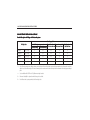
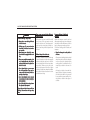
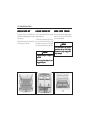
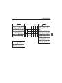
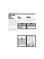
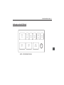
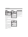
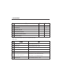
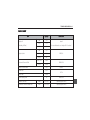
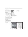
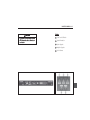
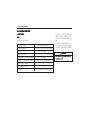
Permissible options for fitting a child restraint system
Seating positions
Weight class
On front passenger seat
On outboard seats On centre seat in
activated airbag deactivated airbag in the second row the second row
On the seats in
the third row
Group 0
up to 10 kg
X
U1
U+
X
X
Group 0+
up to 13 kg
X
U1
U+
X
X
Group I
9 to 18 kg
X
U1
U+
X
X
Group II
15 to 25 kg
X
X
U
X
X
Group III
22 to 36 kg
X
X
U
X
X
1 = Only if front passenger seat airbag systems are deactivated. If the child restraint system is being secured using a three-point seat belt,
adjust the seat backrest angle to the most forward position and ensure that vehicle safety belt runs forwards from the upper anchorage
point.
+ = Seat available with ISOFIX and Top-Tether mounting brackets.
U = Universal suitability in conjunction with three-point seat belt
X = No child restraint system permitted in this weight class
SEATS AND OCCUPANT PROTECTION SYSTEMS 1–15
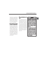
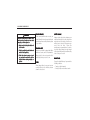
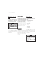
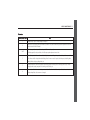
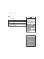
PERMISSIBLE OPTIONS FOR FITTING AN ISOFIX CHILD RESTRAINT SYSTEM
Seating positions
Weight class
Group 0
Group 0+
Group I
IL
up to 10 kg
up to 13 kg
9 to 18 kg
Size class
Fixture
On front
passenger seat
On outboard
seats in the
second row
On centre seat
On the seats in
in the second
the third row
row
E
ISO/R1
X
IL
X
X
E
ISO/R1
X
IL
X
X
D
ISO/R2
X
IL
X
X
C
ISO/R3
X
IL
X
X
D
ISO/R2
X
IL
X
X
C
ISO/R3
X
IL
X
X
B
ISO/F2
X
IL, IUF
X
X
B1
ISO/F2X
X
IL, IUF
X
X
A
ISO/F3
X
IL, IUF
X
X
= Suitable for particular ISOFIX restraint systems of the 'specific-vehicle', 'restricted' or 'semi-universal' categories.
The ISOFIX restraint system must be approved for the specific vehicle type.
IUF = Suitable for ISOFIX forward-facing child restraint systems of universal category approved for use in this mass group.
X
= No ISOFIX child restraint system approved in this weight class.
1–16 SEATS AND OCCUPANT PROTECTION SYSTEMS
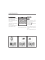
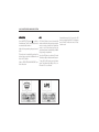
ISOFIX size class and seat device
A – ISO/F3
= Forward-facing child restraint system for children of maximum size in the weight class 9 to 18 kg.
B – ISO/F2
= Forward-facing child restraint system for smaller children in the weight class 9 to 18 kg.
B1 – ISO/F2X = Forward-facing child restraint system for smaller children in the weight class 9 to 18 kg.
C – ISO/R3
= Rear-facing child restraint system for children of maximum size in the weight class up to 13 kg.
D – ISO/R2
= Rear-facing child restraint system for smaller children in the weight class up to 13 kg.
E – ISO/R1
= Rear-facing child restraint system for young children in the weight class up to 13 kg.
SEATS AND OCCUPANT PROTECTION SYSTEMS 1–17
WARNING
Use all lower and top tether anchors for
their designed purpose only
only..
Lower and top tether anchors are
designed only to hold child restraints
which come equipped with lower and top
anchor attachments.
• Do not use lower and top tether
anchors to hold adult safety belts,
harnesses, or other items of
equipment in your vehicle.
Using lower and top tether anchors to
hold adult safety belts, harnesses, or
other items or equipment in your vehicle
will not provide adequate protection in
the case of a collision and could result
in injuries or even death.
WARNING
Child restraint system placed in the
front seat could cause serious injury or
death.
Never install a rear-facing child
restraint in the front seat of a vehicle
equipped with a front passenger air
bag.
A child in a rear-facing child restraint
installed in the front seat can be
seriously injured if the front passenger
air bag inflates.
Secure a rear-facing child restraint in
the rear seat.
A front-facing child restraint should be
secured in the rear seat whenever
possible. If installed in the front
passenger seat, adjust the seat as far
back as it will go.
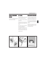
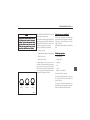
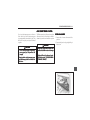
Installation of child restraints with lower
and top tether anchor attachments
1. Select one of the rear outboard seating
positions for installation of the child
restraint.
1–18 SEATS AND OCCUPANT PROTECTION SYSTEMS
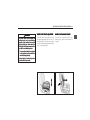
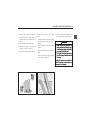
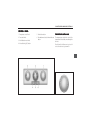
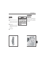
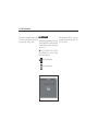
2. Locate the two lower anchor positions. The
location of each lower anchor is identified
with a circular marking on the lower edge
of the rear seatback.
4. Place the child restraint on the seat over
the two lower anchors and attach it to the
anchors following the instructions supplied
with the child restraint.
3. Make sure there are no foreign objects
around lower anchors, including safety belt
buckles or safety belts. Foreign objects can
interfere with the proper latching of the
child restraint to the anchors.
5. Adjust and tighten the child restraint
according to the instructions supplied with
the child restraint.
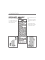
6. Attach the clip on the child restraint’s
tether strap to the top tether anchor,
making sure to remove any twists in the
tether strap.
If the position you are using has an
adjustable head restraint and you are using
a dual tether, route the tether around the
head restraint.
If the position you are using has an adjustable head restraint and you are using a
single tether, raise the head restraint and
route the tether under the head restraint
and in between the head restraint posts.
WARNING
Make sure the clip on the child
restraint’s tether strap is properly
att
ached to the ttop
op ttether
ether anchor
anchor..
attached
Incorrect attachment could render the
tether strap and top tether anchor
ineffective.
7. Tighten the child restraint’s tether strap
according to the instructions supplied with
the child restraint.
8. Push and pull the child restraint in different
directions after installation to be sure it is
secure.
SEATS AND OCCUPANT PROTECTION SYSTEMS 1–19
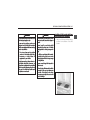
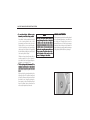
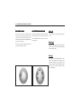
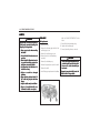
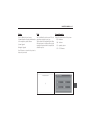
HEAD
RESTRAINTS
Head restraints are designed to reduce the risk
of neck injuries in case of a collision.
For maximum protection, slide the head
restraint up or down so the top of the
restraint is level with the top of your ears.
WARNING
Removed or improperly adjusted head
restraints can result in serious head and
neck injuries in case of a collision.
Pull up the head restraints in order to adjust
the position upward. Push down the head
restraints while pressing the release button
in order to adjust the position downward.
To tilt the front head restraints,
1. Place it in its upright position by pushing
it forward fully and releasing it.
2. Push the head restraint forward carefully
until it is adjusted to the desired position.
1–20 SEATS AND OCCUPANT PROTECTION SYSTEMS
FR
O N T S EEA
AT S
RO
ACTIVE HEAD RESTRAINTS
FR
ONT SE
AT SLIDE ADJUST
MENT
FRONT
SEA
ADJUSTMENT
FR
ONT SE
AT RE
CLINING ADJUST
MENT
FRONT
SEA
RECLINING
ADJUSTMENT
In the event of a rear-end impact, the active
head restraints at front seats automatically
tilt forwards. The head is more effectively
supported by the head restraint and the risk
of injuries caused by hyperextension in the
cervical vertebrae area is reduced.
To move the front seat forward or backward:
To tilt seatback forward or backward, lift the
lever on the outside of the seat cushion until
the seatback is adjusted to the desired
position.
1. Pull up and hold the lever located under
the front side of the front seat.
2. Slide the seat to the desired position.
3. Release the lever.
WARNING
• Do not adjust the driver
at while
driver’’s se
seat
the vehicle is moving.
Driver could lose control of the vehicle
and injury or property damage could
result.
WARNING
• Do not adjust the driver
atback
driver’’s se
seatback
while the vehicle is moving.
Driver could lose control of the vehicle
and injury or property damage could
result.
SEATS AND OCCUPANT PROTECTION SYSTEMS 1–21
WARNING
If a crash occurs, front occupants in
reclined seats can lose restraining
benefits of the seatback and safety
belts by sliding out from under the
safety belt or by being thrown into the
seat belt in an awkward position.
• Do not position either front seatback
in the reclined position while the
vehicle is being operated.
Serious injuries, death and ejection
from the vehicle can result.
DRIVER
AT HEIGHT ADJUST
MENT
DRIVER’’S SE
SEA
ADJUSTMENT
DRIVER
AT LLUMBAR
UMBAR SUPPOR
T
DRIVER’’S SE
SEA
SUPPORT
To raise the driver’s seat cushion, move the
lever upward repeatedly until the seat is at
the desired height. To lower the seat cushion,
move the lever downward repeatedly until the
seat is at the desired height.
To increase or decrease the driver’s seat
lumbar support, move the lever forward or
rearward.
1–22 SEATS AND OCCUPANT PROTECTION SYSTEMS
PASSENGER
AT FFOLDING
OLDING
ASSENGER’’ S SE
SEA
CAUTION
If you fold the seatback forward to carry
longer objects, such as skis, be sure any
such cargo is not near an airbag. In a
crash, an inflating airbag might force
that object toward a person. This could
cause severe injury or even death. Secure objects away from the area in which
an airbag would inflate.
CAUTION
Things you put on this seatback can
strike and injure people in a sudden stop
or turn, or in a crash. Remove or secure
all items before driving
driving..
To fold the passenger’s seatback, do the
following:
To raise the passenger’s seatback, do the
following:
1. Lower the head restraint all the way.
1. Lift the seatback and push to original position.
2. Pull up and hold the lever under the front
of the seat to slide the seat as far back as
it will go and release the lever.
3. Lift the recliner lever, located on the outboard side of the seat, up fully and fold
the seatback forward until it stops in the
folded position.
2. Latch the seatback into place by pushing
on the top of the seatback.
3. Pull the seatback forward again to make
sure the seatback is properly latched.
CAUTION
If the seatback is not locked, it could
move forward in a sudden stop or crash.
That could cause injury to the person
sitting there. Always push and pull on
the seatback to be sure it is locked.
SEATS AND OCCUPANT PROTECTION SYSTEMS 1–23
E L EEC
C T R I C S EEA
AT
( D R I V E R ' S S EEA
A T O N LLY
Y)
SE
AT SLIDE ADJUST
MENT
SEA
ADJUSTMENT
To move the seat forward or backward, move
and hold the switch forward or backward.
When the seat reaches the desired position,
release the switch.
WARNING
• Do not adjust the driver
at while
driver’’s se
seat
the vehicle is moving.
Driver could lose control of the vehicle
and injury or property damage could
result.
SE
AT HEIGHT ADJUST
MENT
SEA
ADJUSTMENT
SE
AT RE
CLINING ADJUST
MENT
SEA
RECLINING
ADJUSTMENT
To adjust the height of the front or rear part
of the seat cushion, push the front or rear part
of the switch up or down.
To tilt seatback forward or backward, move
and hold the upper part of the switch forward
or backward.
When the seatback reaches the desired
position, release the switch.
When the seatback reaches the desired
position, release the switch.
WARNING
• Do not adjust the driver
at while
driver’’s se
seat
the vehicle is moving.
Driver could lose control of the vehicle
and injury or property damage could
result.
WARNING
• Do not adjust the driver
atback
driver’’s se
seatback
while the vehicle is moving.
Driver could lose control of the vehicle
and injury or property damage could
result.
1–24 SEATS AND OCCUPANT PROTECTION SYSTEMS
R EEA
A R S EEA
AT S
WARNING
If a crash occurs, front occupants in
reclined seats can lose restraining
benefits of the seatback and safety
belts by sliding out from under the
safety belt or by being thrown into the
seat belt in an awkward position.
• Do not position either front seatback
in the reclined position while the
vehicle is being operated.
Serious injuries, death and ejection
from the vehicle can result.
FOLDING RE
AR SE
ATBA
CK
REAR
SEA
TBACK
WARNING
• Do not stack luggage or other cargo
higher than the front seats.
• Do not allow passengers to sit on the
folded seatbacks while the vehicle is
in motion.
a tte
e ar
ea s
• Your vehicle has separ
separa
are
designed specifically for carrying
cargo or passengers.
• Unrestrained luggage or passengers
on a folded seatback can be thrown
about within or ejected from the
vehicle in a sudden stop or accident.
Serious injuries or death can result.
CAUTION
Folding a rear seat with the safety belts
still fastened may cause damage to the
seat or the safety belts. Always
unbuckle the safety belts and return
them to their normal stowed position
before ffolding
olding a rear seat.
SEATS AND OCCUPANT PROTECTION SYSTEMS 1–25
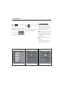
To fold down the rear seatbacks separately:
1. Ensure all three of the safety belts are
unbuckled and the front seatbacks are not
reclined.
To return a rear seatback to its original
position:
2. Push the head restraints fully down.
1. Hook the safety belts to the retaining guide
to make sure the safety belts are not
pinched.
3. Lift the lever located on the top of the
seatback to release the seatback.
2. Lift the rear seatback and push to original
position.
4. Fold the rear seatback forward and down.
3. Unhook the safety belts from the retaining
guide.
4. Latch the seatback into place by pushing
on the top of the seatback.
5. Pull the seatback forward again to make
sure the seatback is properly latched.
WARNING
• Ensure that the rear seatbacks are
all the way back and locked in position before operating the vehicle with
passengers in the back seat.
• Do not pull the release levers on the
top of the seatback while the vehicle
is moving.
Pulling the release levers while the
vehicle is moving can cause injuries or
damage to the occupants.
1–26 SEATS AND OCCUPANT PROTECTION SYSTEMS
RE
AR SE
AT RE
CLINING ADJUST
MENT
REAR
SEA
RECLINING
ADJUSTMENT
The rear seatbacks can be partially reclined.
To tilt the seatbacks, lift the lever on top of
the rear seatback until the seatback is
adjusted to the desired position.
DOUBLE F
OLDING RE
AR SE
AT
FOLDING
REAR
SEA
(7 SE
ATER ONL
Y)
SEA
ONLY
WARNING
• Do not stack luggage or other cargo
higher than the front seats.
• Do not allow passengers to sit on rear
compartment when the rear seats
are folded forward.
• Unrestrained luggage or passengers
in rear compartment can be thrown
about within or ejected from the
vehicle in a sudden stop or accident.
• Folding a rear seat with the safety
belts still fastened may cause
damage to the seat or the safety
belts. Always unbuckle the safety
belts and return them to their normal stowed position before folding a
rear seat.
• When double folding or unfolding,
make sure the safety belt buckles are
not pinched by the seat.
Serious injuries or death can result.
For third row seating entry or exit, do the
following:
1. Ensure all three of the safety belts are
unbuckled and the front seatbacks are not
reclined.
2. Push the head restraints fully down.
3. Pull the lever forward on the outside of
the seatback and fold the seatback.
SEATS AND OCCUPANT PROTECTION SYSTEMS 1–27
4. The seat will tumble forward automatically
and air-pressurised support rods will hold
the seats folded.
To return the rear seat to its original position:
1. Hook the safety belts to the retaining guide
to make sure the safety belts are not
pinched.
2. Guide the rear seat cushion down.
3. Lock the rear seat cushion on the floor.
Make sure that the rear seat cushion is
securely latched by pulling it up and down.
4. Return the rear seatback to its original
position. Make sure that the seatback is
securely latched by pulling it back and
forth.
5. Unhook the safety belts from the retaining
guide.
WARNING
• Do not place the legs or other body
parts on the floor under rear seat
cushion when guiding the rear seat
cushion down.
Serious injuries can result.
CAUTION
Do not pull the lever when the seatback
is folded. This operation can cause
damage to the lever or related parts.
1–28 SEATS AND OCCUPANT PROTECTION SYSTEMS
FOLDING THE THIRD R
OW SE
AT
RO
SEA
To return the rear seat to its original position:
To fold down the third row seatbacks:
1. Raise the seatback to its original position.
Make sure that the seatback is securely
latched by pulling it back and forth.
1. Ensure the safety belts are unbuckled.
2. Lift the lever on the back of the each
seatback.
3. Push the seatback forward and fold the
seatback.
2. Push the head restraint backward to its
original position.
SUPPLEMENT
AL RESTR
AINT
SUPPLEMENTAL
RESTRA
SYSTEM (AIR BAG)
Your vehicle is equipped with an air bag
supplemental restraint system (SRS) designed to protect properly seated and restrained seat occupants. Both the driver and
front passenger seating positions are
equipped with driver and passenger air bags
and side air bags, in addition to three-point
safety belts and other safety features. Your
vehicle has also curtain air bags. Curtain air
bags are available for the driver and the passenger seated directly behind the driver and
for the right front passenger and the passenger seated directly behind that passenger.
Each air bag is specially packed in a module,
from which the air bag is designed to inflate
and deploy at extremely high speed and force
in the event your vehicle is involved in certain
types of collisions which pose a high risk of
serious injury or death to the driver and
passengers.
SEATS AND OCCUPANT PROTECTION SYSTEMS 1–29
DRIVER
ONT P
ASSENGER
DRIVER’’S AND FR
FRONT
PASSENGER
ASSENGER’’S AIR
BAG
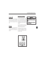
Driver
Driver’’s air bag
The driver’s air bag is located in the centre of
the steering wheel.
Fr
ont passeng
er
Front
passenger
er’’s air bag
The passenger’s air bag is located in the
instrument panel.
WARNING
Air bags are only a supplemental restraint,
and are most effective in combination
with safety belts.
All occupants, including the driver
driver,, should
always wear their safety belts, whether
or not an air bag is also provided at their
seating position, to minimise the risk of
severe injury or death in the event of a
crash.
• Frontal air bags do not deploy in side or
rear collisions. Occupants not wearing
their safety belts will not be protected
by any restraint system, resulting in
severe injuries or death in these types
of collisions.
• Occupants who are not properly wearing
their safety belts may be thrown
forward by braking before impact,
placing their bodies near or against the
air bag modules. This can cause severe
injury from the force of an air bag’s
deployment.
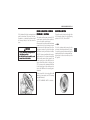
How air bags work
Air bags are designed to keep your head, neck,
and chest from slamming into the instrument
panel, steering wheel or windscreen in a front-end
crash. They are not designed to inflate in rearend or rollover crashes or in most side-impact
crashes. Your air bags are designed to deploy in
crashes that are equivalent to, or exceed the
force of a vehicle travelling at a speed of
15 to 23 km/h (9.3 ~ 14.3 mph) crashing into a
solid immovable wall.
The air bag system activates during a severe
collision which is either frontal or when the impact angle is up to 30° from straight ahead.
1–30 SEATS AND OCCUPANT PROTECTION SYSTEMS
This crash severity level at which the air bag
will deploy was selected to assure inflation of
air bags in our vehicles at or below the crash
severity at which a statistical risk of death
begins for frontal collisions.
In the real world, cars rarely crash squarely
into immovable walls; air bags most often
deploy when a vehicle collides with another
vehicle. The actual speed at which the air bags
will inflate may be higher in the real world,
because real-world accidents usually involve
more complicated multi-vehicle impacts,
angled impacts, and incomplete frontal impacts (e.g. sideswipes), and because the object struck is usually not immovable.
NOTE
An air bag can also inflate in moderate
to severe non-collision situations (e.g.,
slamming the undercarriage or other
solid component of the vehicle in a dip
in the driving surface) where the crash
sensors generate a signal equivalent to
a crash into a solid immovable barrier at
15 to 23 km/h (9.3 ~ 14.3 mph).
Air bags inflate when a sensor detects a frontend crash of a severity sufficient for air bag
deployment. The crash sensor sends an electric signal to initiate the air bag’s inflation.
A propellant is ignited which rapidly burns inside the air bag module, producing enough
inert gas to fully inflate the air bag. Within
0.045 seconds of the crash detection, the pressure of the inflating air bag splits open the
plastic trim covering on the module, which is
scored on the inside surface to allow the trim
of the steering wheel hub or passenger-side
instrument panel to split open under force.
The air bag fully inflates to create a surface
that can catch the forward movement of the
front occupant’s head and upper torso. As the
occupant comes into contact with the air bag,
the gas in the bag empties through holes at
the base of the bag to soak up the force from
the occupant’s forward movement.
SEATS AND OCCUPANT PROTECTION SYSTEMS 1–31
NOTE
Air bags cannot smother you and they
don’t restrict your movement. Air bags
have vents, so they deflate immediately
after cushioning you.
The entire process, from initial contact
through the air bag’s inflation and deflation,
occurs within 0.2 seconds, faster than the
blink of an eye. Because the collision is over
in a fraction of a second, and vehicles involved
in an accident usually come to the final point
of rest only one or two seconds after initial
contact, the supplemental restraint system
must sense the crash and cause the air bags
to deploy nearly instantaneously to protect
the vehicle’s occupants.
SIDE AIR BAGS
The side air bag modules are located in the
outboard side of the front seatbacks.
WARNING
Air bags are only a supplemental restraint, and are most effective in combination with safety belts.
All occupants, including the driver
driver,,
should always wear their safety belts
whether or not an air bag is also provided at their seating position, to
minimise the risk of severe injury or
death in the event of a crash.
(Continued)
WARNING
(Continued)
• Do not place objects on or near the
side air bag modules in the outboard
side of each front seats. They can
become projectiles during inflation,
causing se
ver
e injur
sever
vere
injuryy.
• Do not install accessory seat covers
on the front seats. The deployment
of the side air bags can be obstructed
o serious injur
in a ccollision
ollision le
injuryy.
leading
ading tto
• Do not lean your body part or head
on the door
door.. The side air bag can hit
the occupants with a considerable
force when it deploys in a collision
o serious injur
le
ading tto
leading
injuryy.
• Do not install any child restraint in
at if your
the fr
ont passeng
er
seat
front
passenger
er’’s se
vehicle is equipped with the side air
bag.
Failure to follow these precautions can
result in serious injury or even death.
1–32 SEATS AND OCCUPANT PROTECTION SYSTEMS
How the side air bags work
Side air bags are designed to keep your thorax from slamming into the front door and
window in a lateral crash.
WARNING
The side air bags inflate when a sensor detects a lateral crash of a severity sufficient
for the side air bag deployment.
Children who are seated in close
proximity to a side air bag may be at risk
of serious or fatal injury if the air bag
deploys, especially if the child’s head,
neck, or chest is close to the air bag at
the time of deployment.
Your side air bags are designed to deploy in
lateral collisions that are equivalent to, or
exceed the force of a deformable moving
barrier travelling at a speed of 15 to 25 km/
h (9.3 ~ 15.5 mph) crashing into a vehicle.
• Never let your child lean on the door
or close to the side air bag module.
• The safest place in the vehicle for
your properly seated and restrained
child is the back seat.
The fact that your vehicle was involved in a
crash and the side air bags did not inflate
does not necessarily mean that there is something wrong with your side air bags. Side air
bags are designed to inflate in a side collision, not in front-end, rear-end, or rollover
crashes if they don’t produce sufficient lateral impact for the deployment of the side
air bags.
CUR
TAIN AIR BA
GS
CURT
BAGS
The curtain air bags are located in the ceiling
above the side windows. They are designed
to help protect the heads of the front seat
occupants and the rear outboard seat occupants in certain side impact collisions.
SEATS AND OCCUPANT PROTECTION SYSTEMS 1–33
The curtain air bags are designed to deploy
only during certain side impact collisions,
depending on the crash severity, angle, speed
and impact. They are not designed to deploy
in all side impact situations, collisions from
the front or rear of the vehicle or in most
rollover situations.
The curtain air bag system will be triggered
together with the side air bag system.
WARNING
Curtain air bags are designed to inflate
in moderate to severe crashes where
something hits the side of your vehicle.
They are not designed to inflate in
frontal, in rollover or in rear crashes.
Everyone in your vehicle should wear a
safety belt properly — whether or not
there is an air bag for that person.
WARNING
Never secure anything to the roof of
your vehicle by routing the rope or
tiedown through any door or window
opening. If you do, the path of an
inflating curtain air bag will be blocked.
The path of an inflating air bag must
be kkept
ept cle
ar
clear
ar..
AFTER THE AIR BAG DEPLOYS
After the air bag deflates, you may notice a
burning smell, smoke, and white powder in
the interior of the vehicle. This is normal. The
burning smell is from the propellant that was
ignited to inflate the airbag. The white powder
is cornstarch or talcum or sodium compounds
which lubricate the air bag to reduce friction
on the air bag during storage and inflation.
Although they may cause some skin or eye
irritation, these substances are not toxic.
NOTE
Your vehicle has a ffe
e atur
e that may
ature
automatically unlock the doors and turn
the hazard warning flashers on when
the airbags inflate.
1–34 SEATS AND OCCUPANT PROTECTION SYSTEMS
SRS SERVICING
Your Supplemental Restraint System(SRS) is
virtually maintenance free.
However, if any of the following occurs, have
your SRS serviced immediately by a workshop. We recommend your authorised
Chevrolet repairer.
• Any of your air bags have deployed.
• The air bag warning lamp indicates malfunction. See “AIR BAG WARNING LAMP”
in the index.
NOTE
If your vehicle is equipped with side air
bags, the front seat assembly must be
replaced after the side air bag has been
deployed. Consult a workshop for more
information. We recommend that you
consult your authorised Chevrolet
repair
er
epairer
er..
WARNING
• Do not drive your vehicle after one or
more air bags have deployed.
er
• Do not tr
o rrepair
epair
tryy tto
epair,, alt
alter
er,, or dispose
of the air bag your
self
yourself
self..
• Air bags are installed under high
pressure with sophisticated crash
sensing and air bag inflating
systems. Allowing an untrained and
unauthorised person to handle an air
bag can lead to serious injuries and
death.
• Contact a workshop immediately if
either of your vehicle’s air bag has
deployed, if damage occurs to your
vehicle at or near either of the air bag
modules, or if you believe for any
reason that the operating condition
of either air bag has been impaired.
We recommend your authorised
Che
vr
olet rrepair
epair
er
Chevr
vrolet
epairer
er..
Driving a vehicle after an air bag has
deployed without authorised service can
result in severe injuries and death.
HOW AIR BAGS PROTECT FRONT
OC
CUP
ANT
S
ANTS
OCCUP
CUPANT
Vehicle occupants are usually injured in a
collision because their bodies are thrown into
a stationary object, either inside the vehicle,
such as the steering wheel, instrument panel
or windscreen, or outside the vehicle, such as
the driving surface or a tree, when the
occupant is thrown from the vehicle. Severe
injuries also occur by occupants being jolted
by the forces of the crash, even without body
contact with a stationary object or surface.
SEATS AND OCCUPANT PROTECTION SYSTEMS 1–35
All of these injuries are caused by the force
created by the collision as the vehicle is
brought to a sudden stop. The time and
distance which a vehicle is allowed in slowing
or stopping in great part determines the
severity of a collision’s effect on vehicle
occupants. For example, when a vehicle brakes
to a stop at a red light, the occupant’s bodies
are forced forward. This is because both the
vehicle and its occupants are initially travelling
at the same speed. The brakes slow the
vehicle, and the occupants continue to move
forward somewhat inside the vehicle.
However, properly positioned and restrained
occupants are rarely injured when a vehicle
comes to a stop by even sudden and hard
braking. This is because even hard braking
allows a comparatively long time and distance
for the vehicle to stop. The safety belts and
the occupants’ strength are generally
sufficient to safely counteract the force of a
braking stop.
In a crash, a vehicle may go from highway
speed to a full stop in a fraction of a second
and in a distance of less than one foot. This
extremely short stopping time and distance
greatly increases the force placed upon the
occupants. No person has the strength or
reflexes to counteract this force. Even
occupants properly positioned and wearing
their safety belts will find their head, upper
torso, arms, and hips thrown forward at the
speed the vehicle was travelling before
impact. In moderate to severe frontal
collisions, even occupants wearing safety belts
can sustain internal brain and organ injuries
without the occupant’s head or torso hitting
any stationary objects or surfaces.
Air bags provide additional stopping time and
distance for the head and upper torsos of
front occupants in moderate to severe frontal
or near-frontal collisions. This additional time
and distance can save lives and prevent
serious injuries.
HELP YOUR AIR BAGS TO PROTECT
YOU!
Besides their lifesaving benefits, the air bag
system also poses some moderate risks.
Because an air bag inflates with considerable
force, speed and suddenness, the air bag
supplemental restraint system will be safer
and more effective if the occupants are
properly positioned in the vehicle.
1–36 SEATS AND OCCUPANT PROTECTION SYSTEMS
WARNING
Essential Air Bag Safety Rules:
• Never place a rear-facing child seat
in the front seat.
• Children age 12 years and under
should ride in the back seat whenever possible.
• Always wear your safety belts, even
if your vehicle is equipped with an air
bag.
• Move your seatback rearward as far
as is comfortable and safe, tilt the
seatback slightly and sit against the
back of the seat.
• Do not place objects on, over or near
the air bag modules. They can become projectiles during inflation,
causing se
ver
e injur
sever
vere
injuryy.
• Do not lean forward or rest any part
of your body on the trim covering the
air bag modules.
• Do not drive with the steering column
tilt adjusted fully upward.
Severe injury and death can result from
failing to observe these air bag safety
rules.
Always secure any rear-facing child seat
in the back seat.
Proper positioning of adults and
teenagers.
Child restraint systems in which the child
faces the rear of the seat must never be
placed in the front seat. The deployment of
an air bag risks severe injury or death to a
child in a rear-facing child seat placed in the
front seat.
Adults and teenagers seated in the front
driver and passenger seats can also improve
their safety and the effectiveness of the air
bags by using proper seating positions.
Children belong in the back seat.
According to accident statistics, children age
12 years and under are safer when properly
restrained in the back seat than in the front
seat, and should ride in the back seat whenever possible. Children are not safer in the
back seat only because of the risks of injury
by air bags. Studies have shown that children
are also safer in the back seat than in a front
seat without an air bag.
For the best seating position of adults and
teenagers:
• Wear the three-point safety belts at
all times.
All occupants, including the driver, should
always wear their safety belts whether
or not an air bag is also provided at their
seating position to minimise the risk of
severe injury or death in the event of a
crash.
Air bags do not deploy in rear and sideimpact collisions. Occupants not wearing
their safety belts will not be protected
by any restraint system, resulting in severe injuries or death in these types of
collisions.
SEATS AND OCCUPANT PROTECTION SYSTEMS 1–37
Occupants who are not properly wearing
their safety belts may be thrown forward
by braking before impact, placing their
bodies near or against the air bag modules. This can cause severe injury from
the force of air bag’s deployment.
• Move the back of the seat rearward
as far back as is comfortable and safe.
Positioning your seat farther away from
the air bag module will not decrease the
effectiveness of the air bag. Greater distance from the module means greater
protection from the air bag’s forceful
and sudden deployment. Never move the
driver’s seatback so far as to impair the
driver’s ability to comfortably reach the
steering wheel, pedals and other instrument and controls.
• Tilt the seatback slightly and do not lean
forward.
Tilt the seatback slightly, and sit with your
back against the back of the seat. Do not
lean or otherwise position your body close
- within 15 cm(6 inch) - to the air bag module. Do not rest any part of your body on
or near the plastic trim covering the air bag
module (the hub of the steering wheel or
the passenger side of the instrument panel
above the glove box). Try to keep your head
and body more than 25 to 30 cm (10 to
12 inches) away from the air bag. More distance is safer.
WARNING
To per
perfform well, an air bag must deploy
quickly
or
eat
est in the fir
st
quickly.. The ffor
orcce is gr
gre
atest
first
5-8 cm (2-3 inches) after the air bag
bursts through its cover and begins to
inflate. Those 2 to 3 inches immediately
after the air bag bursts through its
module cover and begins to inflate are
the risk zone.
• If an occupant’s body is in this risk
zone when the air bag deploys, severe injury or even death could result.
• The force decreases as the air bag inflat
es ffar
ar
ther fr
om the module ccover
over
flates
arther
from
over..
• Greater distance from the air bag
module means greater safety when
the air bag deploys.
1–38 SEATS AND OCCUPANT PROTECTION SYSTEMS
• Do not place objects, children or pets
between you and the air bag module.
Your vehicle’s air bag modules are located
on the steering wheel and on the
instrument panel above the glove box.
Placing objects on, over or near the plastic trim covering these air bag modules
could cause those objects to be propelled
by the inflating air bag into your face and
torso causing serious injury.
Children and pets should never ride on
another occupant’s lap. Do not place objects which could cause injury during deployment on an occupant’s lap.
• Tilt the steering wheel downward (if so
equipped), pointing the air bag toward
your chest instead of your head and
neck.
Never position the steering wheel at the
highest position. This position should only
be used to allow easy entry and exit from
the driver’s seat. Lower the steering before starting to drive. This will aim the air
bag at the driver’s chest, rather than the
more easily injured head and neck.
NOTE
The fact that your vehicle may be
severely damaged and the air bags did
not inflate or the fact that the vehicle
is relatively undamaged and the air bag
did inflate does not necessarily mean
that there is something wrong with your
air bag system. The crash sensors detect the severity of the crash, not the
amount of damage to the vehicle.
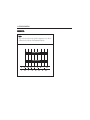
AIR BAG ON-OFF SWITCH
If the instrument panel has the switch pictured
in the following illustration, the vehicle has
an air bag on-off switch that is used to
manually turn on or off the front passenger
frontal and side air bags, and the curtain air
bag for the front passenger and the passenger
sitting directly behind the front passenger.
SEATS AND OCCUPANT PROTECTION SYSTEMS 1–39
This switch should only be turned to the off
position if the person in the front passenger
position falls under the conditions specified
in this manual as follows:
Child age 1 to 12. A child aged 1 to 12 must
ride in the front seat because of any of the
following:
Medical Condition. A passenger has a
medical condition which, according to his or
her physician does both of the following:
• My vehicle has no rear seat.
Infant. An infant (less than 1 year old) must
ride in the front seat because of any of the
following:
• Although children aged 1 to 12 ride in the
rear seat(s) whenever possible, children
aged 1 to 12 sometimes must ride in the
front because no space is available in the
rear seat(s) of my vehicle.
• Causes the passenger airbags to pose a
special risk for the passenger.
• My vehicle has no rear seat.
• My vehicle has a rear seat too small to
accommodate a rear-facing infant seat.
• The infant has a medical condition which,
according to the infant's physician, makes
it necessary for the infant to ride in the
front seat so that the driver can constantly
monitor the child's condition.
• The child has a medical condition which,
according to the child's physician, makes
it necessary for the child to ride in the front
seat so that the driver can constantly
monitor the child's condition.
• Makes the potential harm from the
passenger airbags in a crash greater than
the potential harm from turning off the
airbags and allowing the passenger, even
if belted, to hit the dashboard or windshield
in a crash.
1–40 SEATS AND OCCUPANT PROTECTION SYSTEMS
WARNING
If the front passenger air bags are
turned off for a person who does not
fall under the conditions specified in
this manual, that person will not have
the extra protection of the air bags. In
a crash, the air bags will not be able to
inflate and help protect the person
sitting there. In addition, the curtain air
bag will not be able to protect the
person sitting directly behind the front
passeng
er
passenger
er.. Do not turn off the air bags
unless the person sitting in the front
passenger seat falls under the conditions specified in this manual.
The air bag on-off switch is on the instrument
panel end cap, on the passenger side of the
vehicle. To turn off the front passenger frontal and side air bags, and the curtain air bag
for the front passenger and the passenger
sitting directly behind the front passenger,
insert any key or a coin into the switch, push
in, and move the switch to the off position.
Vehicles equipped with an air bag on-off
switch also have a passenger air bag status
indicator. This indicator is above the glove box,
in the instrument panel.
When the air bags are turned off, the
passenger air bag off light, in the passenger
air bag status indicator comes on to let you
know the air bags for the front passenger and
passenger seated directly behind the front
passenger are off. These air bags remain off
until you turn them back on again.
SEATS AND OCCUPANT PROTECTION SYSTEMS 1–41
WARNING
If the air bag readiness light ever comes
on and stays on, it means that
something may be wrong with the air
bag system. For example, the front
passenger frontal and side air bags, and
the curtain air bag for the front
passenger and the passenger sitting
directly behind the front passenger
could inflate even though the air bag
on-off switch is turned off
off..
To help avoid injur
o your
self or
injuryy tto
yourself
others, have the vehicle serviced right
away
ay..
To turn the air bags on again, insert any key
or a coin into the switch, push in, and move
the switch to the on position.
The front passenger frontal and side air bags,
and the curtain air bag for the front passenger
and passenger sitting directly behind the front
passenger are now enabled, and may inflate.
INSTRUMENTS AND CONTROLS 2–1
2
INSTRUMENTS AND CONTROLS
•
QUICK VIEW - INSTRUMENTS AND CONTROLS .. 2-3
•
CRUISE CONTROL ........................................... 2-45
•
INSTRUMENT CLUSTER ................................... 2-4
•
KEYS ............................................................... 2-47
•
SPEEDOMETER ................................................. 2-5
•
KE
YLESS ENTR
Y SY
STEM .............................. 2-48
KEYLESS
ENTRY
SYSTEM
•
TA CHOMETER ................................................... 2-5
•
DOOR LOCKS .................................................. 2-53
•
FUEL GAUGE .................................................... 2-6
•
ELECTRIC WINDOWS ...................................... 2-57
•
TEMPER
ATURE G
AUGE .................................... 2-6
TEMPERA
GA
•
TAIL
GATE ........................................................ 2-59
AILG
•
INDIC
ATORS AND W
ARNING LLAMPS
AMPS ................ 2-7
INDICA
WARNING
•
BONNET .......................................................... 2-61
•
DRIVER INF
ORMA
TION CENTRE ..................... 2-27
INFORMA
ORMATION
•
INTERIOR COURTESY LAMPS ......................... 2-62
•
SWITCHES AND CONTROLS ............................ 2-32
•
FRONT DOOR STEP LAMP .............................. 2-63
•
FR
ONT P
ASSENGER
AFET
Y BEL
T
FRONT
PASSENGER
ASSENGER’’S S
SAFET
AFETY
BELT
AMP ............................................. 2-45
WARNING LLAMP
•
SUNGLASS HOLDER ........................................ 2-63
(Continued)
•
ELECTRIC SUNROOF ...................................... 2-64
•
COIN STORAGE ................................................ 2-7 1
•
DIGIT
AL CL
OCK ............................................... 2-65
DIGITAL
CLOCK
•
LUGG
AGE C
OMP
AR
T MENT C
OVER .................... 2-7 1
UGGA
COMP
OMPAR
ART
CO
•
CIG
AR LIGHTER AND A
CCESSOR
Y
CIGAR
AC
CESSORY
•
FR
ONT P
ASSENGER SE
AT UNDER
TR
AY ........... 2-7 1
FRONT
PASSENGER
SEA
UNDERTR
TRA
POWER OUTLET .............................................. 2-65
•
LUGGAGE FLOOR NET ..................................... 2-72
•
POR
TABLE ASHTR
AY ....................................... 2-67
PORT
ASHTRA
•
LUGGAGE HOLDING NET .................................. 2-72
•
SE
AT HE
ATER SWIT
CH .................................. 2-68
SEA
HEA
SWITCH
•
UNDER FLOOR STORAGE ................................ 2-72
•
HORN ............................................................ 2-68
•
LUGG
AGE C
OMP
AR
TMENT ST
OR
AGE ............... 2-73
UGGA
COMP
OMPAR
ART
STOR
ORA
•
CUP HOLDER .................................................. 2-69
•
SUN VISORS ................................................... 2-73
•
GLOVE BOX .................................................... 2-69
•
ASSIST GRIP WITH C
CO
OAT HOOK ...................... 2-73
•
CONSOLE BOX ................................................ 2-70
•
ROOF RACK .................................................... 2-74
•
CARD HOLDER ................................................ 2-70
•
ANTENNA ....................................................... 2-75
INSTRUMENTS AND CONTROLS 2–3
QUICK VIEW – INSTRUMENTS AND CONTROLS
1.
2.
3.
4.
5.
6.
Air Vents
Turn and Lane/ Exterior Lamp Controls
Horn
Instrument Cluster
Windshield Wiper/Washer
Hazard Warning Flashers/ ESC OFF
Switch
7. Centre deposit box
8. DCS Switch/ Front Passenger Safety Belt
Reminder Lamp
9. Combination Switch
10. Card Holder
11. Coin Storage
12. Hood Release Lever
13. Steering Wheel Audio Controls
14. Cruise Control/ Climate Control Buttons
15.
16.
17.
18.
19.
20.
21.
22.
Climate Control Systems
Shift Lever
Electric Parking Brake (EPB) Switch
ECO Switch
Cigarette Lighter
Audio System
Glove Box
Passenger Airbag OFF Indicator
2–4 INSTRUMENTS AND CONTROLS
INSTRUMENT
CLUSTER
* The actual cluster in the vehicle may differ from the illustration. For more details refer to the next pages.
INSTRUMENTS AND CONTROLS 2–5
SPEEDOMETER
The speedometer shows vehicle speed in
kilometres per hour (km/h) or miles per hour
(mph).
TA C H O M E T E R
ODOMETER / TRIP ODOMETER
The odometer shows how far your car has
been driven in kilometres.
The tachometer indicates engine speed in
revolutions per minute(rpm).
Never operate the engine at such high rpm
that the tachometer needle is in the red zone.
C0E2005A
There are two independant trip odometers,
which measure the distances your vehicle has
travelled since you last reset this function.
To reset each trip meter to zero, press and
hold the trip odometer button until it resets.
The trip odometer button is located in the
lower right area of the speedometer.
The odometer, trip A and trip B can be
swtiched by pressing the trip odometer button.
<Petrol>
2–6 INSTRUMENTS AND CONTROLS
WARNING
Excessive engine speed can damage the
engine.
• Do not let the engine reach excessive
engine speed, as indicated by the
needle being in the red zone.
This could result in costly repairs.
<Diesel>
FUEL GAUGE
TEMPER
AT U R E
RA
Indicates how much fuel remains in the fuel
tank when the ignition switch is ON.
Indicates engine coolant temperature when
the ignition switch is ON.
After adding fuel and restarting the engine,
the fuel gauge needle slowly moves to show
the new fuel level.
Movement of the fuel within the fuel tank
causes the fuel gauge needle to move when
you brake, accelerate or turn.
G
AU G E
GA
CAUTION
• Do not continue to drive your vehicle
if the temperature gauge needle is in
the red area of the gauge. This means
your vehicle’s engine is overheating.
Driving with an overheated engine can
ee ““O
OVER HE
ATdamag
e your vehicle
HEA
damage
vehicle.. S
See
ING” in the index.
INSTRUMENTS AND CONTROLS 2–7
I N D I CCA
AT O R S A N D W
ARNING
WA
LAMPS
LOW FUEL LE
VEL W
ARNING LLAMP
AMP
LEVEL
WARNING
Illuminates when the ignition is ON and goes
out after about a few seconds.
This warning lamp also comes on when the
fuel tank is low on fuel.
CAUTION
• Do not let your vehicle run out of fuel.
This can damag
e the cat
aly
tic cconver
onver
damage
cataly
alytic
onvertter
er..
Fill up the fuel tank as soon as possible when
warning lamp comes on.
See “FUEL” in the index.
FUEL ECONOMY LAMP
For vehicles with the fuel economy mode
lamp, it comes on when the eco (economy)
switch, located on the center console near the
shifter, is pressed. Press the switch again to
turn off the lamp and exit the fuel saver mode.
For vehicles with petrol engine, when you
move selector lever to manual mode, the
lamp will turn off.
2–8 INSTRUMENTS AND CONTROLS
ABS W
ARNING LLAMP
AMP
WARNING
The ABS warning lamp comes on briefly as
you turn the ignition ON. This means that the
system performs self-checking. The lamp
should go out after about a few seconds.
Contact a workshop for repairs if the ABS
warning lamp does either of the following:
• Does not come on when the ignition is
turned ON.
• Does not go out.
• Comes on while driving
We recommend that you consult your
authorised Chevrolet repairer.
WARNING
• The ABS warning lamp may mean
your br
ak
es ar
e not working pr
operly
brak
akes
are
properly
operly..
Failure to keep your vehicle’s brakes in
proper working condition can cause a
collision resulting in personal injuries
and damage to your vehicle or other
pr
oper
proper
opertty.
If the ABS warning lamp comes on while driving, your vehicle may have an ABS malfunction. Although your vehicle’s brake system will
operate normally without ABS but in the event
of heavy braking the wheels may lock, have a
workshop check the system and make any
necessary repairs as soon as possible. We recommend that you consult your authorised
Chevrolet repairer.
See “ANTI-LOCK BRAKE SYSTEM” in
the index.
AIR BA
GW
ARNING LLAMP
AMP
BAG
WARNING
The air bag warning lamp flashes several
times when you turn the ignition ON. This
means that your air bag system is functional.
INSTRUMENTS AND CONTROLS 2–9
WARNING
If the air bag warning lamp flashes or
stays on while driving, this indicates a
malfunction with the air bag system.
The airbag system will then be switched
off and in the event of an accident may
em check
ed at
not trig
ger
er.. Have the syst
system
checked
trigg
a workshop as soon as possible. We
recommend your authorised Chevrolet
repair
er
epairer
er..
Driving without a properly functioning
air bag system may lead to personal
injur
ven de
ath, in the eevent
vent of an
injuryy, or eeven
death,
accident.
An air bag system malfunction can be
indicated by any of these warning lamp
displays:
• Does not flash or stay on when the ignition
is switched on.
• Stays on after several flashes.
• Flashes while driving.
• Stays on continuously while driving.
For a description of the air bag system and
other occupant protection systems, see
section 1.
AIRBA
G OFF INDIC
ATOR
AIRBAG
INDICA
BR
AKE SY
STEM W
ARNING LLAMP
AMP
BRAKE
SYSTEM
WARNING
The indicator is located above the glove box.
The brake system warning lamp illuminates
when you turn the ignition ON, before the
engine is started.
Illuminates when the front passenger airbag
is deactivated.
This means that the indicator is operating
properly. The lamp should go out after you
start the engine.
2–10 INSTRUMENTS AND CONTROLS
CAUTION
• Do not drive with the brake system
warning lamp on.
• This may mean your brakes are not
working pr
operly
properly
operly..
• Driving with malfunctioning brakes
can lead to a collision resulting in
personal injuries and damage to your
vehicle and other pr
oper
proper
opertty.
When the brake fluid level in the reservoir is
low, the brake system warning lamp comes
on.
If so, follow these steps:
1. Carefully pull off the road and come to a
stop.
2. Check the brake fluid level.
3. Add the recommended brake fluid up to
the MAX mark. See “ADDING BRAKE/
CLUTCH FLUID” in the index.
4. Drive carefully at a safe speed to a workshop to have the brakes inspected if the
following conditions exist:
• You judge your vehicle’s brake system
to be safe.
We recommend that you consult your
authorised Chevrolet repairer.
5. Have your vehicle towed to a workshop for
inspection and repair if the following conditions exist:
• You find leaks in the brake system.
• The brake system warning lamp stays
on.
We recommend that you consult your
authorised Chevrolet repairer.
ELECTRIC PARKING BRAKE LAMP
For vehicles with the Electric Parking Brake
(EPB), the parking brake status lamp comes
on briefly as the engine is started. If it does
not come on, have the vehicle serviced by your
authorised repairer.
The parking brake status lamp comes on
when the parking brake is applied. If the lamp
continues flashing after the parking brake is
released, or while driving, there is a problem
with the Electric Parking Brake system.
If the lamp does not come on, or remains
flashing, consult your authorised repairer.
INSTRUMENTS AND CONTROLS 2–11
For vehicles with the Electric Parking Brake
(EPB), the parking brake warning lamp should
come on briefly when the vehicle is in ON/
START. If it does not come on then, have it
fixed so it will be ready to warn if there is a
problem.
If this lamp comes on, there is a problem with
a system on the vehicle that is causing the
parking brake system to work at a reduced
level. The vehicle can still be driven, but should
be taken to a dealer as soon as possible. See
“PARKING BRAKE” in the index.
For vehicles with the Electric Parking Brake
(EPB), this indicator comes on when the EPB
switch is released without pressing the brake
pedal. Always press the brake pedal before
pressing the EPB switch to release the Electric
Parking Brake.
CHAR
GING SY
STEM W
ARNING LLAMP
AMP
CHARGING
SYSTEM
WARNING
Indicates the battery is being discharged. The
lamp should come on when you turn the
ignition ON. The lamp should go out when you
start the engine.
CAUTION
The charging system warning lamp
indicates there may be a problem with
your charging system.
• Do not drive your vehicle when the
charging system warning lamp is on.
Driving your vehicle while its charging
system is malfunctioning can cause
damage to the vehicle.
2–12 INSTRUMENTS AND CONTROLS
If the charging system warning lamp comes
on while you are driving:
1. Pull safely off the road.
ENGINE OIL PRESSURE W
ARNING
WARNING
LAMP
2. Stop your vehicle.
Illuminates briefly when the ignition is
switched on before the engine starts.
3. Make sure the drive belt is not loose or
broken. See “DRIVE BELT” in the index.
The lamp should go out after the engine
starts.
CAUTION
A loose or broken drive belt can cause
the engine to overheat.
• Do not drive your vehicle if the drive
belt is loose or broken.
An overheated engine can damage your
vehicle and result in costly repairs.
4. If the drive belt is in proper working order
but the charging system warning lamp
stays on, there may be a problem somewhere in the charging system.
Take your vehicle to a workshop for repairs
as soon as possible. We recommend your
authorised Chevrolet repairer.
If the engine oil pressure warning lamp comes
on while driving, your engine oil pressure may
be dangerously low. Stop the engine immediately and check the oil level.
See “ENGINE OIL” in the index for the correct
checking procedure.
CAUTION
Your engine oil pr
essur
e may be dang
er
er-pressur
essure
danger
ously low
low..
• Do not drive with the engine oil pressure warning lamp on.
Driving your vehicle with low oil
pressure can result in costly damage to
your vehicle.
If the oil level is low, add the specified engine
oil to the correct level. See “CHANGING
ENGINE OIL AND FILTER” in the index.
If the oil level is normal, have a workshop check
your vehicle’s lubricating system. We recommend your authorised Chevrolet repairer.
INSTRUMENTS AND CONTROLS 2–13
MALFUNCTION INDIC
ATOR LLAMP
AMP
INDICA
Illuminates briefly as you turn the ignition ON,
before you start the engine.
The lamp should go out after the engine is
started.
CAUTION
The indicator lamp signals that your
vehicle has a problem that requires
attention. Driving with the malfunction
indicator lamp on can damage the
emissions control system and can
affect the fuel economy and driveability
of your vehicle.
Consult a workshop to repair the
problem as soon as possible. We recommend your authorised Che
vr
olet rrepair
epair
er
Chevr
vrolet
epairer
er..
The Malfunction Indicator Lamp (MIL) will
illuminate if a fault exists in the emission related components or related sub systems.
It will stay on as long as the Engine Control
Module (ECM) detects the fault. If a severe
misfire level is detected, the MIL will blink
continuously. Severe misfire can cause
catalytic converter damage.
The Malfunction Indicator Lamp (MIL) will
also illuminate to indicate that there is a
malfunction in the Diesel Particulate Filter
(DPF). If this happens, you should consult a
workshop to repair the problem immediately.
We recommend your authorised Chevrolet
repairer. See "DIESEL PARTICULATE FILTER
(DPF)" in the index for more information.
Your vehicle’s electronic system will switch to
an emergency running programme so you may
continue to drive. However, you should consult a workshop to repair the problem as soon
as possible. We recommend your authorised
Chevrolet repairer.
2–14 INSTRUMENTS AND CONTROLS
If the MIL comes on briefly and then goes out
again, this is normal and does not indicate a
system fault.
SELECTOR LEVER POSITION
INDIC
ATOR ((A
AUT
OMA
TIC TR
ANS
A XLE
INDICA
UTOMA
OMATIC
TRANS
ANSA
XLE))
FR
ONT F
OG LLA
AMP INDIC
ATOR
FRONT
FOG
INDICA
Shows the position of the transaxle gear
selector lever.
See “FRONT FOG LAMP” in the index.
C0E2010A
Illuminates when the front fog lamps are on.
INSTRUMENTS AND CONTROLS 2–15
RE
AR F
OG LLA
AMP INDIC
ATOR
REAR
FOG
INDICA
DRIVER
AFET
Y BEL
T REMINDER
DRIVER’’S S
SAFET
AFETY
BELT
Illuminates when the rear fog lamps are on.
Driver’s safety belt warning lamp comes on
for about a few seconds when the ignition
switch is turned ON, and then goes out. This
means that the system performs selfchecking. After the engine is started, unless
the driver’s safety belt is securely fastened,
the lamp will flash for about 90 seconds and
then illuminate until the driver’s safety belt
is fastened.
See “REAR FOG LAMP” in the index.
After that, if the vehicle speed goes over about
22km/h, the lamp will flash again along with
the warning chime for about 90 seconds and
then illuminate until the driver’s safety belt
is fastened.
NOTE
If you ffast
ast
en the driver
et
asten
driver’’s saf
safet
etyy belt
when the warming lamp comes on or
flashes after the system performs
selfchecking, the safety belt warning
ely
lamp will ggo
o out immediat
immediately
ely..
If you want to stop the warning chime instead
of fastening the safety belt, do the followings:
When the ignition is ON, insert the latch plate
into safety belt buckle and then extract it. This
opeartion should be performed two times
within 10 seconds.
The warning chime will be able to sound again
a few minutes after the ignition is OFF.
2–16 INSTRUMENTS AND CONTROLS
TURN SIGNAL / HAZ
ARD W
ARNING
HAZARD
WARNING
FL
ASHER INDIC
ATORS
INDICA
FLASHER
Turn signal / hazard warning flasher indicators verify that the exterior turn signals or
hazard warning flashers are working properly.
If the green arrows don’t flash when you signal a turn or push the hazard warning button,
check the fuse and replace any that are not
operating properly.
L4W2221A
CAUTION
These indicators are required for safe
driving.
Failure to keep these indicators in proper
working condition can lead to accidents
that can result in personal injuries or
damag
e tto
o your vehicle or other pr
oper
damage
proper
opertty.
HIGH BE
AM INDIC
ATOR
BEAM
INDICA
The high-beam indicator illuminates when the
headlamp high-beams are on.
INSTRUMENTS AND CONTROLS 2–17
ELE
CTR
ONIC ST
ABILIT
YC
ONTR
OL (ESC
ELECTR
CTRONIC
STABILIT
ABILITY
CONTR
ONTROL
(ESC))
ATOR
INDICA
OFF INDIC
ELE
CTR
ONIC ST
ABILIT
YC
ONTR
(ESC))
ELECTR
CTRONIC
STABILIT
ABILITY
CONTR
ONTROL
OL (ESC
ACTIVE AND W
ARNING LLAMP
AMP
WARNING
Illuminates when the ignition is ON and goes
out after about a few seconds.
Illuminates when the ignition is ON and goes
out after about a few seconds.
The ESC off indicator illuminates to indicate
that you have cancelled the system by pressing ESC OFF located on the centre of the instrument panel.
This lamp blinks while ESC is operating and
illuminates to indicate that there is a malfunction in the system.
See “ELECTRONIC STABILITY CONTROL SYSTEM” in the index for more information.
See “ELECTRONIC STABILITY CONTROL SYSTEM” in the index for more information.
DESCENT CONTROL SYSTEM (DCS)
ACTIVE AND NO
T RE
AD
Y/ WARNING
NOT
READ
ADY
LAMP
The green DCS lamp is DCS active indicator
and the amber DCS lamp is DCS not ready &
warning lamp.
DCS active indicator illuminates(as green
colour) when DCS is ready for use and
blinks(as green colour) while DCS is operating by pressing the DCS button located on the
centre of the instrument panel.
2–18 INSTRUMENTS AND CONTROLS
DCS not ready & warning lamp works as the
following:
IMMOBILISER SY
STEM W
ARNING
SYSTEM
WARNING
LAMP
PARKING ASSIST
ANCE SY
STEM
ASSISTANCE
SYSTEM
WARNING LLAMP
AMP
• Blinks (as amber colour) to indicate that
DCS is not ready for condition to operate
due to the high temperature (about
350~400°C) of friction material(front pad)
through severe or repeated braking. This
lamp will disappear when the temperature
of friction material(front pad) is lower than
350°C.
Illuminates when the ignition is ON and goes
out after about a few seconds.
Illuminates when the ignition is ON and goes
out after about a few seconds.
This lamp comes on to indicate that there is
a malfunction in the immobiliser system.
This lamp illuminates to indicate that there
is a malfunction in the system.
See “IMMOBILISER SYSTEM” in the index.
See “PARKING ASSISTANCE SYSTEM” in the
index for more information.
• Illuminates (as amber colour) to indicate
that there is a malfunction in the system
due to the high temperature(over 400°C)
of friction material(front pad) through severe or repeated braking. This lamp also
will disappear when temperature of friction material(front pad) is lower than
350°C.
The blinking and illuminating of DCS not
ready & warning lamp notify you that the friction material needs to cool down(drive your
vehicle enough without braking as much as
possible). Above temperature may differ
somewhat according to vehicle condition or
environment(season or outer temperature) or
etc.
See “DESCENT CONTROL SYSTEM” in the
index for more information.
CAUTION
If the immobiliser system warning lamp
comes on, you should cconsult
onsult a work
work-shop to repair the problem as soon as
possible. We recommend your
authorised Che
vr
olet rrepair
epair
er
vrolet
Chevr
epairer
er..
CAUTION
If the parking assistance system
warning lamp comes on, you should
consult a workshop to repair the problem
as soon as possible. We recommend your
er
authorised Che
vr
olet rrepair
epair
Chevr
vrolet
epairer
er..
INSTRUMENTS AND CONTROLS 2–19
LOW WINDSCREEN W
ASHER FL
UID
WASHER
FLUID
LE
VEL W
ARNING LLAMP
AMP
LEVEL
WARNING
Illuminates when the ignition is ON and goes
out after about a few seconds.
This lamp comes on when the washer fluid
level is low. Add washer fluid when you see
this lamp come on.
See “WINDSCREEN WASHER FLUID” in the
index.
SERVICE VEHICLE SOON LAMP
Illuminates when the ignition is ON and goes
out after about a few seconds.
CAUTION
The service vehicle soon lamp signals
that your vehicle has a problem that
requires attention. Driving with the
lamp on can damage the non-emission
related system.
Consult a workshop to repair the
problem as soon as possible. We recommend your authorised Che
vr
olet rrepair
epair
er
Chevr
vrolet
epairer
er..
The service vehicle soon lamp will illuminate
if a fault exists in the non-emission related
components or related sub systems.
It will stay on as long as the Electronic
Control Unit (ECU) detects the fault.
C7E2021A
2–20 INSTRUMENTS AND CONTROLS
ENGINE C
OOL
ANT TEMPER
ATURE
COOL
OOLANT
TEMPERA
WARNING LLAMP
AMP
Illuminates when the ignition is ON and goes
out after about a few seconds.
This lamp tells you that the engine coolant
has overheated.
If you have been operating your vehicle under
normal driving conditions, you should pull off
the road, stop your vehicle and let the engine
idle for a few minutes.
If the lamp does not go out, you should switch
the engine off and consult a workshop as soon
as possible. We recommend your authorised
Chevrolet repairer.
See “OVERHEATING” in the index.
DOOR OPEN W
ARNING LLAMP
AMP
WARNING
TAIL
GATE OPEN W
ARNING LLAMP
AMP
AILG
WARNING
Illuminates when a door is open or not
securely latched.
Illuminates when the tailgate or tailgate
window is open or not securely latched.
INSTRUMENTS AND CONTROLS 2–21
CR
UISE C
ONTR
OL INDIC
ATOR
CRUISE
CONTR
ONTROL
INDICA
Illuminates when cruise control is set. It will
go out when cruise control is turned off.
See “CRUISE CONTROL” in the index.
ALL
ALL--WHEEL DRIVE ((A
WD)) SY
SYSTEM
AWD
STEM
AMP ((A
AWD only)
WARNING LLAMP
Illuminates when the ignition is ON and goes
out after about a few seconds.
This lamp blinks when AWD system is
temporarily disabled and illuminates to
indicate that there is a malfunction in the
AWD system.
If AWD system warning lamp comes on, you
should consult a workshop to repair the problem as soon as possible. We recommend your
authorised Chevrolet repairer.
See “ALL-WHEEL DRIVE SYSTEM” in the index for more information.
CHANGE ENGINE OIL LAMP
Illuminates when the ignition is ON and goes
out after about a few seconds.
Your vehicle may have an engine oil life
system that lets you know when to change
the engine oil.
When the change engine oil lamp comes on,
it means that the engine oil needs to be
changed.
Once the engine oil has been changed, the
engine oil life system must be reset. After
reset, the change engine oil lamp will go out.
2–22 INSTRUMENTS AND CONTROLS
See “ENGINE OIL LIFE SYSTEM” in the index
for more information on how to reset the
system.
GL
OW PL
UG INDIC
ATOR (Diesel only)
GLO
PLUG
INDICA
Illuminates when the ignition is ON and stays
on for a short time or may go off right away.
The waiting time will vary according to the
engine coolant temperature.
When the glow plugs are sufficiently heated
for cold starting, the light will go out. Then,
the engine should be started.
See "STARTING THE DIESEL ENGINE" in
the index for more information.
CAUTION
When the glow plug indicator comes on
while driving or the engine cannot be
st
ar
operly
onsult a
artted pr
properly
operly,, you should cconsult
star
workshop to repair the problem as soon
as possible. We recommend your
er
authorised Che
vr
olet rrepair
epair
er..
Chevr
vrolet
epairer
INSTRUMENTS AND CONTROLS 2–23
DIESEL P
AR
TICUL
ATE FIL
PAR
ARTICUL
TICULA
FILTER
(DPF))
TER (DPF
ATOR (Diesel only)
INDICA
INDIC
If DPF requires cleaning or previous driving
conditions did not enable automatic cleaning,
DPF indicator illuminates or flashes. Continue
driving, keeping engine speed above
2,000 revolutions per minute (Shift down if
necessary.) until the indicator goes off. The indicator will
go off as soon as the selfcleaning operation
is complete. Cleaning takes place quickest at
high engine speeds and loads.
Stopping the journey or switching off the
engine during cleaning is not recommended.
CAUTION
If the cleaning process is interrupted
more than once, there is a risk of
provoking severe engine damage.
See “DIESEL PARTICULATE FILTER (DPF)” in
the index for more information.
WATER IN FUEL W
ARNING LLAMP
AMP
WARNING
(Diesel only)
When the water level in the fuel filter exceeds
a certain level, this warning lamp comes on.
If this condition occurs, immediately drain the
water from fuel filter.
The warning lamp will go off when the
draining is completed.
To drain the water from fuel filter, you need
to consult a workshop to do it. We recommend
your authorised Chevrolet repairer.
2–24 INSTRUMENTS AND CONTROLS
CAUTION
• The fuel system in the engine may
get serious damage if you keep driving
while the warning lamp is coming on.
Pr
ompt ccorr
essar
orr
ection should be nec
Prompt
orrection
necessar
essaryy.
• Using low quality fuel could result in
serious damage to the engine due to
the water or impurities in fuel. Never
use low quality fuel.
• If the warning lamp still illuminates
er dr
aining the w
at
er
after
draining
wat
ater
er,, you should
aft
consult a workshop to repair the
problem as soon as possible. We
recommend your authorised Chevrolet
repair
er
epairer
er..
SSPS W
ARNING LLAMP
AMP
WARNING
TR
AILER INDIC
ATOR
TRAILER
INDICA
The speed sensitive power steering (SSPS)
warning lamp comes on as you turn the ignition ON. The lamp should go out after about a
few seconds.
Illuminates when the trailer is connected to
your vehicle. It will go out when the trailer is
disconnected.
If the SSPS warning lamp does either of the
following, consult a workshop as soon as
possible. We recommend your authorised
repairer.
• Does not come on when the ignition is
turned ON.
• Does not go out.
• Comes on while driving.
See “SPEED SENSITIVE POWER STEERING” in
the index.
INSTRUMENTS AND CONTROLS 2–25
SE
CURIT
Y INDIC
ATOR
SECURIT
CURITY
INDICA
ANTITHEFT OFF INDIC
ATOR
ANTI-THEFT
INDICA
LIGHT ON INDIC
ATOR
INDICA
Indicates the anti-theft system is working.
If your vehicle has additional anti-theft system
related to Thatcham insurance, the anti-theft
off indicator illuminates to indicate that you
have disabled the intrusion and inclination
senor by pressing the button located on the
headliner. If you press the button again, the
indicator will go out. See "SIREN SOUND" in
this section for more information.
Notifies the driver when the park lamps have
been activated.
The security indicator goes out when doors
are unlocked using the keyless entry
transmitter or key.
The security indicator comes on when you lock
the doors using the keyless entry transmitter
or key.
See “KEYLESS ENTRY SYSTEM” in the index.
C7E2033P
C0E2011A
2–26 INSTRUMENTS AND CONTROLS
ENGINE OIL LE
VEL W
ARNING LLAMP
AMP
LEVEL
WARNING
Illuminates when the ignition is ON and goes
out after a few seconds.
This lamp illuminates when engine oil level
is too low.
If engine oil level warning lamp comes on,
check engine oil level and top up if necessary.
See “CHECKING ENGINE OIL LEVEL” in the
index for more information on how to check
the engine oil.
INSTRUMENTS AND CONTROLS 2–27
D R I V E R I N FFO
ORMA
T I O N C E N T R E ( D I CC))
AT
The DIC is the Driver Information Centre that
displays the trip computer, display panel for
automatic temperature control, outside
temperature and compass information when
ignition switch is ON.
C7D2008A
1.
2.
3.
4.
FATC (Fully Automatic Temperature Control) display panel
Outside temperature
Trip computer
Compass
2–28 INSTRUMENTS AND CONTROLS
TRIP COMPUTER
Driving Distance For Remaining Fuel
Trip computer provides the driver with driving
information such as driving distance for
remaining fuel, average fuel consumption,
average speed and driving time.
This mode indicates the estimated driving
distance to empty from the current fuel in the
fuel tank.
Each time you press the MODE button, the display changes in the following order:
When the distance to empty is less than
50 km (30 miles), --- will display.
Driving distance for remaining fuel o
Average speed o Driving time o
Average fuel consumption o Driving distance
for remaining fuel
To reset average speed or driving time or average fuel consumption, press the MODE button for more than 2 seconds.
To change the distance unit, do the following:
1. Press the SET button for more than 2 seconds. The temperature unit will blink.
2. Press the SET button again. The distance
unit will blink.
or button to change the
3. Press the
distance unit (km Q mile).
L7D2087A
NOTE
• The driving distance for remaining
fuel can differ from the actual
distance according to driving conditions, driving pattern or vehicle speed.
INSTRUMENTS AND CONTROLS 2–29
Average Speed
Driving Time
Average Fuel Consumption
This mode indicates the average speed.
To reset the average speed to zero, press the
MODE button for more than 2 seconds.
This mode indicates the total driving time.
To reset the driving time to zero, press the
MODE button for more than 2 seconds.
The driving time will be initialised to 0:00
after being displayed to 99:59.
This mode indicates the vehicle’s average fuel
consumption.
NOTE
• Average fuel consumption is reset to
10.0 if the battery is disconnected.
• To rreset
e fuel cconsumponsumpeset the aver
ag
averag
age
tion to zero, press the MODE button
for more than 2 seconds.
L7D2085A
L7D2089A
L7D2086A
2–30 INSTRUMENTS AND CONTROLS
NOTE
• The average fuel consumption can
differ from the actual average fuel
consumption according to driving
conditions.
• The average fuel consumption can
vary according to the driving conditions, driving pattern or vehicle speed.
COMP
ASS
OMPASS
Compass Calibration
This displays the vehicle’s driving direction to
8–direction (N, NE, E, SE, S, SW, W, NW).
Whenever the DIC or the battery is
disconnected, the DIC must be recalibrated.
To do this, the vehicle must be driven through
360q. Until calibrated the compass will not
function correctly.
1. If you press the MODE and SET button
simultaneously for more than 2 seconds,
the compass display flashes.
INSTRUMENTS AND CONTROLS 2–31
2. Turn the vehicle around 1 complete circle
within 90 seconds slowly, then the
calibration will be accomplished.
Release conditions for the compass
calibration
3. When the calibration is finished, the
compass display does not flash anymore.
You can turn around to any direction, left
or right.
• When the vehicle is not turned within
90 seconds after calibration mode started.
If enough space is not available to turn
around 1 circle, turn the vehicle around as
shown in the below figure.
• Press the SET button twice continuously.
NOTE
• The direction will be displayed while
driving.
• If the compass display continues to
flash, turn around again slowly until
it ggoes
oes off
off..
NOTE
In the compass calibration mode, press
the SET button to move to deflection
calibration mode. At that time, press
or button to adjust deflection calibration value.
L7D2102A
CAUTION
If there are mobile telephones or
magnetic bodies around the DIC, the
at
ed pr
operly
compass may not be oper
ated
properly
operly..
operat
2–32 INSTRUMENTS AND CONTROLS
SWITCHES AND CONTROLS
FATC DISPL
AY P
ANEL
SIDE
DISPLA
PANEL
ANEL//OUT
OUTSIDE
TEMPER
ATURE
TEMPERA
See “AUTOMATIC CLIMATE CONTROL” in the
index.
LIGHT SWITCH
To turn the head, tail and parking lamps on
or off, twist the end of the combination switch
lever.
The light switch has three positions which
activate various lamp functions as follows:
• OFF
OFF: All the lights are off.
The light switch with automatic lamp control
has four positions which activate various lamp
functions as follows:
•
: All the lights are off.
O: Turn the lamps on or off automati• AUT
UTO
or
cally to illuminate in the position
by sensing how dark it is outside.
(Default position)
•
: The parking lamps, tail lamps,
number plate lamps, and instrument panel
lamps are illuminated.
•
: The parking lamps, tail lamps, number plate lamps, and instrument panel lamps
are illuminated.
•
: The low-beam headlamps and
all of the above lamps are illuminated.
: The low-beam headlamps and
•
the lamps to come on in the position
are illuminated.
INSTRUMENTS AND CONTROLS 2–33
To turn the automatic lamp control off, turn
the light switch lever to the OFF position. The
lever will return automatically to its normal
original when released.
DIMMER SWITCH
HEADLAMP LEVELLING SWITCH
The dimmer switch controls the brightness of
the instrument panel lamps.
With the low beam switched on, adjust
headlamp range to suit the vehicle load.
To turn the automatic lamp control on, turn
the light switch lever to the OFF position
again.
To dim the panel illumination, push the button and turn it clockwise.
0 = Front seat occupied
To brighten the illumination, push the button
and turn it counterclockwise.
2 = All seats occupied and load in the
luggage compartment
CAUTION
In order for this feature to work properly
e not tto
o plac
e stick
er
erly,, be sur
sure
place
sticker
erss or other
items over the sunlight sensor located
in front of the windscreen defroster
vents. Doing so could cause the sensor
to malfunction.
NOTE
If you open a driver
driver’’s door or when you
press UNLOCK button on the remote
ansmitt
er
k eyless entr
ansmitter
er,, instrument
entryy tr
transmitt
panel lamps will come on automatically
and stay on for about 30 seconds.
1 = All seats occupied
3 = Driver’s seat occupied and load in the
luggage compartment
2–34 INSTRUMENTS AND CONTROLS
UNNING LIGHT
S
RUNNING
LIGHTS
DAY TIME R
LAMPS ON REMINDER
DOOR
DOOR--TO-DOOR LIGHT FUNCTION
If so equipped, the daytime running lights
illuminates automatically when the engine is
started.
• Engine is stopped.
If you open the driver’s door with the ignition
off and the light switch is in the position
or
you will hear a warning chime.
But, when you turn the lamps on again after
tunring them off while warning chime sounds,
you will not hear a warning chime.
The door-to-door light function provides a period of exterior lighting as you leave the area
around your vehicle when it is dark enough
outside. The feature is activated when the
exterior lamps are on due to the automatic
lamp control feature, and when the ignition
is turned off.
• Parking lamps on.
BA
TTER
YR
UNDO
WN PR
OTE
CTION
TTERY
RUNDO
UNDOWN
PRO
TECTION
BATTER
• Low-beam lamps on.
Your vehicle has a feature to help prevent you
from draining the battery in case you
accidentally leave on the lamps like
headlamps, parking lamps, fog lamps, etc. If
you leave any of these lamps on, they will
automatically turn off after 10 minutes after
you turn the ignition switch to the OFF position.
The daytime running lights will turn off under
the following conditions:
Battery rundown protection will not operate
when you turn the lamps on 10 minutes after
this feature operated.
APPROACHING LIGHTING
The feature is activated when the light switch
is in the AUTO position and when it is dark
enough outside.
When you press the UNLOCK button on the
remote keyless entry to get in your vehicle,
hazard lamps flash twice and the exterior
lamps illuminate automatically for about
20 seconds.
INSTRUMENTS AND CONTROLS 2–35
WIPER A
CTIV
ATED LIGHTING
ACTIV
CTIVA
INDIC
ATOR ST
ALK
INDICA
STALK
The feature is activated when the light switch
is in the AUTO position.
RIGHT turn:
Move the indicator stalk up.
LEFT turn:
Move the indicator stalk down.
If the windscreen wipers continue to operate
8 cycles, the exterior lamps will illuminate
automatically.
The turn signal will shut off automatically and
the lever will return to its normal position after
you have completed the turn.
When changing lanes, move the indicator
stalk part way and hold it there. When you
release the lever, it will return to its normal
position.
NOTE
When you move the indicator stalk
lightly upward or downward and release
it, the turn signal lamps will operate
automatically three times.
2–36 INSTRUMENTS AND CONTROLS
HIGH BEAM SWITCH
To turn the high-beam headlamps on:
• Make sure the low-beam headlamps are
on.
• Push the combination switch lever toward
the instrument panel.
The headlamp high-beam indicator illuminates when headlamps are on high beam.
To switch from high-beam headlamps to lowbeam, pull the combination switch lever back
toward you, to its normal position.
CAUTION
• Always switch the high-beam
headlamps to low-beam when you
approach on coming vehicles or when
other vehicles are ahead.
High-beam headlamps can temporarily
blind other drivers, which could result in
a collision.
PASSING LIGHT SWIT
CH
SWITCH
To flash the high-beam headlamps, pull the
combination switch lever toward you and
release it. The lever will return to its normal
position when you release it.
The high-beam headlamps will stay on as
long as you hold the combination switch
lever toward you.
INSTRUMENTS AND CONTROLS 2–37
The front fog lamp indicator in the instrument
panel illuminates when the fog lamps are
turned on.
FRONT FOG LAMP SWITCH
Fog lamps provide:
• Extra illumination to the sides of the road
ahead.
• Improved visibility in fog or snow.
To turn the fog lamps on:
• Make sure the light switch is in the
position.
or
• Rotate the ring on the middle of the light
. The ring will return autoswitch lever to
matically to its normal position when released.
To turn the fog lamps off, rotate the ring to
position again. The front fog lamp indicator will go off.
If your vehicle has the automatic lamp control, parking lamps and low beam headlamps
will come on simultaneously when turning on
the front fog lamps.
REAR FOG LAMP SWITCH
To turn the rear fog lamps on, rotate the ring
on the middle of the light switch lever to
when the low beam headlamps are on, or
when the parking lamps and the front fog
lamps are on. The ring will return automatically to its normal position when released.
The rear fog lamp indicator in the instrument
panel illuminates when the fog lamps are
turned on.
To turn the fog lamps off, turn the ring to
position again. The rear fog lamp indicator will go off.
2–38 INSTRUMENTS AND CONTROLS
If your vehicle has the automatic lamp control,
parking lamps and low beam headlamps will
come on simultaneously when turning on the
rear fog lamps.
WINDSCREEN WIPERS
CAUTION
• Less than clear vision for the driver
can lead to an accident resulting in
personal injury and damage to your
vehicle or other pr
oper
proper
opertty.
• Do not operate the windscreen wipers
when the windscreen is dry or
obstructed, as with snow or ice. Using
the wipers on an obstructed
windscreen can damage the wiper
blades, wiper mot
or
motor
or,, and glass.
• Check blades are not frozen to
windows before operating in cold
we
ather
ation while blade
weather
ather.. Wiper oper
operation
or
is fr
ozen can damag
e wiper mot
frozen
damage
motor
or..
To operate the windscreen wipers, turn the
ignition ACC or ON and move the windscreen
wiper/washer lever upward.
The windscreen wipers operate in the
following four positions:
• OFF
OFF: System off. Default position.
• INT
INT: Intermittent operation. (Move the
lever to this position to choose a delayed
wiping cycle. Rotate the intermittent
adjustment band to set for shorter or longer
delay cycles. S mean the wiper movement
is less frequent and F mean the wiper
movement is more frequent. During
intermittent wiping mode, the cycle delay
time is also affected by vehicle speed.
INSTRUMENTS AND CONTROLS 2–39
As your vehicle speed increases, your delay cycle time will automatically decrease.)
• LO
LO: Continuous wipe, slow speed. Lever up
two levels.
• HI
HI: Continuous wipe, fast speed. Lever up
three levels.
NOTE
Wiper blades will wear out and not wipe
properly reducing forward vision.
• Replace worn wiper blades.
Misting function
To operate the windscreen wipers once in case
of light rain or mist, lightly move the
windscreen wiper/washer lever downward and
release it.
The lever will return automatically to its normal position when released.
The wipers will operate through one cycle.
Automatic wipers with rain sensor
The rain sensor detects the amount of water
on the windscreen and automatically regulates
the windscreen wipers.
To operate the windscreen wipers automatically, move the windscreen wiper/washer lever
toward the AUTO position.
The sensitivity of the system can be adjusted
by turning the band of the windscreen wiper/
washer lever up or down.
To turn the system off, move the windscreen
wiper/washer lever toward the OFF position.
CAUTION
Do not switch on the windscreen wipers
or set them to automatic operation with
rain sensor in car washes. This could
damage the wiper blades or wiper
system.
The windscreen wipers operate once to check
the system when the ignition switch is turned
to ACC while the wiper lever is in the AUTO
position.
So as to ensure proper operation of the rain
sensor, the sensor field must be free from dust
and dirt. Vehicles with rain sensor can be
identified by the sensor field near the top of
the windscreen.
The wipers are not operated when select lever
of automatic transaxle is in "N" position and
vehicle speed is lower than 5km/h.
2–40 INSTRUMENTS AND CONTROLS
WINDSCREEN W
ASHER
WASHER
CAUTION
• Less than clear vision for the driver
can lead to an accident resulting in
personal injury and damage to your
vehicle or other pr
oper
proper
opertty.
• Do not spray washer fluid on the
windscr
een in fr
eezing we
ather
windscreen
freezing
weather
ather..
• Warm the windscreen before you
at
e the windscr
een w
asher
operat
ate
windscreen
washer
asher..
oper
Washer fluid can form ice on a frozen
windscreen and obstruct your vision.
To spray washer fluid on the windscreen:
• Turn the ignition ACC or ON.
• Pull the windscreen wiper / washer lever
toward you.
When you pull the lever for less than
0.6 seconds, the following happens:
• Washer fluid sprays onto the windscreen.
(The windscreen wipers do not operate)
When you pull the lever for more than
0.6 seconds:
• Washer fluid sprays onto the windscreen.
• The windscreen wipers operate for 2 cycles
after the lever is released and 1 more cycle
after 3 seconds.
CAUTION
• Do not operate the windscreen washer
continuously for more than 10 seconds, or when the washer fluid tank
is empt
emptyy.
This can cause the washer motor to
overheat resulting in costly repairs.
INSTRUMENTS AND CONTROLS 2–41
Washer fluid refill
For the recommended procedure for refilling
your windscreen washer reservoir, see
“WINDSCREEN WASHER FLUID” in the index.
TAIL
GATE WINDO
W WIPER AND
AILG
WINDOW
WASHER
CAUTION
• Less than clear vision for the driver
can lead to an accident resulting in
personal injury and damage to your
oper
vehicle or other pr
proper
opertty.
• Do not operate the tailgate window
wiper when the tailgate window is dry
or obstructed, as with snow or ice.
Using the wiper on an obstructed
window can damage the wiper blades,
wiper mot
or
motor
or,, and glass.
• Check blade is not frozen to window
bef
or
e oper
ating in ccold
old we
ather
befor
ore
operating
weather
ather..
Wiper operation while blade is frozen
or
can damag
e wiper mot
or..
damage
motor
To operate the tailgate wiper, turn the ignition ACC or ON and rotate the end of the
windscreen wiper/washer lever upward.
The tailgate wiper operates in the following
three positions:
• OFF
OFF: System off. Default position.
• INT
INT: Intermittent operation.
• LO
LO: Continuous wipe, slow speed.
2–42 INSTRUMENTS AND CONTROLS
To spray washer fluid on the tailgate window,
press the button at the end of the lever until
the washers begin. When you release the
button, the washers will stop, but the wipers
will continue to wipe for about three times.
CAUTION
• Do not spray washer fluid on the
tailg
at
e window in fr
eezing we
ather
ailgat
ate
freezing
weather
ather..
• Warm the tailgate window before you
oper
at
e the ttailg
ailg
at
e window w
asher
operat
ate
ailgat
ate
washer
asher..
Washer fluid can form ice on a frozen
tailgate window and obstruct your
vision.
CAUTION
• Do not operate the tailgate window
washer continuously for more than
10 seconds, or when the washer fluid
tank is empt
emptyy.
This can cause the washer motor to
overheat resulting in costly repairs.
Rear smart wiper
To achieve a clear vision in the rain, the rear
wiper will operate automatically when you
select reverse gear while the front wiper is
operating.
Washer fluid refill
For the recommended procedure for refilling
your windscreen washer reservoir, see
“WINDSCREEN WASHER FLUID” in the index.
INSTRUMENTS AND CONTROLS 2–43
HE
ADL
AMP W
ASHER
HEADL
ADLAMP
WASHER
HAZ
ARD W
ARNING FL
ASHER BUTT
ON
HAZARD
WARNING
FLASHER
BUTTON
Your vehicle may have headlamp washers. The
headlamp washers clear debris from the
headlamp lenses.
Use hazard warning flashers in the following
situations:
To wash the headlamps, press the washer
button located on the left side of the instrument panel when the headlamps are turned
on. Washer fluid is sprayed onto the
headlamps. Then the headlamp washer
system is disabled for about 2 minutes. If
washer fluid level is low, the washer system
cannot be operated for about 4 minutes after
spraying.
• When your vehicle is in a traffic hazard.
• To warn others of emergency conditions.
You can operate the hazard flash function with
the ignition ON or OFF.
To activate the hazard warning flashers, push
the hazard warning flasher button.
To turn off the flashers, push the button again.
REAR WINDOW AND OUTSIDE
MIRROR DEFROSTER BUTTON
CAUTION
D o not use the defroster under the
following conditions:
• Engine is not running.
e just st
ar
ting your vehicle
• You ar
are
star
arting
vehicle..
• There is a buildup of snow or ice on
the rear window or windscreen.
If you use your vehicle’s defroster under
these conditions, you can discharge your
vehicle
er
vehicle’’s batt
batter
eryy.
This can damage your vehicle, requiring
the replacement of some parts.
2–44 INSTRUMENTS AND CONTROLS
To turn the defroster on, turn the ignition to
ON and push the rear window and outside
mirror defroster button. The indicator light in
the button will illuminate.
The defroster will be automatically turned off
after approximately 15 minutes.
To turn the defroster off manually, push the
button again.
Make sure you turn the defroster off after
achieving clear vision.
CAUTION
Lack of proper maintenance can damage
your vehicle’s heater element or scratch
the glass.
• Do not use sharp instruments or abrasive window cleaners on your vehicle’s
rear window
window..
• Do not scratch or damage the heater
element when you clean or work
ar
ound the rre
ear window
around
window..
Less than clear vision for the driver can
lead to an accident resulting in personal
injuries and damage to your vehicle or
other pr
oper
proper
opertty.
Windscreen heating
Your vehicle may have a heated front
windscreen which can be used to defrost it.
This feature will only work when the ignition
is turned to ON.
There is a heated element along the bottom
of the windscreen used to heat the windscreen.
Press the rear window and outside mirror
defroster button to heat the windscreen. An
indicator light in the button will come on to
let you know that the feature is activated.
The front windscreen heater will turn off
about 15 minutes after the button is pressed.
It can also be turned off by pressing the button again or by turning off the engine.
INSTRUMENTS AND CONTROLS 2–45
FR
ONT P
ASSENGER
AFET
Y
FRONT
PASSENGER
ASSENGER’’S S
SAFET
AFETY
BEL
TW
ARNING LLAMP
AMP
BELT
WARNING
Front passenger’s safety belt warning lamp
comes on for about a few seconds when the
ignition switch is turned ON, and then goes
out. This means that the system performs
self-checking. If the front passenger seat is
not occupied, the lamp will continue to go out.
After the front passenger seat is occupied and
the engine is started, unless the front
passenger’s safety belt is securely fastened,
the lamp will flash for about 90 seconds and
then illuminate until the front passenger’s
safety belt is fastened.
CRUISE CONTROL
After that, if the vehicle speed goes over about
22km/h, the lamp will flash again along with
the warning chime for about 90 seconds and
then illuminate until the front passenger’s
safety belt is fastened.
NOTE
If you ffast
ast
en the fr
ont passeng
er ’ s
asten
front
passenger
safety belt when the warming lamp
comes on or flashes after the system
performs self
self--checking, the safety belt
o out immediat
ely
warning lamp will ggo
immediately
ely..
If you want to stop the warning chime instead
of fastening the safety belt, do the followings:
When the ignition is ON, insert the latch plate
into safety belt buckle and then extract it. This
opeartion should be performed two times
within 10 seconds.
The warning chime will be able to sound again
a few minutes after the ignition is OFF.
If your vehicle has cruise control, you can
maintain a speed of about 40 km/h (25 mph)
or more without keeping your foot on the
accelerator. This can really help on long trips.
Cruise control does not work at speeds below
about 40 km/h (25 mph).
When you apply your brakes or press the
button, the cruise control shuts off.
If your vehicle is in cruise control when the
optional traction control system begins to limit
wheel spin, the cruise control will automatically disengage. When road conditions allow
you to safely use it again, you may turn the
cruise control back on.
2–46 INSTRUMENTS AND CONTROLS
CAUTION
•
•
Cruise control can be dangerous
where you can’t drive safely at a
steady speed. So, don’t use your
cruise control on winding roads or in
heavy traffic.
Cruise control can be dangerous on
slippery roads. On such roads, fast
changes in tyre traction can cause
excessive wheel slip, and you could
lose control. Don’t use cruise control
on slippery roads.
SETTING CRUISE CONTROL
button, located on the right
1. Press the
side of the steering wheel, to turn cruise
control on.
2. Accelerate to the speed you want.
3. Press the SET/- button and release it. An
indicator light on the instrument panel
cluster will come on to show you that the
cruise control is on.
4. Take your foot off the accelerator pedal.
CAUTION
If you leave your cruise control on when
you’re not using cruise, you might hit a
button and go into cruise when you
don
o. Y
ou ccould
ould be st
ar
tled and
ant tto
don’’ t w
want
You
star
artled
even lose control. Keep the cruise control switch off until you want to use
cruise control.
RESUMING A SET SPEED
Suppose you set your cruise control at a
desired speed and then you apply the brake
pedal or press the button. This, of course,
shuts off the cruise control. But you don’t
need to reset it. Once you’re going about
40 km/h (25 mph) or more, you can tap the
RES/+ button.
You’ll go right back up to your chosen speed
and stay there.
If you hold the RES/+ button longer, the
vehicle will keep going faster until you release
the button, apply the brake pedal or press the
button. So unless you want to go faster,
do not hold the RES/+ button.
INCREASING SPEED WHILE USING
CRUISE CONTROL
There are two ways to go to a higher speed:
• Use the accelerator pedal to get to a higher
speed. Press the SET/- button, then release
the button and the accelerator pedal. You
will now cruise at the higher speed.
• Press the RES/+ button. Hold it there until
you get up to the speed you want, and then
release the button. To increase your speed
in very small amounts, tap the RES/+ button and then release it. Each time you do
this, your vehicle will go about 2 km/h
(1.2 mph) faster. The accelerate feature will
only work after you turn on the cruise control by pressing the SET/- button.
INSTRUMENTS AND CONTROLS 2–47
KEYS
REDUCING SPEED WHILE USING
CRUISE CONTROL
There are two ways to reduce your speed
while using cruise control:
• Press the SET/- button until you reach the
lower speed you want, then release it.
• To slow down in very small amounts, tap
the SET/- button. Each time you do this,
you will go about 2 km/h (1.2 mph) slower.
to maintain your speed. When going downhill, you may have to brake or shift to a lower
gear to keep your speed down. Of course,
applying the brake pedal takes you out of
cruise control. Many drivers find this to be too
much trouble and don’t use cruise control on
steep hills.
Use the accelerator pedal to increase your
speed. When you take your foot off the pedal,
your vehicle will slow down to the cruise control speed you set earlier.
USING CRUISE CONTROL ON HILLS
How well your cruise control will work on hills
depends upon your speed, load and the steepness of the hills. When going up a steep hill,
you may have to step on the accelerator pedal
The key number is stamped on the key number plate. For vehicle security, keep the key
number plate in a safe place, not in the vehicle. You should also record the key number
in a safe place, not in the vehicle.
This deters unauthorised persons from
obtaining a duplicate key.
DISENGAGING CRUISE CONTROL
There are several ways to turn off the cruise
control:
PASSING ANOTHER VEHICLE WHILE
USING CRUISE CONTROL
Two keys are provided with your new vehicle.
• Step lightly on the brake pedal or press
the button, or press the clutch pedal, if
you have a manual transaxle.
WARNING
Do not leave the key in the vehicle.
• Lock the vehicle.
• Tak
e the kke
ey with you.
ake
2–48 INSTRUMENTS AND CONTROLS
K EEY
YLESS ENTR
Y SY
STEM
RY
YS
KE
Y WITH F
OLD
AWAY KE
Y SE
CTION
KEY
FOLD
OLDA
KEY
SECTION
Press button to extend. Press button to retract and audibly engage key section.
NOTE
In case of loss, replacement keys are
available from your authorised Chevrolet
repairer by quoting the key number and
vehicle identification number (VIN).
The keyless entry system lets you lock and
unlock the doors within a range of about
20 feet (6m) away from your vehicle using the
transmitter.
The LED on the transmitter flashes to show
that it is operational.
See “IDENTIFIC
ATION NUMBERS” in the
“IDENTIFICA
index to know where you can find the
VIN.
1. LOCK button: Locks all doors. Hazard
lamps will flash once and the anti-theft
system will be activated.
To pr
ot
ect your car fr
om theft
prot
otect
from
theft,, an elec
elec-tronic immobilisation system has been
installed in your vehicle. Only keys with
the correct electronic code can be used
to st
ar
ey has the
star
artt the car
car.. Even if a kke
same profile it will not start the engine
if the electronic code is incorrect. Always
obtain replacement or additional keys
fr
om your authorised Che
vr
olet repair
from
Chevr
vrolet
epairer
er..
er
2. UNLOCK button: Unlocks all doors. Hazard
lamps will flash twice and anti-theft system will be deactivated.
Up to 10 keys can be matched to your
vehicle at the same time.
See ““IMMOBILISER
IMMOBILISER
IMMOBILISER”” in the inde
indexx.
In some countries, to unlock driver's door,
press the UNLOCK button once.
To unlock all doors, press the UNLOCK
button again within 3 seconds.
INSTRUMENTS AND CONTROLS 2–49
3. TAILGATE WINDOW button : Releases the
tailgate window when pressed for about
1 second.
NOTE
The operating range of the transmitter
will vary due to environmental
conditions.
NOTE
LOCK, UNL
OCK and T
AIL
GATE WINDO
W
UNLOCK
TAIL
AILG
WINDOW
buttons are not operated while the key
is in the ignition switch.
NOTE
When you press UNLOCK button on the
e kke
e yless entr
ansmitt
e rr,,
emote
entryy tr
transmitt
ansmitte
r emot
instrument panel lamps will come on
automatically and stay on for about
30 seconds until the ignition switch is
in the ACC position.
DOOR LLOCK
OCK and ANTITHEFT MODE
ANTI-THEFT
ACTIV
ATION
CTIVA
1. Close all windows.
2. Turn the ignition key to LOCK and remove
the key.
3. Have all passengers exit the vehicle.
4. Close all doors, bonnet and tailgate.
5. Press and release LOCK button on the
transmitter.
The LED on the transmitter will flash.
• All doors lock.
• Hazard warning lamps flash once.
• Anti-theft mode is activated after about
30 seconds.
NOTE
If pressing the LOCK button on the
transmitter when all doors, bonnet and
tailgate are not completely closed, the
anti-theft system is in the open state
at this point and the security indicator
theft syst
em
will flash quickly
system
quickly.. The antianti-theft
transits to the locked state when all
doors, bonnet and tailgate are completely
closed. The security indicator will illuminate steady when in the locked state.
If the LOCK button is pressed after all
doors, bonnet and tailgate have been
closed, the open state will be bypassed
and the system will transit directly to
the locked state with the security indior on st
eady
cat
ste
ady..
cator
If the key is inserted into the ignition key
hole, the transmitter will not operate the
anti-theft system.
NOTE
The system can be activated even if the
windows are open. Close all the windows
and doors before leaving the vehicle.
NOTE
The anti-theft system is activated if the
doors are locked manually as well as the
remote keyless entry transmitter is
used.
2–50 INSTRUMENTS AND CONTROLS
6. Confirm that the security indicator flashes
slowly after illuminating for approximately
30 seconds from the time that the system
has entered the locked state. If LOCK button on the transmitter is pressed a second
time, the anti-theft system will activate
immediately, bypassing the 30 seconds
delay. The security indicator is located in
the right area of the clock. See “SECURITY
INDICATOR” in the index.
HORN SOUND
SIREN SOUND
The system provides visual (exterior lamps
blink) sign and audible (horns pulse) sound for
about 30 seconds when any of the doors, tailgate or the bonnet are opened without using
the key or pressing the unlock button on the
transmitter.
If your vehicle has additional anti-theft system
related to Thatcham insurance, it has intrusion sensor, inclination sensor and glass breakage detection sensor.
To stop the horn sound
• Press the LOCK or UNLOCK button on the
transmitter.
• Unlock the driver’s door with a key.
WARNING
• Do not lock the vehicle if anyone is
to be left inside the vehicle.
• Never leave children or pets unattended in your vehicle. The temperature inside the vehicle can increase
more rapidly and reach much higher
levels than the temperature outside.
This can result in serious injury or
death.
(In some countries, doing so may not stop
the horn sound. Press the LOCK or UNLOCK
button to stop the sound.
If the unauthorised entry still exists, the alarm
sound will be activated with a periodic repeat.
If the system does not operate as described
above, have it checked by a workshop.
We recommend your authorised Chevrolet
repairer.
This system monitors the interior space
through these sensors and activates the siren
if an intrusion into the passenger compartment is detected, the tires are stolen or the
unintended towing occurs.
To stop the siren
• Press the LOCK or UNLOCK button on the
transmitter.
If the unauthorized entry still exists, the siren
sound will be activated with a periodic repeat.
NOTE
Alarming will sound if a door is opened
by a key when anti theft mode is
activated.
Open the door using UNLOCK button on
the tr
ansmitt
er
transmitt
ansmitter
er..
INSTRUMENTS AND CONTROLS 2–51
NOTE
Tap the kke
ey hole or he
at the kke
ey if the
heat
door does not open with freezing key
hole in ccold
old we
ather
weather
ather..
If you want to turn off the additional antitheft
system, press the button located on the headliner. Anti-theft off indicator will come on.
DOOR UNL
OCK and ANTITHEFT MODE
UNLOCK
ANTI-THEFT
DE
ACTIV
ATION
CTIVA
DEA
When you activate the additional anti-theft
system by pressing the button again, antitheft
off indicator will go out.
2. Press and release UNLOCK button on the
transmitter.
1. Unlock the driver’s door with a key. Or,
• The LED on the transmitter will flash.
WARNING
Do not use the transmitter to lock the
vehicle if anyone is to be left inside.
The transmitter activates interior
protection, which will trigger the siren
if movement is detected inside the
vehicle.
• All the doors unlock.
• Hazard warning lamps flash twice.
• Anti-theft mode is deactivated.
In some countries, unlocking the driver door
with a key may sound alarm. Make sure to
press the UNLOCK button on the transmitter
to unlock doors.
Never leave children or pets alone in
your vehicle.
Auto door relock
The temperature inside the vehicle can
increase more rapidly and reach much
higher levels than the temperature
outside.
If the door is not opened or the engine is not
started within 30 seconds after disarming the
system using the transmitter, all the doors are
automatically locked and the anti-theft mode
is reactivated.
This can result in serious injury or
death.
2–52 INSTRUMENTS AND CONTROLS
TRANSMITTER
Battery replacement
Every transmitter is electronically coded to
prevent another transmitter from unlocking
your vehicle.
If the LED fails to illuminate, the transmitter
can still be used for a while. However, it is an
indication that a new battery is needed.
If a transmitter is lost or stolen, a replacement can be purchased from your authorised
Chevrolet repairer.
If you need a new transmitter or extras, bring
the remaining transmitter with you when you
go to your authorised Chevrolet repairer. When
the authorised Chevrolet repairer matches the
replacement transmitter to your vehicle, the
remaining transmitter must also be matched
to the new code.
Once the new transmitter is electronically
coded, the lost transmitter will not unlock
your vehicle.
Up to 4 transmitters can be matched to your
vehicle at a same time.
3. Install the new battery. Be sure the positive side(+) faces up toward the base.
4. Close the cover so that it audibly engages
in the key part.
5. Check the operation of the transmitter with
your vehicle.
NOTE
Use CR2032 (or equivalent) replacement
batt
er
batter
eryy.
1. Open the cover by a hand.
2. Remove the used battery. Avoid touching
the circuit board to other components.
CAUTION
Avoid touching the flat surfaces of the
battery with your bare fingers. Handling
will shorten battery life.
INSTRUMENTS AND CONTROLS 2–53
DOOR LOCKS
NOTE
Used lithium batteries can harm the
environment.
• Follow local recycling laws for disposal.
• Do not discard with household refuse.
NOTE
In order to keep the transmitter working
operly
ollow these guidelines
properly
operly,, ffollow
guidelines::
pr
opping the tr
ansmitt
er
• Avoid dr
ansmitter
er..
dropping
transmitt
• Do not place heavy objects on the
tr
ansmitt
er
transmitt
ansmitter
er..
• Keep the transmitter away from water
and direct sunlight. If the transmitter
gets wet, wipe it with a soft cloth.
WARNING
The temperature inside the vehicle can
increase rapidly and reach much higher
levels than temperature outside.
• Do not leave unattended children or
pets in your vehicle.
De
ath or serious injur
Death
injuryy can occur
occur..
Children can operate electric windows,
other controls, or move vehicle.
• Do not leave key in vehicle with
children.
These actions can result in serious
injury or death.
CAUTION
• Lock all doors and take the key with
you when you leave vehicle unattended.
Unlocked vehicles invite theft.
Manually lock or unlock the driver's door by
turning the key in the key slot.
2–54 INSTRUMENTS AND CONTROLS
To lock any door from the inside, pull the door
lock button.
To unlock any door from the inside, push the
door lock button.
You can also lock or unlock the doors with the
door lock switches on the driver’s door trim
pad.
To open a door from the inside or outside, pull
the door handle.
Press the left part of the switch to lock the
doors.
NOTE
To unlock the doors, press the right part of
the switch.
Grease should be applied to the door
check latch and hinge at regular intervals
or if a noise can be heard when opening,
closing the door or during driving.
The driver's door and the front passenger’s
door can be opened by pulling the door handle
from the inside even if the doors are locked
with the door lock button.
INSTRUMENTS AND CONTROLS 2–55
DEADLOCK
For further protection when leaving the
vehicle, you can deadlock the doors.
Deadlocking electronically jams all the electric
locks so that no door can be opened, even if
entry is gained by breaking glass.
To disengage deadlock, press UNLOCK button
on the key. This unlocks the doors.
NOTE
Deadlock function operates when all
doors and tailgate are closed.
WARNING
Do not use deadlock if there are people
in the vehicle. The doors cannot be
unlocked from the inside.
To engage deadlock, do one of the
following:
• Press the LOCK button twice in
succession. Press the LOCK button once
to lock the vehicle, then press it again
(within 3 seconds) to engage the deadlock.
• Insert the key in the driver door lock and
turn the key twice continuously towards
the rear of the vehicle. That is, once to
lock the doors, then a second time to
engage the deadlock.
NOTE
Disengaging the deadlock occurs when
ay
doorss in the normal w
way
ay..
unlocking the door
CENTRAL DOOR LOCKING SYSTEM
You can activate the central door locking
system from the driver’s door. This system
allows you to lock and unlock all the doors
and tailgate from the driver’s door, using
either the key or keyless remote (from
outside) or the door lock switch. (from inside)
2–56 INSTRUMENTS AND CONTROLS
CHILD SECURITY DOOR LOCK
To activate the child security door locks:
Your car has a child security door lock on each
rear door. These locks prevent passengers,
especially children, from accidentally opening
the rear doors from the inside by pulling the
door handle.
1. Open the rear door you intend to lock.
CAUTION
• Do not pull the inside door handle
while the child security door lock is set
to lock position.
To do so can damag
e the inside door
damage
handle.
2. Locate the child security lock switch on the
door edge, near the centre.
3. Insert the key into the lock above the rear
door security lock label and turn it to the
horizontal position.
4. Close the door.
NOTE
Each rear door has its own lock.
Each rear door child security lock must
be activ
at
ed manually and separ
at
ely
ated
separat
ately
ely,,
activat
left and right.
To open a rear door when the child security
door lock is activated, unlock the door from
the inside and open the door from the outside.
To cancel the child security door lock, insert
the key into the slot and turn it to the vertical position.
INSTRUMENTS AND CONTROLS 2–57
ELECTRIC WINDOWS
You may operate the electric windows when
the ignition switch is ACC or ON by using the
electric window switches on each door panel.
To raise the window, lift up on the switch.
To lower the window, press down on the
switch.
Release the switch when the window reaches
the desired position.
WARNING
Children can operate and become
entrapped in electric windows.
• Do not leave your keys or unattended
childr
en in your car
children
car..
Serious injury or death can occur from
misuse of electric windows.
WARNING
Body parts outside vehicle can be struck
by passing objects.
• Keep all parts of body inside vehicle.
NOTE
The rre
ear windows do not open fully
fully..
Each window can be operated for up to
10 minutes or until a door is opened when the
ignition key is in the LOCK position or out of
the ignition.
2–58 INSTRUMENTS AND CONTROLS
AUTO DOWN
AUT
O UP
/DO
WN
UTO
UP/DO
/DOWN
Anti-pinch function
The driver’s window has an auto down function.
The driver’s window has an auto up/down
function.
To lower the window, press down firmly, then
release the switch. The window will open automatically until it is fully open. To stop the
window while it is opening, press the switch
again.
To fully open the window automatically, press
the switch fully down. To fully close the window automatically, pull the switch fully up. In
automatic operation, the window will fully
open or close even if you let go of the switch.
In case there is an obstacle detection while
the driver’s window is closed automatically,
the window will be opened automatically 11cm
at least for safety.
To raise the window, pull up and hold the
switch. To stop the window, release the switch.
To stop the window at the desired position
while the window is in operation, pull up or
depress and release the switch to the opposite direction of the movement.
WARNING
Anti-pinch function may not operate
after six consecutive times operation.
Do not operate the window switch with
no purpose.
INSTRUMENTS AND CONTROLS 2–59
T A I LLG
G AT E
ELECTRIC WINDOW LOCK BUTTON
The electric window lock button allows you to
lock the rear and passenger window buttons.
With the lock on, the rear and passenger windows can only be operated from the driver’s
window control panel.
WARNING
Children can operate and become
entrapped in electric windows. Serious
injur
ath can occur
injuryy or de
death
occur..
• Use electric window lock when
children are in back seat.
To open the tailgate, insert the key into the
key slot and turn it counterclockwise. Pull up
the handle above the number plate and lift
the tailgate.
To close tailgate, push it down so it latches
securely.
The tailgate can be locked or unlocked by
central door locking system. See “Central Door
Locking System” in the index.
Make sure your hands and any other body
parts, as well as those of other persons, are
completely away from the tailgate closure
area.
CAUTION
When opening or closing the tailgate,
be sure to check it is free from
obstructions.
2–60 INSTRUMENTS AND CONTROLS
WARNING
Driving the vehicle with the tailgate or
the tailgate window open can allow
exhaust gases to enter passenger
compartment.
• Do not drive with tailgate open. If you
must drive this w
ay
way
ay,, close all other
windows, plac
e in ‘FRE
SH AIR MODE
place
‘FRESH
MODE’’,
open the centre/side vents, and run
blower at high speed. (See “VENTILATION” in the inde
indexx)
Exhaust gases are usually poisonous
and can cause injury or death.
TAIL
GATE WINDO
W RELE
ASE BUTT
ON
AILG
WINDOW
RELEASE
BUTTON
You can open the tailgate window by pressing
the tailgate window release button located in
the driver’s door trim.
The tailgate window can be also opened by
pressing the tailgate window button on the
remote key. See “REMOTE ENTRY SYSTEM”
in the index.
After opening, hold the handle on the tailgate
window and lift it.
To close tailgate window, push it down so it
latches securely. It locks automatically.
CAUTION
• Do not operate the tailgate window
release button while the vehicle is
moving.
• Do not operate the vehicle with the
tailgate window open.
INSTRUMENTS AND CONTROLS 2–61
BONNET
To open the bonnet:
1. Pull bonnet release handle located at the
lower left side of the instrument panel.
2. Reach under front edge of the bonnet and
push bonnet release lever upward.
3. Lift the bonnet gently. Two air-pressurised
support rods will hold the bonnet open.
To close the bonnet:
1. Make sure hands and other body parts, as
well as those of other persons, are
completely away from the engine compartment and bonnet-to-body edges.
2. Lower the bonnet, allowing it to drop from
a height of about 30cm (1 foot).
3. Make sure the bonnet is locked firmly in
place.
WARNING
Always observe the following precautions:
• Pull on the front edge of the bonnet
to make sure it is latched securely
before you drive your vehicle.
• Do not pull the bonnet release handle
while your vehicle is moving.
• Do not move your vehicle with the
bonnet open. An open bonnet will
obscur
e the driver
obscure
driver’’s vision.
Operating your vehicle with the bonnet
open can lead to a collision resulting in
damage to your vehicle, to other
pr
oper
sonal injur
ven de
ath.
proper
opertty, per
personal
injuryy or eeven
death.
2–62 INSTRUMENTS AND CONTROLS
I N T E R I O R CCO
OUR
TESY
RT
LAMPS
WARNING
• Avoid using the dome lamp and map
lights while driving in the dark.
A lit passenger compartment reduces
visibility in the dark, and could cause a
collision.
DOME LAMP
MAP LIGHT
Press the button to turn on the dome lamps.
Push the button to illuminate the front map
light.
Press the button again to turn the lamps off.
Centre/rear dome lamps come on when you
open a door or tailgate. If you continue to open
a door or tailgate, the lamps will stay on for
about 10 minutes. If all doors and tailgate are
closed, the lamps dim gradually after about
10 seconds instead of immediately turning off.
Push again to turn off the light.
INSTRUMENTS AND CONTROLS 2–63
You can deactivate dome lamps (when the
button is not pressed), front door step lamps
and key hole lamp by pressing the button.
FRONT DOOR STEP LAMP
S U N G LLA
ASS
Front door step lamps come on when you
open a door. If you continue to open a door,
the lamps will stay on for about 10 minutes.
If all doors are closed, the lamp stays on for
about 10 seconds and then goes out.
To open the sunglass holder behind the map
light, push on the rear part of the cover.
Front door step lamps can be immediately
turned off by pushing the button located on
the headliner.
HOLDER
To close it, pull up and push it until it latches.
2–64 INSTRUMENTS AND CONTROLS
ELECTRIC SUNROOF
You may operate the electric sunroof when
the ignition is ACC or ON.
CAUTION
Always observe the following
precautions:
• Do not stick body parts or objects out
the sunroof opening.
• Make sure the sunroof opening is
cle
ar
or
e
clear
ar,, inside and outside
outside,, bef
befor
ore
opening or closing the sunr
oof
sunroof
oof..
• Do not place heavy objects on or
ound the sunr
oof
around
sunroof
oof..
ar
• Keep debris off the outside of the
sunr
oof
sunroof
oof..
• When leaving the vehicle unattended,
close sunr
oof fully
sunroof
fully..
As in all other times, all occupants must
wear their safety belts whether the
sunroof is open or closed.
Failure to observe these precautions can
result in injury or damage to your
vehicle.
SLIDING THE SUNROOF
TIL
TING THE SUNR
OOF
TILTING
SUNROOF
• To open the sunroof, press the switch rearward. It will open automatically to about
350mm until you press the switch forward,
upward or downward. When pressing the
switch rearward once more, the sunroof
will open fully.
• To tilt the sunroof up, press and hold the
switch upward. Release the switch when
the sunroof reaches the desired position.
• To close the sunroof, press and hold the
switch forward, upward or downward.
Release the switch when the sunroof
reaches the desired position.
• To return the sunroof to its original position, press and hold the switch downward.
Release the switch when the sunroof
reaches the desired position.
NOTE
The sunroof can be operated for up to
10 minutes or until a door is opened
when the ignition key is in the LOCK
position or out of the ignition.
CAUTION
Periodically inspect the guide rail for dirt
and clean if any dirt is accumulated. If
there is any dirt around the rubber of the
oduc
ed while
sunr
oof
sunroof
oof,, noise can be pr
produc
oduced
oper
ating the sunr
oof
operating
sunroof
oof..
INSTRUMENTS AND CONTROLS 2–65
DIGIT
A L C LLO
OCK
TA
When the ignition is ACC or ON, the digital
clock displays the time. The digital clock has
three adjusting buttons.
H: Hour button.
• To advance 1 hour, press the H button.
• To advance more than 1 hour, press and
hold the H button until you reach the correct
hour.
M: Minute button.
CIGAR LIGHTER AND
A C CESSOR
Y PO
WER OUTLET
POWER
CESSORY
S : Set button.
To reset the time to the nearest hour, press
the S button.
• If you press this button when the time is
between 8:00 and 8:29 for example, the
display will reset to 8:00.
• If you press this button while the time is
between 8:30 and 8:59 for example, the
display will reset to 9:00.
• To advance 1 minute, press the M button.
• To advance more than 1 minute, press and
hold the M button until you reach the
correct minute.
NOTE
Remember to reset your vehicle’s clock
each time you disconnect and then
reconnect the battery or replace a fuse.
CAUTION
The barrel of an operating cigar lighter
can become very hot.
• Do not touch the barrel of the cigar
lighter and do not allow children to
ar light
er
oper
at
e or play with the cig
er..
operat
ate
cigar
lighter
This hot element can cause personal
injuries and damage to your vehicle or
other pr
oper
proper
opertty.
2–66 INSTRUMENTS AND CONTROLS
To operate the cigar lighter:
• Turn the ignition switch to ACC or ON.
• Push the lighter in all the way.
The cigar lighter will pop out automatically
when it is ready to use.
CAUTION
Overheating the cigar lighter can damage the heating element and the lighter
itself
itself..
• Do not hold the lighter in while it is
heating.
This can cause the lighter to overheat.
CAUTION
Trying tto
o oper
at
e a malfunctioning cig
ar
operat
ate
cigar
lighter can be dangerous.
• If the heated cigar lighter does not
pop out within 30 seconds, pull it out
and ask a workshop to repair it. We
recommend your authorised Chevrolet
repair
er
epairer
er..
It can cause injuries and damage to your
vehicle.
The cigar lighter can be operated for up to
10 minutes or until a door is opened when the
ignition key is in the LOCK position or out of
the ignition.
AC
CESSOR
Y PO
WER OUTLET
ACCESSOR
CESSORY
POWER
Power outlets can be used to plug in electrical
equipments such as cellular phone, electric
shaver, etc.
Accessory power outlet is located below the
rear cup holders. Another power outlet is
located on the left side of luggage compartment.
Pull the cap out to use the power outlet.
When not in use, replace it.
INSTRUMENTS AND CONTROLS 2–67
POR
TABLE ASHTR
AY
RT
ASHTRA
CAUTION
Battery can be discharged.
• Turn off any electrical equipment
when not in use for an extended
periods.
e tto
o your batt
er
This will pr
event damag
batter
eryy.
pre
damage
NOTE
Limit ffor
or your power outlet is 12V
12V--10A
10A..
If you apply any electrical equipment
which exceeds 12-10A, power supply will
be aut
omatically cut off
off.. Only use
automatically
equipment within the specifications.
The automatic cut off will blow the
fuse.
CAUTION
You can use the portable ashtray in the front
cup holder.
Cigar and other smoking materials could
set them on fire.
To open the ashtray, gently lift the lid of the
ashtray. After using, close the lid firmly.
• Do not put paper or other flammable
it
ems in the ashtr
ay
items
ashtray
ay..
An ashtray fire can lead to personal
injury or damage to your vehicle or other
pr
oper
proper
opertty.
To empty the ashtray for cleaning, slightly
rotate upper part of the ashtray counterclockwise and remove it.
2–68 INSTRUMENTS AND CONTROLS
S EEA
A T H EEA
AT E R S W I T
CH
TC
The seat heater switches are located below
the centre console box.
To warm the seat:
1. Turn the ignition key on.
2. Press the seat heater switch that you want
to warm. Indicator in the button will be
illuminated.
To turn off the seat heater, press the switch
again. Indicator in the button will go out.
HORN
WARNING
Prolonged use of the seat heaters could
result in burning the vehicle’s occupants or damaging delicate clothing
materials.
• Do not leave the seat heater on for a
long time if you are wearing a thin
skirt or trousers.
CAUTION
The heater element inside the front
seats can be damaged.
• Do not subject the front seats to
heavy impacts.
CAUTION
If the temperature continues to rise,
turn the switch off and have the system checked by a workshop. We recommend your authorised Che
vr
olet rrepair
epair
er
Chevr
vrolet
epairer
er..
To sound the horn, press the horn symbol on
either side of your vehicle’s steering wheel.
The horn will sound regardless of ignition
switch position.
INSTRUMENTS AND CONTROLS 2–69
CUP HOLDERS
The cup holders are located in the center console and in the second row seat armrest.
To use the rear cup holder, push the button
above the cup holder. The rear cup holder will
pop out automatically
GLOVE BOX
CAUTION
In the case of a collision or a sudden
stop, an open glove box presents a
hazard.
• Do not drive with the glove box open.
An open glove box can cause personal
injuries or damage to your vehicle in case
of a collision.
Open the glove box by pulling the bottom of
the handle upward and the glove box lamp
will be turned on. Close the glove box with a
firm push and the glove box lamp will be
turned off.
The inner partition can be removed if you
want to store larger items.
After taking inner partition off, keep it in the
left side groove of the glove box.
2–70 INSTRUMENTS AND CONTROLS
CONSOLE BOX
FRONT CONSOLE BOX
To open the console box, pull up on the lever
and lift lid.
To close the console box, lower the lid and
push it down until it latches.
CARD HOLDER
You can use another storage by pressing and
pushing the lever on the cupholders.
You can use the card holder by inserting a card
into slot.
INSTRUMENTS AND CONTROLS 2–71
COIN STORAGE
To open the coin storage, pull the handle on
the coin storage door toward you.
To close the coin storage, firmly push the coin
storage door shut.
LUGG
AGE C
OMP
AR
TMENT
UGGA
COMP
OMPAR
ART
COVER
FR
ONT P
ASSENGER SE
AT
FRONT
PASSENGER
SEA
TR
AY
UNDERTR
TRA
UNDER
Luggage or other cargo placed in the luggage
compartment can be hidden from view by a
luggage compartment cover.
To use the front passenger seat undertray, pull
up on the end of the tray and pull it toward
the instrument panel. Push the tray toward
the seat to return it to its original position.
To operate the cover, pull the handle of the
cover toward you and then insert the retainer
into the slot located on both sides of the tailgate openings.
To remove the cover, release the handle after
pulling it toward you a little. The cover retracts
automatically.
2–72 INSTRUMENTS AND CONTROLS
LUGGAGE FLOOR NET
LUGGAGE HOLDING NET
UNDER FLOOR STORAGE
The luggage floor net can help keep small
loads from moving during sharp turns or quick
starts and stops.
You can carry small loads with your optional
luggage holding net.
There is storage under the luggage compartment floor. To access the floor storage, pull
floor mat handle upward.
Attach the four net hooks in the metal rings
on the each corner of the floor.
To install the net, hang each loop in the upper corner of the net to both anchors of the
back panel and two net hooks in the metal
rings on the both lower corner of the floor.
CAUTION
The luggage holding net is designed for
small loads.
• Do not carry heavy objects in your
luggage holding net.
CAUTION
Do not allow items in the storage to
extend above the top of the storage.
Otherwise, the storage or luggage floor
may be damaged.
INSTRUMENTS AND CONTROLS 2–73
LU G G
A G E CCO
OMP
AR
TM E N T
GA
PA
RT
STORAGE
In the both sides of the luggage compartment
floor, there are floor side trays.
SUN VISORS
ASSIST GRIP WITH CCO
O AT HOOK
Your vehicle has padded sun visors to protect
the driver and passengers from glare.
Your vehicle has assist grips above the front
seat passenger’s door and the rear doors. The
grip above each rear door includes coat hook.
You can swing the sun visors up and down,
and to the side.
The vanity mirror (both sides) and ticket holder
(driver's side) are located on the back of the
sun visor.
When opening the cover of the vanity mirror,
the sunvisor lamp will illuminate.
If your vehicle has the driver’s sun visor extension feature, you can detach the sun visor
from the center mount and slide it along the
rod from side-to-side.
To use the assist grips, pull down and hold it.
The grips will swing up automatically when
releasing it.
Passengers can use the grips for assistance
in entering / exiting the vehicle, or for handholds during spirited driving.
2–74 INSTRUMENTS AND CONTROLS
ROOF RACK
CAUTION
Hanging items on your vehicle’s assist
grips can obstruct the driver
driver’’s view
view..
• Do not hang anything on the assist
grips, unless they are equipped with
a coat hook.
Obstructing the driver
ad tto
o
driver’’s view can le
lead
an accident resulting in personal injuries
and damage to your vehicle or other
pr
oper
proper
opertty.
The roof rack can be used to conveniently
carry additional cargo, or bulky items, such as
bicycles, which are better carried outside than
inside. The roof rack has side rails attached
to the roof. Consult your authorised repairer
for details and regulations on driving with a
loaded roof rack.
Ensure that the load is evenly distributed over
the side or cross rails. The roof surface must
not be loaded.
A loaded luggage carrier alters the vehicle’s
centre of gravity. Drive carefully when in crosswinds and do not drive at high speeds.
To prevent damage or loss of cargo as you
are driving, check frequently to make sure
your cargo are securely fastened.
WARNING
• If you try to carry something on top
of your vehicle that is longer or wider
than the roof rack, the wind can
catch it as you drive along. This can
cause you to lose control. What you
are carrying could be violently torn
off
ould cause you or other
off,, and this ccould
drivers to have a collision, and of
course damage your vehicle. Never
carry something longer or wider than
the roof rack on top of your vehicle.
• A loaded roof rack changes the
entr
e of gr
avit
vehicle
entre
gravit
avityy. Do not
vehicle’’s ccentr
drive at high speeds. T
ak
e pr
ecauTak
ake
precautions when driving in crosswinds.
Failure to follow this caution can result in vehicle damage and personal
injur
injuryy.
• The maximum load for the roof rack
rails is 220 lbs (100 kg). Do not exceed the maximum vehicle capacity
when loading your vehicle.
INSTRUMENTS AND CONTROLS 2–75
ANTENNA
Your antenna is located in the rear side window and tailgate window. Be sure that the
inside surface of the window is not scratched
and that the lines on the window are not
damaged. If the inside surface is damaged, it
could interfere with radio reception.
CAUTION
Using a razor blade or sharp object to
clear the inside of the window may
damage radio reception. Repairs would
not be ccover
over
ed by your w
arr
ant
overed
warr
arrant
antyy. Do not
clear inside the window with sharp
objects.
DRIVING YOUR VEHICLE 3–1
3
DRIVING Y
OUR VEHICLE
YOUR
•
RUNNING-IN ..................................................... 3-2
•
BRAKES .......................................................... 3-20
•
DRIVING PRECAUTIONS .................................... 3-2
•
ALL - WHEEL DRIVE SYSTEM .......................... 3-26
•
FUEL ................................................................ 3-4
•
ELE
CTR
ONIC ST
ABILIT
YC
ONTR
OL SY
STEM ......... 3-26
ELECTR
CTRONIC
STABILIT
ABILITY
CONTR
ONTROL
SYSTEM
•
ADJUSTING THE MIRRORS ................................ 33-77
•
DESCENT CONTROL SYSTEM .......................... 3-28
•
ADJUSTING THE STEERING WHEEL ................. 310
3-10
•
TURBOCHARGER SYSTEM ............................... 3-30
•
SPEED SENSITIVE POWER STEERING SYSTEM .... 311
3-11
•
DRIVING TIPS ................................................. 3-31
•
IGNITION SWITCH ............................................ 311
3-11
•
TRAILER TOWING ........................................... 3-37
•
ST
AR
TING THE ENGINE .................................... 313
STAR
ARTING
3-13
•
ENGINE EXHAUST ........................................... 3-45
•
15
3-15
DRIVING YOUR VEHICLE .................................. 3-
•
OTE
CTION ..................... 3-46
ENVIRONMENT
ONMENTAL
PRO
TECTION
ENVIR
ONMENT
AL PR
3–2 DRIVING YOUR VEHICLE
RUNNING-IN
DRIVING PRECAUTIONS
Use the following precautions for the first few
hundred miles (kilometres) to improve the
performance and economy of your vehicle and
add to its long life:
BEFORE ENTERING THE VEHICLE
• Avoid full-throttle starts.
• Allow the engine to warm up before
driving.
• Do not race the engine.
• Avoid hard stops except in emergencies.
This will allow your brakes to bed in
properly.
• Avoid quick starts, sudden accelerations,
and prolonged high-speed driving in order
to avoid damage to the engine and to conserve fuel.
• Avoid full-throttle acceleration in low gear.
• Do not tow any other vehicle.
WARNING
• Make sure all exterior light bulbs,
lamps, signalling systems, and
warning indicators are clean and
working pr
operly
properly
operly..
These precautions help to avoid
accidents that could result in personal
injury or damage to the vehicle.
• Be sure all windows, inside and outside
rearview mirrors, light bulbs, and lamps are
clean and working properly.
• Check under the vehicle for leaks.
• Check the levels of engine oil and other
fluids in the engine compartment.
BEFORE DRIVING
WARNING
Loose objects on the instrument panel
or rear window shelf can obstruct your
vision.
• Remove any loose objects on the
instrument panel or on the rear
window shelf
shelf..
These objects can also be thrown
around and strike passengers during
hard braking or a collision, causing personal injury or damage to your vehicle.
• Be sure you understand your vehicle, its
equipment and its safe operation.
• Adjust your seat to a comfortable position.
• Visually check the tyres for damage or
improper inflation pressures and for
foreign objects imbedded in the tread.
• Adjust the inside and outside mirrors.
• Take corrective actions as required.
• Check the operation of the warning lights
as the ignition key is turned ON.
• Be sure all occupants of the vehicle have
fastened their safety belts.
DRIVING YOUR VEHICLE 3–3
• Check all the gauges.
WHILE DRIVING
• Release the parking brake, making sure
the parking brake status lamp goes out.
As the driver of your vehicle, you are responsible for the safety of yourself, your passengers and others sharing the road with you. To
discharge that responsibility, you must keep
your full attention on operating the vehicle.
Most vehicular collisions are caused when a
driver’s concentration is either impaired or
distracted. At all times, the driver’s concentration should be upon the road, nearby vehicles and other objects.
WARNING
• Be sure all occupants have fastened
their safety belts before starting to
drive.
• Be sure all windows, rearview mirrors,
light bulbs and lamps are clean and
operational.
CAUTION
Ensure that passengers or load should
be evenly distributed in the front
passenger seat, 2nd and 3rd row seats.
One significant distraction in today’s driving
environment is the use of hand-held phones
while driving. Studies have found that the use
of hand-held phones while driving increases
the risk of being involving in an accident. At
least one scientific study found that use of any
phone system— either hand-held or handsfree— increases the risk of a collision by
400%.
Using phones, two-way radios or other electronic devices such as computers, organisers,
games, video, or GPS and other navigational
aids similarly increases the risk of collision.
We discourage your use of equipment while
you are operating your vehicle.
Legislation has been enacted or is under consideration in some countries prohibiting the
use of hand-held phones while operating a
motor vehicle.
WARNING
Driving safely requires all of your concentration as well as the application of
good judgement and common sense.
Avoid or minimise distractions while
operating your vehicle. Distractions you
may encounter could include:
• responding to calls on your cell or
car phone;
• initiating calls on your cell or car
phone;
• making adjustments to your seat,
steering wheel or mirrors;
• using other electronic devices;
• referring to maps or other written
materials;
(Continued)
3–4 DRIVING YOUR VEHICLE
FUEL
WARNING
(Continued)
• removing or connecting your
safety belt;
• searching for change approaching
toll booths; or
• other activities that divert your
attention from the task of safe
vehicular operation.
Engaging in such activities will greatly
increase the risk of a collision that may
cause personal injury or death.
Anticipate the need for such activities
and perform them before you start your
trip when possible, or while your vehicle
is safely at a stop.
FUEL RE
COMMEND
ATIONS
REC
OMMENDA
Do not use methanol
Use only unleaded fuel rated at RON95.
Fuels containing methanol should not be used
in your vehicle.
Fuel quality and additives contained in fuel
have a significant effect on power output,
driveability, and life of the engine.
Fuel with too low an octane number can cause
engine knock.
This type of fuel can reduce vehicle performance and damage components of the fuel
system.
CAUTION
CAUTION
• Use of fuel with an octane number
lower than RON95 may damage engine. (In some countries, you may be
able to use unleaded fuel rated at
RON91. For the details, consult your
epair
er
authorised rrepair
er..)
epairer
• Use of leaded fuel will damage
exhaust system and invalidate the
warr
ant
arrant
antyy.
Use of methanol may damage the fuel
system. Such misuse is not covered by
the vehicle w
arr
ant
warr
arrant
antyy.
Operation in foreign countries
If you are going to drive your vehicle in another country:
• Observe all regulations regarding registration and insurance.
• Confirm that suitable fuel is available.
NOTE
To pr
event accident
al use of le
aded fuel,
accidental
leaded
pre
or le
aded fuel ar
e lar
ger
leaded
are
larg
er,,
the nozzles ffor
and will not fit the fuel filler neck of
your vehicle.
DRIVING YOUR VEHICLE 3–5
FUEL FOR DIESEL ENGINE
Diesel engine must be operated only on commercially available diesel fuel meeting the
specifications of DIN EN 590. Do not use
marine diesel oils, heating oils or entirely or
partially plant-based diesel fuels, such as rape
seed oil or bio diesel, Aquazole and similar
diesel-water emulsions.
The flow and filterability of diesel fuel are
temperature-dependent.
Diesel fuels with improved low-temperature
properties are therefore available on the
market during the winter months. Make sure
that you fill the tank with winter fuel before
the start of the cold weather season.
CAUTION
If you use inappropriate grade fuel or put
incorrect fuel additives into the fuel
tank, the engine and catalytic converter
may seriously be damaged.
CAUTION
FILLING THE FUEL T
ANK
TANK
1. Stop the engine.
2. Unlock the doors by pressing the door lock
switch on the driver’s door trim pad. See
“DOOR LOCKS” in the index for more information. The fuel filler door can simply
be opened by hand. The fuel filler door is
located on the left rear side of the vehicle.
Be sure to use the correct fuel (petrol
or diesel) corresponding to your vehicle
when refuelling.
NOTE
If you fill petrol in your diesel engined
vehicle, your vehicle can be seriously
damaged.
If
old we
ather
If,, in ccold
weather
ather,, the fuel filler door
does not open, ttap
ap the door lightly
lightly.. Then
try to open it again.
If you vehicle has diesel engine. you can
confirm the correct fuel by taking a look
at information on the fuel filler cap.
3–6 DRIVING YOUR VEHICLE
3. Turn the fuel filler cap counterclockwise
slowly. If a hissing sound is heard, wait for
it to stop before completely unscrewing the
cap.
4. Remove the cap. The cap is tethered to the
vehicle. Place the cap in its holder on the
inside of the fuel filler door.
WARNING
Fuel vapour is highly flammable.
• Keep flames, spark
sparkss and other smok
smok-ing materials away from petrol.
• Turn off your engine
engine..
You can be seriously burnt and your ve
ve-hicle damaged when petrol vapour
catches fire.
5. After refuelling, replace the cap. Turn it
clockwise until you hear several clicks.
6. Close the fuel filler door.
CAUTION
Avoid spilling petrol on the painted surfac
es of your car
aces
car..
• If you spill petrol on your vehicle, rinse
the area with clean, cold water as
soon as possible.
Petrol can damage the paint.
DRIVING YOUR VEHICLE 3–7
ADJUSTING THE MIRRORS
Fuel filling from drums or portable
containers
WARNING
For safety reasons, fuel containers,
pumps and hoses must be properly
earthed. Static electricity build up can
e the petr
ol vvapour
apour
ou can be
ignit
apour.. Y
You
ignite
petrol
burnt and your vehicle damaged.
Always observe the following precautions:
• Use earthed pumps with integrally
earthed hoses and containers when
filling the fuel tank.
• Do not fill your container when it is
inside your vehicle rather than on the
ground.
• Bring the fill nozzle in contact with
the inside of the fill opening before
operating the nozzle. Contact should
be maintained until the filling is
complete.
• Keep flames, sparks and smoking
materials away from petrol.
POWER OUTSIDE REARVIEW MIRRORS
Adjust the outside rearview mirrors so you can
see each side of your vehicle, as well as each
side of the road behind you.
You may adjust the outside rearview mirrors
up or down and left or right using the mirror
switch located on the driver’s side instrument
panel, below the side vent outlet. The ignition switch must be ACC or ON to adjust the
mirrors. Also, the mirrors will continue to be
adjusted for up to 10 minutes or until a door
is opened when the ignition key is in the LOCK
position or out of the ignition.
1. Select the mirror you want to adjust by
moving the selector switch to “L” for LH
mirror or to “R” for RH mirror.
2. Adjust the selected mirror up, down, left
or right using the corresponding edges of
the mirror adjusting pad.
The outside mirrors are convex and are labelled with a notice that reads as follows:
OBJECTS IN MIRROR ARE
CLOSER THAN THEY APPEAR.
Use the outside mirror to get a wider view
of the road behind your vehicle.
Use the inside mirror to determine the size
and the distance of objects reflected in the
side mirror.
Using only both (convex) mirrors can cause
you to misjudge size and distance behind you.
3–8 DRIVING YOUR VEHICLE
WARNING
• Always keep your mirrors properly
adjusted, and use them while driving
to increase your visibility of objects
and other vehicles around you.
Failure to properly judge distances
between your vehicle and other objects
may result in a collision causing damage
t o your vehicle or other pr
oper
proper
opertt y, or
injuries.
WARNING
• Do not drive while either outside rearview mirror is folded back.
educ
ed visibilit
Doing so will cause rreduc
visibilityy,
educed
which could result in a collision.
MANUAL FOLDING MIRROR
For pedestrian safety, the exterior mirrors will
swing out of their normal mounting position
if they are struck with sufficient force. Reposition the mirror by applying slight pressure
to the mirror housing.
CAUTION
Improper care of your mirrors can
damage them.
• Do not scrape ice from the face of the
mirr
or
mirror
or..
• If ice or other material restricts movement of the mirr
or
or
mirror
or,, do not ffor
orcce the
adjustment.
• Use a deicer spray or a hot air blower
to remove the ice.
Damaged mirrors can restrict your vision,
resulting in a possible collision.
NOTE
Do not drive while either outside
rearview mirror is folded back. Doing so
will cause rreduc
educ
ed visibilit
ould
educed
visibilityy, which ccould
result in a collision.
ELECTRIC FOLDING MIRROR
Press the electric folding mirror button to fold
the outside rearview mirrors flat against the
side of the vehicle. The ignition switch must
be ACC or ON to fold the mirrors. Also, the
mirrors will continue to be folded for up to
10 minutes or until a door is opened when the
ignition key is in the LOCK position or out of
the ignition.
To return the mirrors to their original positions,
press the button again.
DRIVING YOUR VEHICLE 3–9
WARNING
• Do not press the electric folding
mirror button while the vehicle is
moving.
• Do not drive while either outside
rearview mirror is folded back.
Doing so will cause rreduc
educ
ed visibilit
educed
visibilityy,
which could result in a collision.
INSIDE REARVIEW MIRROR
The inside rearview mirror adjusts manually
up, or down and left, or right.
Use the inside rearview mirror adjusting lever
to modify the mirror for day / night vision.
This reduces glare from headlights on vehicles
behind you.
WARNING
Your view thr
ough the mirr
or may lose
through
mirror
some clarity when it is adjusted for
night vision.
e special car
e with using your
• Tak
ake
care
inside rearview mirror when it is
adjusted for night vision.
Failure to ensure a clear rear view while
driving may result in a collision causing
damage to your vehicle or other
or per
sonal injur
pr
opertty, and/
and/or
personal
injuryy.
proper
oper
3–10 DRIVING YOUR VEHICLE
ELECTRO-CHROMIC MIRROR
CAUTION
Your vehicle may be equipped with ElectroChromic Mirror(ECM), which automatically
reduces glare from vehicles behind you providing uniform light levels to your eyes.
There are two light sensors which
detect ambient light level and glare from
vehicles behind you.
To turn the ECM ON, press the button on the
mirror cover. The indicator light will be illuminated. The ignition switch must be in the
ON position.
• Do not cover the sensors or hang
it
ems on the E
C mirr
or
EC
mirror
or..
items
Doing so may limit the ECM operation
and you may have no benefit from it.
To turn the ECM OFF, press the button again.
ADJUSTING THE STEERING
WHEEL
WARNING
The driver must maintain total control
of the steering wheel while the vehicle
is moving.
• Do not adjust the steering wheel
position while the vehicle is moving.
Adjusting the steering wheel while driving may result in loss of control of the
vehicle.
The steering wheel should only be adjusted
when the vehicle is stationary and the steering column lock is released.
You may adjust the steering wheel using the
lever located on the left side of the steering
column.
DRIVING YOUR VEHICLE 3–11
To tilt the wheel, hold the steering wheel and
push the lever down. Then, move the steering wheel to a comfortable position and pull
the lever up firmly to lock the column in
place.
CAUTION
• Do not drive with steering wheel in
the highest position.
Use this position only to make it easier
to enter and exit the vehicle.
SPEED SENSITIVE POWER
STEERING SYSTEM
The speed sensitive power steering(SSPS)
system varies the driver effort required to
steer as the vehicle speed changes.
At low speeds, the system provides maximum
power assistance for easy turning and parking manoeuvres. At higher speeds, the steering power is reduced to provide the driver
with firmer steering and directional stability.
The SSPS system accomplishes this by reducing the amount of the power steering fluid
flow from the power steering pump to the
power steering gear as the vehicle speed increases. When the vehicle is stationary, the
SSPS system provides maximum fluid flow
to the steering gear. As the vehicle speed increases, the fluid flow to the steering gear is
decreased.
If the system fails, the steering effort will
increase at lower speeds and SSPS warning
lamp will illuminate.
See “SSPS WARNING LAMP” in the index.
IGNITION SWITCH
The ignition switch, located on the right side
of the steering column, has the following
positions: LOCK, ACC, ON and START.
• LOCK
To lock the steering wheel, remove the key
and rotate the steering wheel until it locks.
For easier key operation when unlocking the
steering wheel, move the steering wheel gently from right to left and turn the key to the
ACC position.
3–12 DRIVING YOUR VEHICLE
• ACC
• ON
• S TAR
T
ART
The engine can be turned off without locking
the steering wheel by turning the key to the
ACC position. To turn the key from ACC to
LOCK position, push in the key slightly and turn
to LOCK.
Activates the ignition system and the electrical accessories.
Starts the engine. When the engine starts,
release the key, and it will automatically return to ON.
Some electrical accessories, such as the radio, cigar lighter, electric window, and sunroof,
can be operated in the ACC position.
• Do not leave the key in the ON for extended periods while the engine is not
running.
This will dischar
ge the batt
er
discharg
batter
eryy.
CAUTION
• Do not leave the key in the ACC for
extended periods.
This will dischar
ge the batt
er
batter
eryy.
discharg
CAUTION
Make sure that the engine is not running
before turning the key to START.
WARNING
• Do not turn the key to OFF while
driving.
Driver could lose control of vehicle and
brake power assistance would be cancelled, causing vehicle damage, personal
injury or possibly death.
WARNING
• Do not reach for the key through the
steering wheel.
Steering wheel can suddenly turn causing driver to lose control of vehicle and
causing injury to fingers, hands or arms.
DRIVING YOUR VEHICLE 3–13
ST
AR
TING THE ENGINE
TA
RT
IMMOBILISER SYSTEM
The immobiliser system provides an additional theft deterrent to the vehicle in which
it is installed and prevents it from being
started by unauthorised persons.
The valid key for a vehicle equipped with an
immobiliser system is a mechanical ignition
key with integrated transponder, which is electronically coded. The transponder is placed invisibly in the ignition key.
Only valid ignition keys can be used to start
the engine. Invalid keys may only open the
doors. The immobiliser system isolates the
power supply to the ignition system, fuel
pump and fuel injectors.
The engine is automatically immobilised after the key is turned to LOCK and has been
removed from the ignition switch.
See “KEYS” in the index.
If the immobiliser system does not recognise
the electronic code when you turn the ignition key to START, the engine will not start.
If there is a malfunction in the immobiliser
system, the immobiliser system warning lamp
will illuminate. If this occurs, consult a workshop as soon as possible. We recommend your
authorised Chevrolet repairer.
BEF
ORE ST
AR
TING THE ENGINE
BEFORE
STAR
ARTING
• Make sure the area around vehicle is clear.
• Make sure all windows and lights are clear.
• Inspect tyres for condition, correct inflation
pressure and foreign objects.
• Adjust seat positions and head restraints.
• Adjust inside and outside mirrors.
• Fasten safety belt and ask all passengers
to do the same.
• Check the operation of warning lights and
indicators in the instrument panel when the
key is turned to ON position.
• Periodically, such as when refuelling, check
maintenance items noted in this manual.
3–14 DRIVING YOUR VEHICLE
CAUTION
• Do not operate starter motor for more
than 15 seconds at a time.
• If the engine does not start, wait 10
seconds before trying again.
This will prevent starter motor damage.
NOTE
If the engine becomes flooded during
starting, fully depress the accelerator
pedal and hold it in that position as you
start the engine.
Starting the diesel engine
MANUAL TRANSAXLE
Insert the ignition key into the key cylinder
and turn it to the “ON” position without depressing the accelerator pedal. The glow plug
indicator ( ) will come on and go out when
the glow plugs are sufficiently heated for cold
engine starting. As soon as the glow plug indicator goes out, start the engine.
1. Make sure the driver and passengers are
wearing their safety belts properly.
2. Apply parking brake if it is not engaged.
3. Make sure the seats, head restraints, and
mirrors are in their proper positions and
adjust them if it is required.
4. Make sure the gearshift lever is in NEUTRAL position and press the clutch pedal
all the way down.
5. Without touching the accelerator pedal,
turn the ignition to START and release it
when the engine starts. If the engine starts
momentarily but fails to run, wait for
10 seconds, then try again.
6. Allow the engine to idle at least 30 seconds.
7. Release the parking brake.
8. Drive at a moderate speed for a short distance, especially in cold weather until normal engine operating temperature is
reached.
DRIVING YOUR VEHICLE 3–15
DRIVING YOUR VEHICLE
AUT
OMA
TIC TR
ANS
A XLE
UTOMA
OMATIC
TRANS
ANSA
1. Make sure the driver and passengers are
wearing their safety belts properly.
2. Apply the parking brake if it is not engaged.
3. Make sure the seats, head restraints, and
mirrors are in their correct positions and
adjust them if it is required.
4. Make sure the selector lever is in park (P)
position.
5. Without touching the accelerator pedal,
turn the ignition key to START and release
it when the engine starts. If the engine
starts momentarily but fails to run, wait
for 10 seconds, then try again.
MANUAL TRANSAXLE
6. Allow engine to idle at least 30 seconds.
To shift into reverse, press the button on the
back of the shift knob while moving the shift
lever into the reverse position.
7. Release the parking brake.
8. Drive at a moderate speed for a short distance, especially in cold weather until normal engine operating temperature is
reached.
NOTE
The engine can only be started when the
select
or le
ver is in “P
selector
lever
“P”” or “N”
“N”..
WARNING
Although the engine can be started
when the selector lever is in “N” position, use it only when normal starting
is impossible.
AUT
OMA
TIC TR
ANS
A XLE EMER
See ““A
UTOMA
OMATIC
TRANS
ANSA
EMER-GENCY SHIFTING PROCEDURE
PROCEDURE”” in the
index for more information.
To change gears, fully depress the clutch
pedal, move the gearshift lever into gear, and
slowly release the clutch.
3–16 DRIVING YOUR VEHICLE
CAUTION
• Before shifting between a forward
and reverse, bring the vehicle to a
complete stop.
Shifting between forward and reverse
gear while the vehicle is moving can
damage the transaxle.
CAUTION
• Do not rest your foot on the clutch
pedal while driving.
This will cause accelerated wear of the
clutch components.
AUT
OMA
TIC TR
ANS
A XLE
UTOMA
OMATIC
TRANS
ANSA
The automatic transaxle in your vehicle is an
electronically controlled six-speed transaxle.
Selector lever positions
• P (PARK):
Locks the front wheels. Select P only when
the vehicle is stationary and the parking
brake is applied.
• R (REVERSE):
Select R only when the vehicle is stationary.
• N (NEUTRAL):
Neutral gear position.
• D (DRIVE):
This drive position is for all normal driving
conditions. Allows the transaxle to shift into
all five forward gears.
CAUTION
• Do not use the P (Park) position in
place of the parking brake.
• Turn off the engine
engine,, apply the park
park-ing brake, and remove the ignition key
when leaving the vehicle.
• Never leave the vehicle unattended
while the engine is running.
DRIVING YOUR VEHICLE 3–17
Selector lever with manual mode
Shifting between gear positions is as follows:
: Depress the brake pedal and push release button to shift.
Shifts that require you to push the release
button are indicated by black arrows.
: Push the release button to shift.
White arrows indicate shifts that do not require you to push the release button.
: Shift freely.
Whether your vehicle is stationary or in motion, manual mode is selected by pulling the
selector lever from the “D” position to the left
into the manual gate. To return to “D” range
operation, push the selector lever back to the
right into the main gate.
In manual mode, moving the selector lever
backwards and forwards can make rapid gearshifts simple. In contrast to a manual
transaxle, the manual mode allows gearshifts
with the accelerator pedal depressed.
UP (+) : Push the lever forward once to shift
up one gear.
DOWN (-) : Pull the lever backwards once to
shift down one gear.
NOTE
In manual mode, only the five forward
gears can be selected.
To rre
ever
se or park the vehicle
verse
vehicle,, move the
selector lever to the “R”or “P” position
as required.
NOTE
• In manual mode, downward shifts are
made automatically when the vehicle
slows down. When the vehicle stops,
1st gear is automatically selected.
vels of
• To maint
ain the rrequir
equir
ed le
maintain
equired
levels
e and saf
et
vehicle per
etyy, the
perfformanc
ormance
safet
system may not execute certain
gearshifts when the selector lever is
operated.
• Before driving away from a stop on a
slippery road, push the selector lever
forward into the +(up) position. This
causes the transaxle to shift into 2nd
gear which is better for smooth driving
away on a slippery road. Pull the
selector lever to the - (down) to shift
back tto
o 1st gge
ear
ar..
3–18 DRIVING YOUR VEHICLE
CAUTION
• In m anual mode, the driver must
execute upward shifts in accordance
with prevailing road conditions, taking
care to keep the engine speed below
the red zone
zone..
• Since sudden engine braking and/or
rapid acceleration can cause a loss of
ver
tr
action, howe
however
ver,, downshifts must
traction,
be made carefully in accordance with
the vehicle’s speed.
Starting the vehicle
Shifting out of park (P)
1. After warming up the engine, continue to
press the brake pedal while shifting the
selector lever to either the R or D position.
Your vehicle has a Brake-Transaxle Shift Interlock (BTSI) system. Before shifting from
park (P), the ignition must be ON and you
must depress the brake pedal all the way
down. If you cannot shift out of P with the
ignition ON and the brake pedal depressed:
CAUTION
• Do not shift between D (Drive) and
R (Reverse) or P (Park) while the
vehicle is moving.
This will cause damage to your transaxle
and per
sonal injur
personal
injuryy.
2. Release the parking brake and the brake
pedal.
3. Slowly press the accelerator pedal to set
the vehicle in motion.
1. Turn the ignition off and remove the key.
2. Depress and hold the brake pedal.
3. Remove the rubber mat.
DRIVING YOUR VEHICLE 3–19
4. Insert and press the ignition key into slot.
5. Shift to neutral (N).
6. Remove the key from the slot.
7. Start the engine and shift into the gear you
want.
8. Reinstall the rubber mat.
9. Have your vehicle repaired as soon as
possible.
WARNING
e vent damag
e tto
o the
To help pr
pre
damage
transaxle, observe the following precautions:
• Do not press the accelerator pedal
while shifting from P or N to R or D.
To do so may not only damag
e the
damage
transaxle, but could cause you to lose
control of the vehicle.
• Use D as much as possible.
• Never shift to P or R while the
vehicle is in motion.
• When stopping the vehicle on an
uphill grade, do not hold the vehicle
in place by pressing the accelerator
pedal. Use the foot brake.
(Continued)
WARNING
(Continued)
• Press the brake pedal when shifting
o R or a ffor
or
war
d gge
ear
fr
om P or N tto
orw
ard
ar..
from
Otherwise transaxle could be damaged
or vehicle ccould
ould move une
xpect
edly,,
unexpect
xpectedly
edly
causing driver to lose control of the
vehicle, resulting in personal injury or
damag
e tto
o the vehicle or other pr
oper
damage
proper
opertty.
3–20 DRIVING YOUR VEHICLE
BRAKES
Fuel Economy Mode
When fuel economy mode is on:
The vehicle may have a fuel economy mode.
When engaged, fuel economy mode can improve the vehicle's fuel economy.
• The transmission will up shift sooner, and
downshift later.
The braking system is designed for braking
performance under a wide range of driving
conditions.
• The torque converter will lock- up sooner,
and stay on longer.
Your vehicle is equipped with front and rear
disc brakes and a dual circuit braking system.
• The gas pedal will be less sensitive.
If one brake circuit should fail, the vehicle can
still be stopped with the remaining circuit,
however, stopping distance will be increased
and more brake pedal pressure will be
required.
Pressing the eco button by the shift lever will
engage fuel economy mode. When activated,
the eco light in the instrument cluster will
come on.
See “FUEL ECONOMY LAMP” in the index.
Pressing the button a second time will turn
fuel economy mode off.
• The vehicle's computers will more aggressively shut off fuel to the engine under
deceleration. Do not use fuel economy
mode while towing.
WARNING
If one of the circuits fail, the brake pedal
must be pressed with greater pedal
pressure and the braking distance is
increased.
• Have the brake system checked and
repair
ed by a work
shop immediat
ely
epaired
workshop
immediately
ely..
We recommend your authorised
Che
vr
olet rrepair
epair
er..
Chevr
vrolet
epairer
er
DRIVING YOUR VEHICLE 3–21
WARNING
If the brake pedal can be pressed further than normal, the brakes may be in
need of rrepair
epair
epair..
e
shop immediat
ely
We
• Consult a work
workshop
immediately
ely.. W
recommend your authorised
Che
vr
olet rrepair
epair
er
Chevr
vrolet
epairer
er..
Center high-mounted stop lamp (or with brake
lamps) blinks several times to alert drivers
coming behind your vehicle on the following
condition;
WET BRAKES
Driving through water or washing your car can
get the brake components wet.
- Although brakes are operated, a vehilcle
runs more than a certain speed.
To restore normal braking:
- When ABS is working at that time.
2. Keep a safe forward speed with plenty of
space to your rear and sides.
1. Check behind you for other vehicles.
3. Gently apply brakes until normal performance is restored.
CAUTION
• Do not drive with your foot resting on
the brake pedal.
Doing so will accelerate wear of the
brake components. The brakes may also
become overheated, resulting in longer
braking distance and an unsafe condition.
OVERHE
ATED BR
AKES
VERHEA
BRAKES
Braking excessively when going down a long,
steep hill can temporarily overheat the brakes.
Shift to a lower gear when going down hills.
Do not continuously apply the brakes.
See “ENGINE BRAKING” later in this section
or in the index.
3–22 DRIVING YOUR VEHICLE
WARNING
Aft
er driving thr
ough deep w
at
er
ashfter
through
wat
ater
er,, w
washing the vehicle, or using the brakes excessively when going down a steep hill,
the brakes can temporarily lose their
st
opping power
o wet
stopping
power.. This may be due tto
brake components or overheating.
If your brakes temporarily lose their
stopping power because of overheating:
• Shift to a lower gear when going
down hills. Do not continuously apply the br
ak
es. S
ee “ENGINE BR
AK
brak
akes.
See
BRAK
AK-ING” in the index.
If your brakes temporarily lose their
power because of wet brake components, the following procedure will help
restore their normal performance:
1. Check behind you for other vehicles.
2. Keep a safe forward speed with plenty
of space to your rear and sides.
3. Gently apply the brakes until normal
performance is restored.
WARNING
• When brake noise is heard, do not
continue to drive your vehicle.
This may indicate the brake pads need
to be repaired or replaced. Driving with
worn brake pads could result in a collision and per
sonal injur
personal
injuryy.
PARKING BR
AKE
BRAKE
The vehicle has an Electric Parking Brake
(EPB). The switch for the EPB is in the center
console. The EPB can always be activated,
even if the ignition is OFF. To prevent draining the battery, avoid repeated cycles of the
EPB system when the engine is not running.
The system has a parking brake status light
and a parking brake warning light. See
"ELECTRIC PARKING BRAKE LAMP" in the index. In case of insufficient electrical power,
the EPB cannot be applied or released. Before leaving the vehicle, check the parking
brake status lamp to insure the parking brake
is applied.
DRIVING YOUR VEHICLE 3–23
EPB Apply
The EPB can be applied any time the vehicle
is stopped. The EPB is applied by momentarily
lifting up on the EPB switch. Once fully applied, the parking brake status light will be
on. While the brake is being applied, the status lamp will flash until full apply is reached.
If the light does not come on, or remains flashing, you need to have the vehicle serviced. Do
not drive the vehicle if the parking brake status light is flashing. Consult a workshop. We
recommend your Chevrolet authorised repairer. See “ELECTRIC PARKING BRAKE
LAMP” in the index for more information.
If the EPB is applied while the vehicle is in
motion, a chime will sound. The vehicle will
decelerate as long as the switch is held in the
up position. Releasing the EPB switch during
the deceleration will release the parking
brake. If the switch is held in the up position
until the vehicle comes to a stop, the EPB will
remain applied.
If the parking brake status light flashes continuously, the EPB is only partially applied or
released, or there is a problem with the EPB.
If this light flashes continuously, release the
EPB, and attempt to apply it again. If this light
continues to flash, do not drive the vehicle.
Consult a workshop. We recommend your
Chevrolet authorised repairer. If the parking
brake warning light is on, the EPB has detected an error in another system and is operating with reduced functionality. To apply the
EPB when this light is on, lift up on the EPB
switch and hold it in the up position. Full application of the parking brake by the EPB system may take a longer period of time than
normal when this light is on.
Continue to hold the switch until the parking
brake status light remains on. If the parking
brake warning light is on, consult a workshop.
We recommend your Chevrolet authorised
repairer.
If the EPB fails to apply, the rear wheels
should be blocked to prevent vehicle movement.
EPB Release
To release the EPB, place the ignition in the
ON/RUN position, apply and hold the brake
pedal, and push down momentarily on the EPB
switch. If you attempt to release the EPB
without the brake pedal applied, a chime will
sound and the press brake pedal light will
appear.
The EPB is released when the parking brake
status light is off.
If the parking brake warning light is on, the
EPB has detected an error in another system
and is operating with reduced functionality. To
release the EPB when this light is on, push
down on the EPB switch and hold it in the
down position.
EPB release may take a longer period of time
than normal when this light is on. Continue
to hold the switch until the parking brake status light is off. If the light is on, consult a
workshop. We recommend your Chevrolet
authorised repairer.
3–24 DRIVING YOUR VEHICLE
NOTE
Driving with the parking brake on can
overheat the brake system and cause
premature wear or damage to brake system parts. Make sure that the parking
brake is fully released and the brake
warning light is off before driving.
Automatic EPB Release
The EPB will automatically release if the vehicle is running, placed into gear and an attempt is made to drive away. Avoid rapid acceleration when the EPB is applied, to preserve parking brake lining life.
WARNING
ak
e is not set pr
operly
If the parking br
brak
ake
properly
operly,,
the vehicle may move suddenly
ee a
suddenly.. S
See
workshop if an adjustment is required.
We recommend your authorised
Che
vr
olet rrepair
epair
er
Chevr
vrolet
epairer
er..
CAUTION
• Do not drive with the parking brake on.
This can cause your rear parking brakes
t o overhe
at or we
ar out pr
ematur
ely
overheat
wear
prematur
ematurely
ely..
e them, and you
You may have tto
o rreplac
eplac
eplace
could damage other parts of your vehicle.
CAUTION
• Do not park or operate your vehicle
over combustible materials.
They could touch hot exhaust parts under your vehicle and ignite.
DRIVING YOUR VEHICLE 3–25
Winter parking tip
ANTI-LOCK BRAKE SYSTEM (ABS)
In cold weather conditions, the parking brake
can freeze in the engaged position. This is
most likely to happen if the brakes are wet.
If there is a risk that parking brake may freeze
after driving through water deep enough to
wet brake components or having the vehicle
washed:
1. Apply the parking brake only temporarily
while you put the gear selector lever in “P”
(for automatic transaxle) or in first or reverse gear (for manual transaxle).
2. Block the rear wheels with wedge blocks.
3. Then release the parking brake.
The anti-lock brake system is an advanced
electronic braking system that will help prevent skidding and loss of control of your vehicle. The system allows you to steer around
obstacles while braking hard, and provides
maximum stopping ability on slippery pavement.
WARNING
• Do not use parking brake while the
vehicle is in motion, or as a substitute for the brake pedal.
Doing so may cause you to lose control
of the vehicle, resulting in a collision,
pr
oper
e and per
sonal injur
proper
opertty damag
damage
personal
injuryy.
When the ignition is turned on, the “ABS”
warning lamp will glow for about 3 seconds.
If the light does not go out, or if it comes on
while driving, there is something wrong with
the ABS. Consult a workshop immediately.
We recommend your authorised Chevrolet
repairer. See “ABS WARNING LAMP” in the
index.
When you start your engine, or when you begin
to drive away, your ABS will check itself. You
may hear a clicking noise while this test is
going on, and you may even notice that your
brake pedal moves or pulses a little. This is
normal.
If your vehicle is equipped with ESC, you may
also hear another noise when pressing the
brake pedal again within about 7 seconds after ABS operation. This is a noise to complete
preparation for ESC operation and normal too.
ABS works by sensing the speed of each wheel
during braking. If one of the wheels is about
to stop rolling, the computer will work the
brakes separately at each front wheel and at
the rear wheels. A slight vibration in the brake
pedal, accompanied by some noise, usually
takes place while the ABS is working.
NOTE
ABS does not change the time you need
to apply the brakes, and it does not always decrease stopping distances.
• Always leave enough room to stop,
even though you have ABS.
3–26 DRIVING YOUR VEHICLE
Braking with ABS
Regardless of the road conditions, do not pump
the brakes. Firmly press and hold the pedal
and let the ABS work for you.
WARNING
If the brake system and the ABS warning lamp come on at the same time,
there is a failure in the brake system.
• Have the syst
em check
ed by a work
system
checked
work-ommend
shop immediat
ely
e rrec
ec
immediately
ely.. W
We
ecommend
epair
er
your authorised Che
vr
olet rrepair
epairer
er..
Chevr
vrolet
A L LL-- W H E E L D R I V E ((A
AW D
D))
SYSTEM
If your vehicle has active on demand all-wheel
drive (AWD), the AWD system operates automatically without any action required by the
driver. If the front drive wheels begin to slip,
the rear wheels will automatically begin to
drive the vehicle as required. There may be a
slight engagement noise during hard use but
this is normal.
The AWD warning lamp blinks when AWD
system is temporarily disabled. If the lamp
blinks briefly, and then goes out, this is normal and does not indicate a system fault.
However if the lamp blinks continuously, you
should consult a workshop to repair the problem as soon as possible. We recommend your
authorised Chevrolet repairer.
The lamp comes on to indicate that there is
a malfunction in the AWD system. If it happens, your vehicle should be serviced by a
workshop. We recommend your authorised
Chevrolet repairer.
E L EEC
CTR
ONIC ST
Y
RO
TA
TY
ABILIT
CONTROL (ESC) SYSTEM
CAUTION
If you choose to install winter tyres on
your vehicle, be sure to only use winter
tyres that are recommended by by a
workshop. We recommend your authoer
rized Che
vr
olet rrepair
epair
Chevr
vrolet
epairer
er..
Using the wrong winter tyres may adversely affect Stability System performance.
See your authorised Chevrolet repairer
for details regarding winter tyre availability and proper tyre selection.
The ESC system is an electronic vehicle stability control system and driving safety supplementary system that helps to avoid dangerous situations by applying brakes on the
wheels or the engine torque to compensate
vehicle stability when it is extremely unstable
under conditions such as sharp cornering or
quick lane change. The ESC function automatically works when your vehicle is in a very
unstable condition. The ESC system does not
work under normal driving conditions.
DRIVING YOUR VEHICLE 3–27
When the ignition is switched ON, the ESC
active & warning lamp and ESC off indicator
come on and go off after about 4 seconds.
The ESC active & warning lamp blinks while
ESC is operating and illuminates to indicate
that there is a malfunction in the system. If
this condition occurs, consult a workshop as
soon as possible. We recommend your
authorised Chevrolet repairer. See the “ESC
OFF INDICATOR”, and “ESC ACTIVE & WARNING LAMP” in the index.
CAUTION
If the ESC active & warning lamp comes
on, the ESC system is defective. Make
sure to consult a workshop as soon as
possible. We recommend your
olet repair
er
authorised Che
vr
epairer
er..
Chevr
vrolet
HYDRAULIC BRAKE ASSIST (HBA)
FUNCTION
TR
AILER ST
ABILIT
Y ASSIST ((T
TSA)
TRAILER
STABILIT
ABILITY
FUNCTION
When the ESC system recognises any emergency situations requiring hard braking, it
automatically delivers an extra high braking
pressure to the wheels.
Snaking road trains are very difficult to
handle. This function detects snaking and then
reduces the trains velocity until the oscillation
stops. The deceleration is obtained by reducing the engine torque and increasing the pressure in all wheel brakes.
ACTIVE ROLLOVER PROTECTION (ARP)
FUNCTION
This function is a part of the ESC system.
When your vehicle moves in an extremely
unstable manner, this function helps the vehicle maintain normal stability.
TRACTION CONTROL SYSTEM (TCS)
FUNCTION
TCS prevents the driving wheels from spinning, irrespective of the road condition and
tyre grip. As soon as at least one driving wheel
starts to spin, the engine output is reduced
and the spinning wheel is braked. This improves the vehicle’s directional control and
driving power, particularly on snow and ice as
well as on wet or slippery roads.
3–28 DRIVING YOUR VEHICLE
ESC OFF BUTTON
ESC can be deactivated by pressing the ESC
OFF button on the centre of the instrument
panel.
If you push the ESC OFF button again when
the ESC function is deactivated (ESC off indicator is turned on), the system will be resumed and the ESC off indicator on the instrument panel goes out by resuming the ESC
system.
CAUTION
• When the ESC system activates to
corr
ect the vehicle st
abilit
educ
e the
orrect
stabilit
abilityy, rreduc
educe
speed and pay extra attention to the
road.
• The ESC system is only a supplementary device for the vehicle. When the
vehicle exceeds its physical limits, it
cannot be controlled. Do not rely on
eep driving saf
ely
the syst
Keep
safely
ely..
system.
em. K
• When the ESC is applied, you may hear
some noise or feel a vibration from the
brake pedal or other relevant systems.
They are caused by pressure changes
in the relevant systems.
DESCENT CONTROL SYSTEM
(DCS)
When travelling down steep gradients, this
function allows you to travel at a low speed
without any depression of the brake pedal and
makes you concentrate on steering. This convenient function is for only driving down steep
gradients.
To activate DCS, press the DCS button on the
centre of the instrument panel. When the
button is pressed, DCS is ready for use. The
green DCS active indicator comes on. While
DCS is operating, DCS active indicator will
blink.
DRIVING YOUR VEHICLE 3–29
To deactivate DCS, press the DCS button again.
DCS active indicator will go off.
The amber DCS not ready & warning lamp
blinks to indicate that DCS is not ready for
conditions to operate and comes on to indicate that there is a malfunction in the system.
See “DCS ACTIVE AND NOT READY/WARNING
LAMP” in the index for more information.
CAUTION
If the amber DCS not ready and warning
lamp comes on, the DCS is malfunctioning. Make sure to consult a workshop as
soon as possible. We recommend your
authorised Che
vr
olet repair
er
Chevr
vrolet
epairer
er..
DC
S OPER
ATIONAL CONDITIONS
DCS
OPERA
1. The DCS button should be pressed
(The green DCS active indicator comes on).
2. A certain steep gradient.
3. Driving below about 50 km/h (31.1 mph).
(DCS is not operated when the vehicle
speed is over 50 km/h (31.1 mph) in spite
of pressing DCS button. DCS operates
again when the vehicle speed decreases
below 30 km/h (18.6 mph) after it is over
50 km/h (31.1 mph))
4. The accelerator or brake pedal is not depressed.
(DCS is not operated only when the accelerator or brake pedal is applied.)
CAUTION
• DCS is designed for driving on off-road
steep gradients.
• Unnecessary usage of DCS can cause
malfunctions in the brake system or
ESC. Do not use DCS when driving on
normal roads.
• It is normal to have strong vibrations
and noise from the brake system
when DCS is applied.
3–30 DRIVING YOUR VEHICLE
TURBOCHARGER SYSTEM
(Diesel only)
Turbochargers help the engine operate more
smoothly and with greater efficiency.
The turbocharger consists of two turbo elements, a turbine and a compressor, both of
which are driven from the main centre shaft.
The turbine uses the energy of the exhaust
gas to drive the compressor. The compressor,
in turn, draws in fresh air which it supplies to
the cylinders in the form of compressed air.
The intercooler cools down the compressed
air temperature to increase the engine power
by increasing the air density.
The turbocharger elements rotate very fast.
If the oil supply to running parts stops, the
turbocharger system may be seriously damaged. The owner should be encouraged to
observe the following precautions to ensure
maximum turbocharger service life.
• After starting the engine, let it run for
about 1 to 2 minutes with idle speed (Avoid
acceleration or driving off the vehicle).
• Do not stop the engine immediately after
coming back from the high load driving
(such as high speed driving or driving down
a long slope). Let the engine run for about
1 to 2 minutes at idle speed to cool it down.
• After changing the engine oil and oil filter,
start the engine and let it run for about 1
to 2 minutes with idle speed (Avoid acceleration or driving off the vehicle).
• Operate the engine above idle only after
normal engine oil pressure has been
established. Forcing the turbocharger to
operate before the bearings are adequately
lubricated creates unnecessary friction.
• Use only the specified engine oil and
observe inspection and replacement
intervals.
• At low ambient temperature, or when the
vehicle has not been used for a long period, normal engine oil pressure and flow
is affected. Under these conditions the
engine should be started and allowed to
idle for a few minutes before operating at
higher rpm.
DRIVING YOUR VEHICLE 3–31
DRIVING TIPS
KICK DO
WN ((A
AUT
OMA
TIC TR
ANS
A XLE
DOWN
UTOMA
OMATIC
TRANS
ANSA
XLE))
ENGINE BRAKING
For faster acceleration, press the accelerator
pedal all the way down and hold it. The
transaxle will shift to a lower gear and you
will have more power. When the desired speed
is reached, let up on the accelerator and the
transaxle will shift up.
To help use the braking effect of engine compression when driving on a long downhill:
• For automatic transaxle, select the drive
range “2”.
Engine braking is the most effective in
drive range “2”. If drive range “2” is selected at too high speed, the transaxle remains in current gear until the vehicle
slows down.
• For manual transaxle, downshift to a lower
gear in a sequential order.
WARNING
• Do not downshift your manual
transaxle by two or more gear positions at a time.
This prevents damage to your transaxle
or loss of control and personal injuries.
NOTE
Use of engine compression during long
mountainous descents may prolong the
life of your brakes.
3–32 DRIVING YOUR VEHICLE
STOPPING THE VEHICLE
PARKING THE VEHICLE
For automatic transaxle, the selector lever can
be left in the chosen drive range with the
engine running. When stopping on hills, engage the parking brake or press the brake
pedal. Do not hold the vehicle in place by
pressing the accelerator.
Hold the brake pedal down and firmly apply
the parking brake.
Switch the engine off if stopping for lengthy
periods of time, as in traffic jams or at railroad crossings.
2. On a downhill gradient, place the gearshift
lever in reverse.
When you park, place the selector lever in
P(A/T) or neutral(M/T), apply the parking
brake, and remove the key from the ignition
switch.
For vehicles with a manual transaxle:
1. Parking on level ground, place the gearshift lever in neutral.
3. On an uphill gradient, place the gearshift
lever in first gear.
For vehicles with an automatic transaxle:
1. Move the selector lever to P.
2. Turn the ignition key to LOCK and remove
the key.
See “PARKING BRAKE” in the index.
WARNING
To pr
e vent your park
ed vehicle fr
om
pre
parked
from
moving accident
ally
ave the
accidentally
ally,, do not le
leave
front wheels in a straight ahead
position when parking on a hill.
om the rroad
oad
way fr
• Turn the wheels aaw
from
and apply the parking brake if parking
facing downhill.
• Turn the wheels ttow
ow
ar
d the rroad
oad and
owar
ard
apply the parking brake if parking
facing uphill.
DRIVING YOUR VEHICLE 3–33
PARKING ASSIST
ANCE SY
STEM
ASSISTANCE
SYSTEM
The parking assistance system assists the
driver during backward movement of the vehicle by alarming if any object is sensed behind the vehicle.
This system can automatically be turned on
whenever the ignition switch is ON and the
automatic transaxle’s selector lever is in “R”.
This system is deactivated when the vehicle’s
speed is greater than approximately 5 km/h
(3.1 mph).
If the alarm sound happens when shifting the
gear to “R” position, this indicates normal
condition.
At this time, you can figure out the distance
between your vehicle and obstacles with the
alarming tone.
CAUTION
If the following happens, this indicates
that ther
e is a malfunction in the park
there
park-anc
e syst
em. CConsult
onsult a work
ing assist
system.
work-assistanc
ance
shop as soon as possible. We recomvr
olet rrepair
epair
er
mend your authorised Che
epairer
er..
Chevr
vrolet
• The parking assistance system warning lamp comes on while driving.
• The alarm sounds for 3 times
continuosly when there are no obst
acles ar
ound the rre
ear bumper
around
bumper..
stacles
3–34 DRIVING YOUR VEHICLE
Warning range
Tone ON
Tone OFF
0 ~ 40 cm
Continuous
-
41 ~ 80 cm
40 ms
280 ms
81 ~120 cm
40 ms
480 ms
CAUTION
If the following happens, this indicates
that ther
e is a malfunction in the park
there
park-anc
e syst
em. CConsult
onsult a work
ing assist
system.
work-assistanc
ance
shop as soon as possible. We recomvr
olet rrepair
epair
er
mend your authorised Che
epairer
er..
Chevr
vrolet
• The parking assistance system warning lamp comes on while driving.
• The alarm sounds for 3 times
continuosly when there are no obst
acles ar
ound the rre
ear bumper
around
bumper..
stacles
DRIVING YOUR VEHICLE 3–35
CAUTION
• Parking assistance system should
only be considered as a supplementary
function. The driver must check the
view
view..
• The audible warning signal can be different depending on the objects.
• The audible warning signal might not
activate in case the sensor is frozen
or stained with dirt or mud.
• There is a chance of malfunction of
the parking assistance system when
driving on uneven surfaces such as
woods, gravel road, jagged road, or gradient.
• Do not push, or scratch the surface
of the sensor
ely damag
e
sensor.. This will lik
likely
damage
the covering.
• The parking assistance system
might not recognise sharp objects,
thick winter clothes or sponges which
absorb the fr
equenc
frequenc
equencyy.
CAUTION
• When receiving other ultrasonic signals (metal sound or air braking noises
from heavy commercial vehicles), the
parking assistance system may not
work pr
operly
properly
operly..
• Clean dirty sensors with a soft sponge
and cle
an w
at
er
clean
wat
ater
er..
ontinue tto
o utilise the
• You should ccontinue
mirrors or turning your head. Normal
precautions when reversing should be
maintained.
• Do not press or shock the sensors by
hitting or directing a high pressure
water gun directly at them while
washing, or the sensors will be damaged.
• In the car park, the upper portion of
the vehicle can be hit before the sensor operation, so check with outside
rearview mirrors or by turning your
head during parking.
SUGGESTIONS FOR MORE
ECONOMIC
AL OPER
ATION
ONOMICAL
OPERA
Fuel economy is dependent largely on your
style of driving.
How you drive, where you drive and when you
drive affect how many miles (kilometres) you
can get from a gallon (litres) of fuel.
To obtain maximum fuel economy:
• Accelerate slowly
• Avoid unnecessary idling.
• Keep the engine properly tuned.
• Do not race the engine.
• Use the air conditioning only when necessary.
• Slow down when driving on rough roads.
• Keep the tyres inflated to the recommended pressure.
• Maintain a safe distance from other vehicles to avoid a collision in case of sudden stops. This will also reduce wear on
the brake pads and linings.
• Do not carry unnecessary weight.
3–36 DRIVING YOUR VEHICLE
• Do not rest your foot on the brake pedal
while driving.
• Adhere to the vehicle maintenance schedule in the service guide and specifications
in this manual.
HAZARDOUS DRIVING
AQUAPLANING
When hazardous driving is encountered due
to water, snow, ice, mud, sand, or similar
conditions:
If your vehicle aquaplanes on a wet road, you
cannot control your vehicle because there is
little or no traction between the road and your
tyres.
• Slow down your vehicle and drive cautiously allowing extra distance for braking.
• Avoid sudden manoeuvres when braking,
steering or accelerating.
• When braking, press the brake pedal with
a light, up-and-down motion until the vehicle is stopped, unless equipped with ABS.
For vehicles equipped with ABS, press
firmly on the brake pedal and steer around
any hazard.
• If stuck in snow, mud or sand, use second
gear to avoid spinning the front wheels.
• Use sand, tyre chains, or other non-slip
materials under the front wheels to
provide traction when stuck in ice, snow,
or mud. See “ROCKING YOUR VEHICLE” in
the index for more information.
Aquaplaning may occur depending on the road
conditions, tread and inflation of your tyres
and the speed of your vehicle. It is very
dangerous.
The best way to prevent aquaplaning is to
lower the speed of your vehicle and be
cautious whenever you feel the road is wet
enough.
DRIVING YOUR VEHICLE 3–37
TRAILER TOWING
DRIVING THR
OUGH DEEP W
ATER
THROUGH
WA
When you are about to drive through deep
water, you must check the puddle or standing
water is not too deep. If you drive too quickly
through deep water, water can enter your
engine through the air intake causing severe
damage.
CAUTION
Before attempting to drive through deep
wat
er
ays obser
ve the ffollowing
ollowing pr
eater
er,, alw
always
observe
pre
cautions:
• Do not drive through water if the
depth is slightly lower than the
underbody of your vehicle.
• Drive as slow as you can in high RPM
with the lowest gear position.
CAUTION
If you do not use the correct equipment
and drive pr
operly
ontr
ol
properly
operly,, you can lose ccontr
ontrol
ailer
or eexample
xample
when you pull a tr
xample,, if
trailer
ailer.. FFor
es may
the tr
ailer is ttoo
oo he
av
akes
brak
trailer
heav
avyy, the br
ak
not work well — or eeven
ven at all. Y
ou and
You
your passengers could be seriously injured. Pull a trailer only if you have followed all the steps in this section. Ask
your authorised Chevrolet repairer for
advice and information about towing a
trailer with your vehicle.
Your safety and satisfaction depend upon
proper use of correct equipment. Also, you
should avoid overloading and other abusive
use.
The maximum loaded trailer weight you can
pull with your vehicle depends on your
intended use and what special equipment has
been installed. Before attempting any towing,
ensure that the correct equipment is fitted to
your vehicle.
Your authorised Chevrolet repairer will help
supply and install towing equipment to suit
your requirements.
GE
OMETRIC LLOC
OC
ATION OF THE
GEOMETRIC
OCA
COUPLING BALL AND THE FIXING POINTS
OF THE COUPLING DEVICE (Unit: mm)
3–38 DRIVING YOUR VEHICLE
TOWING EQUIPMENT WITH
REMO
VABLE HIT
CH
HITCH
REMOV
• Insert the hitch locking key (4) into the
hitch lock (3).
Installing the Hitch
• Rotate the key down to the unlock position. The indicator on the hitch should be
red (1).
1. Remove the hitch cover and store it a safe
place.
2. Make sure the hitch is ready to be
installed.
• There is a gap between the knob and the
hitch (2).
3. Insert the hitch (3) upward into the receiver
(1) until the pins (2) on the hitch are in the
retainer of the hitch receiver.
DRIVING YOUR VEHICLE 3–39
4. Push forward and down on the hitch (3)
until the hitch is engaged, and latches into
place.
The indicator on the hitch will turn green
(2) and the pins on the hitch (4) will be
seated in the retainer of the receiver (1).
5. Rotate the locking key up to the lock the
hitch into place and remove the hitch locking key.
Check that the hitch is correctly installed:
• The indicator on the hitch is green
• There is no gap between the pins on the
hitch and the retainer on the receiver.
• The hitch is seated firmly in the receiver.
• The key is locked in the up position.
• Key is removed from the hitch.
Removing the Hitch
1. Insert the hitch locking key into the hitch
lock.
2. Turn the key down to the unlock position.
3. Push in on the locking lever the hitch.
4. Rotate the lever forward 1/4 turn.
3–40 DRIVING YOUR VEHICLE
5. Lift up and pull outward to remove the
hitch from the receiver.
6. Insert the hitch cover into the receiver
housing.
CAUTION
• Hitch must be seated firmly in
coupling housing.
• Hitch must be locked and key must
be removed.
ailer is only
• Towing a car
av
an/
carav
avan/
an/tt rrailer
permitted with a properly attached
hitch. If the hitch cannot be properly
attached, consult a workshop. We
recommend that you consult your
olet rrepair
epair
er
authorised Che
vrolet
epairer
er..
Chevr
vr
TRAILER LOADING
To load your trailer properly, you must know
how to measure gross trailer weight and
trailer vertical weight. Gross trailer weight is
the weight of the trailer plus all cargo in it.
You can measure gross trailer weight by putting the fully loaded trailer on a vehicle scale.
Trailer vertical weight is the downward force
exerted on the hitch by the trailer coupler, with
the trailer fully loaded and the coupler at its
normal towing height. This weight can be
measured using bathroom scales.
The weight of your loaded trailer (gross trailer
weight) should never exceed the specified
values.
The permissible trailer loads are valid for gradients up to 12%.
When the trailer has been coupled, the permissible rear axle load for the fully loaded
towing vehicle (including occupants) must not
be exceeded.
DRIVING YOUR VEHICLE 3–41
WARNING
al gr
oss vehicle weight with tr
ailer
Tot
otal
gross
trailer
must not eexc
xc
eed the Gr
oss V
ehicle
xceed
Gross
Vehicle
Weight Rating (GVWR) of the vehicle.
The total gross vehicle weight is the
er
s,
weight of the vehicle
ers,
vehicle,, driver
driver,, passeng
passenger
luggage or cargo, plus the weight of the
hitch and the trailer vertical weight.
CAUTION
When ttowing
owing a tr
ailer
d rrow
ow se
ats
seats
trailer
ailer,, the 3r
3rd
should not be occupied by passengers.
Maximum Load Limits
(unit: kg)
2.4D
M/T
A/T
with Brake
without Brake
with Brake
without Brake
3.0D Diesel
1,500
-
2,000
750
-
750
1,500 1,700
1,700
750
750
750
WARNING
The given trailer weights are applicable
for altitudes up to 1,000 m above sea
level.
In higher elevations the engine output
may drop so that it may not be possible
for the permissible trailer loads to be
fully utilised in mount
ainous tterrit
errit
or
mountainous
erritor
oryy.
• Above 1,000 m in altitude, maximum
permissible trailer loads should be
reduced by 10% for every further
1,000 m in altitudes.
3–42 DRIVING YOUR VEHICLE
WARNING
Incorrect loading and crosswinds, large
trucks passing or rough roads can cause
swaying or trailer separation.
• Adjust vertical load by distribution of
load in tr
ailer
trailer
ailer..
• Check by weighing loaded trailer and
ver
tical load separ
at
ely
vertical
separat
ately
ely..
• Check the relevant country or territory registration authorities for the
legal maximum towing weight capacities.
TRAILER BRAKES
If the caravan/trailer brakes are used, you
should follow all instructions provided by the
manufacturer. Never modify the brake system
of your vehicle.
TRAILER LIGHTS
Make sure your trailer is equipped with lights
which meet country and local requirements.
Always check for the correct operation all of
trailer lights before you start to tow.
TYRES
When towing trailers, be sure your tyres are
correctly inflated to the inflation pressure
shown in the section 8.
SAFETY CHAINS
Always attach safety chains between your
vehicle and the trailer. Cross the safety chains
under the nose of the trailer so that the nose
will not drop to the road if it becomes separated from the hitch. Follow the
manufacturer's recommendation for attaching safety chains. Always leave just enough
slack to permit full turning. Never allow safety
chains to drag on the road.
BRAKE FLUID
Change the brake fluid every 1 year under the
following conditions.
• Towing a trailer frequently.
• Driving in hilly or mountainous terrain.
DRIVING YOUR VEHICLE 3–43
AUT
OMA
TIC TR
ANS
AXLE FL
UID
AUTOMA
OMATIC
TRANS
ANSA
FLUID
The transaxle fluid change is not required.
Also, routine inspection of the fluid is not
required. Transaxle fluid inspection is only
required if there is a symptom indicating a
concern with the fluid.
TOWING TIPS
When towing a trailer, your vehicle will handle
differently than under normal driving conditions.
For safety, observe the following precautions:
• Practice turning, stopping, and reversing
before you begin towing in traffic. Do not
tow in traffic until you are confident that
you can handle the vehicle and trailer
safely.
• Before driving, make sure that the lighting system of the trailer works properly.
• Do not drive faster than 80 km/h (50 mph)
or legal maximum speeds, whichever is
lower.
• When driving uphill do not drive faster
than 30 km/h (19 mph) in first gear or
50 km/h (31 mph) in second gear.
• Make sure that you have enough room when
cornering and avoid sudden manoeuvres.
• Avoid abrupt starts, acceleration or stops.
• Avoid sharp turns or lane changes.
• Always drive your vehicle at a moderate
speed.
• Always have someone guide you when reversing.
• Allow adequate stopping distance.
Stopping distance is increased when you tow
a trailer.
• Slow down and shift down into a lower gear
before descending steep or long downhill
gradients.
• Avoid holding the brake pedal down too long
or too frequently, which will cause the brakes
to overheat and result in reduced brake efficiency.
• Always block the wheels on both vehicle and
trailer when parking. Apply the handbrake
firmly.
• Parking on a steep slope is not recommended.
You really should not park your vehicle, with
a trailer attached, on a hill.
• If something goes wrong, such as the trailer
hitch becoming disengaged, people can be
injured and both the vehicle and trailer can
be damaged.
• If someone removing the blocks stands directly behind the trailer, they could be injured.
If your brakes or the hitch slipped, the trailer
could roll backwards.
Make sure anyone removing blocks from
your wheels stands to one side.
• Take note of trailer manufacturer's instructions.
3–44 DRIVING YOUR VEHICLE
WARNING
If you have a tailgate window open and
you pull a trailer with your vehicle, carbon monoxide (CO) could come into your
vehicle
ou cannot see or smell CCO
O. It
vehicle.. Y
You
can cause unconsciousness or death.
• Do not drive with tailgate window
open. If you must drive this w
ay
way
ay,,
close all other windows, place in
'FRESH AIR MODE', open the centre/
side vents, and run blower at high
See "VENTIL
ATION" in the in"VENTILA
speed. ((S
dex)
DRIVING ON GRADIENTS
PARKING ON HILLS
Reduce speed and shift to a lower gear before
you start down a long or steep down gradient.
If you don't shift down, you might have to use
your brakes so much that they would get hot
and no longer work efficiently.
You really should not park your vehicle, with
a trailer attached, on a hill. If something goes
wrong, your rig could start to move. People
can be injured, and both your vehicle and the
trailer can be damaged.
On a long uphill gradient, shift down and reduce
your speed to around 70km/h (45 mph) to
reduce the possibility of engine and transaxle
overheating.
But if you ever have to park your rig on a hill,
here's how to do it:
1. Apply your foot brakes, but don't shift into
PARK(P) for a automatic transaxle yet, or
into a gear for a manual transaxle.
2. Have someone place chocks under the
trailer wheels.
3. When the wheel chocks are in place, release the foot brakes until the chocks absorb the load.
4. Re-apply the foot brakes. Then apply your
handbrake, and then shift to PARK(P) for
a automatic transaxle, or First or Reverse
gear for a manual transaxle.
5. Release the foot brakes.
DRIVING YOUR VEHICLE 3–45
WHEN YOU ARE RE
AD
YT
O LE
AVE
READ
ADY
TO
LEA
AFTER PARKING ON A HILL
MAINTENANCE WHEN TRAILER
TOWING
1. Apply your foot brakes and hold the pedal
down while you:
Your vehicle will need service more often when
you're pulling a trailer. See the maintenance
schedule in the service guide for more information on this. Things that are especially important in trailer operation are automatic
transaxle fluid (don't overfill), engine oil, belt,
cooling system, brake fluid and brake adjustment. Each of these is covered in this manual
and the index will help you find them quickly.
If you're trailering, it's a good idea to review
these sections before you start your trip.
• Start your engine
• Shift into a gear and
• Release the handbrake.
2. Let up on the brake pedal.
3. Drive slowly until the trailer is clear of the
chocks.
4. Stop and have someone pick up and store
the chocks.
Check periodically to see that all hitch nuts
and bolts are tight.
ENGINE EXHAUST (CARBON
MONOXIDE)
Engine exhaust gases contain carbon monoxide (CO) which is colourless and odourless.
Prolonged exposure to CO can lead to unconsciousness and death.
Whenever you suspect that exhaust gases are
entering the vehicle, immediately take your
vehicle to a workshop. We recommend your
authorised Chevrolet repairer.
WARNING
ot
ect ag
ainst CCO
O ent
ering the ve
entering
ve-prot
otect
against
To pr
hicle, inspect the exhaust system and
body according to the following recommendations:
• At each oil change.
• Whenever you notice a change in
sound of exhaust system.
• If exhaust system, underbody or rear
of vehicle is damaged or becomes corroded.
• Do not run the engine in confined or
closed areas, such as garages. Move
vehicle to an open area.
(Continued)
3–46 DRIVING YOUR VEHICLE
WARNING
(Continued)
• Do not sit in parked vehicle with the
engine running for extended periods
of time.
• When your vehicle is stopped in an
unconfined area for any amount of
time, put your ventilation in fresh air
mode to draw outside air inside. (See
“RE
CIR
CUL
ATION” in the inde
“RECIR
CIRC
ULA
indexx)
• Do not drive with tailgate open. If
driving this way is unavoidable, close
windows, put your ventilation system in fresh air mode and run the
blower at high speed. (See “RECIRCUL
ATION” in the inde
ULA
indexx)
ENVIR
ONMENT
AL
RO
TA
PROTECTION
TREND-SETTING TECHNOLOGY
When developing and manufacturing your
vehicle, we used environment-friendly and in
the main recyclable materials. The production
methods used to make your vehicle are likewise environmentally-compatible.
Recycling of production wastes keeps the circulation of material closed. Reduction of energy and water requirements also helps to
conserve natural resources.
A highly advanced design means that your
vehicle can be easily disassembled at the end
of its working life, and the individual materials separated for subsequent re-use.
Materials such as asbestos and cadimium are
not used. The refrigerant in the air conditioning system is CFC-free.
END
-OF
-LIFE VEHICLE RE
COVER
Y
END-OF
-OF-LIFE
REC
VERY
Information on the recycling of end-of-life
vehicles is available at
http://www.chevroleteurope.com.
CLIMATE CONTROL AND AUDIO SYSTEM 4–1
4
CLIMA
TE CCONTR
ONTR
OL AND
CLIMATE
ONTROL
AUDIO SYSTEM
•
AIR VENTS ...................................................... 4-2
•
AUT
OMA
TIC CLIMA
TE C
ONTR
OL ..................... 410
UTOMA
OMATIC
CLIMATE
CONTR
ONTROL
4-10
•
CONTR
OL P
ANEL .............................................. 4-3
ONTROL
PANEL
•
•
AIR CONDITIONING .......................................... 4-6
STEERING WHEEL CLIMA
CLIMATE
CONTR
ONTROL
TE C
ONTR
OL
15
4-15
BUTTONS ........................................................ 4-
•
HE
ATING ........................................................... 4HEA
4-77
•
OPER
ATING TIPS F
OR VENTIL
ATION SY
STEM ... 416
OPERA
FOR
VENTILA
SYSTEM
4-16
•
VENTIL
ATION ................................................... 4-8
VENTILA
•
RDS RADIO AND CD PL
AYER ........................... 4PLA
4-117
•
DEFROSTING AND DEMISTING ......................... 4-9
•
RDS RADIO AND CD-CHANGER ....................... 4-32
•
AUXILIAR
Y HE
ATER .......................................... 4-9
AUXILIARY
HEA
4–2 CLIMATE CONTROL AND AUDIO SYSTEM
AIR VENTS
Side vents
Windscreen defroster vents
Floor vents
You can direct air through both adjustable side
vents toward either side of the front passenger area, or toward the side windows.
The windscreen defroster vents direct air onto
the windscreen.
The floor vents direct air into the front foot
area.
Centre vents
Front door window defroster vents
You can control the direction of airflow
through both adjustable centre vents.
The front door window defroster vents direct
air onto the side windows, mainly in the area
near the outside mirror.
Rear vents
Cooled or heated air travels to the rear foot
area through ducts underneath the front seats.
To shut off the ccentr
entr
e vents and the side
entre
vents
Turn the wheel below or next to each vent
outlet to block the airflow through the vents.
CLIMATE CONTROL AND AUDIO SYSTEM 4–3
CO N T R
OL P
ANEL
RO
PA
1. Temperature control knob.
5. Recirculation button.
TEMPER
ATURE C
ONTR
OL KNOB
TEMPERA
CONTR
ONTROL
2. Fan control knob.
6. Rear window and outside mirror defroster
button.
The temperature control knob controls the
temperature of the air that comes through the
air vents.
3. Air distribution mode knob.
4. Air conditioning (A/C) button.
Turn the knob to the blue area to get cool air
and to the red area to get warm air.
4–4 CLIMATE CONTROL AND AUDIO SYSTEM
FAN C
ONTR
OL KNOB
CONTR
ONTROL
AIR DISTRIBUTION MODE KNOB
Front (
You may control the rate of airflow coming
from the system by turning the fan speed
control knob. Turn the knob clockwise to increase the fan speed and counterclockwise to
decrease the fan speed.
Adjust the air distribution knob to the desired
mode which you want to direct the air flow.
This setting directs air through centre and side
vents.
The fan control knob is adjustable from the
off position through to step 4.
)
The air distribution knob can be set in one of
five positions:
Bi-level (
)
Directs air in two ways. Half of the air through
the floor vents and the remaining through the
centre and side vents.
Floor (
)
Directs most of the air through the floor vents.
Some of the air will also be directed to the
windscreen defroster vents, side vents, and
rear vents. Keep the area under the front seats
clear in order not to block the airflow to the
rear compartment.
CLIMATE CONTROL AND AUDIO SYSTEM 4–5
Floor/Defrost (
)
This mode directs most of the air through
windscreen defroster vents, front door window
defroster vents and the floor vents. A small
amount of air is also directed to the side
vents.
Defrost (
)
Directs most of the air through the windscreen
and front door window defroster vents. A
small amount of air is also directed to the
side vents.
.
RE
CIR
CUL
ATION MODE BUTT
ON
RECIR
CIRCUL
CULA
BUTTON
Press this button when driving in dusty conditions or to avoid traffic pollution or outside
fumes, and when quick cooling or heating of
the passenger area is required. The indicator
light will illuminate and interior air will be recirculated.
Pressing the recirculation mode button again
will draw outside air into the passenger compartment. The indicator will go out.
Your windows may fog if you use the recirculation mode for extended periods. If this happens, press the recirculation button again for
the outside air mode.
CAUTION
Driving with recirculation mode for prolonged period of time can make you
sleepy
sleepy..
• Periodically turn to the outside air
mode ffor
or fr
esh air
fresh
air..
4–6 CLIMATE CONTROL AND AUDIO SYSTEM
AIR CONDITIONING
The refrigeration unit of the air conditioning
(A/C) system cools and removes moisture,
dust, and pollen from the air inside your vehicle.
Even with the A/C on, your vehicle will produce warm air if you set the temperature
control knob to warm.
NOTE
You may notic
ew
at
er drip under the ennotice
wat
ater
gine compartment sometimes after driving with A/C on. This is normal because
your cooling system removes the moistur
e fr
om the air
ture
from
air..
NOTE
Because the compressor of the cooling
em shar
es the engine power
system
shares
power,, you
syst
may notice slight change in engine power
and performance when the compressor
operates.
To turn on the air cconditioning
onditioning ((A
A/C ):
A/C BUTTON
1. Start the engine.
CAUTION
Using your air conditioning (A/C) system
while driving up long hills or in heavy
traffic can cause engine overheating.
(See ““O
OVERHE
ATING
VERHEA
TING”” in the inde
indexx)
• Watch temperature gauge.
aug
e indi• Turn OFF the A
auge
A//C if the ggaug
cates engine overheating.
Vehicle can be damag
ed.
damaged.
2. Press A/C button. (Indicator light will come
on to confirm the A/C is running)
3. Adjust fan speed.
NOTE
The air conditioning will not operate
when the fan control knob is in the off
position.
To turn off the A
A//C:
Press A/C button again. (Indicator light will
go off to confirm the A/C is not running)
CLIMATE CONTROL AND AUDIO SYSTEM 4–7
H EAT I N G
COOLING
Normal cooling
Maximum heating
Maximum cooling
1. Turn on the air conditioning (A/C) button.
(Indicator illuminates)
Use the maximum heating mode for quick
heating of the passenger area. Do not use it
for lengthy periods because the interior air
may become stale and the windows may fog.
To clear the windows, turn off the recirculation button to allow fresh air into the vehicle.
To achieve maximum cooling during hot
weather and when your vehicle has been exposed to the sun for a long time:
2. Press recirculation button. (Indicator illuminates)
1. Open windows slightly to let warm air escape.
3. Turn the air distribution knob to
FRONT ( ) or BI-LEVEL (
).
2. Turn air conditioning (A/C) on. (Indicator
illuminates)
4. Turn temperature control knob to blue area
for cooling.
3. Press recirculation button. (Indicator illuminates)
5. Adjust the fan control knob to the desired
speed.
4. Turn air distribution knob to FRONT
mode ( ).
5. Turn temperature control knob all the way
to the blue area for cooling.
6. Turn fan control knob to highest speed.
For maximum heating:
1. Turn off air conditioning (A/C). (Indicator
goes off)
2. Press recirculation button. (Indicator illuminates)
3. Turn air distribution knob to BI-LEVEL (
or FLOOR (
).
)
4. Turn temperature control knob all the way
to the red area for heating.
5. Turn fan control knob to maximum speed.
4–8 CLIMATE CONTROL AND AUDIO SYSTEM
V E N T I L AT I O N
Normal heating
Bi-level
Ventilation
1. Turn off air conditioning (A/C). (Indicator
goes off)
Use this setting on cool, but sunny days.
Warmer air will flow into the floor area and
cool, outside air will flow toward your upper
body.
To direct air through the centre and side
vents:
To use this setting:
2. Turn off recirculation. (Indicator goes off)
4. Turn temperature control knob to red area
for heating.
1. Turn off recirculation button. (Indicator goes
off)
3. Turn the air distribution knob to FRONT
(
) or BI-LEVEL (
).
5. Turn fan control knob to desired speed.
2. Turn air distribution knob to BI-LEVEL ( ).
4. Turn temperature control knob to blue area
for cooling.
2. Turn off recirculation. (Indicator goes off)
3. Turn air distribution knob to FLOOR (
or BI-LEVEL (
).
)
3. Adjust temperature control knob to the
desired temperature.
4. Turn fan control knob to the desired speed.
1. Turn off air conditioning (A/C). (Indicator
goes off)
5. Turn fan control knob to desired speed.
CLIMATE CONTROL AND AUDIO SYSTEM 4–9
DEFROSTING AND
DEMISTING
To defrost the windscreen:
1. Turn the air distribution knob to DEFROST (
).
2. Turn temperature control knob to red area
for warm air.
3. Adjust the fan control knob to highest
speed for quick defrosting.
NOTE
The A/C and outside air mode are automatically turned on to improve the
performance of the defroster when
you select DEFROST ( ) or FLOOR/
DEFROST (
) mode.
To keep the windscreen clear and direct warm
air through floor, turn the air distribution knob
to FLOOR/DEFROST ( ).
CAUTION
The difference between the outside air
and the temperature of the windscreen
can cause the windows to fog, thereby
restricting your front vision.
• Do not use FLOOR/DEFROST ( ) or
DEFROST (
) in extremely humid
weather when the temperature control knob is set to the blue area.
This can lead to an accident which can
damage your vehicle and cause personal
injuries.
AUXILIAR
Y H EEA
AT E R
RY
(Diesel only)
This supplementary heater is an electrical air
heating type and installed in the air conditioner module. This device improves the heating effect by increasing the temperature of
flowing air into the passenger compartment.
4–10 CLIMATE CONTROL AND AUDIO SYSTEM
AU T
OMA
TIC CLIMA
TE
TO
AT
AT
CONTROL
GENERAL DESCRIPTION
Full automatic temperature control (FATC)
system controls the interior temperature in
your vehicle automatically and provides the
greatest amount of comfort in the interior
regardless of the weather, outside temperature or season. It will achieve the desired
temperature when you select the AUTO
mode.
The desired temperature is controlled by an
in-car sensor signal, coolant temperature, sun
sensor signal and the ambient temp. sensor
signal.
Sunlight sensor
Temper
atur
e sensor
emperatur
ature
Sunlight sensor is located in front of the
windscreen defroster vents.
Temperature information sampled from the
interior of your car is used in establishing
ventilation system requirements when operating in AUTO mode.
This sensor detects sunlight when operating
in AUTO mode.
CAUTION
Do not place stickers or other items over
ould cause the
sensor.. Doing so ccould
the sensor
sensor to malfunction.
CAUTION
Do not place stickers over the temperature sensor as this will impair its function.
CLIMATE CONTROL AND AUDIO SYSTEM 4–11
AUT
OMA
TIC TEMPER
ATURE C
ONTR
OL
UTOMA
OMATIC
TEMPERA
CONTR
ONTROL
When you operate your FATC in AUTO mode,
the only thing you have to do is just set the
desired temperature to your preference.
ANEL
DISPL
AY P
DISPLA
PANEL
1. Set temperature
2. Defroster indicator
3. Air distribution mode indicator
4. Air conditioning indicator
5. Outside temperature
6. Auto mode indicator
7. Outside air mode indicator
8. Recirculation mode indicator
9. Fan operation indicator
10. Fan speed indicator
AUTO button
When the AUTO button is pressed, the interior temperature will be controlled automatically to reach the desired preset temperature.
The system will control air distribution mode,
fan speed, air conditioning and recirculation
functions automatically.
AUTO mode indicator will appear in the
DIC (Driver Information Centre) located in the
centre of the instrument panel.
C7E4019B
4–12 CLIMATE CONTROL AND AUDIO SYSTEM
To set the desir
ed ttemper
emper
atur
e
desired
emperatur
ature
Rotate the temperature control knob until the
desired temperature is displayed.
Clockwise : The desired temperature will increase by 0.5°C(1°F).
Counterclockwise : The desired temperature
will decrease by 0.5°C(1°F).
You can set the desired temperature at your
preference between 18°C and 32°C.
NOTE
When desired temperature is set at either “HI” (maximum) or “Lo” (minimum),
the fan operates continuously at highest speed even after the interior temperature reaches the preset temperature.
To turn off the system, press the OFF button.
MANUAL CONTROL
A/C button
Turns the air conditioning on or off. AUTO
mode is cancelled and indicator will go off
when this button is pressed.
) will illuminate when
The A/C indicator (
the air conditioning is on.
Press the A/C button again to turn the A/C
off, or press the OFF button to turn the entire
system off.
Refer to “A/C BUTTON” earlier in this section
CLIMATE CONTROL AND AUDIO SYSTEM 4–13
Air distribution mode change
Recirculation mode button
Fan speed control knob
If the MODE button is pressed, AUTO mode is
cancelled and the air distribution mode will
be changed in the following sequence.
Selects either outside air or recirculated inside air.
Adjust the fan speed by rotating this knob.
FRONT(
FLOOR(
)oBI-LEVEL(
)o
)oFLOOR/DEFROST(
)
Refer to “AIR DISTRIBUTION MODE KNOB”
earlier in this section for more information.
Refer to “RECIRCULATION MODE BUTTON”
earlier in this section.
AUTO mode is cancelled when this knob is
rotated.
4–14 CLIMATE CONTROL AND AUDIO SYSTEM
DEFROSTING
APS
Press the DEFROST button (
) to defrost
the windscreen. The A/C and outside air mode
are automatically turned on.
APS (Anti-Pollution Sensor) automatically
draws outside air into the passenger compartment or converts air mode into recirculation
mode to cut off the exhaust gas from the
outside and prevent contaminating air within
the passenger compartment.
Adjust the fan speed using fan speed control
knob.
This mode can be cancelled by pressing the
defrost button again, air distribution mode
knob or AUTO button.
Refer to “DEFROSTING AND DEMISTING” earlier in this section.
Press the APS button to activate APS mode.
The indicator light on the button will come on.
To turn off the APS mode, press the button
again. The indicator light will go off to confirm the APS is not acivated.
Your windows may fog if you use the APS
mode for extended periods. If this happens,
turn off the APS mode and turn to the outside air mode.
CLIMATE CONTROL AND AUDIO SYSTEM 4–15
OUT
SIDE TEMPER
ATURE DISPL
AY
OUTSIDE
TEMPERA
DISPLA
TEMPER
ATURE UNIT CHANGE
TEMPERA
STEERING WHEEL CLIMA
TE
AT
CONTROL BUTTONS
The outside temperature is always displayed
in the DIC. Refer to “DRIVER INFORMATION
CENTRE” in the index.
To change the temperature unit, do the followings:
): Press to change the direction of the airflow.
1. Press SET button on the driver information
centre for more than 2 seconds. The temperature unit will blink.
w9x: Press to increase or decrease the fan
speed.
The temperature sensor is located in the front
bumper area.
Due to its location, the displayed temperature
can be affected by road or engine heat while
slow driving or idling.
L7D2092A
button to change the
2. Press the or
temperature unit (°C Q°F).
4–16 CLIMATE CONTROL AND AUDIO SYSTEM
OPER
A T I N G T I P S FFO
OR
RA
V E N T I L AT I O N S Y
STEM
YS
If your vehicle has been parked in direct sunlight, open the windows before turning on the
air conditioning (A/C).
To clear foggy windows on rainy days or in
high humidity, decrease the humidity using
the A/C.
Turn on the A/C system for a few minutes at
least once a week, even in winter or when the
A/C system is not being used regularly. This
maintains proper lubrication of the compressor and the seals and will prolong the service
life of the system.
Driving in stop-and-go traffic may reduce the
effectiveness of the A/C system.
The A/C compressor does not operate when
the fan control knob is turned off.
If your vehicle is equipped with air conditioner
filter, proper maintenance is required. See
“AIR CONDITIONER FILTER” in the index. This
filter removes dust, pollen and other airborne
irritants from the outside air which is drawn
into your vehicle.
CLIMATE CONTROL AND AUDIO SYSTEM 4–17
RDS R
A D I O A N D C D P LLA
AY E R
RA
Before using the device for the first time,
please read these instructions carefully.
CAUTION
Road saf
et
e priorit
safet
etyy has absolut
absolute
priorityy. Only
operate your car radio if the road and
traffic conditions allow you to do so.
Familiarise yourself with the unit before
setting off on your journe
journeyy. When inside your vehicle, you should always be
able to hear police, fire fighter and ambulance sirens in time. For this reason,
set the volume of whatever you are listening to a reasonable level.
CAUTION
The audio system can be damaged
when starting the vehicle with jump
le
ads. Switch the syst
em off
leads.
system
off..
<Without Navigation>
4–18 CLIMATE CONTROL AND AUDIO SYSTEM
<With Navigation>
1. Power button
When the power is ON:
Short press: Switches the mute function
ON and OFF.
Long press: Turns the unit’s power OFF.
When the power is OFF:
Pressing the power button turns the
power ON.
2. Volume button
Volume adjustment and tone adjustment
in the tone control mode.
3. BLUETOOTH button
Used to select the BLUETOOTH functions
indicated in the display.
/INF
O button
4. TP
TP/INF
/INFO
Short press : Traffic announcement reception setting.
Long press : Shows the necessary information for operations in each mode and
function, programs being broadcast, and
disc information
CLIMATE CONTROL AND AUDIO SYSTEM 4–19
5. CD
CD//AUX button
Changes the audio mode between CD
and AUX.
6. <<TUNE button
In the radio mode, selects the radio
station (tuning downward).
In the CD mode, used to fast search
backward through the tracks being
played.
7. >>TUNE button
In the radio mode, selects the radio
station (tuning upward).
In the CD mode, used to fast search
forward through the tracks being
played.
8. EJECT button
Used to eject a disc from the unit.
9. Function buttons
Used to select the functions indicated
in the display.
10. DIR button
Used to insert a disc into the unit.
11. |<SEEK button
Short press : To search for the next receivable higher station.
Long press : To use Automatic store.
12. >|SEEK button
Short press : To search for the previous
receivable lower station.
Long press : To use Automatic store.
13. BAND button (without Navigation)
Changes the audio mode between AM and
FM
BAND/MEDIA button (With Navigation)
Short press : Changes the audio mode
between AM and FM.
Long press : Switches A-NAVI functions.
14. FAV button
Switches among preset channel pages.
15. MENU SOUND button
Pressed to select the tone, front/back and
left/right volume distribution modes.
POWER ON/OFF
Power On
Press [POWER] to turn on the radio when
the power is off.
Power off
Press [POWER] and hold more than 1 second to turn off the radio when the power
is on.
AUDIO MUTE
Press [POWER] to make audio mute when the
power is on.
VOLUME ADJUSTMENT
Turn the volume clockwise to turn up the volume.
Turn the volume counterclockwise to turn
down the volume.
4–20 CLIMATE CONTROL AND AUDIO SYSTEM
RADIO MODE
AUDIO ADJUSTMENT
Fader Control
RADIO MODE SELECTION
Bass T
one Adjustment
Tone
Press the [MENU SOUND], then the audio
menu displays.
Press the [BAND] to listen the radio from
other mode.
Press the function button under “Fad” and
turn the [VOLUME] clockwise or counter-clockwise.
BAND CHANGE
Preset EQ Selection
The band changes from AM to FM or FM to
AM all times [BAND] (or BAND/MEDIA)
pressed.
Press the [MENU SOUND], then the audio
menu displays.
Press the function button under “Bass” and
turn the [VOLUME] clockwise or counterclockwise.
Midr
ange T
one Adjustment
Midrange
Tone
Press the [MENU SOUND], then the audio
menu displays.
Press the function button under “Mid” and
turn the [VOLUME] clockwise or counterclockwise.
Treble T
one Adjustment
Tone
Press the [MENU SOUND], then the audio
menu displays.
Press the function button under “ Treb” and
turn the [VOLUME] clockwise or counterclockwise.
Press the [MENU SOUND], then the audio
menu displays.
Q”, then
Press the function button under “P E
EQ
preset EQ menu displays.
Press the function button under preset EQ
mode you want.
To cancel the selected preset EQ, press this
[P-EQ] once more with same procedure.
The kinds of preset EQ Mode are POP, Rock,
Country, Voice, Jazz, Classic.
MANU
AL TUNE UP
/DO
WN
MANUAL
UP/DO
/DOWN
Press [<<TUNE]/[>>TUNE] to change frequency up/down.
The frequency increase or decrease 1 step all
times [<<TUNE]/[>>TUNE] pressed.
SEEK UP
/DO
WN
UP/DO
/DOWN
Press [|<SEEK]/[>|SEEK] to find next/previous
station automatically.
CLIMATE CONTROL AND AUDIO SYSTEM 4–21
FAVOURITE PRESET MEMOR
Y
MEMORY
RE
C ALL F
AVOURITE PRESET
REC
FA
RDS OPER
ATION
OPERA
It has 6 favourite pages and can store up to
48 stations regardless of AM or FM band.
You can listen to the station stored in the
favourite preset by using the following procedure.
AF On/Off
It can store a station by the following procedure
Step 1: Seek station or tune manually the
station you want.
Step 2: Select the favourite page by pressing [FAV].
Step 3: Press and hold a function button
more than 1 second under the number
where you store this station.
By above procedure, the 48 stations are
stored in the favourite preset memory.
Step 1: Select the favourite page by pressing [FAV].
Step 2: Press the function button under the
favourite preset number which the station
you want to listen is stored.
AF function make the radio track the best
station all the time.
Press the Menu in the radio mode and then
the radio displays the radio menu.
And press the function button under “RDS”
and then the radio displays the RDS menu.
Press the function button under “AF
AF”” .
AUTO-STORE FUNCTION
Auto-store
Press [|<SEEK] or [>|SEEK] button long, the
radio will start auto-store operation and store
12 stations automatically.
The AF is enable or disable whenever you
press this function button.
4–22 CLIMATE CONTROL AND AUDIO SYSTEM
P L A Y I N G A C D ((S
S)
Regional On/Off
Traffic station seek
Regional function make the radio jump to
regional station(Regional off).
Press the [TP/INFO] in the radio station that
hasn’t the traffic announcement, the radio
searches the next station that has the traffic
announcement.
Press the Menu in the radio mode and then
the radio displays the radio menu.
And press the function button under “RDS”
and then the radio displays the RDS menu.
G” .
Press the function button under “RE
“REG
The regional options enable or disable whenever you press this function button.
eption
Traffic announc
ement rec
announcement
reception
Press the [TP/INFO] to listen the traffic
announcement, the radio enables the traffic
announcement.
Press the [TP/INFO] to cancel the traffic
announcement if the radio is in the traffic
announcement mode.
As each CD is inserted, the radio will appear
on the display and as each CD is loading, File
check will appear on the display.
Once playback begins, the track and track
number will appear on the display.
If the ignition or radio is turned off with a CD
in the player, it will stay in the player. When
a CD is in the player and the ignition is turned
on, the radio must be turned on before the
current CD will start playback. When the ignition and radio are turned on, the CD will start
playing where it stopped, if it was the last
selected audio source.
The CD player can play the smaller 8 cm
(3 inch) single CDs with an adapter ring. Fullsize CDs and the smaller CDs are loaded in
the same manner.
If playing a CD-R, the sound quality may be
reduced due to CD-R quality, the method of
recording, the quality of the music that has
been recorded, and the way the CD-R has been
handled. There may be an increase in
skipping, difficulty in finding tracks, and/or
difficulty in loading and ejecting. If these
problems occur, check the bottom surface of
the CD. If the surface of the CD is damaged,
such as cracked, broken, or scratched, the CD
CLIMATE CONTROL AND AUDIO SYSTEM 4–23
will not play properly. If the surface of the CD
is soiled, see Care of Your CDs for more information.
If there is no apparent damage, try a known
good CD.
Do not add any label to a CD, it could get
caught in the CD player. If a CD is recorded on
a personal computer and a description label
is needed, try labeling the top of the recorded
CD with a marking pen instead.
NOTICE
If you add any label to a CD, insert more
than one CD into the slot at a time, or
attempt to play scratched or damaged
CDs, you ccould
ould damag
e the CD play
er
damage
player
er..
When using the CD play
er
player
er,, use only CDs
in good condition without any label, load
one CD at a time, and keep the CD player
and the loading slot free of foreign materials, liquids, and debris.
CD EJECT
Press the [EJECT], then the disc will be ejected
from the tray from the radio.
Pull out the disc out of the tray.
PAUSE
Press [CD/AUX] to pause playback while a CD
is playing back.
PAUSE
“P
USE” will flash on the display.
Press [CD/AUX] again to start playing the CD.
If an error appears on the display, see “CD
Messages” later in this section.
If the radio is connected with aux unit, then
pause function is disable.
CK MODE SELE
CTION
CD PL
AYBA
SELECTION
PLA
YBACK
XT
/PRE
VIOUS TR
ACK
NE
XT/PRE
/PREVIOUS
TRA
NEXT
Press the [CD/AUX] to play back the disc from
other mode.
Press [<<TUNE]/[>>TUNE], then the radio
start playback of the next/previous track.
DISC LOAD
Insert a CD into a CD slot with CD label up,
then the radio insert into the slot automatically and play back.
NE
XT
/PRE
VIOUS F
OLDER
NEXT
XT/PRE
/PREVIOUS
FOLDER
Press [|<SEEK] / [>|SEEK], then the radio
start playback of the next/previous folder.
4–24 CLIMATE CONTROL AND AUDIO SYSTEM
USING AN MP3/WMA CD
VERSE
ORW
ARD/FAST
REVERSE
FOR
OR
WARD
/FAST RE
FAST F
INT (SCAN):
MP3
T
MP3// WMA FORMA
FORMAT
Press and hold [<<TUNE]/[>>TUNE], then
the radio plays back fast forward/fast reverser.
Press the function button under “INT
“INT”” , then
the radio plays back the first few second for
all tracks sequentially.
If you burn your own MP3/WMA disc on a
personal computer:
RPT (REPE
AT)
(REPEA
Press the function button under “RPT
“RPT”” , then
the radio plays back the current track endless.
To cancel this function, press the function
button under “RPT” again.
RDM (RANDOM):
Press the function button under “RDM”
“RDM”, then
the radio plays back the track randomly.
To cancel this function, press the function
button under “RDM” again.
To cancel this function, press the function
button under “INT” again.
• Make sure the MP3/WMA files are recorded on a CD-R disc.
• Do not mix standard audio and MP3/WMA
files on one disc.
• Make sure each MP3/WMA file has a
“mp3” or “wma” extension, other file extensions may not work.
• Files can be recorded with a variety of
fixed or variable bit rates. Song title, artist name, and album will be available for
display by the radio when recorded using
ID3 tags version 1 and 2.
• Create a folder structure that makes it easy
to find songs while driving. Organise songs
by albums using one folder for each album.
Each folder or album should contain 18
songs or less.
• Make sure to finalise the disc when burning an MP3/WMA disc, using multiple sessions. It is usually better to burn the disc
all at once.
CLIMATE CONTROL AND AUDIO SYSTEM 4–25
The player will be able to read and play a
maximum of 50 folders, 5 sessions, and
999 files. Long file names, folder names may
use more disc memory space than necessary.
To conserve space on the disc, minimise the
length of the file, folder names. You can also
play an MP3/WMA CD that was recorded
using no file folders. The system can support
up to 8 folders in depth, though, keep the
depth of the folders to a minimum in order
to keep down the complexity and confusion
in trying to locate a particular folder during
playback. If a CD contains more than the maximum of 50 folders, 5 sessions, and 999 files
the player will let you access and navigate up
to the maximum, but all items over the maximum will be ignored.
ROO
T DIRE
CT
OR
Y
ROOT
DIRECT
CTOR
ORY
The root directory will be treated as a folder.
If the root directory has compressed audio
files, the directory will be displayed as ROOT.
All files contained directly under the root directory will be accessed prior to any other
directory.
When the CD contains only compressed audio files, but no folders, all files will be located under the root folder. When the radio
displays the name of the folder, the radio will
display ROOT.
AY
ORDER OF PL
PLA
Tracks will be played in the following order:
EMPT
Y DIRE
CT
OR
Y OR FOLDER
EMPTY
DIRECT
CTOR
ORY
If a root directory or a folder exists somewhere
in the file structure that contains only folders/subfolders and no compressed files directly beneath them, the player will advance
to the next folder in the file structure that
contains compressed audio files and the
empty folder will not be displayed or numbered.
No Folder
When the CD contains only compressed files,
the files will be located under the root folder.
The next and previous folder functions will
have no function on a CD that was recorded
without folders. When displaying the name of
the folder the radio will display ROOT.
• Playback will begin from the first track
under the root directory.
• When all tracks from the root directory
have been played, playback will continue
from files, according to their numerical listing.
• After playing the last track from the last
folder, the player will begin playing again
at the first track of the first folder or root
directory.
4–26 CLIMATE CONTROL AND AUDIO SYSTEM
FILE SYSTEM AND NAMING
The song name in the ID3 tag will be displayed. If the song name is not present in the
ID3 tag, then the radio will display the file
name without the extension (such as MP3/
WMA) instead.
Track names longer than 32 characters or
4 pages will be shortened. The display will not
show parts of words on the last page of text
and the extension of the filename will not be
displayed.
PL
AYING AN MP3
PLA
MP3// WMA
With the ignition on, insert a CD partway into
the slot, label side up. The player will pull it
in, Loading, then Filecheck, and then MP3 or
WMA will appear on the display. The CD
should begin playing. You cannot insert a CD
with the ACC off.
As each new track starts to play, the track
number, and the song name will appear on
the display.
If the ignition or radio is turned off with a CD
in the player, it will stay in the player. When
a CD is in the player and the ignition is turned
on, the radio must be turned on before the
CD will start playback. When the ignition and
radio are turned on, the CD will start playing
where it stopped, if it was the last selected
audio source.
The CD player can play the smaller 8 cm
(3 inch) single CDs with an adapter ring. Fullsize CDs and the smaller CDs are loaded in
the same manner.
If playing a CD-R, the sound quality may be
reduced due to CD-R quality, the method of
recording, the quality of the music that has
been recorded, and the way the CD-R has been
handled. There may be an increase in skipping, difficulty in finding tracks, and/or difficulty in loading and ejecting. If these problems occur, check the bottom surface of the
CD. If the surface of the CD is damaged, such
as cracked, broken, or scratched, the CD will
not play properly. If the surface of the CD is
our CDs for more
ar
e of Y
soiled, see CCar
are
Your
information.
If there is no apparent damage, try a known
good CD.
Do not add any label to a CD, it could get
caught in the CD player. If a CD is recorded on
a personal computer and a description label
is needed, try labeling the top of the recorded
CD with a marking pen instead.
NOTICE
If you add any label to a CD, insert more
than one CD into the slot at a time, or
attempt to play scratched or damaged
ould damag
e the CD play
er
CDs, you ccould
player
er..
damage
When using the CD play
er
player
er,, use only CDs
in good condition without any label, load
one CD at a time, and keep the CD player
and the loading slot free of foreign
materials, liquids, and debris.
CLIMATE CONTROL AND AUDIO SYSTEM 4–27
CD MESSAGES
If an error appears on the display, see “CD
Messages” later in this section.
All of the CD functions work the same while
playing an MP3/WMA, except for those listed
here. See “Playing a CD” earlier for more
information.
ALL
/DIRE
CT
OR
Y MODE
ALL/DIRE
/DIRECT
CTOR
ORY
Repeat, intro-scan, random function operates
in this folder when all mode is active.
Press the function button under “ALL
ALL”” , then
the “All” changes to “DIR
“DIR””.
To cancel DIR mode, press the function button under “DIR” again.
CHECK CD
CD: If this message appears on the
display and/or the CD comes out, it could be
for one of the following reasons:
• It is very hot. When the temperature returns to normal, the CD should play.
• You are driving on a very rough road. When
the road becomes smoother, the CD should
play.
AY
ID3 TA
G INF
ORMA
TION DISPL
TAG
INFORMA
ORMATION
DISPLA
• The CD is dirty, scratched, wet, or upside
down.
Press [TP/INFO] the radio displays the ID3 tag
information of the current files.
• The air is very humid. If so, wait about an
hour and try again.
• The format of the CD may not be compatible. See “MP3 Format” earlier in this
section.
• There may have been a problem while
burning the CD.
• The label may be caught in the CD player.
If the CD is not playing correctly, for any other
reason, try a known good CD.
4–28 CLIMATE CONTROL AND AUDIO SYSTEM
If any error occurs repeatedly or if an error
cannot be corrected, contact your dealer. If the
radio displays an error message, write it down
and provide it to your dealer when reporting
the problem.
AUX MODE
SECURITY SYSTEM
The radio has one auxiliary input
jack(diameter 3.5mm) located on the lower
right side of the faceplate.
The security system will protect against theft
of the radio.
This is not an audio output; do not plug the
headphone set into the front auxiliary input
jack.
You can, however, connect an external audio
device such as an iPod, laptop computer, MP3
player, CD changer, or XM™ receiver, etc. to
the auxiliary input jack for use as another
source for audio listening.
AUX IN MODE SELECTION
Press [CD/AUX] in the other playback mode.
If the auxiliary jack doesn’t detect the presence of an output jack, the aux mode will be
prevented from coming up.
When an ID code is registered with the security lock function, even if the unit is stolen and
installed elsewhere it will not be possible to
use it unless the registered ID code is input.
Setting the security lock (registering the ID
code)
Turn off the radio.
Press [POWER] simultaneously holding
down [TP/INFO] and the leftmost function
button.
The ID code registration mode will be established and the number, 1 to 6, will appear on
the display.
Press the function buttons beneath
“1 to 6” on the display to enter the four
digit codes.
Press [POWER].
The ID code will be registered and the radio
will be turned off.
CLIMATE CONTROL AND AUDIO SYSTEM 4–29
BLUETOOTH MODE
RELEASING THE SECURITY LOCK
Turn off the radio.
Press [POWER] simultaneously holding
down [TP/INFO] and the leftmost function
button.
The ID code registration mode will be established and the number, 1 to 6, will appear on
the display.
Press the function buttons beneath
“1 to 6” on the display to enter the four
digit codes.
Press [POWER].
If the code entry agrees with the registered
code, the security lock is released and the
radio is turned off.
NOTE
Once an ID code has been registered, this
ID code will be necessary to release the
security lock. Make sure that you do not
forget the security code.
If an incorrect code is input in ten successive attempts to release the security
lock, no further attempts will be possible
for appr
oximat
ely one hour
approximat
oximately
hour..
BLUETOOTH
Press the [BLUETOOTH]. Then it moves on the
pairing procedure.
Pairing procedure
Step 1 : Press the button below "PAIRING" in
the display.
Step 2 : Search & select the device name “CAR
AUDIO” for Bluetooth on a phone.
The audio shall display name of the connected device for 3 seconds.
The audio shall return “Mode Selection” after connection procedure and “BT” will be
displayed.
Make a call
Step 1 : Press the button below “Call” in the
display.
Step 2 : Press the button below “Last Call” in
the display.
The audio shall display “Dialing…” &
“Connected”.
4–30 CLIMATE CONTROL AND AUDIO SYSTEM
Incoming Call
A2DP MODE
Auto Connection
The audio shall display “Incoming Call…” for
3 seconds, then the audio shall display “Incoming call number” until user presses “ANSWER” button or “DECLINE” button.
Press the button below “AUDIO PLAY” on the
display.
Case 1 : The audio will try to connect previous
BT device automatically when radio power on.
1) Press the “ANSWER” button then the audio will be on the line.
Press the button below [ ] to playback
MP3 files of the connected handset.
PLAY
2) Press the “DECLINE” button, the audio unit
shall return to the last mode.
Pause
On the Line
Next/Previous Track
Press the button below “MIC MUTE” using a
phone, microphone is mute.
Press the button below “PRIVATE” or the
POWER button during using a phone, the
mode will change "private mode".
Press the button below “HANG UP” during
using a phone, the audio shall return to the
last mode.
Press the button below [ ] to pause
playback while MP3 file is playback.
Press the button below [ / ], then
the MP3 file start playback of the next/
previous track.
Case 2 : BT device which connects the audio
set comes back to the audio unit after the
BT device is out of 10 m distance from a audio set, The audio set will try to connect the
BT device automatically.
CLIMATE CONTROL AND AUDIO SYSTEM 4–31
STEERING WHEEL REMOTE
CONTROLLER
1. Power button
Power on: Press this button.
Power off: Press this button more than
1 second.
Audio mute: Press this button when the
power is on.
2. Volume up button
1 step increase: Press this button less then
1 second, then the radio increases the volume level.
Automatic volume up: Press this button
more than 1 second, then the radio increases the volume level step by step.
3. Volume down button
Press this Volume Down Button to decrease the volume level.
1 step decrease: Press this button less
than 1 second, then the radio decreases
the volume level.
Continuous decrease: Press this button
more than 1 second, then the radio decrease volume level step by step.
4. SEEK button
1) RADIO MODE : Press this button less
than 1 second to move to the preset
radio station. (Favourite preset
#1o#2o#3o#4...)
Press this button more than 1 second
to search for the next station.
2) CDP MODE : Press this button less than
1 second to go to the next track.
(Track01oTrack02o...)
Press this button more than 1 second
to play back the track fast forward.
5.. MODE button
The play mode will be change by following order whenever this button is pressed.
FM oAMoCD(MP3/WMA)o(AUX)
oFM...
6. CALL
Short press : Make a call (first pressing),
Dialing (second pressing)
Long press : Cancel the making a call.
When incoming call, Short press : Answer
the call.
Long press : Cancel the call.
When On the line, Long press : hang up
the call.
*T
emper
ature Dur
abilit
y
Temper
emperature
Durabilit
ability
ALL functional requirements shall be met
between -20°C and +70°C of the temperature
Range.
4–32 CLIMATE CONTROL AND AUDIO SYSTEM
RDS RADIO AND CD
CHANGER
Before using the device for the first time,
please read these instructions carefully.
CAUTION
Road saf
et
e priorit
priorityy. Only
safet
etyy has absolut
absolute
operate your car radio if the road and
traffic conditions allow you to do so.
Familiarise yourself with the unit before
setting off on your journe
journeyy. When inside your vehicle, you should always be
able to hear police, fire fighter and ambulance sirens in time. For this reason,
set the volume of whatever you are listening to a reasonable level.
CAUTION
The audio system can be damaged
when starting the vehicle with jump
le
ads. Switch the syst
em off
leads.
system
off..
CLIMATE CONTROL AND AUDIO SYSTEM 4–33
1. Power button
When the power is ON:
Short press: Switches the mute function
ON and OFF.
Long press: Turns the unit’s power OFF.
When the power is OFF:
Pressing the power button turns the
power ON.
2. Volume button
Volume adjustment and tone adjustment
in the tone control mode.
3. BLUETOOTH button
Used to select the BLUETOOTH functions
indicated in the display.
/INF
O button
4. TP
TP/INF
/INFO
Short press : Traffic announcement reception setting.
Long press : Shows the necessary information for operations in each mode and
function, programs being broadcast, and
disc information.
5. CD
CD//AUX button
Changes the audio mode between CD and
AUX.
6. <<TUNE button
In the radio mode, selects the radio station (tuning downward).
In the CD mode, used to fast search backward through the tracks being played.
11. |<SEEK button
Short press : To search for the next receivable higher station.
Long press : To use Automatic store.
12. >|SEEK button
Short press : To search for the previous
receivable lower station.
Long press : To use Automatic store.
7. >>TUNE button
In the radio mode, selects the radio station (tuning upward).
In the CD mode, used to fast search forward through the tracks being played.
13. BAND button
Changes the audio mode between AM and
FM.
8. EJECT button
Used to eject a disc from the unit.
15. MENU SOUND button
Pressed to select the tone, front/back and
left/right volume distribution modes.
9. Function buttons
Used to select the functions indicated in
the display.
10. LOAD button
Used to insert a disc into the unit.
14. FAV button
Switches among preset channel pages.
4–34 CLIMATE CONTROL AND AUDIO SYSTEM
POWER ON/OFF
AUDIO ADJUSTMENT
Balance Control
Power On
Press [POWER] to turn on the radio when
the power is off.
Bass T
one Adjustment
Tone
Press the [MENU SOUND], then the audio
menu displays.
Power off
Press [POWER] and hold more than 1 second to turn off the radio when the power
is on.
AUDIO MUTE
Press [POWER] button to make audio mute
when the power is on.
Press the [MENU SOUND], then the audio
menu displays.
Press the function button under “Bass” and
turn the [VOLUME] clockwise or counterclockwise.
Fader Control
Midr
ange T
one Adjustment
Midrange
Tone
Press the [MENU SOUND], then the audio
menu displays.
Press the [MENU SOUND], then the audio
menu displays.
VOLUME ADJUSTMENT
Press the function button under “Mid” and
turn the [VOLUME] clockwise or counterclockwise.
Turn the volume clockwise to turn up the
volume.
Treble T
one Adjustment
Tone
Turn the volume counterclockwise to turn
down the volume.
Press the function button under "Bal" and turn
the [VOLUME] clockwise or counterclockwise.
Press the [MENU SOUND], then the audio
menu displays.
Press the function button under “ Treb” and
turn the [VOLUME] clockwise or counterclockwise.
Press the function button under “Fad” and
turn the [VOLUME] clockwise or counterclockwise.
CLIMATE CONTROL AND AUDIO SYSTEM 4–35
RADIO MODE
Preset EQ Selection
RADIO MODE SELECTION
FAVOURITE PRESET MEMOR
Y
MEMORY
Press the [MENU SOUND], then the audio
menu displays.
Press the [BAND] to listen the radio from
other mode.
It has 6 favourite pages and can store up to
48 stations regardless of AM or FM band.
Q” , then
Press the function button under “P E
EQ
preset EQ menu displays.
Press the function button under preset EQ
mode you want.
To cancel the selected preset EQ, press this
[P-EQ] once more with same procedure.
The kinds of preset EQ Mode are POP, Rock,
Country, Voice, Jazz, Classic.
BAND CHANGE
The band changes from AM to FM or FM to
AM all times [BAND] pressed.
MANU
AL TUNE UP
/DO
WN
MANUAL
UP/DO
/DOWN
It can store a station by the following procedure
Step 1: Seek station or tune manually the
station you want.
Step 2: Select the favourite page by pressing [FAV].
Press [<<TUNE]/[>>TUNE] to change frequency up/down.
Step 3: Press and hold a function button
more than 1 second under the number
where you store this station.
The frequency increase or decrease 1 step all
times [<<TUNE]/[>>TUNE] pressed.
By above procedure, the 48 stations are
stored in the favourite preset memory.
WN
SEEK UP
/DO
/DOWN
UP/DO
Press [|<SEEK]/[>|SEEK] to find next/previous
station automatically.
4–36 CLIMATE CONTROL AND AUDIO SYSTEM
RE
C ALL F
AVOURITE PRESET
REC
FA
RDS OPER
ATION
OPERA
You can listen to the station stored in the
favourite preset by the following procedure.
AF On/Off
Step 1: Select the favourite page by pressing [FAV].
Step 2: Press the function button under the
favourite preset number which the station
you want to listen is stored.
AF function make the radio track the best
station all the time.
Traffic announc
ement rec
eption
announcement
reception
Press the Menu in the radio mode and then
the radio displays the radio menu.
Press the [TP/INFO] to listen the traffic announcement, the radio enables the traffic
announcement.
And press the function button under “RDS”
and then the radio displays the RDS menu.
Press the function button under “AF
AF”” .
AUTO-STORE FUNCTION
Auto-store
Press [|<SEEK] or [>|SEEK] button long,
the radio will start auto-store operation
and store 12 stations automatically.
The regional options enable or disable whenever you press this function button.
Press the [TP/INFO] to cancel the traffic announcement if the radio is in the traffic announcement mode.
The AF is enable or disable whenever you
press this function button.
Traffic station seek
Regional On/Off
Regional function make the radio jump to
regional station(Regional off).
Press the Menu in the radio mode and then
the radio displays the radio menu.
And press the function button under “RDS”
and then the radio displays the RDS menu.
G ”.
Press the function button under “RE
“REG
Press the [TP/INFO] in the radio station that
hasn’t the traffic announcement, the radio
searches the next station that has the traffic
announcement.
CLIMATE CONTROL AND AUDIO SYSTEM 4–37
P LLA
A Y I N G A C D ((S
S)
As each CD is inserted, the radio will appear
on the display and as each CD is loading, File
check will appear on the display.
cracked, broken, or scratched, the CD will not
play properly. If the surface of the CD is soiled,
see Care of Your CDs for more information.
Once playback begins, the track and track
number will appear on the display.
If there is no apparent damage, try a known
good CD.
If the ignition or radio is turned off with a CD
in the player, it will stay in the player. When
a CD is in the player and the ignition is turned
on, the radio must be turned on before the
current CD will start playback. When the ignition and radio are turned on, the CD will start
playing where it stopped, if it was the last
selected audio source.
Do not add any label to a CD, it could get
caught in the CD player. If a CD is recorded on
a personal computer and a description label
is needed, try labeling the top of the recorded
CD with a marking pen instead.
The CD player can play the smaller 8 cm
(3 inch) single CDs with an adapter ring. Fullsize CDs and the smaller CDs are loaded in
the same manner.
If playing a CD-R, the sound quality may be
reduced due to CD-R quality, the method of
recording, the quality of the music that has
been recorded, and the way the CD-R has been
handled. There may be an increase in skipping, difficulty in finding tracks, and/or difficulty in loading and ejecting. If these problems
occur, check the bottom surface of the CD. If
the surface of the CD is damaged, such as
NOTICE
If you add any label to a CD, insert more
than one CD into the slot at a time, or
attempt to play scratched or damaged
CDs, you ccould
ould damag
e the CD play
er
damage
player
er..
When using the CD play
er
player
er,, use only CDs
in good condition without any label, load
one CD at a time, and keep the CD player
and the loading slot free of foreign materials, liquids, and debris.
If an error appears on the display, see “CD
Messages” later in this section.
CD PL
AYBA
CK MODE SELE
CTION
PLA
YBACK
SELECTION
Press the [CD/AUX] to play back the disc from
other mode.
4–38 CLIMATE CONTROL AND AUDIO SYSTEM
DISC LOAD
CD EJECT
NE
XT
/PRE
VIOUS DISC
NEXT
XT/PRE
/PREVIOUS
This radio hold up to 6 discs.
Press the [EJECT], then radio show the disc
number being inserted in the radio.
Press the function button under “DISC+/DISC
“DISC+/DISC-” to change the disc, then the radio play back
the first track of the Next/Previous disc.
Step 1: Press the [LOAD] and then the radio will show the number of empty disc.
Step 2: Press the function button under the
disc number you want to insert.
Step 3: Insert a CD into a CD slot with CD
label up, then the radio insert into the slot
automatically and play back.
To insert multiple CDs, do the following:
Step 1: Press and hold the load button for
one second. You will hear a beep and a
message to load multiple discs will be displayed.
Step 2: Follow the displayed instruction on
when to insert the discs.
The CD player can takes up to 6 discs.
NOTE
Press the LOAD button again to cancel
loading more CDs.
Press the function button under the number,
the disc be ejected from the tray from the
radio.
Pull out the disc out of the tray.
Press the [EJECT] more than 1 second, then
the radio eject the discs in the radio in the
order.
VIOUS TR
ACK
NE
XT
/PRE
TRA
NEXT
XT/PRE
/PREVIOUS
Press [<<TUNE]/[>>TUNE], then the radio
start playback of the next/previous track.
XT
/PRE
VIOUS F
OLDER
NE
XT/PRE
/PREVIOUS
FOLDER
NEXT
PAUSE
Press [CD/AUX] to pause playback while a CD
is playing back.
Press [|<SEEK] / [>|SEEK], then the radio
start playback of the next/previous folder.
“P
AUSE
“PA
USE”” will flash on the display.
FAST F
OR
WARD
/FAST RE
VERSE
FOR
ORW
ARD/FAST
REVERSE
Press [CD/AUX] again to start playing the CD.
Press and hold [<<TUNE]/[>>TUNE], then
the radio plays back fast forward/fast
reverser.
If the radio is connected with aux unit, then
pause function doesn’t be enable.
CLIMATE CONTROL AND AUDIO SYSTEM 4–39
USING AN MP3/WMA CD
AT)
RPT (REPE
(REPEA
INT (SCAN):
MP3
T
MP3// WMA FORMA
FORMAT
Press the function button under “RPT
“RPT”” , then
the radio plays back the current track endless.
Press the function button under “INT
“INT””, then
the radio plays back the first few second for
all tracks sequentially.
If you burn your own MP3/WMA disc on a
personal computer:
To cancel this function, press the function
button under “RPT” again.
To cancel this function, press the function
button under “INT” again.
RDM (RANDOM):
Press the function button under “RDM”
“RDM”, then
the radio plays back the track randomly.
To cancel this function, press the function
button under “RDM” again.
• Make sure the MP3/WMA files are recorded on a CD-R disc.
• Do not mix standard audio and MP3/WMA
files on one disc.
• Make sure each MP3/WMA file has a
“mp3” or “wma” extension, other file extensions may not work.
• Files can be recorded with a variety of
fixed or variable bit rates. Song title, artist name, and album will be available for
display by the radio when recorded using
ID3 tags version 1 and 2.
• Create a folder structure that makes it easy
to find songs while driving. Organise songs
by albums using one folder for each album.
Each folder or album should contain
18 songs or less.
• Make sure to finalise the disc when burning an MP3/WMA disc, using multiple sessions. It is usually better to burn the disc
all at once.
4–40 CLIMATE CONTROL AND AUDIO SYSTEM
The player will be able to read and play a
maximum of 50 folders, 5 sessions, and
999 files. Long file names, folder names may
use more disc memory space than necessary.
To conserve space on the disc, minimise the
length of the file, folder names. You can also
play an MP3/WMA CD that was recorded
using no file folders. The system can support
up to 8 folders in depth, though, keep the
depth of the folders to a minimum in order
to keep down the complexity and confusion
in trying to locate a particular folder during
playback. If a CD contains more than the maximum of 50 folders, 5 sessions, and 999 files
the player will let you access and navigate up
to the maximum, but all items over the maximum will be ignored.
ROO
T DIRE
CT
OR
Y
ROOT
DIRECT
CTOR
ORY
The root directory will be treated as a folder.
If the root directory has compressed audio
files, the directory will be displayed as ROOT.
All files contained directly under the root directory will be accessed prior to any other
directory.
When the CD contains only compressed audio files, but no folders, all files will be located under the root folder. When the radio
displays the name of the folder, the radio will
display ROOT.
ORDER OF PL
AY
PLA
Tracks will be played in the following order:
EMPT
Y DIRE
CT
OR
Y OR FOLDER
EMPTY
DIRECT
CTOR
ORY
If a root directory or a folder exists somewhere
in the file structure that contains only folders/subfolders and no compressed files directly beneath them, the player will advance
to the next folder in the file structure that
contains compressed audio files and the
empty folder will not be displayed or numbered.
No Folder
When the CD contains only compressed files,
the files will be located under the root folder.
The next and previous folder functions will
have no function on a CD that was recorded
without folders. When displaying the name of
the folder the radio will display ROOT.
• Playback will begin from the first track
under the root directory.
• When all tracks from the root directory
have been played, playback will continue
from files, according to their numerical listing.
• After playing the last track from the last
folder, the player will begin playing again
at the first track of the first folder or root
directory.
CLIMATE CONTROL AND AUDIO SYSTEM 4–41
FILE SYSTEM AND NAMING
The song name in the ID3 tag will be displayed. If the song name is not present in the
ID3 tag, then the radio will display the file
name without the extension (such as MP3/
WMA) instead.
Track names longer than 32 characters or 4
pages will be shortened. The display will not
show parts of words on the last page of text
and the extension of the filename will not be
displayed.
PL
AYING AN MP3
PLA
MP3// WMA
With the ignition on, insert a CD partway into
the slot, label side up. The player will pull it
in, Loading, then File check, and then MP3 or
WMA will appear on the display. The CD
should begin playing. You cannot insert a CD
with the ACC off.
As each new track starts to play, the track
number, and the song name will appear on
the display.
If the ignition or radio is turned off with a CD
in the player, it will stay in the player. When
a CD is in the player and the ignition is turned
on, the radio must be turned on before the
CD will start playback. When the ignition and
radio are turned on, the CD will start playing
where it stopped, if it was the last selected
audio source.
The CD player can play the smaller 8 cm
(3 inch) single CDs with an adapter ring. Fullsize CDs and the smaller CDs are loaded in
the same manner.
If playing a CD-R, the sound quality may be
reduced due to CD-R quality, the method of
recording, the quality of the music that has
been recorded, and the way the CD-R has been
handled. There may be an increase in skipping, difficulty in finding tracks, and/or difficulty in loading and ejecting. If these problems occur, check the bottom surface of the
CD. If the surface of the CD is damaged, such
as cracked, broken, or scratched, the CD will
not play properly. If the surface of the CD is
ar
e of Y
our CDs for more
soiled, see CCar
are
Your
information.
If there is no apparent damage, try a known
good CD.
Do not add any label to a CD, it could get
caught in the CD player. If a CD is recorded on
a personal computer and a description label
is needed, try labeling the top of the recorded
CD with a marking pen instead.
NOTICE
If you add any label to a CD, insert more
than one CD into the slot at a time, or
attempt to play scratched or damaged
CDs, you ccould
ould damag
e the CD play
er
damage
player
er..
When using the CD play
er
player
er,, use only CDs
in good condition without any label, load
one CD at a time, and keep the CD player
and the loading slot free of foreign materials, liquids, and debris.
4–42 CLIMATE CONTROL AND AUDIO SYSTEM
CD MESSAGES
If an error appears on the display, see “CD
Messages” later in this section.
All of the CD functions work the same while
playing an MP3WMA, except for those listed
here. See “Playing a CD” earlier for more
information.
OR
Y MODE
ALL
/DIRE
CT
ORY
ALL/DIRE
/DIRECT
CTOR
Repeat, intro-scan, random function operates
in this folder when all mode is active.
Press the function button under “ALL
ALL”” , then
the “All” changes to “DIR
“DIR””.
To cancel DIR mode, press the function button under “DIR” again.
CHECK CD
CD: If this message appears on the
display and/or the CD comes out, it could be
for one of the following reasons:
• It is very hot. When the temperature returns to normal, the CD should play.
• You are driving on a very rough road. When
the road becomes smoother, the CD should
play.
ID3 TA
G INF
ORMA
TION DISPL
AY
TAG
INFORMA
ORMATION
DISPLA
• The CD is dirty, scratched, wet, or upside
down.
Press [TP/INFO], the radio displays the ID3
tag information of the current files.
• The air is very humid. If so, wait about an
hour and try again.
• The format of the CD may not be compatible. See “MP3 Format” earlier in this
section.
• There may have been a problem while
burning the CD.
• The label may be caught in the CD player.
If the CD is not playing correctly for any other
reason, try a known good CD.
CLIMATE CONTROL AND AUDIO SYSTEM 4–43
If any error occurs repeatedly or if an error
cannot be corrected, contact your dealer. If the
radio displays an error message, write it down
and provide it to your dealer when reporting
the problem.
AUX MODE
SECURITY SYSTEM
The radio has one auxiliary input
jack(diameter 3.5mm) located on the lower
right side of the faceplate.
The security system will protect against theft
of the radio.
This is not an audio output; do not plug the
headphone set into the front auxiliary input
jack.
You can, however, connect an external audio
device such as an iPod, laptop computer, MP3
player, CD changer, or XM™ receiver, etc. to
the auxiliary input jack for use as another
source for audio listening.
When an ID code is registered with the security lock function, even if the unit is stolen and
installed elsewhere it will not be possible to
use it unless the registered ID code is input.
Setting the security lock (registering the ID
code)
Turn off the radio.
Press [POWER] simultaneously holding
down [TP/INFO] and the leftmost function
button.
AUX IN MODE SELECTION
Press [CD/AUX] in the other playback mode.
If the auxiliary jack doesn’t detect the presence of an output jack, the aux mode will be
prevented from coming up.
The ID code registration mode will be established and the number, 1 to 6, will appear on
the display.
Press the function buttons beneath
“1 to 6” on the display to enter the four
digit codes.
Press [POWER].
The ID code will be registered and the radio
will be turned off.
4–44 CLIMATE CONTROL AND AUDIO SYSTEM
BLUETOOTH MODE
RELEASING THE SECURITY LOCK
Turn off the radio.
Press [POWER] simultaneously holding
down [TP/INFO] and the leftmost function
button.
The ID code registration mode will be established and the number, 1 to 6, will appear on
the display.
Press the function buttons beneath
“1 to 6” on the display to enter the four
digit codes.
Press [POWER].
If the code entry agrees with the registered
code, the security lock is released and the
radio is turned off.
NOTE
Once an ID code has been registered, this
ID code will be necessary to release the
security lock. Make sure that you do not
forget the security code.
If an incorrect code is input in ten successive attempts to release the security
lock, no further attempts will be possible
for appr
oximat
ely one hour
approximat
oximately
hour..
BLUETOOTH
Press the [BLUETOOTH]. Then it moves on the
pairing procedure.
Pairing procedure
Step 1 : Press the button below "PAIRING" in
the display.
Step 2 : Search & select the device name “CAR
AUDIO” for Bluetooth on a phone.
The audio shall display name of the connected device for 3 seconds.
The audio shall return “Mode Selection” after connection procedure and “BT” will be
displayed.
Make a call
Step 1 : Press the button below “Call” in the
display.
Step 2 : Press the button below “Last Call” in
the display.
The audio shall display “Dialing…” &
“Connected”.
CLIMATE CONTROL AND AUDIO SYSTEM 4–45
Incoming Call
A2DP MODE
Auto Connection
The audio shall display “Incoming Call…” for
3 seconds, then the audio shall display “Incoming call number” until user presses “ANSWER” button or “DECLINE” button.
Press the button below “AUDIO PLAY” on the
display.
Case 1 : The audio will try to connect previous
BT device automatically when radio power on.
1) Press the “ANSWER” button then the audio will be on the line.
Press the button below [ ] to playback
MP3 files of the connected handset.
PLAY
2) Press the “DECLINE” button, the audio unit
shall return to the last mode.
Pause
On the Line
Next/Previous Track
Press the button below “MIC MUTE” using a
phone, microphone is mute.
Press the button below “PRIVATE” or the
POWER button during using a phone, the
mode will change "private mode".
Press the button below “HANG UP” during
using a phone, the audio shall return to the
last mode.
Press the button below[ ]to pause
playback while MP3 file is playback.
Press the button below [ / ], then
the MP3 file start playback of the next/
previous track.
Case 2 : BT device which connects the audio
set comes back to the audio unit after the BT
device is out of 10 m distance from a audio
set, The audio set will try to connect the BT
device automatically.
4–46 CLIMATE CONTROL AND AUDIO SYSTEM
STEERING WHEEL REMOTE
CONTROLLER
1. Power button
Power on: Press this button.
Power off: Press this button more than
1 second.
Audio mute: Press this button when the
power is on.
2. Volume up button
1 step increase: Press this button less then
1 second, then the radio increases the volume level.
Automatic volume up: Press this button
more than 1 second, then the radio increases the volume level step by step.
3. Volume down button
Press this Volume Down Button to decrease the volume level.
1 step decrease: Press this button less
than 1 second, then the radio increases
the volume level.
Continuous decrease: Press this button
more than 1 second, then the radio decrease volume level step by step.
4. SEEK button
1) RADIO MODE : Press this button less
than 1 second to move to the preset
radio station. (Favourite preset
#1o#2o#3o#4...)
Press this button more than 1 second
to search for the next station.
2) CDP MODE : Press this button less
than 1 second to go to the next track.
(Track01oTrack02o...)
Press this button more than 1 second
to play back the track fast forward.
5. MODE button
The play mode will be change by following order whenever this button is pressed.
FMoAMoCD(MP3/WMA)o(AUX)
oFM...
6. CALL
Short press : Make a call (first pressing),
Dialing (second pressing)
Long press : Cancel the making a call.
When incoming call, Short press : Answer
the call.
Long press : Cancel the call.
When On the line, Long press : hang up
the call.
*T
emper
ature Dur
abilit
y
Temper
emperature
Durabilit
ability
ALL functional requirements shall be met
between -20°C and +70°C of the temperature
Range.
EMERGENCIES 5–1
5
EMERGENCIES
•
SP
ARE T
YRE, JA
CK AND VEHICLE T
OOLS .......... 5-2
SPARE
TYRE,
JACK
TOOLS
•
TOWING THE VEHICLE .................................... 518
5-18
•
TYRE SEALANT AND COMPRESSOR KIT ............ 5-3
•
ROCKING YOUR VEHICLE ................................. 5-22
•
HOW T
O CHANGE A FL
AT T
YRE ........................ 511
TO
FLA
TYRE
5-11
•
OVERHE
ATING ................................................ 5-23
OVERHEA
•
ST
AR
TING THE ENGINE WITH JUMPER C
ABLES ... 516
STAR
ARTING
CABLES
5-16
5–2 EMERGENCIES
SP
ARE T
YRE, JA
CK AND
PA
TY
AC
VEHICLE TOOLS
Your spare tyre, jack and tools are secured in
the luggage compartment and below the rear
bumper.
In some models, jack handle type is applied
to the vehicle.
The actual tools in the vehicle may differ from
the description.
WARNING
Always store jack, spare tyre, other
tools and equipment securely in their
correct location.
• Do not store jack, spare tyre, or other
equipment in passenger compartment.
In a sudden stop or collision, loose
equipment can be thrown around inside
your vehicle and cause personal injuries.
Removing the jack and tools
1. Open the tailgate.
2. Pull up the floor cover and locate the wingbolt.
3. Remove the wing-bolt from the jack by
rotaing it counterclockwise.
4. Remove the jack and tool bag.
5. Remove the straps holding the bag
containing the tool. Then remove the
wheel wrench and jack handle from the
bag.
EMERGENCIES 5–3
Removing the spare tyre
1. Use a flat-blade screwdriver to pry off the
hole cover above the rear bumper.
2. Use the supplied wheel wrench to loosen
a bolt to fix a spare tyre.
3. Unhook the cable on the tyre carrier which
is located below the rear bumper.
4. Remove the spare tyre from the tyre carrier.
NOTE
To eliminat
e the possibilit
eliminate
possibilityy of the jack
and tools rattling while the car is moving, stow them securely under the floor
covering.
Jack specification
Maximum working load : 900 kg
WARNING
We designed the jack for use on your
vehicle only
only..
T Y R E S EEA
A LLA
ANT AND
COMPRESSOR KIT
STORING THE TYRE SEALANT AND
COMPRESSOR KIT
To access the tyre sealant and compressor kit:
1. Open the liftgate.
2. Lift the cover.
• Do not use jack provided with your
vehicle on other vehicles.
• Never exceed the jack’s maximum
permissible load.
Use of this jack on other vehicles may
damage the other vehicles or your jack
and le
ad tto
o per
sonal injur
lead
personal
injuryy.
<7 seater>
5–4 EMERGENCIES
3. Remove the tyre sealant and compressor
kit.
To store the tyre sealant and compressor kit,
reverse the steps.
WARNING
Idling a vehicle in an enclosed area with
poor ventilation is dangerous. Engine
exhaust may enter the vehicle. Engine
exhaust contains Carbon Monoxide (CO)
which cannot be seen or smelled.
It can cause unconsciousness and even
death. Never run the engine in an
enclosed area that has no fresh air
ventilation.
WARNING
Overinflating a tyre could cause the
tyre to rupture and you or others could
be injured. Be sure to read and follow
the tyre sealant and compressor kit
instructions and inflate the tyre to its
recommended pressure. Do not exceed
the recommended pressure.
<5 seater>
WARNING
Storing the tyre sealant and compressor kit or other equipment in the passenger compartment of the vehicle
could cause injur
op or
injuryy. In a sudden st
stop
collision, loose equipment could strike
someone. Store the tyre sealant and
compressor kit in its original location.
If this vehicle has a tyre sealant and compressor kit, there may not be a spare tyre, tyre
changing equipment, and on some vehicles
there may not be a place to store a tyre.
The tyre sealant and compressor can be used
to temporarily seal punctures up to 6 mm
(¼ in) in the tread area of the tyre. It can also
be used to inflate an under inflated tyre.
If the tyre has been separated from the wheel,
has damaged sidewalls, or has a large
puncture, the tyre is too severely damaged for
the tyre sealant and compressor kit to be
effective.
EMERGENCIES 5–5
Read and follow all of the tyre sealant and
compressor kit instructions.
The kit includes:
(1). Pressure Gauge
(2). Pressure Deflation Button (White)
(3). Selector Switch
(4). On/Off Button (Orange)
(5). Tyre Sealant Canister
(6). Air Only Hose (Black Hose/White Tip)
(7). Sealant/Air Hose (Clear Hose/Orange Tip)
TYRE SEALANT
(8). Power Plug
Read and follow the safe handling instructions
on the label adhered to the sealant canister.
Check the tyre sealant expiration date on the
sealant canister. The sealant canister should
be replaced before its expiration date.
Replacement sealant canisters are available
at your local dealer. See “Removal and Installation of the Sealant Canister” following.
There is only enough sealant to seal one tyre.
After usage, the sealant canister and sealant/
air hose assembly must be replaced. See
“Removal and Installation of the Sealant
Canister” following.
5–6 EMERGENCIES
USING THE TYRE SEALANT AND
COMPRESSOR KIT T
O TEMPOR
ARIL
Y
TEMPORARIL
ARILY
TO
SE
AL AND INFL
ATE A PUNCTURED
SEAL
INFLA
TYRE
Do not remove any objects that have
penetrated the tyre.
4. Remove the valve stem cap from the flat
tyre by turning it counterclockwise.
1. Remove the tyre sealant and compressor
kit from its storage location.
When using the tyre sealant and compressor
kit during cold temperatures, warm the kit in
a heated environment for five minutes.
2. Unwrap the sealant/air hose (7) and the
power plug (8).
5. Attach the sealant/air hose (7) onto the
tyre valve stem. Turn it clockwise until it
is tight.
This will help to inflate the tyre faster.
If a tyre goes flat, avoid further tyre and wheel
damage by driving slowly to a level place. Turn
on the hazard warning flashers.
3. Place the kit on the ground.
Make sure the tyre valve stem is positioned close to the ground so the hose will
reach it.
6. Plug the power plug (8) into the accessory
power outlet in the vehicle. Unplug all
items from other accessory power outlets.
EMERGENCIES 5–7
If the vehicle has an accessory power outlet,
do not use the cigarette lighter.
9. Press the on/off (4) button to turn the tyre
sealant and compressor kit on.
If the vehicle only has a cigarette lighter, use
the cigarette lighter.
The compressor will inject sealant and air
into the tyre.
Do not pinch the power plug cord in the door
or window.
The pressure gauge (1) will initially show
a high pressure while the compressor
pushes the sealant into the tyre. Once the
sealant is completely dispersed into the
tyre, the pressure will quickly drop and
start to rise again as the tyre inflates with
air only.
7. Start the vehicle. The vehicle must be
running while using the air compressor.
8. Turn the selector switch (3) counterclockwise to the Sealant + Air position.
10. Inflate the tyre to the recommended inflation pressure using the pressure gauge
(1). The recommended inflation pressure
can be found on the Tyre and Loading
Information label.
The pressure gauge (1) may read higher
than the actual tyre pressure while the
compressor is on. Turn the compressor off
to get an accurate pressure reading. The
compressor may be turned on/off until the
correct pressure is reached.
CAUTION
If the recommended pressure cannot be
reached after approximately 25 minutes,
the vehicle should not be driven ffar
ar
ther
arther
ther..
The tyre is too severely damaged and
the tyre sealant and compressor kit
cannot inflate the tyre. Remove the
power plug from the accessory power
outlet and unscrew the inflating hose
from the tyre valve.
11. Press the on/off button (4) to turn the
tyre sealant and compressor kit off.
The tyre is not sealed and will continue
to leak air until the vehicle is driven and
the sealant is distributed in the tyre,
therefore, Steps 12 through 18 must be
done immediately after Step 11.
Be careful while handling the tyre sealant
and compressor kit as it could be warm
after usage.
5–8 EMERGENCIES
12. Unplug the power plug (8) from the
accessory power outlet in the vehicle.
Do not exceed the speed on this label until
the damaged tyre is repaired or replaced.
20. Wipe off any sealant from the wheel, tyre
or vehicle.
13. Turn the sealant/air hose (7) counterclockwise to remove it from the tyre valve stem.
17. Return the equipment to its original
storage location in the vehicle.
14. Replace the tyre valve stem cap.
18. Immediately drive the vehicle 8 km
(5 miles) to distribute the sealant in the
tyre.
21. Dispose of the used sealant canister (5)
and sealant/air hose (7) assembly at a
local dealer or in accordance with local
regulations and practices.
15. Replace the sealant/air hose (7), and the
power plug (8) back in their original
location.
16. If the flat tyre was able to inflate to the
recommended inflation pressure, remove
the maximum speed label from the sealant canister (5) and place it in a highly
visible location.
19. Stop at a safe location and check the tyre
pressure. Refer to Steps 1 through 11 under “Using the Tyre Sealant and Compressor Kit without Sealant to Inflate a Tyre
(Not Punctured).”
If the tyre pressure has fallen more than
68 kPa (10 psi) below the recommended
inflation pressure, stop driving the vehicle.
The tyre is too severely damaged and the
tyre sealant cannot seal the tyre.
If the tyre pressure has not dropped more
than 68 kPa (10 psi) from the recommended inflation pressure, inflate the tyre
to the recommended inflation pressure.
22. Replace it with a new canister available
from your dealer.
23. After temporarily sealing a tyre using the
tyre sealant and compressor kit, take the
vehicle to an authorized dealer within a
161 km (100 miles) of driving to have the
tyre repaired or replaced.
EMERGENCIES 5–9
USING THE TIRE SEALANT AND
COMPRESSOR KIT WITHOUT SEALANT
TO INFL
ATE A TYRE (NO
T PUNCTURED
INFLA
(NOT
PUNCTURED))
To use the air compressor to inflate a tyre
with air only and not sealant:
If a tyre goes flat, avoid further tyre and wheel
damage by driving slowly to a level place. Turn
on the hazard warning flashers.
1. Remove the tyre sealant and compressor
kit from its storage location.
2. Unwrap the air only hose (6) and the
power plug (8).
3. Place the kit on the ground.
Make sure the tyre valve stem is
positioned close to the ground so the hose
will reach it.
4. Remove the tyre valve stem cap by turning
it counterclockwise.
5. Attach the air only hose (6) onto the tyre
valve stem and turn it clockwise until tight.
6. Plug the power plug (8) into the accessory
power outlet in the vehicle. Unplug all
items from other accessory power outlets.
If the vehicle has an accessory power outlet, do not use the cigarette lighter.
If the vehicle only has a cigarette lighter,
use the cigarette lighter.
Do not pinch the power plug cord in the
door or window.
7. Start the vehicle. The vehicle must be
running while using the air compressor.
8. Turn the selector switch (3) clockwise to
the Air Only position.
9. Press the on/off (4) button to turn the
compressor on.
The compressor will inflate the tyre with
air only.
5–10 EMERGENCIES
10. Inflate the tyre to the recommended
inflation pressure using the pressure
gauge (1). The recommended inflation
pressure can be found on the Tyre and
Loading Information label.
The pressure gauge (1) may read higher
than the actual tyre pressure while the
compressor is on. Turn the compressor off
to get an accurate reading. The compressor may be turned on/ off until the correct
pressure is reached.
If you inflate the tyre higher than the
recommended pressure you can adjust
the excess pressure by pressing the
pressure deflation button (4) until the
proper pressure reading is reached.
This option is only functional when using
the air only hose (6).
11. Press the on/off button (4) to turn the tyre
sealant and compressor kit off.
Be careful while handling the tyre sealant and compressor kit as it could be
warm after usage.
12. Unplug the power plug (8) from the
accessory power outlet in the vehicle.
13. Disconnect the air only hose (6) from the
tyre valve stem, by turning it counterclockwise, and replace the tyre valve stem cap.
14. Replace the air only hose (6) and the
power plug (8) back in its original
location.
15. Place the equipment in the original
storage location in the vehicle.
The tyre sealant and compressor kit has an
accessory adapter located in a compartment
on the bottom of its housing that may be used
to inflate air mattresses, balls, etc.
EMERGENCIES 5–11
REMO
VAL AND INST
ALL
ATION OF THE
REMOV
INSTALL
ALLA
SEALANT CANISTER
To remove the sealant canister:
1. Unwrap both hoses.
2. Slide the canister away from the compressor housing.
3. Unscrew the hose connected to the
canister.
4. Replace with a new canister which is
available from your dealer.
5. Attach the hose to the canister and tighten.
6. Slide the new canister into place. Make
sure it sits in the compressor housing
socket.
7. Replace both hoses to their original
location.
HO
W T
O C H A N G E A F LLA
AT
OW
TO
TYRE
If a tyre goes flat, observe following safety
instruction before you change the tyre.
Tyr
e chang
e saf
et
ecautions
yre
change
safet
etyy pr
precautions
1. Turn on the hazard flashers.
2. Pull off the road to a safe place away from
traffic.
3. Park on a firm and level surface. See
“PARKING YOUR VEHICLE” in the index.
4. Turn off engine and remove key.
5. Set parking brake.
6. Have all passengers get out of vehicle and
stand in a safe place.
7. Use a wedge, block of wood, or rocks in
front of and behind the tyre that is diagonally opposite the tyre you plan to change.
Failure to follow these safety precautions can
cause your vehicle to slip off the jack possibly
causing serious injury.
5–12 EMERGENCIES
How to change a flat tyre
1. Remove the jack, wheel wrench, jack
handle and spare tyre from the storage in
the luggage compartment and below the
rear bumper.
CAUTION
Do not remove any of the nuts until you
have raised the wheel off the ground.
3. Insert the jack handle and the wheel
wrench into the jack.
4. Rotate the wheel wrench clockwise to raise
the lift head slightly.
5. Locate the jack according to the figure
below. There is a notch at the front and
rear of the vehicle under the doors.
2. Use the wheel wrench to loosen the wheel
nuts by one turn each.
6. Place the jack vertically at the front or the
rear jacking notch next to the wheel you
plan to change.
CAUTION
Do not attempt to raise vehicle until the
jack is in the proper position, and secure
both to the vehicle and the ground.
<Jack Handle Type>
EMERGENCIES 5–13
7. Raise vehicle by rotating wheel wrench or
jack handle clockwise until lifting head fits
firmly into appropriate notch and tyre is
off the ground about 1 inch (2.5 cm).
CAUTION
As the jack begins to raise the vehicle,
make sure jack is properly placed so it
will not slip.
NOTE
Do not raise vehicle more than is
necessary to change wheel.
<Jack Handle Type>
WARNING
• Never get under car or start or run
the engine while car is supported by
a jack.
Vehicle may slip off the jack rresulting
esulting
in serious injury or death.
8. Remove wheel nuts completely by turning counterclockwise.
9. Remove tyre and wheel.
10. Mount spare tyre on the wheel hub.
CAUTION
•
•
•
Never use oil or grease on wheel nuts.
Always use correct wheel nuts.
As soon as possible, take your car to
a workshop and have the wheel nuts
tightened according to specifications.
We recommend your authorised
Che
vr
olet rrepair
epair
er
Chevr
vrolet
epairer
er..
ectly
If tight
ened inc
orr
ectly,, the nuts might
tightened
incorr
orrectly
come loose.
5–14 EMERGENCIES
11. Reinstall the wheel nuts. Tighten each nut
by hand until the wheel is held against the
hub.
12. Rotate wheel wrench or jack handle counterclockwise and lower vehicle to the
ground.
13. Tighten wheel nuts firmly to 92 lb-ft
(125 N•m) in a crisscross sequence.
1o2o3o4o5 (See fig. below)
WARNING
Make sure to use the correct nuts or
bolts tightened to the proper torque.
Incorrect wheel nuts or bolts or improperly tightened wheel nuts or bolts can
cause the wheel to come loose and
even ccome
ome off
ould le
ad tto
o an
off.. This ccould
lead
accident.
14. Hang the tyre carrier on the support rod
and tighten the bolt in the hole above the
rear bumper to 4.4 lb-ft (6 Nm) to raise
the tyre carrier.
15. Hook the cable and reinstall the hole cover
in its original position.
16. Secure the jack and tools in their original
position and the flat tyre in the luggage
compartment.
CAUTION
Do not store the flat tyre in the position below the rear bumper where the
spare tyre was. The flat tyre can come
off the position.
WARNING
Do not store the jack and tools in the
passenger compartment.
In a sudden stop or collision, loose
equipment can be thrown around the
vehicle and cause personal injuries.
EMERGENCIES 5–15
NOTE
The compact spare tyre is for short term
use only
only..
Consult a workshop to replace the spare
tyre with a regular tyre as soon as possible. We recommend your authorised
vr
olet rrepair
epair
er
Che
epairer
er..
Chevr
vrolet
CAUTION
When using the jack, the vehicle could
become unstable and move, damaging
the vehicle and causing per
sonal injur
injuryy.
personal
• Use jack supplied at correct jacking
position.
• When installing the jack for lifting the
vehicle, it should be perpendicular to
the ground.
• Do not go under a jacked-up vehicle.
• Do not start vehicle while jacked-up.
• Before jacking, get all passengers out
of the vehicle and clear of vehicle and
other traffic.
• Use jack only for changing wheels.
• Do not jack the vehicle on an inclined
or slippery surface.
• Use jacking position nearest to the
wheel requiring changing.
• Block wheel diagonally opposite the
wheel to be changed.
(Continued)
CAUTION
(Continued)
• Before jacking, ensure parking brake is
on and the transaxle is set in 1st or reverse gear (M/T) or P (A/T).
• Do not jack the vehicle and change the
wheel where traffic is close.
CAUTION
Call a garage or motoring service for assistance where conditions are not satisfactory for jacking the car or if you are
not confident of completing the task
saf
ely
safely
ely..
5–16 EMERGENCIES
ST
AR
TING THE ENGINE
TA
RT
WITH JUMPER CABLES
CAUTION
• Do not try to start vehicle by pushing
or pulling it.
This can damage catalytic converter and
automatic transaxle, and may cause
per
sonal injur
personal
injuryy.
You can start vehicle that has a discharged
battery by transferring electrical power to it
from a battery in another vehicle.
WARNING
eries can eexplode
ou ccould
ould be
Batt
Batteries
xplode.. Y
You
xplode
burnt by battery acid and electrical
short could injure you or damage the
vehicles.
• Do not expose battery to flames or
sparks.
• Do not lean over battery while jump
starting vehicle.
(Continued)
WARNING
(Continued)
• Do not allow cable terminals to touch
each other
other..
• Wear eye protection when working
ne
ar any batt
er
batter
eryy.
near
• Do not allow battery fluid to contact
eyes, skin, fabric, or painted surfaces.
• Make sure battery providing jump
start has the same voltage as the
battery receiving the jump.
• Do not disconnect discharged battery
from vehicle.
Failure to follow these precautions or
the following instructions for starting
an engine with jumper cables can cause
battery to explode, resulting in burns
from battery acid, or electrical short circuit.
This can create damage to electrical
systems in both vehicles, and cause
serious per
sonal injur
personal
injuryy.
EMERGENCIES 5–17
Before jump starting
Attaching jumper cables
1. Apply parking brake.
To jump start your vehicle, connect the jumper
cables in the following order:
2. For a vehicle with automatic transaxle,
shift to PARK, and for manual transaxle,
shift to NEUTRAL.
3. Switch off all electrical accessories.
CAUTION
• Turn audio syst
em off bef
or
e jump
system
befor
ore
starting your vehicle. Otherwise you
may damage audio system.
WARNING
• Always route jumper cables so they
cannot catch on rotating parts in the
engine compartment.
Otherwise you may damage vehicle and
cause serious injur
injuryy.
1. Connect one end of the first jumper cable
to the positive terminal of the battery providing the jump start (identified by “+” sign
on the battery case or terminal).
2. Connect the other end of this same jumper
cable to the positive terminal of the discharged battery (“+” sign).
3. Connect the first end of the other jumper
cable to the negative terminal of the battery providing the jump start (identified by
“–” sign on the battery case or terminal).
WARNING
Last connection to the vehicle to be
charged should NOT be made to the
negative (–) battery terminal.
• Attach the clamp for this last connection to a steel bracket bolted to
the engine block.
• This last connection should be as far
away from the battery as possible.
Connecting the jumper cable to the
negative terminal of the discharged
battery could result in arcing and possibly a battery explosion.
Serious personal injury or vehicle damage can result.
5–18 EMERGENCIES
TOWING THE VEHICLE
4. Connect the other end of the second jumper
cable to ground on the other vehicle, such
as a steel bracket bolted to the engine
block.
5. The engine of the vehicle providing the
jump start can be allowed to run during
the jump start.
NOTE
Attempts to start the engine of the
vehicle with the discharged battery
should be made at intervals of about one
minute and should not last longer than
15 seconds each.
Once the previously discharged vehicle is
running:
1. Carefully disconnect the ground connection
(-). Begin with the vehicle with the
discharged battery. Leave the discharged
vehicle running.
2. Disconnect the negative lead from vehicle
providing the jump.
3. Disconnect the “+” lead from both batteries. Store the jumper cables with the spare
tyre.
4. Operate the discharged vehicle for
approximately 20 minutes. This will allow
the charging system to recharge your battery.
5. If this discharge condition reoccurs, consult
a workshop. We recommend your
authorised Chevrolet repairer.
If it is necessary to tow your vehicle, contact
a workshop or a professional tow truck service. We recommend your authorised
Chevrolet repairer.
WARNING
• Never let passengers ride in a vehicle
that is being towed.
• Never tow a vehicle faster than safe
or posted speeds.
• Never tow a vehicle with damaged
parts that are not fully secured on
the vehicle.
Failure to observe these precautions can
result in per
sonal injur
personal
injuryy.
EMERGENCIES 5–19
Towing your vehicle with a wheel lift
1. Turn hazard flashers on.
2. Turn ignition switch to ACC.
3. Shift either automatic or manual transaxle
to NEUTRAL.
4. Release parking brake.
CAUTION
If your vehicle must be towed from the
rear
owing dolly under the fr
ont
ar,, use a ttowing
front
wheels.
• Never tow your vehicle from the rear
with the front wheels on the road.
Towing your vehicle with the fr
ont
front
wheels on the road can cause severe
damage to your vehicle transaxle.
5. Tow the vehicle with the front wheels off
the road.
CAUTION
• Do not use sling-type equipment to
tow the vehicle.
• Use flat bed or wheel lift equipment.
Towing the vehicle with all wheel drive
system
Flat-bed equipment is the best method of
towing the vehicle to be equipped with all
wheel drive (AWD) system to avoid any
damages.
5–20 EMERGENCIES
If not available to use a flat-bed equipment,
use a towing dolly to tow the vehicle as illustrated below.
CAUTION
If you tow the vehicle equipped with the
all wheel drive (AWD) system while
front or rear tyres are rolling on the road,
the drive system in the vehicle could be
severely damaged.
• Never tow your vehicle with the front
and rear tyres on the road.
EMERGENCY TOWING
If towing service is not available in an
emergency, your vehicle may be temporarily
towed by a cable secured to the emergency
towing eye.
Fr
ont T
owing Ey
e
Front
Towing
Eye
The front towing eye is provided under the
front bumper. Remove air dam of left side and
attach towing eye. A driver must be in the
vehicle to steer it and operate the brakes.
Towing in this manner may be done only on
hard-surfaced road for a short distance and
at low speeds.
Also the wheels, axles, drive train, steering
and brakes must be all in a good condition.
CAUTION
When towing the vehicle with a tow
rope, the vehicle can be damaged.
educ
e damag
e:
To rreduc
damage
educe
• Use towing eye only if no other
towing equipment is available.
• Only tow the vehicle from the front.
• Keep ttow
ow rrope
ope cle
bumper..
clear
ar of bumper
• Ensure tow rope is securely fixed to
towing eye, at both ends. Check by
pulling on tow rope.
• Towing with a ttow
ow rrope
ope ccould
ould cause
severe automatic transaxle damage.
When towing vehicle with automatic
transaxle, use flat bed or wheel lift
equipment.
• Drive off slowly and avoid jerky
movements.
EMERGENCIES 5–21
WARNING
When towing with a tow rope, control
of towed vehicle can be lost.
• Do not tow if the wheels, transaxle,
axles, steering or brakes are
damaged.
• Do not remove the key from the
ignition switch as this will lock the
steering and this will make the
vehicle undriveable.
CAUTION
• Do not use transport tie-down hook to
tow your vehicle.
The vehicle could be damaged.
Rear T
owing Ey
eA
tt
achment
Towing
Eye
Att
ttachment
When towing another vehicle, use the rear
towing eye attachment. It should be used only
in an emergency situation. (for example, to
pull the vehicle out of a ditch, a snow bank,
or mud.)
To use the rear towing eye attachment, do the
following:
1. Find the rear towing eye attachment below the floor cover in the luggage compartment.
2. Open the cover on the rear bumper and
screw the towing eye attachment firmly in
place.
When the rear towing eye attachment is used,
always pull the cable or chain in a straight
direction with respect to the eye. Do not apply force to the hook from any side direction.
To prevent damage, do not take up slack in
the cable too quickly.
CAUTION
• Do not use transport tie-down hook to
tow another vehicle.
The vehicle could be damaged.
5–22 EMERGENCIES
ROCKING YOUR VEHICLE
If stuck in snow, mud or other loose surfaces,
the procedure below may allow you to free
your vehicle.
1. Turn the steering wheel fully left then right.
This will clear the area around your front
tyres.
2. Shift back and forth between R and a forward gear.
3. Spin the wheels as little as possible.
4. Release the accelerator pedal while you
shift.
5. Press lightly on the accelerator pedal when
the transaxle is in gear.
If that doesn’t release your vehicle after a few
tries, your vehicle may need to be towed.
Refer to “TOWING THE VEHICLE” earlier in
this section.
WARNING
If you rock your vehicle to make it out
when it bec
omes stuck in snow
becomes
snow,, mud,
sand, or etc.;
• First check that there is no physical
object or people around the vehicle.
During operation, the vehicle may
suddenly move forward or backward,
causing injury or damage to nearby
people or objects.
NOTE
If you rock your vehicle, observe the following precautions to prevent damage
to the transaxle and other parts;
• Do not depress the accelerator pedal
while shifting or before the transaxle
is completely shifted to forward or
reverse.
• Do not race the engine and avoid
spinning the wheels.
• If your vehicle remains stuck after
rocking the vehicle several times, consider other ways such as towing.
EMERGENCIES 5–23
O V E R H EAT I N G
If the engine coolant temperature gauge
pointer is in the red area, or if you have any
other reason to suspect the engine may be
overheating:
1. Stop the vehicle.
2. Turn off the air conditioning.
3. Let the engine idle for a few minutes.
4. Be sure the cooling fan is operating.
WARNING
If steam is visible, move away from vehicle until engine is cool. Steam can
cause serious burns.
NOTE
Using A/C while driving up long hills or
in heavy traffic can cause the engine
overheating.
If the fan is not operating and steam is visible, perform the following:
If the coolant level is low, check for leaks for
following components:
1. Turn off engine.
1. Radiator.
2. Move away from vehicle without opening
the bonnet.
2. Radiator hoses.
3. Allow engine to cool.
4. Heater hoses.
4. When steam is no longer visible, carefully
open bonnet.
5. Heater hose connections.
5. Consult a workshop as soon as possible.
We recommend your authorised Chevrolet
repairer.
If the fan is operating and steam is not visible, perform the following:
1. Carefully open the bonnet.
2. Idle engine until cool.
3. Check coolant level.
If the fan is operating, but engine temperature does not fall, perform the following:
1. Stop the engine.
2. Carefully open the bonnet.
3. Allow the engine to cool.
4. Check the coolant level.
3. Radiator connections.
6. Water pump.
If you find a leak or other damage, or if the
coolant is still leaking, consult a workshop immediately. We recommend your authorised
Chevrolet repairer. Do not drive the vehicle
until these problems have been solved.
5–24 EMERGENCIES
WARNING
Scalding hot coolant steam could be
blown out under pressure, which could
cause serious injur
injuryy.
• Never remove the coolant reservoir
cap when engine and radiator are hot.
SERVICE AND VEHICLE CARE 6–1
6
SER
VICE AND VEHICLE CCARE
ARE
SERVICE
•
SAFETY PRECAUTIONS .................................... 6-2
•
AIR CLEANER ................................................. 6-20
•
DRIVER’S CHECK LIST ...................................... 6-4
•
BA
TTER
Y ......................................................... 6-21
BATTER
TTERY
•
ENGINE C
OMP
AR
T MENT .................................. 6-5
COMP
OMPAR
ART
•
BRAKE PEDAL ................................................. 6-23
•
ENGINE OIL ...................................................... 6-8
•
DIESEL P
AR
TICUL
ATE FICTER(DPF
PAR
ARTICUL
TICULA
FICTER(DPF)) ................. 6-23
•
COOLANT ........................................................ 613
6-13
•
WHEELS AND TYRES ..................................... 6-24
•
BRAKE AND CLUTCH FLUID ............................. 615
6-15
•
AIR C
ONDITIONER FIL
TER ............................. 6-29
CONDITIONER
FILTER
•
TRANSAXLE FLUID ......................................... 66-11 7
•
FUSES ............................................................ 6-30
•
POWER STEERING FLUID ................................ 66-11 7
•
LAMPS ........................................................... 6-36
•
WINDSCREEN W
ASHER FL
UID ........................ 618
WASHER
FLUID
6-18
•
VEHICLE CARE ............................................... 6-40
•
WINDSCREEN WIPERS ................................... 619
6-19
6–2 SERVICE AND VEHICLE CARE
SAFETY PRECAUTIONS
When performing any inspection or maintenance work on your vehicle, take precautions
to reduce the risk of personal injury or damage.
General precautions to observe when performing vehicle service:
• Do not work on the engine while it is hot.
WARNING
The catalytic converter and other exhaust components while engine is running can get very hot.
Touching the rrelat
elat
ed par
ts while engine
elated
parts
is running can result in severe burns.
• Never get under the vehicle while it is
supported by a jack. If it is necessary to
work under the vehicle, use safety stands.
• Keep smoking materials, flames, and
sparks away from the battery, all fuel, and
fuel-related parts.
• Never connect or disconnect the battery or
any transistorized components while the
ignition switch is ON.
• When connecting the battery cables, pay
special attention to their polarities. Never
connect a positive cable to a negative terminal, or a negative cable to a positive
terminal.
• Remember that the battery, ignition cables,
and your vehicle wiring carry high current
or voltage. Be careful not to cause a short
circuit.
WARNING
emove the kke
ey
• Turn ignition OFF and rremove
from the ignition before checking or
working under bonnet.
Touching live par
ts while ignition is ON
parts
can result in shock or burns.
WARNING
If you must reach into the engine compartment, remove loose clothing and
jewellery that can become caught, and
avoid placing body parts near the fan,
belts, or other moving parts.
• Make sure there is proper ventilation
whenever you have the engine running in
an enclosed space such as a garage.
• Keep used oil, coolant, and other fluids out
of reach of children and pets.
• Do not dispose of empty oil and fluid
containers, or those containing used oil or
fluid, with your household waste. Use only
locally authorised automotive waste
disposal facilities.
SERVICE AND VEHICLE CARE 6–3
• If it is necessary to check under the bonnet while the engine is running, take care
to avoid unexpected and sudden movements of your vehicle. With an automatic
transaxle, place selector lever in PARK or
NEUTRAL and apply parking brake. For a
manual transaxle, place the shift lever in
neutral and apply the parking brake firmly.
• To avoid the possibility of personal injury,
always turn the ignition off and remove the
key before working under the bonnet, unless the procedure specifically requires to
do so. If the procedure requires you to
work under the bonnet while the engine is
running, remove loose clothing and
jewellery that can become caught in moving parts and cause personal injury.
Engine compartment cooling fan
CAUTION
The electric cooling fans (in the engine
compartment) are controlled by sensors.
These fans may come on at any time.
• It is important to keep hands, fingers,
and any loose articles clear of the fan
blades.
WARNING
Touching live par
ts of your vehicle when
parts
the ignition is ON is highly dangerous.
• Make sure you turn the ignition off
and remove the key before you make
any engine checks or perform other
maintenance under the bonnet.
It can result in burns, shocks, or other
personal injuries.
To avoid possible injury from the cooling fan,
switch off the engine so the fan is not operating before you perform any engine checks.
Also, be aware that the electronic ignition
system has a higher voltage than conventional
systems. Therefore, it is highly dangerous to
touch live parts when your vehicle’s ignition
is ON.
6–4 SERVICE AND VEHICLE CARE
DRIVER
CK LIST
R’’ S C H EEC
To maintain safe and dependable operation
of your vehicle, periodically check the exterior, interior, and engine compartment.
Windscreen wipers
INTERIOR
• Inspect condition of arms and rubber inserts (including rear wiper).
Steering
EXTERIOR
• Check for excessive looseness (free play)
in steering wheel.
Tyr
es
yres
Parking brake
• Properly inflated. (See “WHEELS AND
TYRES” in the index)
• Make sure parking brake lever travel is
appropriate.
• No cracks on sidewall or tread.
Instrument panel
• No foreign objects in tread.
• Check proper operations of all instrument
panel gauges, controls, and warning
lamps.
Wheels
• Nuts and bolts should be tightened to correct torque figure. (See “HOW TO CHANGE
A FLAT TYRE” in the index)
Lamps
Mirrors
• Be sure the reflective surface of all three
mirrors is in good condition and clean.
• Check for ability to easily re-adjust all
mirrors.
• Operation of all running, head, tail, side
markers, turn signals, brake and fog
lamps.
Controls
Fluids
• Check for correct play on brake pedal.
• Check correct fill level of all fluid reservoirs
under bonnet.
SERVICE AND VEHICLE CARE 6–5
E N G I N E CCO
OMP
AR
TM E N T
PA
RT
2.4 DOHC MODEL
1. Engine Air Cleaner/Filter
5. Power Steering Fluid Reservoir
8. Engine Compartment Fuse Block
2. Engine Oil Dipstick
6. Engine Coolant Surge Tank
9. Windshield Washer Fluid Reservoir
3. Engine Oil Fill Cap
7. Clutch Fluid Reservoir
4. Brake Fluid Reservoir
* The engine room in the vehicle may differ from the inllustration.
10. Battery
6–6 SERVICE AND VEHICLE CARE
3.0 DOHC MODEL
1. Engine Air Cleaner/Filter
4. Brake Fluid Reservoir
7. Engine Compartment Fuse Block
2. Engine Oil Fill Cap
5. Power Steering Fluid Reservoir
8. Windshield Washer Fluid Reservoir
3. Engine Oil Dipstick
6. Engine Coolant Surge Tank
9. Battery
* The engine room in the vehicle may differ from the inllustration.
SERVICE AND VEHICLE CARE 6–7
2.2 DIESEL MODEL
1.Engine Air Cleaner/Filter
5. Engine Coolant Surge Tank
8. Battery
2. Power Steering Fluid Reservoir
6. Clutch Fluid Reservoir
9. Windshield Washer Fluid Reservoir
3. Engine Oil Fill Cap
7.Engine Compartment Fuse Block
4. Brake Fluid Reservoir
* The engine room in the vehicle may differ from the inllustration.
10. Engine Oil Dipstick
11.Auxiliary Fuse Block
6–8 SERVICE AND VEHICLE CARE
ENGINE OIL
Keep your engine properly lubricated by keeping the engine oil at the correct level.
It is normal for an engine to consume some
engine oil.
Check the oil level at regular intervals such
as every time you stop for fuel.
In order to get an accurate reading, the oil
must be warm and the vehicle must be on
level ground.
CHECKING ENGINE OIL LEVEL
1. Park vehicle on level ground.
2. Turn off the engine and give the oil 10
minutes to drain back into the oil pan. If
this is not done, the oil dipstick might not
show the actual level.
3. Pull out the dipstick and wipe it clean. See
“ENGINE COMPARTMENT” on a previous
page in this section for more information
on location.
4. Re-insert dipstick completely.
5. Pull the dipstick out again.
6. Check the oil on the dipstick to make sure
it is not contaminated.
7. Check oil level, as shown on the dipstick.
Oil should be between MIN and MAX
If oil level is not clear, read the opposite side
of gauge instead.
Different dipsticks are used depending on
engine variant.
SERVICE AND VEHICLE CARE 6–9
8. If the oil level is below MIN, add enough
oil of the same grade as is currently in the
engine to raise the oil level to MAX. Do
not fill over MAX mark.
The engine oil filler cap is where you add
oil. See “ENGINE COMPARTMENT” on a
previous page in this section for more information on location.
See “FLUID CHART” in the index for oil
specification.
WARNING
Engine oil is an irritant and, if ingested,
can cause illness or death.
• Keep out of reach of children.
• Avoid repeated or prolonged contact
with skin.
• Wash exposed areas with soap and
wat
er or hand cle
aner
ater
cleaner
aner..
WARNING
Adding too much oil can affect engine
operation.
• Do not allow oil to go above MAX
mark on dipstick.
Overfilling reservoir can damage your
vehicle by:
• Increasing oil consumption.
• Fouling spark plugs.
• Building excessive carbon deposits in
the engine.
CHANGING ENGINE OIL AND FIL
TER
FILTER
WARNING
Before attempting to do the work, be
sure you are fully acquainted with doing
this job.
• Have a workshop do this work if you
are not confident of completing the
t ask saf
ely
e rrec
ec
ommend your
safely
ely.. W
We
ecommend
authorised Che
vr
olet rrepair
epair
er..
Chevr
vrolet
epairer
er
Otherwise, you could be injured or
damage the vehicle.
Engine oil looses its ability to lubricate when
contaminated. Be sure to change your engine
oil according to maintenance schedule.
Be sure to replace the engine oil filter each
time you change engine oil.
Under severe conditions, change oil and oil
filter more frequently than is recommended
in the standard maintenance schedule.
6–10 SERVICE AND VEHICLE CARE
Severe conditions include, but are not limited
to:
• Frequent cold starts.
• Considerable travel in stop-and-go traffic.
• Frequent short trips.
• Frequent driving when outside temperature remains below freezing.
• Prolonged idling.
• Frequent low-speed driving.
• Driving in dusty areas.
WARNING
Engine oil and its containers can be
hazardous to your health.
• Avoid repeated or prolonged contact
with engine oil.
• Clean your skin and nails with soap
and w
at
er
aner aft
er hanwat
ater
er,, or hand cle
cleaner
after
dling engine oil. Also keep this and
other toxic materials out of the reach
of children.
Engine oil can irritate the skin and can
cause illness and even death if
swallowed.
CAUTION
Use of unauthorised or low quality engine oil or chemical engine treatments
(additives) can damage the engine.
• Consult a workshop before attempting to use additives. We recommend
that you consult your authorised
Che
vr
olet rrepair
epair
er
Chevr
vrolet
epairer
er..
CAUTION
• Do not dispose of used engine oil and
filter with your household waste.
• Use your local, authorised waste
manag
ement ffacilit
acilit
management
acilityy.
Used engine oil and filter contain harmful elements that may be unhealthy to
you and threat to the environment.
SERVICE AND VEHICLE CARE 6–11
SELECTING THE RIGHT ENGINE OIL
Use and ask for engine oils with the dexos™
certification mark. Oils meeting the requirements of the vehicle should have the dexos
certification mark on the container.
This certification mark indicates that the oil
has been approved to the dexos specification.
This vehicle was filled at the factory with
dexos-approved engine oil.
CAUTION
Use only engine oil that is approved to
the dexos specification or an equivalent
engine oil of the appropriate viscosity
grade. Engine oils approved to the dexos
specification will show the dexos symainer
ailur
e tto
o use the
bol on the ccont
ont
ainer.. FFailur
ailure
ontainer
recommended engine oil or equivalent
can result in engine damage not covered
e unby the vehicle w
arr
ant
are
warr
arrant
antyy. If you ar
sure whether the oil is approved to the
dexos specification, ask your service provider
vider..
SAE 5W-30 is the best viscosity grade for the
vehicle. SAE 0W-30, 0W-40, or 5W-40 can
also be used. Do not use other viscosity oils
such as SAE 10W-30, 10W-40, or 20W-50.
In an area of extreme cold, where the temperature falls below -29°C (-20°F), an SAE
0W-30 oil should be used. An oil of this viscosity grade will provide easier cold starting
for the engine at extremely low temperatures.
When selecting an oil of the appropriate viscosity grade, be sure to always select oil that
meets the required specification.
6–12 SERVICE AND VEHICLE CARE
ENGINE OIL LIFE SYSTEM
This vehicle has a computer system that indicates when to change the engine oil and filter. This is based on engine revolutions, engine temperature and mileage. Based on driving conditions, the mileage at which an oil
change is indicated can vary considerably. For
the oil life system to work properly, the system must be reset every time the oil is
changed.
When the system has calculated that oil life
has been diminished, it indicates that an oil
change is necessary. A change engine oil lamp
displays. Change the oil as soon as possible
within the next 1,000 km (600 miles). It is
possible that, if driving under the best conditions, the oil life system might indicate that
an oil change is not necessary for up to a year.
The engine oil and filter must be changed at
least once a year and, at this time, the system must be reset. Your dealer has trained
service people who will perform this work and
reset the system. It is also important to check
the oil regularly over the course of an oil drain
interval and keep it at the proper level.
If the system is ever reset accidentally, the
oil must be changed at 5,000 km
(3,000 miles) since the last oil change.
After you change the oil, the oil life monitor
will need to be reset. See your authorised
Chevrolet repairer for service.
How to Reset the Engine Oil Life System
The engine oil life system calculates when to
change your engine oil and filter based on
vehicle use. Anytime your oil is changed, reset the system so it can calculate when the
next oil change is required.
Petrol engine
1. Turn the ignition key to ON/START with the
engine off.
2. Fully press and release the accelerator
pedal three times within five seconds.
3. Turn the key to LOCK.
If the change engine oil lamp comes back on
and stays on when you start your vehicle, the
engine oil life system has not reset. Repeat
the procedure.
To reset the engine oil life system, do one of
the following:
• Using the scan tool
Your authorised repairer will reset the
system using scan tool after changing the
engine oil. Consult a workshop. We
recommend your Chevrolet authorised
repairer.
• Using accelerator pedal
Diesel engine
1. Remove key from ignition switch for more
than one minute. Then turn on ignition key
(do not start engine).
2. Perform the following procedure:
1) Press the accelerator pedal to the floor
and hold it on the floor for 2 seconds.
2) Release the accelerator pedal and take
your foot off of the pedal for 2 seconds.
3) Repeat this sequence (1, 2) two more
times (for a total of three times) within
one minute.
SERVICE AND VEHICLE CARE 6–13
CO O LA N T
If the change engine oil lamp comes back on
and stays on when you start your vehicle, the
engine oil life system has not reset. Repeat
the procedure.
RECOMMENDED ENGINE OIL AND
MAINTENANCE SCHEDULE
Recommended engine oil
See “FLUID CHART” in the index for recommended engine oil and capacity.
Maintenance schedule
CAUTION
Remember to reset the engine oil life
system whenever the engine oil is
changed.
See “SCHEDULED MAINTENANCE SERVICES”
in the index.
In the correct mixture, this coolant provides
the cooling and heating system with excellent
protection against corrosion and freezing.
When the engine is cool, the coolant level
should be between the MIN and MAX mark
on the coolant reservoir. The level of coolant
rises as the engine warms and drops back as
the engine cools.
6–14 SERVICE AND VEHICLE CARE
CAUTION
Plain water or the wrong mixture can
damage the cooling system.
at
er
ohol or
• Do not use plain w
ater
er,, alc
alcohol
wat
methanol antifreeze in coolant system.
• Use only 56:44 mix of demineralised
water and proper antifreeze specified
for use with your vehicle.
The engine may overheat or even catch
fire.
If the coolant level falls below the MIN mark,
refill the radiator with 56:44 mix of demineralised water and correct antifreeze.
In order to protect your vehicle in extremely
cold weather, use mix of 48 percent water and
52 percent antifreeze.
COOLANT CONCENTRATION
Climate
Antifreeze(%)
Water(%)
Average area
44%
56%
Extremely
cold area
52%
48%
WARNING
Scalding hot coolant and steam could be
blown out under pressure, which could
cause serious injur
injuryy.
• Never remove the coolant reservoir
cap when the engine and radiator are
hot.
CAUTION
Coolant can be hazardous material.
• Avoid repeated or prolonged contact
with coolant.
• Clean your skin and nails with soap
and water after coming in contact
with coolant.
• Keep out of reach of children.
• Coolant can irritate the skin and can
cause illness or death if swallowed.
SERVICE AND VEHICLE CARE 6–15
BRAKE AND CLUTCH FLUID
COOL
ANT SPE
CIFIC
ATION AND
OOLANT
SPECIFIC
CIFICA
MAINTENANCE SCHEDULE
Your vehicle has reservoirs for the brake and
clutch fluid.
Coolant specification
Brake/clutch fluid can absorb moisture. Excessive moisture in the fluid may reduce the effectiveness of the hydraulic brake/clutch system.
Change the fluid according to this manual to
prevent hydraulic system corrosion.
See “FLUID CHART” in the index for recommended coolant and capacity.
Maintenance schedule
See “SCHEDULED MAINTENANCE SERVICES”
in the index.
CAUTION
It is not needed to add coolant more frequently than the recommended interval.
If you are adding coolant often, this may
be a sign that your engine needs maintenance.
Contact a workshop for a check of the
cooling system. We recommend your
authorised Che
vr
olet rrepair
epair
er
Chevr
vrolet
epairer
er..
Use only brake/clutch fluid recommended by us.
Keep reservoir filled to the proper level. Do not
allow the level to fall below MIN mark or to
raise beyond the MAX mark.
A low fluid level in the brake fluid reservoir can
be either an indication of a leak in the brake
system or a normal indication caused by usual
brake pad wear. Consult a workshop to determine if the system needs repair and add fluid
after work is done on your hydraulic brake system if it is required. We recommend that you
consult your authorised Chevrolet repairer.
ADDING BRAKE/CLUTCH FLUID
1. Thoroughly wipe away dirt from around the
fluid reservoir cap.
CAUTION
• Make sure you thoroughly clean
around the brake/clutch fluid reservoir cap before removing the cap.
Contamination of the brake/clutch fluid
system can affect system performance,
leading to costly repairs.
When your brake fluid drops to low level, the
brake system warning lamp ( ) will come on.
See “BRAKE SYSTEM WARNING LAMP” in the
index.
<Brake Fluid>
6–16 SERVICE AND VEHICLE CARE
2. Unscrew the filler cap.
3. Use the correct recommended brake/
clutch fluid to fill the reservoir to the MAX
mark. Be careful not to spill the fluid on
painted surfaces. If this happens, use cold
water to wash the affected area
immediately.
CAUTION
An overflow of brake/clutch fluid on the
engine may cause the fluid to burn.
• Do not over
fill the rreser
eser
voir
overfill
eservoir
voir..
An engine fire can cause personal injuries and damage your vehicle and other
pr
oper
proper
opertty.
4. Reinstall the reservoir cap.
CAUTION
• Do not dispose of used brake/clutch
fluid with your household waste.
• Use your local, authorised waste
acilit
manag
ement ffacilit
management
acilityy.
Used brake/clutch fluid and their containers are hazardous. They can damage
your health and the environment.
CAUTION
Brake/clutch fluid is harsh and can
irritate skin and eyes.
• Do not allow the brake/clutch fluid to
contact your skin or eyes. If it does,
immediately wash the affected area
at
er
thor
oughly with soap and w
wat
ater
er,, or
thoroughly
hand cle
aner
cleaner
aner..
<Clutch Fluid>
RECOMMENDED BRAKE/CLUTCH FLUID
AND MAINTENANCE SCHEDULE
Recommended brake/clutch fluid
See “FLUID CHART” in the index for recommended brake/clutch fluid and capacity.
Maintenance schedule
See “SCHEDULED MAINTENANCE SERVICES”
in the index.
SERVICE AND VEHICLE CARE 6–17
TRANSAXLE FLUID
POWER STEERING FLUID
It is not necessary to check the transaxle fluid
level. A transaxle fluid leak is the only reason
for fluid loss. If a leak occurs, take your vehicle to the dealer and have it repaired as
soon as possible.
CHECKING POWER STEERING FLUID
LEVEL
See “FLUID CHART” in the index for recommended transaxle fluid.
Regularly check power steering fluid level.
The power steering fluid reservoir is located
next to the engine room fuse block.
CAUTION
NOTE
Use of the incorrect transaxle fluid may
damage the vehicle, and the damages
may not be covered by the vehicle warays use the tr
ansa
xle fluid
r ant
transa
ansaxle
antyy. Alw
Always
ed in “FL
UID CHAR
T ”.
list
CHART
listed
“FLUID
• Do not operate vehicle without the
required amount of power steering
fluid.
To do so can damag
e power st
eering
damage
steering
system of your vehicle, leading to costly
repairs.
1. Turn the engine off.
2. Check the fluid level. It should be between
MIN and MAX on the reservoir.
If level drops to or below MIN, add fluid as
specified in this manual.
6–18 SERVICE AND VEHICLE CARE
ADDING POWER STEERING FLUID
1. Wipe the cap and the top of the reservoir
clean.
2. Unscrew the cap.
3. Add the power steering fluid. Be sure to
maintain the level between MIN and MAX
mark.
4. Replace the cap.
CAUTION
An overflow of the fluid may cause the
fluid to burn or discolour paintwork.
• Do not over
fill the rreser
eser
voir
overfill
eservoir
voir..
An engine fire can cause personal injuries and damage your vehicle and other
pr
oper
proper
opertty.
RECOMMENDED POWER STEERING
FLUID AND MAINTENANCE SCHEDULE
Recommended power steering fluid
See “FLUID CHART” in the index for recommended power steering fluid and capacity.
Maintenance schedule
See “SCHEDULED MAINTENANCE SERVICES”
in the index.
WINDSCREEN
FLUID
W
ASHER
WA
Before you drive, make sure the windscreen
washer fluid reservoir is at the appropriate
level and filled with the correct solution.
The low windscreen washer fluid warning
lamp comes on when the washer fluid reservoir is approaching low. When it comes on,
add washer fluid at your earliest opportunity.
See “LOW WINDSCREEN WASHER FLUID
WARNING LAMP” in the index.
SERVICE AND VEHICLE CARE 6–19
WINDSCREEN
In cold weather, do not fill the windscreen
washer fluid reservoir more than three quarters full.
Washer fluid can freeze to expand in cold
temperatures. Filling the reservoir too much
does not allow enough expansion room to
prevent possible damage to the reservoir.
NOTE
To rrefill
efill windscr
een w
asher fluid
windscreen
washer
reservoir:
• Use only commercially available readyto-use washer fluid for that purpose.
als pr
esent
• Do not use ttap
ap w
at
er
present
wat
ater
er.. Miner
Minerals
in tap water may plug the windscreen
washer lines.
• If air temperature is likely to go below
freezing, use windscreen washer fluid
which has sufficient anti-freezing
pr
oper
proper
opertty.
CAUTION
• Do not put water or radiator antifreeze
in windscr
een w
asher rreser
eser
voir
windscreen
washer
eservoir
voir..
Water can allow solution to freeze.
Frozen solution can damage windscreen
washer system.
Radiator antifreeze can damage
windscreen washer system and vehicle
paint.
WIPERS
Properly functioning windscreen wipers are
essential for clear vision and safe driving.
Regularly check the condition of the wiper
blades. Replace hard, brittle or cracked blades
or those that smear dirt on the windscreen.
Foreign material on the windscreen or wiper
blades can reduce the effectiveness of the
wipers. If the blades are not wiping properly,
clean both the windscreen and the blades with
a good cleaner or mild detergent. Rinse them
thoroughly with water. Repeat the process, if
necessary.
There is no way to remove traces of silicone
from glass. Therefore, never apply polish with
silicone to your vehicle’s windscreen or you will
get streaks which will impair the driver’s
vision.
Do not use solvents, petrol, kerosene, or paint
thinner to clean wipers. These are harsh and
can damage the blades and painted surfaces.
6–20 SERVICE AND VEHICLE CARE
AIR CLEANER
REPLACING WIPER BLADES
1. Press and hold the wiper blade retaining
clip.
2. Pull the wiper blade off the wiper arm.
3. Install a new wiper blade onto the arm.
Regularly inspect and change the air cleaner
element according to the service schedule in
the index.
CAUTION
The engine needs clean air to operate
operly
properly
operly..
pr
• Do not operate your vehicle without
the air cleaner element installed.
Driving without the air cleaner element
properly installed can damage your
engine.
CLEANING THE AIR CLEANER
If the air cleaner element is dirty, you may
try to clean it as follows:
1. Shake the air cleaner element to remove
surface dust.
2. Clean the inside of the air cleaner housing.
3. Cover the open filter housing with a damp
cloth while cleaning the element.
4. Clean air filter element by blowing
compressed air through it in the direction
opposite normal airflow.
SERVICE AND VEHICLE CARE 6–21
BA
TTER
Y
AT
RY
MAINTENANCE SCHEDULE
See “SCHEDULED MAINTENANCE SERVICES”
in the index.
Your vehicle is equipped with a maintenancefree battery.
WARNING
Battery acid can cause severe burns,
explode, and damage paint.
• Avoid skin and clothing contact with
battery acid.
• Keep flames, sparks and smoking
mat
erials aaw
way fr
om batt
er
materials
from
batter
eryy.
CLE
ANING THE BA
TTER
Y TERMINALS
CLEANING
BATTER
TTERY
1. Turn the ignition OFF and remove the key
from the ignition key slot.
2. Use a spanner to loosen and remove the
battery cable clamps from the terminals.
Always disconnect the negative (-) terminal first.
3. Use a wire brush or a terminal cleaning
tool to clean the terminals.
4. Check the battery terminals for white or
bluish powder, which are signs of corrosion.
5. Remove any corrosion with a solution of
baking soda and water. The baking sodaand-water solution will bubble and turn
brown.
6. When the bubbling stops, wash the solution off with plain water and dry the battery with a cloth or paper towel.
7. Reconnect and tighten the positive (+) terminal, then the negative (-) terminal. Always reconnect the negative terminal (-)
last.
6–22 SERVICE AND VEHICLE CARE
CAUTION
• When reconnecting the cable to the
batt
er
eful tto
o ensur
e the
batter
eryy, be car
careful
ensure
clamps are fully seated, then tighten
the retaining bolts so the clamps will
not vibrate loose.
• Be sure to attach the red cable to the
positive (+) battery terminal and the
black cable to the negative (-) battery
terminal.
Connecting the vehicle’s battery cables
to the wrong terminals can result in personal injuries and damage to your vehicle and other pr
oper
proper
opertty.
8. Coat the terminals with petroleum jelly or
terminal grease to help prevent future
corrosion.
NOTE
Be sure to keep in mind that the positive terminal (+) is first when connecting, and the negative terminal (-) is first
when disconnecting.
BA
TTER
Y MAINTENANCE
BATTER
TTERY
To extend the life of your vehicle’s battery, be
sure to do the following:
• Keep the battery mounted securely.
• Keep the top of the battery clean and dry.
• Keep the terminals and connections clean,
tight and coated with petroleum jelly or
terminal grease.
• Immediately rinse off any spilled electrolyte using a solution of water and baking
soda.
• If your vehicle will not be used for an extended time, disconnect the cable from
the negative (-) terminal.
• Charge a disconnected battery every six
weeks.
NOTE
Batteries contain toxic material. Used
batteries can be hazardous to health
and environment.
• Do not dispose of the battery with
household waste. Use locally
authorised automotive waste disposal
facilities only
only..
SERVICE AND VEHICLE CARE 6–23
BRAKE PEDAL
See your dealer if the brake pedal does not
return to normal height, or if there is a rapid
increase in pedal travel. This could be a sign
that brake service might be required.
DIESEL P
AR
T I C U LLA
AT E
PA
RT
F I LLT
T E R ( D P F)
The diesel particle filter system filters harmful soot particles out of the exhaust gases. The
system includes a self-cleaning function that
runs automatically during driving. The filter is
cleaned by burning off the soot particles at
high temperature. This process takes place
automatically under set driving conditions and
may take 10 up to 25 minutes. The fuel consumption may be higher during this period.
The emission of smells and smoke during this
process is normal.
Under certain driving conditions, e.g. short
distances, the system cannot clean itself automatically.
If the filter requires cleaning or previous driving conditions did not enable automatic
cleaning, DPF indicator illuminates or flashes.
Continue driving, keeping engine speed above
2000 revolutions per minute (Shift down if
necessary.) until the indicator goes off. The
indicator will go off as soon as the selfcleaning operation is complete.
Stopping the journey or switching off the
engine during cleaning is not recommended.
CAUTION
If the cleaning process is interrupted
more than once, there is a risk of
provoking severe engine damage.
Cleaning takes place quickest at high engine
speeds and loads.
DPF indicator extinguishes as soon as the selfcleaning operation is complete.
6–24 SERVICE AND VEHICLE CARE
WHEELS AND TYRES
WARNING
Be sure the following precautions are
taken because the exhaust parts are
raised to high temperature during regener
ation of DPF
eneration
DPF..
• Things that can burn could touch hot
exhaust parts under your vehicle and
ignite. Do not place your vehicle over
papers, leaves, dry grass or other
things that can burn.
• Turn the ignition OFF as soon as your
vehicle enters a garage.
• Do not go near the hot exhaust parts
including exhaust tail pipe.
Factory-fitted tyres are matched to your vehicle, offering the most effective combination
of ride comfort, tread life and performance.
CAUTION
Use of unsuitable tyres and/or wheels
may lead to a collision.
• Consult a workshop before you change
your original tyres or wheels.
This can result in personal injuries and
damag
e tto
o your vehicle or other pr
oper
damage
proper
opertty.
We recommend that you consult your
er
authorised Che
vr
olet rrepair
epair
er..
Chevr
vrolet
epairer
MAINTENANCE
WARNING
• Never overload your vehicle.
• Always drive with properly inflated
tyres.
• Always check tyre inflation pressure
when the tyres are cold (ambient
temperature).
Maintaining tyres at pressure specified in this
manual will ensure the most effective combination of driving comfort, safety and performance.
Use an accurate tyre pressure gauge to check
the pressure of tyres when they are cold.
Securely retighten the valve caps after checking tyre inflation pressure.
SERVICE AND VEHICLE CARE 6–25
See “VEHICLE SPECIFICATION” in the index for
correct tyre inflation pressure.
NOTE
Check inflation pressure when tyres are
cold. Warm tyres produce inaccurate
readings. T
yr
es can bec
ome w
arm aft
er
Tyr
yres
become
warm
after
you have driven more than one mile
(1.6km) and stay warm for up to three
hours after vehicle has been sitting.
Tyre condition should be inspected before driving and tyre pressure should be checked each
time you fill your fuel tank or at least once a
month using a tyre pressure gauge.
Incorrect tyre inflation pressures will:
Caring for your tyres and wheels
Driving over sharp objects can damage the
tyres and wheels. If some objects are unavoidable, drive over them slowly and at a right
angle, if possible.
When parking, avoid making contact with the
curb.
• Increase tyre wear.
• Impair vehicle handling and safe operation.
Periodic tyre inspection
• Affect ride comfort.
• Visual damage.
• Reduce fuel economy.
• Foreign objects.
If tyre pressures are too low, tyres can overheat and suffer internal damage, tread separation, and even a blowout at high speeds.
Even if you later adjust the inflation pressure
of your tyres, previous driving with low pressure may have damaged the tyres.
• Punctures.
• Cuts.
• Cracks.
• Bulges in the sidewalls.
Check the wheels for damage.
Tyre defects including those above can cause
loss of control of your vehicle, resulting in a
possible collision.
Under
inflation
Correct
inflation
Over
inflation
S3W6401A
If your tyres or wheels are damaged or show
abnormal wear, consult a workshop. We recommend your authorised Chevrolet repairer.
6–26 SERVICE AND VEHICLE CARE
Your vehicle was delivered with radial tyres.
We recommend using radials of the same
size, design, tread wear, temperature and
speed rating at time of replacement.
WARNING
Mixing tyres could cause you to lose
control while driving. If you mix tyres of
different sizes or types, the vehicle may
operly
ould have
not handle pr
properly
operly,, and you ccould
a crash. Using tyres of different sizes
may also cause damage to your vehicle.
Be sure to use the same size and type
tyres on all wheels.
NOTE
In certain engine type
typess, when you replace
your tyre to tyres of a size different from
originally fitted to your vehicle, it is
necessary to feed the specification of the
replaced tyre into the ECM using scan tool.
Consult a workshop when you replace
your original tyres. We recommend that
you consult your authorised Chevrolet
repair
er
epairer
er..
BUIL
T-IN TRE
AD WE
AR INDIC
ATOR
BUILT
TREAD
WEAR
INDICA
Regularly check the tread depth of your tyres
using the tyre’s built-in tread wear indicators.
Markings on the sidewalls indicate the locations of the tread wear indicators.
CAUTION
s.
• Do not drive on worn or damaged tyre
tyres.
Such tyres can cause you to lose control
of the vehicle and a collision, resulting
in injuries or damage to your vehicle or
oper
other pr
proper
opertty.
Replace tyres when the tread wear indicators
become visible. The wear indicators appear
between the tread grooves when the tread
depth is 1.6 mm (0.06 in) or less.
NOTE
Always dispose of worn tyres according
to local environmental regulation.
SERVICE AND VEHICLE CARE 6–27
T YRE R
OTATION
RO
Normally, the front tyres will wear faster than
rear tyres. To prolong the life of your tyres and
avoid uneven tread wear:
1. Should the front tyres show greater wear
than the rear tyres, rotate tyres using the
rotation pattern shown below.
2. Maintain correct tyre pressure.
3. Check tightening of the lug nuts/bolts.
See “HOW TO CHANGE A FLAT TYRE” in the
index.
WARNING
• Use the recommended wheels and
wheel lug nuts/bolts only
only..
Otherwise, you can lose control of your
vehicle and cause a collision that can
result in injuries or damage to your
oper
vehicle or other pr
proper
opertty.
For reasons of safety, tyres should be replaced
when their tread depth has worn down to 2 to
3 mm (winter tyres: 4 mm).
WINTER TYRE
S
TYRES
CAUTION
If you choose to install winter tyres on
your vehicle, be sure to only use winter
tyres that are recommended by by a
workshop. We recommend your authoer
rized Che
vr
olet rrepair
epair
Chevr
vrolet
epairer
er..
Using the wrong winter tyres may
adversely affect Stability System
performance.
See your authorised Chevrolet repairer
for details regarding winter tyre
availability and proper tyre selection.
If you decide to use winter tyres:
• Use them on all four wheels.
• Never exceed the maximum speed specified by the tyre manufacturer.
• Always use the tyre pressure specified by
the tyre manufacturer.
6–28 SERVICE AND VEHICLE CARE
TYRE CHAINS
Before fitting chains, remove wheel covers
(if so equipped) to avoid scratching them.
• Follow the chain manufacturer’s instructions.
• Only use tyre chains on the front tyre of
16 inch size. Do not use chains on the other
tyre size.
• Re-tighten the chains after driving about
0.5 mile (about 1.0km)
CAUTION
Use of snow chains could adversely affect vehicle handling.
• Do not exceed 50 km/h (30 mph) or
the chain manuf
actur
ome r ’ s rrec
ec
manufactur
acture
ecommended speed limit, whichever is
lower
lower..
• Avoid sharp turns, bumps and holes.
• Avoid locked-wheel braking.
NOTE
• SAE class S-type chains are the
proper type for your vehicle.
• Always drive slowly when you are
using tyre chains.
• If you hear the chains contacting the
vehicle, stop and re-tighten the
chains.
• If the contact continues, slow down
until it stops.
TEMPOR
AR
Y SP
ARE T
YRE
TEMPORAR
ARY
SPARE
TYRE
Although the temporary spare tyre was fully
inflated when your vehicle was new, it can lose
air over time. Check the inflation pressure
regularly.
See “VEHICLE SPECIFICATION” in the index for
correct inflation pressure.
When you drive your vehicle equipped with the
temporary spare tyre, the vehicle speed must
not exceed up to 80 km/h (50 mph).
This spare tyre is for temporary emergency
use only. Replace with the regular tyre as soon
as possible.
CAUTION
When the temporary spare tyre is installed, do not take your vehicle through
an automatic car wash with guide rails.
The temporary spare tyre can get caught
on the rails. That can damage the tyre
and wheel, and maybe other parts of
your vehicle.
SERVICE AND VEHICLE CARE 6–29
A I R CCO
O N D I T I O N E R F I LLT
TER
Do not use the temporary spare on other vehicles. And do not mix the temporary spare
tyre or wheel with other wheels or tyres. They
will not fit. Keep the spare tyre and its wheel
together.
The filter removes dust, pollen and many other
airborne irritants from outside air which is
drawn in by your heat and ventilation system.
CAUTION
CAUTION
• Do not use tyre chains on the temporary spare tyre. They will not fit
pr
operly
operly..
properly
Using tyre chains on the temporary spare
tyre will damage both the vehicle and
the chains.
Driving with clogged filter element can
overheat the blower motor and damage
it.
• Replace filter at the intervals specified in the section
section,, “SCHEDULED MAINTENANCE SER
VICE
S”
SERVICE
VICES”
S”..
FIL
TER REPL
ACEMENT
FILTER
REPLA
1. Remove the six screws from around the
glove box.
2. Remove the glove box by gently pulling at
the bottom.
6–30 SERVICE AND VEHICLE CARE
FUSES
3. Remove the filter cover screw.
4. Replace the air conditioner filter.
To replace a fuse:
1. Open the fuse cover.
CAUTION
Your hands ccould
ould be hur
hurtt by sharp materials around the filter housing.
• Be sure to wear protective gloves
when rreplacing
eplacing air cconditioner
onditioner filt
er
filter
er..
NOTE
When inser
ting new filt
er
e sur
e
inserting
filter
er,, mak
make
sure
the
e inser
o the ccorr
orr
ect air
flow
theyy ar
are
insertted tto
orrect
airflow
flow..
2. Identify the defective fuse by its melted
element.
3. Remove blown fuse with the fuse puller.
The fuse puller is located in the engine
room fuse box.
CAUTION
• Do not use tools that can conduct
electricity when removing a blown
fuse
ovided fuse puller
fuse.. Use only pr
provided
puller..
Using metal objects can cause a short
circuit, damage to the electrical system,
erious injur
ould occur
or st
ar
e. S
injuryy ccould
occur..
star
artt a fir
fire
Serious
SERVICE AND VEHICLE CARE 6–31
4. Determine what caused the fuse to blow,
and repair that problem.
5. Install a new fuse of the rating specified
in this manual. (See fuse block layout later
in this section)
CAUTION
Using a fuse substitute or a fuse of the
wrong type or rating can damage the
electrical system or even start a fire.
• Use only specified fuse and do not
use a different type or rating other
than specified in this manual.
Such use can result in personal injuries
or damage to your vehicle or other
pr
oper
proper
opertty.
FUSE BLOCK
• Interior fuse block is located in the left side
of the front passenger foot well.
• Engine room fuse block is next to the coolant reservoir.
• Auxiliary engine room fuse block (Diesel
only) is located in the centre of the front
panel.
6–32 SERVICE AND VEHICLE CARE
NOTE
Not all fuse block descriptions in this
manual may be applicable to your vehicle.
It is accurate at the time of printing.
When you inspect the fuse box on your
vehicle, refer to the fuse box label.
SERVICE AND VEHICLE CARE 6–33
Interior fuse block
DRVR
PWR
SEAT
S/ROOF
FSCM/
VENTSOL
F/DOOR
LOCK
DR/LCK
TRLR
APO JACK
(CONSOLE)
HTD SEAT
FWR
BCM
(PRK/TRN)
PASS
PWR
WNDW
BCM
(STOP)
BCM
(CTSY)
CIGAR
ACC/RAP
RLY
SPARE
CIGAR
APO JACK
RLY
S/ROOF
BATT
APO JACK
(REAR CARGO)
RUN/
CRNK
RUN RLY
DRV/PWR
WNDW
SPARE
SPARE
AMP
BCM
(TRN SIG)
DRL
FRT WSR
L/GATE
RUN/ CRNK
RLY
HEATING
MAT SW
FSCM
RUN2
ISRVM/
RCM
RR FOG
CLSTR
PWR
DIODE
HVAC
BLWR
AWD/
VENT
SPARE
SDM
(IGN 1)
SSPS
XBCM
OSRVM
KEY
CAPTURE
IPC
RADIO
STR/
WHLSW
LOGISTIC
MODE
BCM
(VBATT)
TRLR
BATT
BCM(INT LIGHT)
TRLRFOG
NOTICE : USE THE DESIGNED FUSE ONLY
* : OPTIONAL EQUIPMENT
BCM
(DIMMER)
SPARE
XM/
HVAC/DLC
PWR/
MODING
SDM
BATT
CIM
6–34 SERVICE AND VEHICLE CARE
Engine room fuse block
FAN1
RLY
FAN2
RLY
STRTR
ENG
SNSR
ABS
PWM FAN
FAN1
PWR/
TRN
RLY
IGN
COIL B
IGN
COIL A
FUEL
/VAC
BATT3
STRTR
RLY
BCM
FUEL/
VAC
PUMP
RLY
A/C
SPARE
ECM
PWR TRN
PRK LP
RH
TRLR
PRK LP
PRK LP
RH
HOLP
WASHER
WPR
CNTRL
RLY
FRT
WPR
TCM
REAR
WPR
SPARE
LO BEAM
RH
STOP
LAMP
PRK LP
RH
REAR
DEFOG
FAN3
RLY
SPARE
EPB
NOTICE : USE THE DESIGNED FUSE ONLY
* : OPTIONAL EQUIPMENT
STOP
LAMP
RLY
BATT2
HI BEAM
LH
HTD WASH
/MIR
HI
BEAM
RLY
LO BEAM
LH
ABS
FRT
FOG
RLY
FRT FOG
WPR
SPD
RLY
FAN3
ECM
HDLP
WSHR
RLY
BATT1
REAR
DEFOG
RLY
HI BEAM
LH
HORN
LO
BEAM
RLY
SERVICE AND VEHICLE CARE 6–35
Auxiliary engine room fuse block (Diesel only)
RELAY
PTC 3
RELAY
PTC 2
PTC 3
40A
PTC 2
40A
RELAY
PTC 1
NOTICE : USE THE DESIGNED FUSE ONLY
PTC 1
40A
RELAY
F/F HTR
F/F
HTR
30A
GPCU
60A
B+
6–36 SERVICE AND VEHICLE CARE
LAMPS
WARNING
Halogen bulbs contain pressurised gas.
Tak
e special car
e when handling and
ake
care
disposing of halogen bulbs.
• Wear eye protection when working
with bulbs.
• Protect the bulb from abrasions and
scratches.
• When the bulb is illuminated and not
in a sealed installation, protect the
bulb from contact with liquids.
• Only illuminate the bulb when it is
installed in a lamp.
• Replace a cracked or damaged
headlamp.
• When replacing halogen bulbs, DO
NOT touch the glass part with bare
fingers.
• Keep the bulbs away from children.
• Dispose of used bulbs with care.
Otherwise the bulbs can explode.
HEADLAMPS
Bulb replacement
1. Open the bonnet.
2. Remove the fastener plugs that hold the
radiator upper cover.
bulb. See “BULB SPECIFICATIONS” in the
index.
9. Reinstall the bulb retaining spring.
10. Replace the headlamp cap.
11. Connect the wiring harness connector.
3. Remove the radiator upper cover.
4. Remove three bolts and headlamp
assembly.
5. Remove the headlamp cap.
6. Release the spring that retains the bulb.
7. Remove the bulb.
8. Install the proper replacement headlamp
CAUTION
• Clean your halogen bulbs with alcohol
or mineral spirits and a lint-free cloth.
Be sure not to touch them with your
bare hands.
Fingerprints may drastically shorten the
effective life of halogen bulbs.
SERVICE AND VEHICLE CARE 6–37
PARKING LAMPS
FRONT TURN SIGNAL LAMPS
Bulb replacement
Bulb replacement
1. Open the bonnet.
1. Open the bonnet.
2. Remove the headlamp assembly.
2. Remove the headlamp assembly.
3. Remove the headlamp cap.
3. Disconnect the wiring harness connector
from the bulb holder.
4. Pull out the bulb holder located next to the
headlamp high bulb.
5. Remove the bulb by pulling it straight out
of the bulb holder.
6. Install a new bulb, See “BULB SPECIFICATIONS” in the index.
7. Replace the headlamp cap in reverse order.
4. Rotate the front turn signal bulb holder
counterclockwise.
5. Pull the front turn signal bulb holder out
of the lamp housing.
6. Press the bulb inward and rotate it counterclockwise to remove it from the bulb
holder.
7. Install a new bulb into the holder by pressing it in and rotating it clockwise. See
“BULB SPECIFICATIONS” in the index.
8. Install the holder into the lamp housing by
rotating it clockwise.
9. Reinstall the headlamp assembly.
6–38 SERVICE AND VEHICLE CARE
FRONT FOG LLAMPS
AMPS
Have a bulb replaced by a workshop.
RE
VERSE, T
AIL
AKE, RE
AR TURN
REVERSE,
TAIL
AIL,, BR
BRAKE,
REAR
SIGNAL AND REAR FOG LAMPS
Bulb replacement
1. Open the tailgate.
2. Remove two screws and the lamp assembly.
3. Remove the bulb holder by rotating it counterclockwise.
4. Remove the bulb from the holder by pressing the bulb and rotating it counterclockwise.
5. Insert a correct replacement bulb into the
bulb holder. See “BULB SPECIFICATIONS”
in the index.
6. Replace the bulb holder into the lamp
housing. Twist the bulb holder clockwise to
secure.
7. Replace the lamp housing into the vehicle
using the two screws removed earlier.
8. Close the tailgate.
SERVICE AND VEHICLE CARE 6–39
CENTER HIGH-MOUNTED STOPLAMP
(CHMSL)
RE
GISTR
ATION PL
ATE LLAMP
AMP
REGISTR
GISTRA
PLA
DOME LAMP / MAP LIGHT
Bulb replacement
Bulb replacement
Have a bulb replaced by a workshop.
1. Remove two screw and the lamp cover.
1. Use a flat-blade screwdriver to pry the
lamp lens away from the headliner.
2. To remove the bulb holder from the lamp
housing, rotate the bulb holder counterclockwise.
3. Pull the bulb out from the bulb holder.
4. Replace the bulb. See “BULB SPECIFICATIONS” in the index.
5. Install the bulb holder into the lamp housing by rotating the bulb holder clockwise.
6. Replace the lamp covers.
2. Remove the bulb.
3. Replace the bulb. See “BULB SPECIFICATIONS” in the index.
4. Reinstall the lamp lens.
6–40 SERVICE AND VEHICLE CARE
VEHICLE CARE
FRONT DOOR STEP LAMP
CLEANING AGENTS
Bulb replacement
Follow the manufacturer’s advice whenever
you use cleaning agents or other chemicals
on the inside or the outside of your vehicle.
1. Use a flat-blade screwdriver to pry the
lamp lens away from the front door trim.
2. Remove the bulb.
• Laundry soaps.
• Bleaches.
3. Replace the bulb. See “BULB SPECIFICATIONS” in the index.
4. Reinstall the lamp lens.
When cleaning the inside or outside of your
vehicle, do not use cleaning materials such as
the following, except as noted in the fabric
cleaning advice on stain removal:
WARNING
• Reducing agents.
Some cleaners may be poisonous,
corrosive, or flammable.
Never use the following for any cleaning purpose:
• Improper use of these cleaners can
be dangerous. Their use may cause
personal injury or damage to your vehicle.
• Carbon tetrachloride.
• Petrol.
• Benzene.
• Naphtha.
When cleaning the inside or outside of your
vehicle, do not use hazardous cleaning solvents such as:
• Acetone.
• Lacquer thinners.
• Enamel reducers.
• Nail polish removers.
WARNING
• Avoid overexposure to vapours from
cleaning agents and other chemicals.
Such vapours can be dangerous and
they may cause health problems which
are more likely to occur in small,
unventilated spaces.
SERVICE AND VEHICLE CARE 6–41
Open the doors to allow proper ventilation
when you use any cleaning agents or other
chemicals in the vehicle interior.
CARE AND CLEANING OF THE
INTERIOR
CAUTION
CAUTION
Do not let non colour-fast fabrics come
in contact with the interior trim of your
vehicle, unless both materials are comely dr
plet
pletely
dryy.
To avoid the possible permanent
discolouration of light-coloured interior trim,
do not let non colour-fast materials come into
contact with seat trim unless both materials
are completely dry. Following is a brief list of
fabric items which may contain non colourfast:
• Casual clothing.
• Coloured denim.
• Corduroy.
• Leather.
• Suede.
• Newspaper.
• Decorative paper items.
• Make sure to use the proper cleaning
techniques and materials when you
clean the trim of your vehicle.
Failure to do so, especially on the first
cleaning, may result in water spots,
rings, and permanent stains.
These can permanently damage your
vehicle.
It is very important to use the proper techniques and cleaners on the interior and exterior of your vehicle.
Use a vacuum cleaner or soft bristle brush
frequently to remove dust and loose dirt that
collect on the interior fabrics.
Wipe vinyl and leather trim regularly with a
clean damp cloth.
Clean normal soil, spots, or stains from the
trim with appropriate cleaners.
CAUTION
If your front seats are equipped with
side air bags:
• Do not saturate the seat cover with
er
aner
upholst
cleaner
aner..
upholster
eryy cle
• Do not use chemical solvents or strong
det
er
gents on the se
at ccover
over
deter
erg
seat
over..
Failure to follow these precautions can
make your side air bag modules contaminated and this can affect the performance of your side air bag in a collision.
6–42 SERVICE AND VEHICLE CARE
Safety belt care
GL
ASS SURF
ACES
GLASS
SURFA
CAUTION
CAUTION
You must kkeep
eep your saf
safet
etyy belts in
et
proper working condition to maintain
their effectiveness.
Abrasive cleaners can scratch the glass
and damage the rear window defogger/
heater element.
Always keep the safety belts clean and dry.
Avoid contamination of the safety belt webbing
by polishes, oils, and chemicals, particularly
battery acid, bleach or dye. These contaminants
may lead to weakening of your safety belt
webbing material.
• Never use abrasive cleaners on vehicle
glass.
S uch damag
e can impair the driver
damage
driver’’s
vision.
Periodically inspect all parts of the safety belts.
Replace damaged safety belts or components
immediately.
You must replace any safety belt that has been
stretched in an accident, even if the damage
is not obvious or visible. Replacement safety
belts must be new.
We recommend replacing the entire safety belt
assembly after your vehicle has been in a collision. If a trained specialist finds that no safety
belt damage has occurred in an accident, and
that everything is in correct working order, then
you don’t have to replace the belts. We
recommend that you consult your authorised
Chevrolet repairer.
Keeping the window glass clear will reduce
glare and improve visibility.
CAUTION
Decals may damage the rear window
def
og
ger
defog
ogg
er..
• Never place decals on the inside of the
rear window
window..
S uch damag
e can impair the driver
damage
driver’’s
vision.
Cleaning the outside of the windscreen
Wax or other material on the windscreen or
the blade of the windscreen wiper can cause
the wiper blade to chatter during operation.
Such foreign materials also can make it difficult to keep your windscreen clean.
Periodically use a non-abrasive cleaner on the
outside of the windscreen.
Water will not bead on a clean windscreen.
SERVICE AND VEHICLE CARE 6–43
CARE AND CLEANING OF THE
EXTERIOR
Washing your vehicle
The best way to preserve the finish of your
vehicle is to keep it clean by washing it frequently.
• Park your car out of direct sunlight.
• Use mild soap specified for washing cars
with cold or lukewarm water.
• Make sure to rinse all soaps and cleaners
completely off the surface.
NOTE
• Do not use household dishwashing
liquid tto
ow
ash your car
wash
car..
Dish soap will wash car wax off your
paint.
CAUTION
• Avoid high-pressure car washes.
They may cause water to enter your veerior
hicle
hicle,, damaging the int
interior
erior..
We designed your vehicle to withstand normal environmental conditions and natural elements.
Polishing and waxing
Periodically polish your vehicle to remove
surface residue. After polishing, protect the
paint with a high quality automotive wax.
CAUTION
Your ant
enna ccould
ould be damag
ed by the
antenna
damaged
automatic car wash.
• Retract your power antenna by turning the audio off
off..
• Remove your mast or roof antenna
manually
manually..
Protecting exterior bright metal parts
Clean bright metal trim parts regularly. Washing with water is all that is usually needed.
CAUTION
• Never use an automotive or chrome
polish, steam, or a caustic soap to
clean or polish aluminum trim.
Such materials can be too abrasive, resulting in damage to trim and wheels.
When waxing your car, also wax all bright
metal parts.
6–44 SERVICE AND VEHICLE CARE
Cleaning aluminum wheels and wheel
covers
To preserve the original appearance of the
wheels and wheel covers, keep them free
from road dirt and brake dust buildup.
CAUTION
Do not use abrasive cleaners or brushes
to clean aluminum wheels or wheel
covers.
CORROSION PROTECTION
Foreign material deposits
We designed your vehicle to resist corrosion.
Special materials and protective finishes used
on most parts of your car help maintain its
good appearance, strength, and reliability.
The following materials may damage painted
surfaces:
Surface rust may appear on certain components found in the engine compartment or
under the body, but will not affect the reliability or function of these components.
• Ice-melting agents.
• Road oil and tar.
• Tree sap.
• Bird droppings.
• Industrial fallout.
Sheet metal damage
Clean the wheels/wheel covers regularly,
avoiding abrasive cleaners or brushes that can
damage the finish.
• Calcium chloride and other salts.
If the vehicle needs body repair or replacement, make sure the repair shop applies
proper anticorrosion material to restore corrosion protection. See “FINISH DAMAGE” later
in this section.
Wash harmful materials off your vehicle
promptly. If soap and water do not remove
the residue, use cleaners specifically intended
for this purpose.
CAUTION
• Use only cleaners safe for use on
painted surfaces.
Other cleaners may permanently damage
the paint.
SERVICE AND VEHICLE CARE 6–45
Finish damage
Repair stone chips, fractures, or deep
scratches in the finish as soon as possible.
Bare metal corrodes quickly.
You may use touch-up products to repair minor chips and scratches.
A body and paint shop can make repairs on
larger areas.
Underbody maintenance
Corrosive materials used for ice and snow removal or dust control can collect on the underbody of your vehicle. Failure to remove
these materials can accelerate corrosion and
rust.
Periodically use plain water to flush these
materials from the underbody of your vehicle.
Take care to clean any areas in which mud
and other debris can collect. Loosen any sediment packed in closed area before flushing
with water.
If you wish, your authorised Chevrolet repairer
can provide this service for you.
NOTE
When you wash the engine compartment, fuel, grease, and oil residue may
be released into the environment.
Wash the engine at your authorised
Chevrolet repairer or other location
equipped with an oil separator in the car
wash bay
bay..
Dispose of used engine oil, brake fluid,
transaxle fluid, antifreeze, batteries,
and tyres at local authorised waste disposal facilities, or though a vendor who
is under legal obligation to do so when
you replace such materials.
Never place any of these items with
household rubbish or pour them down
drains.
Mishandling of such potentially hazardous materials can cause permanent environmental damage.
VEHICLE MAINTENANCE 7-1
7
VEHICLE MAINTENANCE
•
GENER
AL INF
ORMA
TION .................................. 7-2
GENERAL
INFORMA
ORMATION
•
SEVERE CONDITIONS ........................................ 7-2
•
SCHEDULED MAINTENANCE ............................. 7-3
7-2 VEHICLE MAINTENANCE
GENER
A L I N FFO
ORMA
TION
RA
AT
This section provides the maintenance
information which is necessary to ensure that
your vehicle gives many years of satisfying
motoring.
You are responsible for properly operating and
maintaining your vehicle in accordance with
the instructions described in this manual.
Failure to do so is likely to result in the denial of warranty coverage.
It is your responsibility to properly maintain
and operate your vehicle. Be sure that you
follow the periodic required maintenance
schedule and general operation instructions in
this manual.
It is also your responsibility to keep records
and receipts as proof of regular maintenance.
Records and receipts together with the
owner’s manual should be transferred to any
subsequent owner.
You may have maintenance services performed on your vehicle by any qualified person or facility. However, it is recommended
that the maintenance services be performed
by an authorised Chevrolet repairer who will
have well-trained technicians and genuine
parts.
Non-genuine parts have not been examined
or approved by our company. We can certify
neither the suitability nor the safety of nongenuine parts and is not liable for damage
caused by their use.
Inadequate, incomplete, or insufficient servicing may result in operational problems with
your vehicle that could even lead to vehicle
damage, an accident, or personal injury.
SEVERE CONDITIONS
If the vehicle is operated under any of the
following conditions, some of the maintenance schedule items need to be serviced
more frequently.
• Repeated short-distance driving less than
5 miles (10 Km).
• Extensive idling and/or slow-speed driving
in stop-and-go traffic.
• Driving on dusty roads.
SEVERE CONDITIONS
You should follow the periodic required maintenance schedule. See “SCHEDULED MAINTENANCE” in the owner’s manual .
NORMAL CONDITIONS
The normal condition for driving means driving under typical, everyday driving conditions.
You may follow the ordinary maintenance
schedule.
• Driving on hilly or mountainous terrain.
• Towing a trailer.
• Driving in heavy city traffic where the outside temperatures regularly reach
90°F(32°C) or higher.
• Driving as a taxi, police or delivery vehicle.
• Frequent driving when outside temperature remains below freezing.
VEHICLE MAINTENANCE 7-3
SCHEDULED
MAINTENANCE
Service schedules
Maintenance Interval
Every 1 year / 15,000km(10,000 miles) (whichever occurs first)
Maintenance I -- Use Maintenance I for the first service or if Maintenance II was performed previously
Maintenance II -- Use Maintenance II if the previous service performed was Maintenance I.
For vehicles equipped with an oil life monitoring system - If the oil change lamp illuminates and it has been 10 months or more from the previous maintenance,
then the relevant maintenance should also be carried out.
Service
No
Maintenance I
Maintenance II
1
Replace engine oil and filter.
R
R
2
Inspect for any leaks or damage.
I
I
3
Inspect engine air filter.
I
I
4
Inspect tyres for inflation pressures and wear.
I
I
5
Inspect brake system.
I
I
6
Inspect engine coolant and windshield washer fluid levels and add fluid as needed.
I
I
7
Inspect suspension and steering components.
I
I
8
Inspect wiper blades and the operation of exterior lighting.
I
I
9
Inspect drive belts.
I
I
10
Perform any required additional services - see applicable section.
I
I
11
Check for Field Actions.
I
I
7-4 VEHICLE MAINTENANCE
Service
No
Maintenance I
Maintenance II
Maintenance 2 - perform all services described in Maintenance 1, plus the following
12
Replace Brake Fluid.
R
13
Inspect engine cooling system.
I
14
Inspect restraint system components.
I
15
Inspect powertrain and driveline components.
I
16
Lubricate body components.
I
I-Inspect these items and their related parts. If necessary, correct, clean, replenish, adjust or replace.
R-Replace or change
No
Description
Captiva
17
Replace pollen filter
Every 15,000km(10,000 miles) / 1 year
18
Replace air filter
Every 60,000km(40,000 miles) / 4 years
19
Replace spark plugs
Every 150,000km(100,000 miles) / 10 years
20
Replace diesel fuel filter
Every 60,000km(40,000 miles) / 2 years
21
Replace engine coolant
Every 240,000km(160,000 miles) / 5 years
22
Replace automatic transmission oil
23
Replace timing chain
Normal conditions : every 150,000km(100,000 miles)
Severe conditions : every 75,000km(50,000 miles)
Every 240,000km(160,000 miles) / 10 years
VEHICLE MAINTENANCE 7-5
Footnotes
Note
Maintenance Item
1
Replace every 1 year or “change engine oil” lamp on.
2
Fluid loss in any vehicle system could indicate a problem. The system should be inspected and repaired and the fluid
level checked. Add fluid if needed.
3&17
If driving regularly in dusty conditions, inspect the filter more frequently.
If driving regularly in dusty conditions, the filter may require replacement more often.
5
Visually inspect brake lines and hoses for, binding, leaks, cracks, chafing, etc. Inspect disc brake pads for wear and discs
for surface condition. Inspect drum brake linings/shoes for wear or cracks. Inspect other brake parts, including drums,
wheel cylinders, calipers, parking brake, etc.
7
Visually inspect front and rear suspension and steering system for damage, loose or missing parts or signs of wear.
Inspect power steering components for, binding, cracks, chafing, etc.
8
Inspect wiper blades for wear, cracking, or contamination. Clean the windshield and wiper blades, if contaminated.
Replace wiper blades that are worn or damaged.
7-6 VEHICLE MAINTENANCE
Maintenance Item
Note
12
If driving under severe conditions : driving in hilly or mountainous terrain, or towing a trailer frequently, brake fluid may
require replacement more often.
13
14
16
Visually inspect hoses and have them replaced if they are cracked, swollen, or deteriorated. Inspect all pipes, fittings,
and clamps; replace with genuine parts if needed. To help ensure correct operation, a pressure test of the cooling
system and pressure cap and cleaning the outside of the radiator and air conditioning condenser is recommended.
Make sure the safety belt reminder light and safety belt assemblies are working correctly. Look for any other loose or
damaged safety belt system parts. If you see anything that might keep a safety belt system from doing its job, have it
repaired. Ensure any torn or frayed safety belts are replaced.
Lubricate all key lock cylinders, door hinges and latches, hood hinges and latches, and trunk lid hinges and latches.
More frequent lubrication may be required when exposed to a corrosive environment. Applying silicone grease on
weatherstrips with a clean cloth will make them last longer, seal better, and not stick or squeak.
Change automatic transmission fluid and filter if the vehicle is mainly driven under one or more of these conditions:
• In heavy city traffic where the outside temperature regularly reaches 90°F (32°C) or higher.
General for auto
transmission
• In hilly or mountainous terrain.
• When doing frequent trailer towing.
• Uses such as found in taxi, police, or delivery service.
VEHICLE MAINTENANCE 7-7
Note
Maintenance Item
General for belts
Visually inspect belt for fraying, excessive cracks, or obvious damage. Replace belt if necessary.
General all
Check all systems for interference or binding and for damaged or missing parts. Replace parts as needed. Replace any
components that has excessive wear.
Tyre condition &
inflation pressure
Tyre condition should be inspected before driving and tyre pressure should be checked each time you fill your fuel tank
or at least once a month using a tyre pressure gauge.
Wheel alignment
If necessary, rotate and balance wheels.
TECHNICAL INFORMATION 8–1
8
T EECHNIC
CHNIC
AL INF
ORMA
TION
CHNICAL
INFORMA
ORMATION
•
IDENTIFIC
ATION NUMBERS ............................. 8-2
IDENTIFICA
•
ENGINE OIL ...................................................... 8-4
•
FLUID CHART ................................................... 8-3
•
VEHICLE SPE
CIFIC
ATIONS ................................ 8-5
SPECIFIC
CIFICA
8–2 TECHNICAL INFORMATION
I D E N T I F I CCA
AT I O N N U M B E R S
VEHICLE IDENTIFIC
ATION NUMBER
IDENTIFICA
(VIN)
The Vehicle Identification Number (VIN) is
engraved near the centre of the fire wall.
IDENTIFIC
ATION PL
ATE
IDENTIFICA
PLA
The identification plate is located in the engine compartment.
TECHNICAL INFORMATION 8–3
F LLU
UID CHAR
T
RT
Item
Engine oil
(Including oil filter)
Engine Coolant
Automatic Transaxle Fluid
Capacity
2.4D
4.7L
3.0D
5.7L
2.2 DSL
5.6L
2.4D
8.5L
3.0D
10.9L
2.2 DSL
9.1L
2.4D / 3.0D
8.465L
2.2 DSL
8.765L
1.8L
Manual Transaxle Fluid
Brake Fluid
0.67L
Clutch Fluid
0.053L
Power Steering Fluid
Classification
dexos2
For more information, see “engine oil” in Section 6.
DEX-COOL
DEXRON® VI
BoT402
DOT 4
1.1L
DEXRON® VI
Transfer Case Fluid
AWD
0.8 ± 0.1L
Synthetic hypoid 75W-90
Differential Carrier Assembly Fluid
AWD
0.6 ± 0.05L
Synthetic hypoid 75W-90
8–4 TECHNICAL INFORMATION
ENGINE OIL
Engine
Select an oil viscosity based on the outside air temperature. Do not switch to
a different viscosity in the event of brief temperature fluctuations.
SAE 0W-30, 0W-40
SAE 5W-30, 5W-40
°C
°F
-30
-20
-20
0
-10
0
20
10
40
30
20
60
80
40
100
TECHNICAL INFORMATION 8–5
V E H I C L E S P EEC
C I F I CCA
AT I O N S
ENGINE D
ATA
DA
Engine
Number of cylinders
Displacement [cc]
2.
4D
2.4D
3.0D
DSL (163PS)
DSL (184PS)
4
4
4
4
2384
2997
2231
2231
Output [kW] at rpm
123 at 5600
190 at 6900
120 at 3800
135 at 3800
Max. torque [Nm] at rpm
230 at 4600
288 at 5800
350 at 2000
400 at 2000
Petrol
Petrol
Diesel
Diesel
2.
4D
2.4D
3.0D
DSL (163PS)
DSL (184PS)
Fuel type
TOP SPEED
Manual transaxle (km/h)
Automatic transaxle (km/h)
190 (FWD)
186 (AWD)
175
198
189 (FWD)
188 (AWD)
184 (FWD)
182 (AWD)
200
191
8–6 TECHNICAL INFORMATION
FUEL CONSUMPTION - CO2-EMISSIONS
2.
4D
2.4D
FWD MT
2.
4D
2.4D
AWD MT
2.
4D
2.4D
AWD A
T
AT
3.0D
AWD A
T
AT
DSL(163PS)
FWD MT
DSL(163PS)
FWD A
T
AT
DSL
AWD MT
DSL
AWD A
T
AT
Urban [L/100km]
11.7
12.2
12.8
15.5
8.4
9.8
8.5
10.0
Extra-urban [L/100km]
7.4
7.6
7.4
8.0
5.3
6.2
5.5
6.4
Combinedl [L/100 km]
8.9
9.3
9.3
10.7
6.4
7.5
6.6
7.7
CO2 [g/km]
210
219
219
252
170
198
174
203
CURB WEIGHT WITH DRIVER (75KG)
Front wheel drive (kg)
All wheel drive (kg)
DSL 5 seat
DSL 7 seat
-
1853~1933
1878~1958
-
1878~1958
1903~1983
-
-
1928~2008
1953~2033
1890~1970
1915~1995
1953~2033
1978~2058
2.
4D 5se
at
2.4D
5seat
2.
4D 7se
at
2.4D
7seat
3.0D 5seat
3.0D 7seat
MT
1768~1848
1793~1873
-
AT
-
-
-
MT
1843~1923
1848~1948
AT
1868~1948
1893~1973
TECHNICAL INFORMATION 8–7
CAP
ACITIES
CAPA
DIMENSIONS
Length [mm]
4673
Engine
Width [mm]
1849
Fuel tank [L]
Height (with roof rack) [mm]
1756
Engine oil [L]
Wheel base [mm]
2707
Track (Front) [mm]
1569
Track (Rear) [mm]
1576
Minimum turning radius [m]
11.87
2.
4D
2.4D
3.0D
Diesel
65
4.7
5.7
5.6
8–8 TECHNICAL INFORMATION
TYRE PRESSURES
Tyr
e size
yre
Pressure (psi/bar/kPa)
Wheel
dimension
Front
Rear
235/60R17
17x7J
Below 4 occupants : 35/2.4/240
Below 4 occupants : 35/2.4/240
235/55R18
18x7J
(Eco. pressure : 38/2.6/260)
(Eco. pressure : 38/2.6/260)
235/50R19
19x7J
Above 5 occupants, with towing trailer :
Above 5 occupants, with towing trailer :
35/2.4/240
41/2.8/280
T155/90R16
(Temporary)
16X4T
60/4.2/420
60/4.2/420
NAVIGATION MANUAL 9–1
9
NA
VIG
ATION MANU
AL
AVIG
VIGA
MANUA
0. INTRODUCTION AND SYSTEM FUNCTION .............. 9-3
0.
0.11 INTRODUCTION ............................................... 9-3
3.2 SE
AR
CH A DESTINA
TION B
Y POI ..................... 9-40
SEAR
ARCH
DESTINATION
BY
CENT
3.3 SELE
CT A DESTINA
SELECT
DESTINATION
RECENT
TION IN RE
0.2 SYSTEM FUNCTION ....................................... 9-20
DESTINA
TIONS .............................................. 9-45
DESTINATIONS
O A
-NA
VI SY
1. WEL
COME T
STEM ............................. 9-27
-NAVI
SYSTEM
WELC
TO
A-NA
CT A POINT ON MAP AS DESTINA
TION .. 9-46
3.4 SELE
DESTINATION
SELECT
1.
1.11 PRECAUTIONS ................................................ 9-27
3.5 SE
AR
CH A DESTINA
TION B
Y COORDINA
TES ... 9-47
SEAR
ARCH
DESTINATION
BY
COORDINATES
1.2 INTR
ODUCTION T
O A
-NA
VI SY
STEM ................ 9-27
INTRODUCTION
TO
A-NA
-NAVI
SYSTEM
3.6 SELE
CT A DESTINA
TION IN ADDRESS BOOK .. 9-48
SELECT
DESTINATION
2. GETTING ST
AR
TED ............................................... 9-28
STAR
ARTED
3.7 UK POSTCODE ................................................ 9-49
2.
2.11 QUICK REFERENCE ........................................ 9-28
3.8 GO HOME ....................................................... 9-50
2.2 GETTING ST
AR
TED ......................................... 9-29
STAR
ARTED
4. ROUTE PLAN ......................................................... 9-51
2.3 ROUTE& FREE NA
NAVIG
VIGA
VIG
ATION MAPS ................. 9-30
4 .1 DESTINA
TION MANA
GEMENT ......................... 9-52
DESTINATION
MANAGEMENT
2.4 KEYBOARDS ................................................... 9-34
4.2 ROUTE OPTIONS .............................................. 9-52
3. SELE
CTING A DESTINA
TION – GO T
O? ................... 9-35
SELECTING
DESTINATION
TO?
4 .3 SELE
CT NA
VIG
SELECT
NAVIG
VIGA
ATION MODE ............................. 9-53
CH DESTINA
TION B
Y ADDRESS ............... 9-36
3.
AR
DESTINATION
BY
3.11 SE
SEAR
ARCH
9–2 NAVIGATION MANUAL
5. NA
VIG
ATION ......................................................... 9-55
NAVIG
VIGA
6.4 ADDRESS BOOK MANAGEMENT ..................... 9-63
5.
5.11 MAP OPTIONS ................................................. 9-56
6.5 DA
Y /NIGHT MODE SWIT
CH ........................... 9-64
DAY
SWITCH
5.2 ROUTE INF
ORMA
TION .................................... 9-58
INFORMA
ORMATION
6.6 SET HOME ADDRESS ...................................... 9-65
5.3 ROUTE PLAN .................................................. 9-58
6.
ATUS ................................................... 9-65
6.77 GPS ST
STA
5.4 DETOUR ......................................................... 9-59
6.8 LANGUAGE ..................................................... 9-66
5.5 RE
C AL
CUL
ATE ................................................. 9-59
REC
ALCUL
CULA
6.9 RIGHT
/LEFT
-HAND DRIVE .............................. 9-66
RIGHT/LEFT
/LEFT-HAND
5.6 TERMINA
TE ................................................... 9-60
TERMINATE
6.
10 ME
ASURE UNIT ............................................ 9-67
6.10
MEASURE
5.7 AUTO-ROUTING .............................................. 9-60
6.
11 DRIVING SPEED DISPL
AY ON/
OFF ................. 9-67
6.11
DISPLA
ON/OFF
6 . SETTINGS ............................................................. 9-60
6.
12 ABOUT .......................................................... 9-67
6.12
6.
UME .......................................................... 9-61
6.11 VOL
VOLUME
7 APPENDIX ............................................................ 9-68
6.2 SAFETY ALERT ............................................... 9-62
7.1 ATTENTION ..................................................... 9-68
6.3 TRACE RECORD .............................................. 9-63
7.2 POI IC
ONS ........................................................ 9ICONS
9-77 0
NAVIGATION MANUAL 9–3
0.
ODUCTION
0.11 INTR
INTRODUCTION
1. GETTING ST
AR
TED
STAR
ARTED
Safety Information
Before using the navigation system, please
read the following safety information. When
using the system, these safety rules must be
followed to prevent personal injury to you and
others and avoid damage to property.
Traffic regulations have priority over any instructions from the navigation system. Always
follow the posted traffic signs, speed limits
and road restrictions.
While driving, do not look at the screen more
than a second or so at a time, and only after
deciding you can do so safely
For your safety, do not operate the system
controls while driving. It can distract the driver
and may result in a serious accident. Park the
vehicle in a safe area before operating the
system.
9–4 NAVIGATION MANUAL
Do not disassemble or modify the device. If
you do, it may result in accidents, fire, or electrical shock.
Do not pour water or insert foreign objects
into the device. This may cause smoke emissions, fires or shocks.
Do not use the system if you notice any malfunction such as a frozen screen or lack of
sound. Continued use of the system may result in accident.
NAVIGATION MANUAL 9–5
Do not park your vehicle in an unauthorized
area to operate the system.
The various volume settings should be selected so that acoustic signals from outside
the vehicle are audible at all time.
Check the volume prior to turning the device
on. If the volume is turned up when turning
the switch on, a loud sound will emit which
may damage your hearing.
9–6 NAVIGATION MANUAL
Do not keep the system running with the
engine stopped. Doing so can drain the
vehicle's battery. When you use the system,
always keep the engine running.
Do not apply excessive force to the screen.
This may cause the system malfunction.
Clean only with a cloth slightly moistened with
water. Use no chemical or other domestic
cleaning agents, as these could damage the
screen.
NAVIGATION MANUAL 9–7
Do not place objects on the dashboard. It will
affect the sensor which controls head lamp
and display brightness.
Do not place objects on the instrument panel
or rear window shelf. Doing so may disrupt
the GPS satellite signal and cause the system to operate inaccurately.
If the vehicle’s windshield is tinted with a
reflective metal coating, it will affect the GPS
reception.
9–8 NAVIGATION MANUAL
Should the liquid crystal panel crack, do not
come into contact with the liquid coming from
the interior of the panel. This may lead to
inflammation of the skin.
• If the liquid is accidentally ingested, see a
doctor immediately
Device Components
Control Panel
NAVI : Navigation
MENU : Main Menu
• If the liquid gets into the eyes or into the
skin, wash out with a large amount of
water and see a doctor immediately
TRIP : Driving Information
Do not, under any circumstances, insert SD
Card with irregular shape into SD Card Slot.
SD card slot
These cards may become jammed or destroy
the slot. The unit will then have to be exchanged at your expense.
The unit may not function properly in extreme
cold or extreme hot conditions. Bring the
ambient temperature back to normal to ensure proper operation.
DIM : Switches the display between Day
screen and Night screen.
USB connector
NAVIGATION MANUAL 9–9
2. BASIC OPER
ATIONS
OPERA
Steering Wheel
Power on/off
Changing to the next station or track
To reach the next station in the selected
frequency band or the next music track
Changing modes
Switch between AM. FM, CD, AUX, NAVI
and Multimedia mode each time the button is pressed.
Adjusting Volume
CAUTION
Steering wheel switch may not be available depending on the type of vehicle.
• If you press the MODE or SEEK button repeatedly at short intervals, CPU
overload may occur and cause the
system crash.
Starting the System
The navigation system starts when the ignition
switch is placed in the ACC or ON position.
When the system starts, the screen displays
last used mode
9–10 NAVIGATION MANUAL
The power will turn OFF when turning off the
engine. After the engine turned off, the system runs for 30 seconds to save the data.
System Controls
Main Menu
The following hard keys are located on the
navigation system.
Press the MENU hard key to display the Main
Menu screen. From this screen you can reach
all of the navigation system functions. Screen
buttons will be highlighted when a function is
available and disabled when they are
unavailable.
NAVI : Navigation
CAUTION
• Last used mode is saved when the
engine turned off
off..
• If you start the system in 30 seconds
er the kke
e y pull off
em
aft
off,, the syst
system
after
doesn’t need booting time.
em, pr
• To rreset
eset the syst
system,
press
ess the MENU
and TRIP button together for 10 seconds. Release the buttons when the
system begins to restart.
MENU : Main Menu
TRIP : Driving Information
DIM : Brightness Change
Navigation
MP3
Movie
Trip Information
ATC Information
Settings
NAVIGATION MANUAL 9–11
MP3
Next File
Movie
File Information
Higher Folder
Current Folder
Playing Time
Random Order
File List
Playing Status
Higher Folder
Current Folder
List control
File List
Repeat
List Control
Stop
Previous File
Play/Pause
Movie List
9–12 NAVIGATION MANUAL
Trip
Stop
Previous File
Average Vehicle Speed reset
Play/Pause
Driving Time reset
Next File
Average Fuel Consumption reset
File List
Average Vehicle Speed
Repeat
Driving Time
Full Screen On/Off
Average Fuel Consumption
Playing status
Range for Remaining Fuel
Display Compass
Return to Main Menu
Movie Play
ATC
Besides pressing the ATC button in Main
Menu, ATC information is displayed on the
bottom of the screen whenever the information relevant to the air conditioner is changed
such as temperature, air flow, etc. This Pop
Up screen will be displayed for 5 seconds.
NAVIGATION MANUAL 9–13
CAUTION
• If you want to know about detailed
ATC inf
ormation, rref
ef
er tto
o climat
e ccononinformation,
efer
climate
trol section.
Settings
Screen Touch Calibration
System Information
System Upgrade
Navigation Upgrade
User Preference
9–14 NAVIGATION MANUAL
System Setup
Screen
Volume
If you press the DIM hard key, the system will
dim up to 70% of the brightness.
1. MP3, Movie, FM/AM, CD
You can adjust the volume by turning the
audio system volume knob or pressing the
steering wheel switch.
If you press the volume knob, the volume
becomes mute. Press again to turn the
sound back on.
To turn the sound off, press the volume
knob for 3 seconds. ATC information is
displayed on the screen when it turned off.
2. Navigation
You can change the volume levels of voice
guidance in Navigation mode only. You may
also choose to turn voice guidance prompts
off.
You can’t raise or lower the volume of
navigation information in relation to other
audio sources.
There are 3 steps to adjust the screen brightness.
( On -> 50% ->70% -> On )
Press the DIM hard key for 3 seconds to turn
off the display. During the screen off, the GPS
positioning function keeps working. The
screen turns on again when any hard key is
pressed.
CAUTION
• According to an external light, the
screen brightness is automatically
adjusted.
Do not place objects on the dashboard.
NAVIGATION MANUAL 9–15
Settings
Touch
System Information
Touch : calibrate the touch screen.
You can calibrate the touch screen if it is not
responding accurately to your taps.
Display the current version of the system.
System Information : displays the information
on the navigation system software.
System Upgrade
Navigation Upgrade
User Preference : customize the system to
better suit your needs.
Tap the centre of the target with stylus. When
the target moves to another position, tap the
new target. Repeat each time to complete the
calibration process.
H/W : hardware
S/W : software
O/S : operating system
GPS : GPS Firmware
9–16 NAVIGATION MANUAL
System Upgrade
Insert updatable SD card into SD card slot.
(For updatable SD card, Please contact an
authorized GM dealer)
Press the MENU hard key and touch the Settings button.
Press the System Upgrade button.
Press UPGRADE button for system upgrade.
If you do not need to upgrade a particular
system, press check out for disable.
CAUTION
• Do not remove SD card/USB, turn the
engine off
at
e the syst
em
off,, or oper
operat
ate
system
while upgrading , to avoid the system
malfunction.
NAVIGATION MANUAL 9–17
Navigation Upgrade
Insert updatable SD card into SD card slot.
(For purchasing updatable navigation SD card,
Please contact an authorized GM dealer)
Press the MENU hard key and touch the
Settings button
Press the Navigation Upgrade button.
Press UPGRADE button for navigation
upgrade.
CAUTION
• Depending on the size of the files, it
takes up to 25 minutes for update.
9–18 NAVIGATION MANUAL
User Preference
The navigation system can be customized to
make it easier to use. You can adjust Display
Unit, Language, Time Zone.
Confirm the selection by pressing the Save
button.
Display Unit
This allows you to change the measurement
unit used in the system.
Distance : Miles or Kilometers
Temperature : Celsius or Fahrenheit
Volume : Liter or Gallon
NOTE
When Gallon is selected for the volume
unit
anc
e unit in T
rip Inf
ormaunit,, the dist
distanc
ance
Trip
Information is chang
ed tto
o Miles aut
omatically
changed
automatically
omatically..
Language
Select the desired language. This system supports 11 languages for displayed text in main
menu. Navigation menu supports 11 languages
for displayed text and voice commands as
well.
Time Zone
button to set the appropriate
Use
time zone. Check Daylight Savings if it is in
effect for your time zone. (Daylight savings is
not automatically adjusted.)
NAVIGATION MANUAL 9–19
• Time zone list that you can select.
Time Zone
Romance Standard Time
GMT Standard Time
Display
(GMT+01:00) Brussels
(GMT+00:00) London
Western Europe Standard Time
(GMT+01:00) Amsterdam
Central European Standard Time
(GMT+01:00) Sarajevo
Central Europe Standard Time
(GMT+01:00) Belgrade
GTB Standard Time
(GMT+02:00) Bucharest
9–20 NAVIGATION MANUAL
0.2 SYSTEM FUNCTION
1. MUL
TIMEDIA
MULTIMEDIA
• A fixed bit rate of 96, 128, 192kbps with
sampling frequency of 44.1kHz is recommended for stable audio quality at playback.
MP3
Playable MP3 file standard
Compression type
Sampling frequency
Bit rate
Max. directory layer
Max. characters for folder/file name
Character set for folder/file name
MPEG-1 Audio Layer III
8,11.025, 12, 16, 22.05, 24, 32, 44.1, 48 (kHz)
8~320 (kbps)
8
64 Bytes
A to Z, 0 to 9, _ (underscore)
Max. number of folders
256
Max. number of files
512
ID3 Tag
• If the bit rate exceeds 192kbps, there may
be sound jumping during MP3 playback.
Use 192kbps or lower bit rate for the MP3.
Ver 1.0, Ver 1.1, Ver 2.2, Ver 2.3, Ver 2.4
CAUTION
• Each file that is not an MP3 file is also
counted as a file.
NAVIGATION MANUAL 9–21
How to use the MP3 player
Press the MENU hard key and touch the MP3
button.
File Information : Displays the file currently being played.
Playing Time
Press the MODE button on steering wheel until
MP3 player is displayed.
Playing Status
The mode changes when you press steering
wheel switch.
Current Folder : Displays the level of the
file currently being played.
File List
AM o FM o CD o AUX o NAVI o Multimedia o return to AM
Repeat : The file currently being played
will be repeated.
List Control : Moving between pages.
Stop
Previous File : Selects previous music file.
Play/Pause
Next File : Selects next music file.
Higher Folder : Displays the next higher
folder level.
Random Order : Playing songs in random
order.
9–22 NAVIGATION MANUAL
Movie
CAUTION
Supported file formats
Audio
MP3, WMA, OGG, WAV (bit rate 128~192kbps)
Video
MPEG1/2/4, DivX3.0/4.0/5.0, XviD, WMV7.0/8.0/9.0
DTS
Not supported
Max. Resolution
800 x 480
• A Movie which has bigger than
800x480 resolution may not be
play
ed pr
operly
properly
operly..
played
• When a Movie is being played, other
oper
ation will bec
ome slower
operation
become
slower..
• With mixed mode SD Card/USB
(combination of audio, move and data)
only the audio or movie files are recognized and played back depending on
a selected mode.
et
• F or driver ’ s saf
safet
etyy, movie can be
played only when the vehicle is
st
ationar
stationar
ationaryy.
NAVIGATION MANUAL 9–23
How to use the Movie player
Current Folder
Stop
Press the MENU hard key and touch the
Movie button.
File List
Previous File
Higher Folder
Play/Pause
List control
Next File
File List
Repeat
Full Screen On/Off
Playing Status
9–24 NAVIGATION MANUAL
SD card / USB
• Connect USB device after the engine is
turned on
• If you format USB device, choose Byte/
Sector under 64Kbyte.
• Support FAT 12/16/32 format of USB device. NTFS file system is not supported.
• When pulling out USB device, strange
sound(noise) is heard sometimes.
• Pulling out USB device during playing may
cause the device malfunction.
• It takes time to ready for play, depending
on the type of USB device or file format.
• Sometimes the system can¡¯t recognize
USB HUB, so connect USB device directly.
• HDD type/CF memory is not supported.
• DRM(Digital Rights Management) file format will not work.
CAUTION
2. INF
ORMA
TION FE
ATURES
INFORMA
ORMATION
FEA
Do not, under any circumstances, insert
SD Card with irregular shape into SD Card
Slot.
Trip
These cards may become jammed or
destroy the slot. The unit will then have
to be exchanged at your expense.
Press the TRIP hard key or press the MENU
hard key and touch the Trip button.
Trip information displays driving-related information by graphics.
Press
button to close.
NAVIGATION MANUAL 9–25
Average Vehicle Speed reset
Driving Time reset
Average Fuel Consumption reset
Average Vehicle Speed
Driving Time
Average Fuel Consumption
Range for Remaining Fuel
Shows the estimated distance you can
travel on the fuel remaining in the tank.
This distance is estimated from the
average fuel economy over the last several
miles, so it will vary depend on speed,
traffic, etc.
Display Compass : Directions of vehicle’s
movement
Return to Main Menu
* select reset when you are starting a trip or
route that you want to record.
ATC
ATC information displays the state of air conditional.
Press the MENU hard key and touch the ATC
button.
ATC information is also displayed by pressing
the volume knob of the audio for 3 seconds.
9–26 NAVIGATION MANUAL
Setting Temperature
Rear View Camera
Outside Temperature
When you are trying to park the vehicle,
guideline will be displayed on the screen.
Direction of the Wind
State of Air Conditional (on/off)
State of AUTO (on/off)
Power of the Wind
(guideline appears when shifting gear to back)
CAUTION
• This function is not supported
depending on the type of vehicle.
• Depending on Rear View Camera
wholly is dangerous when unexpected
situation is occurred. Watch out all
directions when parking.
• Guideline is optimized according to
vehicle’s width. But parking line may
not match with guideline.
• Lower the volume (MP3, Navigation)
that you can hear the parking alert.
• Pulling out SD Card/USB device during
Rear View Camera mode may cause
the device malfunction.
NAVIGATION MANUAL 9–27
1. WEL
COME T
O A
-NA
VI
WELC
TO
A-NA
-NAVI
SYSTEM
Thank you for choosing Advanced Navigation
System (“A-Navi System”) as your in-car navigator in Europe. This manual is a detailed
description of the navigation software. You
can easily learn to use it; and we still recommend you read this manual to understand
screens and operation steps of A-Navi System.
1.
1.11 PRECAUTIONS
For your safety concern, we recommend
that you operate A-Navi System before
start of journey. Do not operate A-Navi System while driving as this might lead to collision or damage. Please ask your passenger to operate it if necessary.
Local driving regulations and driving conditions have to be observed all the time.
They have precedence over the driving instructions given by A-Navi System.
Although all safety considerations have
been taken into account while designing
the A-Navi System, the use of navigation
system does not release the driver from
driver’s responsibility for proper and prudent behavior on the road.
1.2 INTR
ODUCTION T
OA
-NA
VI SY
STEM
INTRODUCTION
TO
A-NA
-NAVI
SYSTEM
Quick and Easy to Learn --- you can learn
how to operate it easily within 3 minutes.
Intelligent Multi-Map Management --A-Navi System do not require you change
maps when you navigate between map
segments or countries. You could move
map screen in any direction and check
POI information on map.
Fast Visualized Positioning --- you can
very quickly locate the current position and
get information about the next turning
point.
Smooth Map Scrolling --- When driving,
the map will scroll up and down on the
screen in order to help you get an overview of your location (or position).
Zoom In/Out --- The map scale adjusts
according to the driving speed. This allows
you to have a proper view of the map.
Day/Night Mode Switch --- the backlight
of the map and the color of the indicator
of the position fix can be changed manually. This gives you a better visualization
of the map at night.
Two W
aypoints --- allow 2 waypoints at
Waypoints
most and it guides you to your destination
one by one.
23 POI Categories --- A-Navi System
allows you to search for restaurants, airports, petrol stations, etc. in a very convenient and easy way.
Reasonable Route Planning --- it takes
all traffic regulations into consideration
when planning a route, such as one-way
restriction, turn restriction, and so on; besides that, user could change route options
based on the driving preference or conditions.
Inf
ormation about T
urning Points --Information
Turning
provided with the detailed information of
each turning point of a proposed route, you
can view all turning points along your entire trip.
9–28 NAVIGATION MANUAL
2 . GETTING ST
AR
TED
STAR
ARTED
Schematic Map of Inter-Crossing --Clear schematic illustration of each intercrossing guarantees you to view it in advance and keeps you on the right track to
your destination.
Inf
ormation about GPS S
at
ellit
es --- You
Information
Sat
atellit
ellites
can view the status and number of signals
received from GPS satellites.
Track LLog
og --- A-Navi System logs your trip
information. This information can be replayed or re-used for future trips.
Multi-POI locations --- Display two or
more POIs with the same or close location.
Navigation in tunnel and underground
car parking --- gyroscope free inertial
navigation system helps you never get lost
though no GPS signal.
Off-Road Navigation --- when you drive
off road, system will automatically store
current position and traveled path on map.
Left/Right-hand Drive --- you can change
the left/right layout between map and
Navigation Info Column to observe local
regulations and driving customer.
A-Navi System is a good choice for in-car
navigation. You can easily use it by tapping
the screen or drawing the map with your
fingers.
Vehicle Speed Display on/
off --- display
on/off
or hide current vehicle speed.
2.
2.11 QUICK REFERENCE
This chapter gives you a brief introduction of
how to use A-Navi System. Before we explore
all the detailed functionalities provided by this
application, please make sure that:
Highway Signpost --- displaying distance
from your current position to next exit.
Multi-language Support --- support
11 Voices and languages.
Safety Alert for Speeding --- Safety Alert
is based on legally speed limit on different types of road. System will alarm you
by voice guidance when you are approaching to the speed limit road. Besides that,
you can set speed tolerance from 0 to
20%.
• A-Navi System searches for positioning
information from at least three satellites and your position is fixed once the
application starts.
When you use the GPS receiver for the first
time, it may take 2-3 minutes to secure satellite information and orientate accurate position (Cold start). Your position fix is stored
in the memory. For subsequent use of the
GPS receiver, it will only take 1-3 minutes to
locate your position (Warm start). Once your
position is fixed by the GPS receiver, the
system starts navigation immediately without
any extra operation when you start the
application.
NAVIGATION MANUAL 9–29
2.2 GETTING ST
AR
TED
STAR
ARTED
When start A-Navi System for the first
time, system enter Chevrolet “Welcome”
screen.
Please read A-Navi System Caution carefully and click
For Free Navi Map icons and details, please
refer to Chapter 2.3.
to enter “Free Navi Map” screen.
In Free Navi Map, you could let system go
without any operation and it tracks your driving route.
It takes about 15s to automatically switch
“Welcome” screen to “Caution” Screen.
Picture 2.1 Welcome Screen
Picture 2.2 System Caution
Picture 2.3 Free Navi Map
9–30 NAVIGATION MANUAL
If you want to access more functions,
please touch Main Menu on Free Navi Map;
System then enter Free Navi Menu screen.
In Free Navi Menu, you can access key functions of A-Navi System as below:
Touch “Go to” to set destination(S).
(Please refer to Chap. 3 for details).
Touch “Map Options” to change map parameters. (Please refer to Chap. 5.1 for
details).
Touch “Settings” to change all settings
parameters. (Please refer to Chap. 6 for
details).
Touch the hot key “
” and the sys-
tem will be back to navigation map.
When you use A-Navi System for the first
time, you may want to change the language
of the system. Please refer to Chapter 6.8.
for details.
Picture 2.4 Free Navigation Menu
2.3 ROUTE& FREE NA
VIG
ATION MAPS
NAVIG
VIGA
Route/Free navigation map screen is the most
frequently used screen of A-Navi System. Free
navigation map screen displays when you cold
start A-Navi System, while Route Navigation
Map displays when you continue last navigation when you restart the system. As to the
difference between Route Navigation and Free
Navigation, please refer to Chapter 4.3.
NAVIGATION MANUAL 9–31
Picture 2.5 Route Navigation Map
9–32 NAVIGATION MANUAL
Picture 2.6 Free Navi Map
NAVIGATION MANUAL 9–33
1. Car Icon --- indicates the current position
and driving direction.
A --- Estimate time to arrive the desti10. ET
ETA
nation.
2. Turning sign --- The sliver arrow shows
you which road you should take at the approaching turning point.
11. Speed Alert --- show you speed camera
ahead and its speed limit
3. Current road --- the field is empty if the
road is unnamed.
4. Next road --- the name of the next approaching road.
5. Turning schema--- show the road structure at next turning; and by touching this
icon, system will announce the next turning information such as “About 900
meters, turn left”.
6. Distance to next turn --- show you the
distance to next turning point virtually.
7. Distance progress bar
8. Current Speed --- show current driving
speed.
9. Distance-to-go --- Remaining distance
between start and destination or next
waypoint.
12. GPS Status --- touch to view GPS Status; Gray means GPS signal is weak or GPS
has not been fixed while Green means GPS
has been fixed.
13. Volume --- touch to adjust the volume for
voice guidance.
14. Compass --- indicates the North of the
map.
15. Scale Bar --- indicate scale of map.
16. Zoom in button --- touch to zoom in the
map.
17. Zoom out button --- touch to zoom out
the map.
18. Main Menu--- touch to enter Route Navi
Menu (please refer to Chap. 5 for details).
19. Driving speed --- the current driving speed.
20.Longitude
Longitude /Latitude --- show the longitude and Latitude of current map center.
21. Current Time
22.Main
Main Menu --- touch to enter Free Navi
Menu (please refer to Chap. 5 for details).
9–34 NAVIGATION MANUAL
2.4 KEYBOARDS
A-Navi System provides alphabetical-format
keyboard which includes Latin alphabets, numeric, punctuation and especially special characters/symbols in 30 languages.
ABC-type Keyboard only contains letters.
: touch to switch special symbol key-
boards in other countries.
: touch and return to ABC keyboard.
: Space key.
: touch and delete last letter you
entered.
: touch to display numeric and punctuation.
: touch to display special symbols in
Germany.
Picture 2.7 Alphabetic-format Keyboard
Picture 2.8 Numeric Keyboard
NAVIGATION MANUAL 9–35
: touch and return to the previous
screen.
: touch and display the location of
highlighted record on map.
: Confirm keyboard entry or selection.
Picture 2.9 Special Symbol Keyboard
3. SELE
CTING A DESTINA
TION –
SELECTING
DESTINATION
GO TO?
In order to navigate with A-Navi System or to
plan a route, you first of all have to enter a
destination and then calculate a route.
In “Free Navi Map” (Picture 3.1) touch “Main
Menu” to enter “Free Navi Menu” (Picture
3.2), and then touch “Go to” to enter the
“Search Menu” (Picture 3.3).
Picture 3.1 Free Navi Map
9–36 NAVIGATION MANUAL
In Search Menu, A-Navi System provides you
six different ways of specifying an address,
city, POI(Point of Interest) and other locations
which you can select as start or destination.
This chapter will detail the operation steps one
by one.
3.
AR
CH DESTINA
TION B
Y ADDRESS
3.11 SE
SEAR
ARCH
DESTINATION
BY
For example: No.25, Senkenberganlage,
Frankfurt, Germany
2. Select one among European countries;
1. Touch “Address Search” on “Search Menu”
screen ;
many”. You could touch
In the “Search Menu” screen (Picture 3.4),
touch “Country” to enter the “Country Search”
screen (Picture 3.5).
Picture 3.3 Search Menu
Picture 3.4 Address Search
In “Country Search” Screen, the default
country is the recent search country “Geror
to browse
country list and select one among 41 European countries.
Picture 3.5 Country Search
NAVIGATION MANUAL 9–37
3. In order to specify the destination, firstly
enter city name, and select the desired city;
4. Now enter the road name, and select the
desired road;
In the “Road Selection” screen, enter road
name or the prefix on keyboard.
You could enter the name of the city, or
the prefix, and the system will automatically
list all cities matching the input letters.
In “Address Search” screen, touch the Road
input field and enter “Road Search” screen.
Once road is selected, touch “OK”, then
return to the “Address Search” screen.
Touch the desired city and touch “OK” to
confirm the city selection. The system returns
to the “Address Search” screen (Picture 3.7)
Picture 3.6 City Search
Picture3.7 Address Search
Picture 3.8 Road Search
9–38 NAVIGATION MANUAL
5. Enter the house number;
After specifying the road, touch the field
of “click here and search house number” to
enter House No screen.
Enter house number on keyboard and
touch “OK” to return “Address Search” screen.
If the house number you entered does not
exist, system will regard the first result as
default position.
6. Tap “On map” to check the location of input address or directly tap “OK” and go to
“Route Plan”.
Now you can touch “On Map” to check the
location of the specified address on map.
Then touch “OK”, the system will enter
“Route Plan” screen to start navigating.
Picture3.9 Enter House No.
Picture 3.10 Enter House No.
Picture 3.11 Check Location on map
NAVIGATION MANUAL 9–39
In Route Plan screen, you can touch “Go”
to start navigating, or start simulating navigation by touching “Simulate”.
Alternative way is to locate by crossroad.
Options: after specify the road, then
directly select the crossroad.
For more operation details for “Route Plan”,
please refer to chapter 4.
In “Address Search” screen, touch the
Crossroad input field and enter “Crossroad”
screen. It displays a list of available
croassroads along the “Senkenberganlage”.
Then select the desired crossroad and touch
“On Map” to view the virtual road location.
Picture 3.12 Route Plan
Picture 3.13 Crossroad Search
you also could search the crossroad by
entering the name or the prefix, and the system will automatically list all roads matching
the searching criteria. Highlight the name of
the desired road and touch “OK” to return to
the “Address Search” screen (Picture 3.14).
Picture 3.14 Address Search
9–40 NAVIGATION MANUAL
3.2 SE
AR
CH A DESTINA
TION B
Y POI
SEAR
ARCH
DESTINATION
BY
A point of interest (POI) is a location that user
may find useful and interesting. POI locations
are marked on map with special icons.
A-Navi System provides three ways to search
POI: search POI near current position, search
POI in city and search POI by telephone number.
3.2.
ear
ch POI in Cit
y
3.2.11 S
Sear
earch
City
For example: Terminal 1, Frankfurt
1. Touch “POI in Cit
Cityy ” in “POI Menu” screen;
System will enter “Country Search”
screen(Picture 3.17);
A-Navi System provides 23 categories of POIs,
such as accommodation, petrol station, restaurants, sights, etc. POI of same category
shares the same icon. If you save your own
POI or favorite or address, you can select an
icon for your own.
In “Country Search” Screen, the default
country is the recent search country “Ger-
many”. You could touch
or
to browse
country list and select one among 41 European countries.
Picture 3.15 Search Menu
Picture 3.16 POI Menu
Picture 3.17 Specify the country
NAVIGATION MANUAL 9–41
2. Then enter city and select one city among
results;
you can enter the whole city name or the
prefix on keyboard, system will automatically
list all matched results.
3. Now select the POI category;
Once you confirm POI category, then touch
“Next” and enter “POI Search” screen.
Touch “OK” and enter “POI Category Selection” screen.
If you want to change city, touch
4. Select a POI among results or enter the
name of desired POI;
In the “POI Search” screen, the system will
automatically list POIs around the city default
position. You could select the desired one or
enter the name on keyboard.
when the POI is specified, you could touch
“On Map” to check the POI location.
to
return “City Search” screen.
Picture 3.18 Specify the city
Picture 3.19 Select POI Category
Picture 3.20 Search POI in City
9–42 NAVIGATION MANUAL
5. Check the location of the POI;
touch
to return “POI in City ”
screen.
6. Touch “OK” confirm the POI selection and
enter “Route Plan" screen.
Once you have finished the POI search,
touch “OK” and the system will automatically
enter “Route Plan” screen (Picture 3.22) and
the POI will be displayed in the destination
list.
3.2.2 Search POI near Current Position
“POI near Current Position” displays 100 POIs
at most around your current position from
near to far. Please notice that: When GPS
fixed, “current position” is the place where
your vehicle locates. When GPS does not fix,
“current position” is the latest GPS-fixed
place.
1. Select POI near current position;
Select “POI near Current Position” in POI
Menu and enter “POI Category Selection”
screen.
Picture 3.21 City POI on Map
Picture 3.22 Route Plan Screen
Picture 3.23 POI Menu Screen
NAVIGATION MANUAL 9–43
2. Select one POI category.
You could touch
or
to view more
categories. When you confirm the selection,
touch “Next” and system enter “Nearest POI
list”. If you are not sure of the category, you
can select “All POI”, then system will displays
POIs of all categories near current position.
3. Select one POI among results and touch
“OK” to enter “Route Plan” screen.
In “Nearest POI List” screen, you could:
a. select one POI (see P3.25);
b. touch keyboard to enter POI name or
the prefix(see P3.26).
c. check POI location on map (see P3.27);
Picture 3.26 Enter POI Name
Picture 3.24 POI Category Selection
Picture 3.25 Nearest POI List
Picture 3.27 Nearest POI on Map
9–44 NAVIGATION MANUAL
3.2.3 Search POI by Phone
2. Select one country;
1. Touch “POI Search by Phone” on “POI
Menu” screen.
In “Country Search” Screen, the default
country is the recent search country
System will enter “City Search”
screen(Picture P 3.29).
“ Germany ”. You could touch
Picture 3.28 POI Menu Screen
3. Enter the city name and choose the desired city;
to
You can enter the city name or the prefix,
and the system will automatically display all
the matching results.
browse country list and select one among 41
European countries.
Select the desired city and touch “OK” to
enter “Phone No Search” screen.
Picture 3.29 POI Menu Screen
Picture 3.30 City Search Screen
or
NAVIGATION MANUAL 9–45
4. Enter Telephone number and select one
POI in results.
3.3 SELE
CT A DESTINA
TION IN RE
CENT
SELECT
DESTINATION
RECENT
DESTINA
TIONS
DESTINATIONS
System automatically displays City Code
and POIs near the default city center.
A-Navi System saves 50 recent destinations
at most so that you can access them quickly
next time.
Enter telephone on keyboard and touch
“OK” to enter “Route Plan” screen.
Picture 3.31 Enter POI Phone No.
1. Touch “Recent Destination” on “Serach
Menu” screen.
2. Select one destination you desire.
Select the recent destination you want to
set as destination and touch “OK”.
Options: Touch “On Map” to check the location of destination
3. Touch “OK” and enter “Route Plan” screen.
In the “Search Menu” screen (Picture 3.32),
touch “Recent Destinations” to enter the “Recent Destination” screen (Picture 3.33).
When successfully operated, the system will
automatically return to the “Route Plan”
screen and display the selected one in the
destination list.
Picture 3.32 Search Menu Screen
Picture 3.33 Recent Destination List
9–46 NAVIGATION MANUAL
: Return to last screen.
3.4 SELECT A POINT ON MAP AS
DESTINA
TION
DESTINATION
2. Scroll the map and tap on one point on
map;
: Delete one destination.
A-Navi System supports setting a destination
by scrolling the map to the desired location.
: touch and display chosen destina-
1. Touch “Map” on “Search Menu screen”;
On the “ Map Search ” screen (Picture
3.35), you can find places that you are interested in by zooming in/out or moving
the map;
tion on map.
: Confirm the selected destination.
The system enter the “Map Search” screen
(Picture 3.35).
: touch and enter last screen. Gray
button means this function disabled.
: touch and enter next screen.
Picture 3.34 Search Menu Screen
Picture 3.35 Search destination on Map
NAVIGATION MANUAL 9–47
Meanwhile, you can touch on the POI or
road to view its information (Picture 3.36).
3.5 SE
AR
CH A DESTINA
TION B
Y
SEAR
ARCH
DESTINATION
BY
COORDINA
TES
COORDINATES
2. Touch “Format” to change the type of coordinates;
You could touch
to check the other
POI information when more than one POI are
located at one point.
If you know the geographic coordinates of your
destination, you can navigate to the desired
location by entering Coordinates.
A-Navi System supports two kinds of coordinate format inputs: Degree Format (Picture
3.38) and Digital Format (Picture 3.39). You
can touch the “Format” button to switch between these two formats.
3. Touch “OK” and enter “Route Plan” screen.
1. Touch “Coordinates” on “Search Menu”
screen;
After you find your destination, touch “OK”
to add it as a destination.
In the “Search Menu” screen (Picture
3.37), select “Coordinates” to enter the “Coordinates Input” screen (Picture 3.38).
Picture 3.36 Check POI info on Map
Picture 3.37 Search Menu Screen
3. Enter the coordinates and touch “OK”.
Picture 3.38 Degree Format
9–48 NAVIGATION MANUAL
In the Degree format, touch the “Lon” (Longitude) input area (Picture 3.38. You should
input “E” (East Longitude) or “W” (West Longitude) before you input the degree number
of the longitude. Before inputting the degree
number of the latitude, you should input “N”
(North Latitude) or “S” (South Latitude).
3.6 SELE
CT A DESTINA
TION IN
SELECT
DESTINATION
ADDRESS BOOK
You can save your home address and other
favorite places in Address Book (Please refer
to Chapter 6.4).
1. Touch “Address Book” on “Search Menu”
screen;
In the Digital format, you should input “–”
(West Longitude/South Latitude) before you
input the digital number of the longitude or
the latitude.
In the “Search Menu” screen (Picture
3.40), select “Address Book” to enter the “Address Book” screen (Picture 3.41).
Picture 3.39 Digital Format
Picture 3.40 Search Menu Screen
2. Select one Address or POI and touch “OK”.
Select one address you want to set as
destination and touch “OK”.
When successfully operated, the system will
automatically return to the “Route Plan”
screen and display the selected one in the
destination list.
Picture 3.41 Address Book Screen
NAVIGATION MANUAL 9–49
3.7 UK POSTCODE
1. Touch “UK Postcode” on “Search Menu”
screen;
2. Enter UK Postcode and touch OK;
3. Select the desired postcode;
In the “Search Menu” screen (Picture
3.42), select “ UK Postcode ” to enter the
“Postcode Input” screen (Picture 3.43).
Picture 3.42 Search Menu Screen
Picture 3.43 Postcode Input Screen
Picture 3.44 Postcode Result
9–50 NAVIGATION MANUAL
4. Check the location on map.
3.8 GO HOME
A-Navi System enables you to navigate directly to a specified home address in an easy
and efficient way. In the “Main Menu” (Picture 3.46), select “Go Home” and the system
will automatically start navigating to the position of My Home.
Touch “Yes”, the system enters “Search
Menu” screen to set up home address.
If the place of My Home has not been
specified, when you touch “Go Home”, the
system will prompt as Picture 3. 46.
Picture 3.45 Location on map
Picture 3.46 Search Menu Screen
Picture 3.47 System Prompt
NAVIGATION MANUAL 9–51
4. ROUTE PLAN
For operation details, please refer to chapter 3.1.
After specifying home address, system
enter “Route Plan” screen.
Please refer to chapter 4 for “Route Plan”
operation details.
With A-Navi system you can enter the desired
destination (as described in Chapter 3) and
also specify how the route to be calculated.
A-Navi System enables to set two waypoints
during navigation. The system calculates a
proposed route according to the sequence of
the waypoints you specified, and guides you
to the final destination.
After you enter waypoints/destination, the
system enter “Route Plan” screen. This chapter will describe all the functions of this
screen.
Picture 3.48 Set up home address
Picture 3.49 Route Plan Screen
Picture 4.1 Route Plan
9–52 NAVIGATION MANUAL
4 .1 DESTINA
TION MANA
GEMENT
DESTINATION
MANAGEMENT
4.1.3 Display destination on map
4.1.
1.11 Add or delete destination(s)
In “Route Plan” screen, touch
and enter the map location of the highlight
waypoint/destination. Here allow you:
A-Navi System allows you to add up to two
waypoints and destinations. Usually the start
point is the GPS-fixed current position.
: touch it and enter “Search Menu”
to search waypoint/destination (refers to Chapter 3).
a. To pin on map and check information
of the waypoint/destination.
b. To zoom out/in;
4.2 ROUTE OPTIONS
A-Navi System offers you optimized settings
of navigation. These settings are the basis
parameters for calculating the route.
Touch
on “Route Plan” screen
and enter “Route Options” screen(Picture
4.3).
c. To draw map in all directions
:touch it and the highlight
waypoint/destination in yellow is
deleted.
4.1.2 Change the sequence of destination
: touch it to move up the highlight
waypoint/destination.
: touch it to move down the highlight
waypoint/destination.
Gray key means the function is disabled.
Picture 4.2 Destination on Map
Picture 4.3 Route Options
NAVIGATION MANUAL 9–53
A-Navi System enable user to select road type
and routing style according to different navigation situations. The default setting is Quickest Route and Use of Highway, Use of Ferries
and Allow Toll. You may touch each parameter to change the mode or style.
(1) Road type:
(2) Routing style:
Fastest Time: calculate a quickest possible
route and you could travel at or near speed
limit. Shortest Distance: take you to your
destination using the most direct route possible. Therefore you travel the minimum kilometers.
Use of Highway: most use of highway
: turn on
Use of Highway: least use of highway
: turn off
Use of Ferries: most use of ferries
Use of Ferries: least use of ferries
Avoid Toll Roads
Avoid Toll Roads: allow toll roads
: touch and return “Route Plan”
screen.
: touch to confirm route option settings and return “Route Plan”
screen.
4.3 SELE
CT NA
VIG
ATION MODE
SELECT
NAVIG
VIGA
A-Navi System totally has three navigation
modes as below:
Route Navigation: real-time navigation
among start, waypoint and destination. Simulate Navigation: lifelike simulation of the
routing among start, waypoint and destination. It enables you to check POI or route information along the route. Simulate mode is
mostly used when no GPS position is present.
Free Navigation: real-time navigation without destination when GPS position has been
fixed.
Route Navigation: real-time navigation between start and destination when GPS position has been fixed.
In the “Route Plan” screen you can select between two modes: Route Navi (Navigation)
(Picture 4.4).or Simulate (Picture 4.5).
9–54 NAVIGATION MANUAL
touch “Go” means you select route navigation mode. And the system will automatically enter “Route Calculating” screen and
wait for GPS signal (Picture 4.6).
Before route calculation finishes, you can
” button at any time to
touch the “
end the operation.
In Route Plan screen, touch “Simulate”
and system will prompt that would you like
to change the starting point?
If yes, system will enter “Search Menu”
(refers to Chapter 3).
If No, system will enter Picture 4.6.
Picture 4.4 Route Plan-Go
Picture 4.5 Route Plan-Simulate
Picture 4.6 Calculating route
Picture 4.7 System Prompt
NAVIGATION MANUAL 9–55
5. NA
VIG
ATION
NAVIG
VIGA
After route calculation and when GPS position has been fixed, the system will begin
navigating.
Start navigation.
After selecting destination and planning route,
the system calculates the optimized route and
start navigation.
All the information you need for driving is
provided clearly and comprehensively in the
Route Navi Map, please refer to Chapter 2.3.
Meanwhile, you can set additional navigation
settings or do other possible navigation operations on Route Navi Menu.
On “Route Navi Map” screen, Touch Main
menu to enter Route Navi Menu.
Picture 4.8 Start Navigating
Picture 5.1 Route Navi Map
Picture 5.2 Route Navi Menu
9–56 NAVIGATION MANUAL
5.
5.11 MAP OPTIONS
You can access Map Options both from Free
Navi Menu and Route Navi Menu.
1. Auto-map rotation
“Heading Up”: Rotate map according to the
direction of movement.
Map Options functions are available as below:
“North Up”: Map is fixed to keep facing North
and allows you to view driving conditions
ahead.
Picture 5.3 Map Options
Picture 5.4 North Up
Picture 5.5 Heading Up
NAVIGATION MANUAL 9–57
2. 2D/3D: to switch the map between 2D and
3D style.
3. Day/Night: to switch the map background
between day and night mode.
4. Highway Signpost: turn on/off the function to display highway signpost on map.
e Guidanc
e
5. Voic
oice
Guidance
“Voice guidance”: NO voice guidance to
instruct you at each turn.
“Voice guidance”: voice guidance instructs
you at each turn.
6. Auto Zoom
“Auto Zoom”: Automatically adjusts the
Picture 5.6 2D Map
Picture 5.8 Day Mode
map scale according to driving speed
and provides you a better view of the
map.
“Auto Zoom”: Manually adjust the map
scale.
Picture 5.7 3D Map
Picture 5.9 Night Mode
9–58 NAVIGATION MANUAL
7. Simulation Speed
This allows you to set a driving speed during
a simulated trip. The ranges of simulation
speed are 50km/h(mph), 100 km/h(mph),
150 km/h(mph),200 km/h(mph),
250 km/h(mph) and 300 km/h(mph).
5.2 ROUTE INF
ORMA
TION
INFORMA
ORMATION
In the “Route Navi Menu” screen (Picture
5.4), touch “Route Information” to display the
entire route in text (Picture 5.10).
5.3 ROUTE PLAN
A-Navi system enables you to change destination or add more destinations during navigation.
Route Information includes: Start, Destination, distance, next street name, distance
between two turns, and turn type. For example: drive along “Kennedyallee” for 2KM
and make a right turn to “ Morfeldr
LandstraBe”.
touch “Route Plan” on “Route Navi Menu”
screen.
Picture 5.10 Route Information
Picture 5.11 Route Plan
Please refer to Chapter 4 for details.
NAVIGATION MANUAL 9–59
5.4 DETOUR
In the “Route Navi Menu” screen, touch
on “Detour” (Picture 5.2) to enter the “Detour” screen (Picture 5.12).
When traffic jam, you can estimate the
distance to the blocking point and select an
appropriate option, A-Navi System will calculate a detouring route.
5.5 RE
CAL
CUL
ATE
REC
ALCUL
CULA
When you think current recommended route
is not reasonable or you want to view another
route between start and destination, you
could touch “Recalculate” and system enter
route calculation screen.
Picture 5.12 Detour
Picture 5.12 Detour
Picture 5.13 Recalculate
9–60 NAVIGATION MANUAL
6. SETTINGS
5.6 TERMINA
TE
TERMINATE
By touching the button “Terminate”, the system will stop navigation and enter Free Navigation Map.
5.7 AUTO-ROUTING
With the consideration of driving safely, ANavi System provides the auto-routing function that works under two circumstances:
Auto starting navigation: After setting up
a destination, touch on “Go” in the “Route
Plan” screen and A-Navi System will automatically start the navigation. Below we will
describe the procedure:
Settings open a selection of options allowing
you to customize A-Navi System to your
needs.
There are 11 setting items can be accessed
from “Settings” screen in Free Navi Menu or
Route Navi Menu.
1. Proceed to the next step if GPS signals
are received. Otherwise, wait for receiving GPS signals;
2. Set the current GPS position as starting point, use the optimal route and
start navigation.
Auto re-routing: If you have accidentally
missed a recommended turning point about
100 meters, A-Navi System will activate rerouting module to calculate a new route. This
guarantees you will never get lost.
Picture 6.1 Free Navi Menu
NAVIGATION MANUAL 9–61
6.
UME
6.11 VOL
VOLUME
touch “Volume” in the “Settings” screen
(Picture 6.3) to enter the “Volume” screen
(Picture 6.5).
touch
to adjust volume to lower
while touch
to make volume be louder.
touch
to make the system be mute.
Picture 6.3 Settings_1
Picture 6.2 Route Navi Menu
Picture 6.4 Settings_2
Picture 6.5 Volume
9–62 NAVIGATION MANUAL
Once you have configured the settings, touch
“OK” and the system will save your settings
and return to the “Settings” screen.
6.2 SAFETY ALERT
Speeding Alert warn you when you exceed the
local road speed limit. This setting allows you
to decide whether you want to receive speeding alert or not.
touch “Safety Alert” in the “Settings”
screen (Picture 6.3) to enter the “Safety
Alert” screen (Picture 6.6).
: turn off speeding alert.
: turn on speeding alert
Picture 6.6 Safety Alert
When speeding alert turns on, you can set
speeding tolerance value among 0%, 5%,
10%, 15% and 20%.
NAVIGATION MANUAL 9–63
6.3 TRACE RECORD
A-Navi System logs all positioning information received from GPS receiver during navigation. It draws a trail of the track on map,
which enables you to review the historic track
information when you re-launch navigation
system next time. This function is very useful
when you drive in rural areas such as deserts
or forests.
Picture 6.7 Trace Record
By touching
, user switch on
trace record function; while touching
, user close trace record function.
All trace record will be displayed on screen.
If you select one record and touch
will display the trace record on map.
, it
6.4 ADDRESS BOOK MANAGEMENT
A-Navi System can save up to 100 Address/
POIs.
touch
to enter “Search Menu”
to search/add address/POI to Address Book.
touch
Address Book.
to delete one record in
touch
tion on map.
to view the address loca-
Picture 6.8 Address Book Management
9–64 NAVIGATION MANUAL
touch
Edit” screen.
to enter “Address Book
touch the field you want to edit, and touch
the keyboard after the cursor jump to the
field. You can touch
or
touch
on Picture 6.9 to enter “POI
Icon Selection” screen.
When you approach the POI in address book,
system will beep to remind you.
to
switch input format.
6.5 DA
Y /NIGHT MODE SWIT
CH
DAY
SWITCH
A-Navi System provides manually or automatically adjust map color scheme to the different lightness of the day or night.
When “Manually” turns on, you could
switch map mode between Day and Night.
Manually switch function disable automatic
switch, vice versa.
When “Automatic” turns on, you need to
set daytime.
Daytime could be set to start from “5:009:00 AM” and end at “5:00-9:00 PM”.
Picture 6.9 Address Book Edit
Picture 10 POI Icon Selection
Picture 6.10 Day/Night Mode Switch
NAVIGATION MANUAL 9–65
6.6 SET HOME ADDRESS
touch “Set Home Address” and enter
“Search Menu” screen, more operation steps
please refer to chapter 3.
6.
ATUS
6.77 GPS ST
STA
In the “Settings” screen (Picture 6.3) ,
touch on “ GPS Status ” to display the
“GPS status” screen (Picture 6.12).
In the “GPS status” screen, you can get below information:
You also could touch
2. The position of satellites: the relative orientation of satellites to current position fix;
on “Route Navi
Map” or “Free Navi Map” to access GPS Status.
1. The GPS be active: GPS has fixed current
position. The GPS be inactive: GPS does
not fix a position.
Positioning information:
1. Date: the date of a GPS position fix, e.g.
13-02;
2. Time: the time (always shown as GMT) of
a GPS position fix, e.g. 15:20:34
3. Vehicle speed: the speed of a GPS position fix.
4. Altitude: the altitude of a GPS position fix.
5. HDOP: horizontal dilution of precision
6. Number of Satellites: 8
7. Longitude: the longitude of a GPS-fixed position, e.g. 8°34’27E
8. Latitude: the latitude of a GPS-fixed position, e.g. 47°24’51N;
Picture 6.11 Settings
Picture 6.12 GPS Status
9–66 NAVIGATION MANUAL
6.8 LANGUAGE
you can select voice/program language by
touching the language icon.
touch “Ok” and return to Settings.
: blue highlight button means the language be selected.
6.9 RIGHT
/LEFT
-HAND DRIVE
RIGHT/LEFT
/LEFT-HAND
For better eyesight, A-Navi System provides
different UI layout for Left /Right –hand Drive
drivers.
If you see
, Right-hand drive func-
tion is off; touch to switch Right-hand Drive
on and vice versa.
: gray button means disable language.
Picture 6.15 Left-hand Drive
Picture 6.13 Select Language
Picture 6.14 Settings_2
Picture 6.16 Right-hand Drive
NAVIGATION MANUAL 9–67
6.
10 ME
ASURE UNIT
6.10
MEASURE
You can set the distance unit to be kilometer or mile.
If you see
, current measure unit is mile;
touch to switch Kilometer and vice versa.
6.
11 DRIVING SPEED DISPL
AY ON/
OFF
6.11
DISPLA
ON/OFF
Generally vehicle speed displays on Navigation Map.
However vehicle speed is not always right
because of GPS signal deviation. This function enables you to turn on/off speed display
function.
If you see
6.
12 ABOUT
6.12
About provide information about A-Navi
System:
a. Product Model
b. Software Version
c. Map Data Version
, vehicle speed doesn’t dis-
play ; touch to turn on vehicle speed display
function and vice versa.
Picture 6.17 Settings_2
Picture 6.18 Settings_2
Picture 6.19 About
9–68 NAVIGATION MANUAL
7 APPENDIX
7.1 ATTENTION
It is not a system failure under
circumstances listed below:
Situations that can affect the GPS positioning:
• Sometimes, when you are driving on the
highway/viaduct, the floating point swings.
• When you are driving on a very steep road.
• When you are driving on spiral road, you
will find that the floating point swings. It
is nothing to do with the radius of the road
and the driving speed of your vehicle. One
reason might be that the real road condition may differ from the information of the
electronic map.
• When you make a right/left turn to enter
a road and that has parallel roads nearby
(less than 50 m distance), you might find
that the floating point may go to another
road.
• When driving on a wide road in a snaky
line, you may experience that the floating
point may swing due to the mismatch of
real distance.
• Before returning to a ground road after you
have been driving in an underground car
park or a spiral path of the multi-level car
park, you will find that the floating point
may swing. When your car is in a rotary
elevator, the arrow of the floating point
may not point to the right direction.
• Providing voice prompt at a branching path
ahead.
• The guided distance may deviate from the
actual distance rate.
When any of those situations occurs, the GPS
satellite will automatically adjust the current
position fix if you keep driving.
Problems caused by map files:
• When you return from a road which is
newly constructed to a road recorded in
map file, you may find floating point
swings because the map file may not reflect the real road conditions. After you
keep driving for a while, the system will
adjust it to the right position using GPS
signal information
• No through way due to road closure or
pedestrian path
• Open of a new road and closure of old road;
• Guide to a no-through way;
• Route re-computed again without changing the proposed route;
• Guide to a normal road instead of a viaduct, or vice versa;
• If there are only small lanes without a
normal road near the destination, the system will only guide you to a place near to
your destination;
NAVIGATION MANUAL 9–69
• Instruct you to make a U-turn;
• No indication at a branching road;
• Turning instruction mismatch the real road
condition;
• No indication of direction or voice prompt
about entrance/exit while guiding on highway/expressway.
• Schematic map may mismatch real road
conditions.
Places having difficulties to receive GPS
signals
• In tunnels;
• Between high buildings;
• Under viaducts;
• In trees/forests;
When using external GPS antenna, we recommend that you place it on the roof of the
car. If there is rack on the roof of your car,
please make sure to separate the rack and
the antenna.
GPS is managed by the department of defense of USA. It may purposely reduce the
accuracy of the GPS signals so that the car
may swing.
Use Notice
• The floating point may swing before the
GPS signal is received when you turn the
power on.
• The floating point may swing when you use
the system at the first time after installation.
• The system will automatically adjust its
position and direction using GPS signals
when the floating point mismatches real
condition.
9–70 NAVIGATION MANUAL
7.2 POI IC
ONS
ICONS
Icon
Name
Icon
Name
All POI
Government Office
Airport
Medical
Automotive
Museum
Business
Music Center
Company
Restaurants
Center of Settlement
Accommodation
Finance
Night Life
NAVIGATION MANUAL 9–71
Icon
Name
Icon
Name
Parking
Services
Petrol Station
Sights
Recreation
Shopping
Police Station
Zoo
Railway Station
INDEX 10–1
10
INDEX
10–2 INDEX
A
ABS warning lamp .............................. 2-8
Accessory power outlet ...................... 2-65
Adding brake/clutch fluid ................. 6-15
Adjusting the mirrors .......................... 3-7
Adjusting the steering wheel ........... 3-10
Air bag ................................................. 1-28
Curtain air bags ............................. 1-32
Driver’s air bag ............................. 1-29
Front passenger’s air bag ........... 1-29
On-off switch ............................... 1-38
Side air bags .................................. 1-31
Warning lamp .............................. 2-8
Air cleaner .......................................... 6-20
Air conditioner filter .......................... .6-29
Air conditioning ................................... 4-6
Air vents .............................................. 4-2
All-Wheel Drive (AWD) system ........ 3-26
warning lamp ................................ 2-21
Always wear your safety belts ............ 1-2
Antenna .............................................. 2-75
Anti-lock brake system ...................... 3-25
Braking with ABS ......................... 3-26
Warning lamp ............................... 2-8
Approaching lighting ......................... 2-34
Aquaplaning ........................................ 3-36
Ashtrays .............................................. 2-67
Assist grip with coat hook ................ 2-73
Audio system
RDS radio and CD player ............. 4-17
RDS radio and CD-changer ......... 4-32
Automatic climate control ................. 4-10
Automatic transaxle .................. 3-15, 3-16
Automatic transaxle fluid ........... 6-17
Selector lever position indicator .. 2-14
Auxiliary heater .................................... 4-9
B
Battery ................................................. 6-21
Jump starting ............................... 5-16
Rundown protection .................... 2-34
Transmitter battery replacement 2-52
Bonnet ................................................. 2-61
Brake and clutch fluid ........................ 6-15
Adding brake/clutch fluid ........... 6-15
Brake-transaxle shift interlock (BTSI) 3-18
Brakes .................................................. 3-20
Anti-lock brake system ............... 3-25
Brake pedal ................................... 6-23
Brake system warning lamp ........ 2-9
Overheated brakes ........................ 3-21
Parking brake ................................ 3-22
Wet brakes .................................... 3-21
C
Card holder .......................................... 2-70
Central door locking system .............. 2-55
Changing engine oil and filter ........... 6-8
Charging system warning lamp ........ 2-11
Child restraint ...................................... 1-10
Cigar lighter and accessory
power outlet ................................. 2-65
Climate control
Air distribution mode knob .......... 4-4
Control panel ................................. 4-3
Fan control knob ............................ 4-4
Recirculation mode button ........... 4-5
Temperature control knob ............ 4-3
Coin storage ......................................... 2-71
Console box ......................................... 2-70
Coolant ................................................ 6-13
Cruise control ...................................... 2-45
Indicator ......................................... 2-21
Cup holders ........................................ 2-69
D
Daytime running lights ..................... 2-34
Defrosting and demisting .................. 4-9
Descent Control System (DCS) ......... 3-28
DCS active and not ready/
warning lamp ............................. 2-17
Diesel Particulate Filter (DPF) ........... 6-23
Indicator ........................................ 2-23
Differential carrier assembly fluid .... 6-22
Digital clock ......................................... 2-65
Dimmer switch ................................... 2-33
INDEX 10–3
Dome lamp ......................................... 2-62
Bulb replacement ........................ 6-40
Door locks ............................................ 2-53
Central door locking system ........ 2-55
Child security door lock ................ 2-56
Deadlock ........................................ 2-55
Door open warning lamp ................... 2-20
Door-to-door light function ............... 2-34
Driver Information Centre (DIC) ........ 2-27
Compass ....................................... 2-30
FATC panel .................................... 2-32
Trip computer ............................... 2-28
Driver’s check list ................................ 6-4
Driving precautions .............................. 3-2
Driving tips .......................................... 3-31
Driving your vehicle ............................. 3-15
E
Electric folding mirror .......................... 3-8
Electric seat .......................................... 1-23
Height adjustment ...................... 1-23
Reclining adjustment .................. 1-23
Slide adjustment .......................... 1-23
Electric sunroof ................................... 2-62
Electric windows ................................. 2-57
Auto down ................................ 2-58
Lock button ............................... 2-59
Electro-chromic mirror ........................ 3-10
Electronic Stability Control (ESC) ...... 3-26
ESC active and warning lamp ...... 2-17
ESC off button ............................. 3-28
ESC off indicator ........................... 2-17
Emergency towing ............................. 5-20
Engine braking .................................... 3-31
Engine compartment .......................... 6-5
Engine coolant temperature
warning lamp ............................... 2-20
Engine exhaust .................................. 3-45
Engine oil ............................................. 6-8
Changing engine oil and filter ..... 6-9
Change engine oil lamp ................ 2-21
Checking engine oil level .............. 6-8
Engine oil level warning lamp ..... 2-26
Engine oil life system .................. 6-12
Engine oil pressure warning lamp 2-12
Engine oil specification ................. 8-4
Environmental protection ................. 3-46
F
Filling the fuel tank ............................. 3-5
Fluid chart ............................................ 8-3
Folding rear seatback .......................... 1-24
Folding the 3rd row seat ................... 1-28
Front door step lamp ......................... 2-63
Bulb replacement ........................ 6-40
Front fog lamp ................................... 2-37
Indicator ........................................ 2-14
Bulb replacement ........................ 6-38
Front passenger’s safety belt
warning lamp ............................... 2-45
Front passenger seat undertray ........ 2-71
Front seat occupants ........................... 1-6
Front seats ......................................... 1-20
Driver’s seat height adjustment . 1-21
Driver’s seat lumbar support ....... 1-21
Passenger’s seat folding .............. 1-22
Reclining adjustment .................. 1-20
Slide adjustment .......................... 1-20
Fuel ....................................................... 3-4
Filling the fuel tank ....................... 3-5
Fuel filling from drums or
portable containers ..................... 3-7
Fuel for diesel engine .................... 3-5
Fuel recommendations ................. 3-4
Fuel economy mode(ECO) ................. 3-20
Fuel economy lamp ........................ 2-7
Fuel gauge ............................................ 2-7
Fuses .................................................. 6-30
Auxiliary engine room fuse block 6-35
Engine room fuse block .............. 6-34
Fuse block .................................... 6-30
Interior fuse block ........................ 6-33
G
Glove box ............................................ 2-69
Glow plug indicator ............................ 2-22
10–4 INDEX
H
J
Hazard warning flasher button ......... 2-43
Head restraints .................................... 1-19
Headlamp ............................................ 2-32
Bulb replacement ........................ 6-36
Headlamp levelling switch .......... 2-33
Washer .......................................... 2-43
Heating .................................................. 4-7
High beam indicator .......................... 2-16
High beam switch .............................. 2-36
Horn .................................................... 2-68
How to change a flat tyre .................. 5-11
Jump starting ..................................... 5-16
K
Keyless entry system ....................... 2-48
Door lock and anti-theft mode
activation .................................. 2-49
Door unlock and anti-theft mode
deactivation ................................ 2-51
Horn sound ................................... 2-50
Transmitter ................................... 2-52
Keys ..................................................... 2-47
I
L
Identification numbers ....................... 8-2
Ignition switch ..................................... 3-11
Immobilizer system ............................ 3-13
Warning lamp .............................. 2-18
Indicators and warning lamps ............. 2-7
Indicator stalk ..................................... 2-35
Inside rearview mirror .......................... 3-9
Instruments and controls Quick view .......................................... 2-3
Instruments cluster ............................ 2-4
Interior courtesy lamps ...................... 2-62
Dome lamp ................................... 2-62
Map light ...................................... 2-62
Lamps ................................................. 6-36
Dome lamp / Map light ............. 6-39
Front door step lamp ................. 6-40
Front fog lamps .......................... 6-38
Front turn signal lamps .............. 6-37
Headlamps ................................... 6-36
High-mounted brake lamp ......... 6-39
Number plate lamp ..................... 6-39
Parking lamps .............................. 6-37
Reverse, tail, brake, rear turn
signal and rear fog .................. 6-38
Lamps on reminder ............................ 2-34
Light switch ......................................... 3-31
Low fuel level warning lamp ............... 2-7
Lower anchor and top tether anchor
for child restraints ........................... 1-12
Luggage compartment cover ............. 2-71
Luggage compartment storage ........ 2-73
Luggage floor net ............................... 2-72
Luggage holding net .......................... 2-72
M
Malfunction indicator lamp ................ 2-13
Manual transaxle ........................ 3-14, 3-15
Manual transaxle fluid ................ 6-17
Map light ............................................ 2-62
Bulb replacement ........................ 6-36
Mirrors ................................................... 3-7
N
Navigation System .............................. 9-2
O
Octane rating ....................................... 3-4
Odometer / trip odometer .................. 2-5
Operating tips for ventilation
system ............................................. 4-16
Outside rearview mirror ....................... 3-7
Outside temperature display ............ 4-15
Overheating ......................................... 5-23
INDEX 10–5
P
Parking assistance system ............... 3-33
Warning lamp .............................. 2-18
Parking brake ...................................... 3-22
Winter parking tip ....................... 3-25
Parking the vehicle ............................. 3-32
Passing light switch ......................... 2-36
Power outside rearview mirrors ........... 3-7
Power steering fluid .......................... 6-17
Adding power steering fluid ....... 6-18
Checking power steering fluid
level ............................................ 6-17
Pregnant women and safety belts ... 1-10
R
Rear fog lamp ..................................... 2-37
Indicator ......................................... 2-15
Bulb replacement ........................ 6-38
Rear seat occupants ............................ 1-6
Rear seats ............................................ 1-24
Reclining adjustment .................. 1-26
Folding .......................................... 1-24
Folding the 3rd row seat ............. 1-28
Double folding .............................. 1-26
Rear window and outside mirror
defroster button ............................. 2-43
Recirculation ......................................... 4-5
Rocking your vehicle .......................... 5-22
Roof rack ............................................. 2-74
Running-in ............................................ 3-2
S
Safety belt
Care ............................................... 6-42
Maintain your safety belts ............ 1-8
Pregnant women and safety
belts ............................................ 1-10
Safety belt height adjustment .... 1-9
Safety belt pretensioner ............... 1-8
Driver’s safety belt reminder ....... 2-15
Three-point safety belts ............... 1-6
Safety precautions .............................. 6-2
Seat heater switch ............................ 2-68
Security indicator ................................ 2-25
Service vehicle soon lamp .................. 2-19
Severe conditions ................................. 7-2
Side air bags ........................................ 1-31
Spare tyre, jack and vehicle tools ........ 5-2
Specifications ....................................... 8-5
Vehicle specifications .................... 8-5
Speedometer ......................................... 2-5
Speed sensitive power steering system
.............................................................. 3-11
SSPS warning lamp ........................... 2-24
Starting the engine ............................ 3-13
Starting the diesel engine ................. 3-14
Starting the engine with jumper
cables ............................................... 5-16
Sun visors ........................................... 2-73
Sunglass holder .................................. 2-63
Sunlight sensor .................................. 4-10
Supplemental restraint system ........ 1-28
Switches and controls ........................ 2-32
T
Tachometer ........................................... 2-5
Tailgate ................................................ 2-59
Open warning lamp ..................... 2-20
Window release button .............. 2-60
Tailgate window wiper and washer .. 2-41
Rear smart wiper .......................... 2-42
Temperature gauge ............................. 2-6
Temperature sensor ........................... 4-10
Third row seat occupants .................... 1-6
Folding .......................................... 1-28
Three-point safety belts ..................... 1-6
Towing the vehicle ............................. 5-18
Trailer towing ...................................... 3-37
Trailer indicator ............................. 2-24
Transaxle
Automatic transaxle ............ 3-15, 3-16
Manual transaxle .................. 3-14, 3-15
Turbocharger system ......................... 3-30
Turn signal / hazard warning flasher
indicators ......................................... 2-16
10–6 INDEX
Tyre
Chains .......................................... 6-28
Changing a flat tyre ..................... 5-11
Inflation pressure .......................... 8-8
Rotation ........................................ 6-27
Sealant and compressor kit ........... 5-3
Temporary spare tyre .................. 6-28
Tread wear indicator .................... 6-26
Winter tyres ................................. 6-27
U
Under floor storage ............................ 2-72
V
Vehicle care ........................................ 6-40
Care and cleaning of the
exterior ...................................... 6-43
Care and cleaning of the
interior ....................................... 6-41
Cleaning agents ........................... 6-40
Cleaning the outside of the
windscreen ............................... 6-42
Corrosion protection .................... 6-44
Glass surfaces ............................. 6-42
Safety belt care ........................... 6-42
Vehicle specifications .......................... 8-5
Ventilation ............................................ 4-8
W
Water in fuel warning lamp .............. 2-23
Wheels and tyres ............................... 6-24
Windscreen heating .......................... 2-44
Windscreen washer ........................... 2-40
Low wnidscreen washer fluid
level warning lamp ................... 2-19
Windscreen washer fluid ............. 6-18
Windscreen wipers ................... 2-38, 6-19
Automatic wipers with rain
sensor ........................................ 2-39
Wiper activated lighting .................... 2-35