1
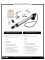
―WARNING―
Read all instructions before beginning installation
or use of this gate opener.
This operator excerts a high level of force.
Excercise caution at all times and stay clear of the
system during operation.
ESTATESWING.COM
E-S 500 / 502 Classic Series
INSTRUCTION MANUAL
Estate Swing Summary of Functions
The Estate Swing is only to be used for vehicular swing gates in a Class I setting.
Class I:
A vehicular gate opener (or system) intended for use in a home of one-to-four
single family dwelling, or a garage or parking area associated therewith.
The Estate Swing automated system was designed and built for controlling
vehicle access. Do not use for any other purpose.
The external automation with an electro-mechanical non-reversing linear arm
automates residential swing-leaf gates with leaves of up to 16’ in length. It
consists of an irreversible electro-mechanical operator with built in opening
and closing limits and utilizes a worm screw system. The irreversible system
ensures the gate is mechanical locked when the motor is not operating. A
lock still needs to be installed if security or high winds are a concern. A manual
release makes it possible to move the gate in the event of a power-cut or
fault.
For Your Assistance
Keep this manual safely stored after installation
Serial Number ________________________________
Date of Purchase _____________________________
Place of Purchase ____________________________
Have this information on hand while handling all service
and warranty issues.
E-S 500 / 502 Classic Series Instruction Manual
Table of Contents
The table of contents are listed to assist you locating a desired section. We do
however strongly suggest studying every page of the instruction manual before
attempting installation.
Section 1: Review of Specifications, Warnings, and Tools
Specifications of the Estate Swing and Components
Parts List
System Overview & Preliminary Checks
Tools Needed for Installation
1.1
1.2
1.3
1.4
Section 2: Installation
Manual Operation, Restoring Automation
IMPORTANT: Determining Setback—Pull to Open
Installation of Operator—Pull to Open
IMPORTANT: Determining Setback—Push to Open
Installation of Operator—Push to Open
2.1
2.2
2.4-.5
2.6
2.7-.8
Section 3: Wiring, Jumpers and Receiver
Removing Terminal Strips for Wiring
Wiring of Operator Arm(s) (Pull & Push to Open)
Installing Receiver and Setting Transmitters
Temporary Safety Jumpers & Dip Switch Settings
Power
3.1
3.2
3.3
3.4
3.5
Section 4: Programming the Operator
Adjust limit switches and determine run time
Operating Parameters Settings
4.1-.2
4.3
Section 5: Troubleshooting & Accessories
Troubleshooting
Control Board Overview
Accessories
E-S 500 / 502 Classic Series Instruction Manual
5.1-.3
5.4-.7
5.8
Specifications
MODEL
Power Supply
Backup Battery Voltage
Current (A)
Travel (in.)
Cycles per hour
Operating Ambient Temp
Protection class
Gate leaf max length (ft.)
Gate leaf max weight (lbs.)
Operator Type
Operator Weight
Gate Weight/ Length Ratio
100 lbs
250 lbs
400 lbs
650 lbs
800 lbs
1000 lbs
Estate Swing E-S500/502
24V AC, 50VA to 120VA
24V DC
3
13
50% Duty Cycle / Aprox. 35
-20 to 130 F
IP44
Up to 16
Up to 1000
Screw Drive
18 lbs
6'
X
X
X
X
X
X
8'
X
X
X
X
X
10'
X
X
X
X
12'
X
X
X
14'
X
X
16'
X
X
The above chart represents the maximum weight and length combinations that
this gate opener can handle. The lengths and weights are either for a single gate
or for a single leaf of a dual gate.
E-S 500 / 502 Classic Series Instruction Manual
1.1
Estate Swing Parts List
Master or Single Operator
A. Control Box with Control Board and
Receiver
B. Operator Arm with 7’ of Wire
C. Key
Slave Operator (if applicable)
A. N/A
B. Operator Arm with 7’ of Wire
C. Key
D. N/A
D. Transmitter
E. N/A
E. Transformer
F. Gate Mounting Bracket
G. Post Mounting Brackets
H. Connector Pins and C Rings
I. Mounting Hardware
1 - 3/8”x1 3/8” Hex bolts, washer, nut
1 - 5/16”x 1 3/8” Hex bolt, washer, nut
2 - 3/8”x 2” Carriage bolt, washers, nut
1 - 1/4” x 2” Hex bolt, washers, nut
F. Gate Mounting Bracket
G. Post Mounting Brackets
H. Connector Pins and C Rings
I. Mounting Hardware
1 - 3/8”x1 3/8” Hex bolts, washer, nut
1 - 5/16”x 1 3/8” Hex bolt, washer, nut
2 - 3/8”x 2” Carriage bolt, washers, nut
1 - 1/4” x 2” Hex bolt, washers, nut
Not Shown: Additional Wire
E-S 500 / 502 Classic Series Instruction Manual
1.2
Standard System Overview and Safety Zones
The system display to the below is a recommended standard system. Other approved
accessories can be installed. Photo sensors and a flashing light indicating gate
movement is recommended for safety purposes.
1,2 Estate Swing Operator • 3 Photocells (not included) • 4 Control board • 5 N/A
6 Push button opening device (not included) • 7 Receiver extension (not included) • 8
24Vdc flashing lamp (not included) • 9 Positive stop (not included) • 10 AC transformer
Notes: 1) When laying electrical cables, use appropriate rigid and/or flexible tube
2) Do not run any wires in the same conduit as110 AC power that may be in the
area. This will cause danger of electrocution.
IMPORTANT: Preliminary Checks
To ensure safety and an efficiently operating automated system, make sure the
following conditions are observed.
• The gate and post must be suitable for being automated. Check that the structure
is sufficiently strong and rigid, and its dimensions and weights conform to those
indicated on page 1.
• Make sure the leaves move smoothly without any irregular friction during entire
travel.
• Make sure the hinges are in good condition. Ball bearing hinges are ideal for gates
weighing over 200 lbs. or over 10’ in length.
• Make sure the gate is plumb and level.
• The fence post must be secured in the ground with concrete. This will prevent
alteration of alignments and leveling during installation and during cycles.
E-S 500 / 502 Classic Series Instruction Manual
1.3
Tools Needed for Installation
• Power Drill
• Crescent Wrench
• Flat Head Screwdriver
• Hacksaw
• Phillips Head
• Screwdriver
• C-Ring Pliers
• Tape Measure
• Level
• Wire Strippers
• C-clamps
• 3/8”, 1/4”, 5/16” Drill Bits
Other items may be needed prior to commencing installation. BOLDED items are
necessary to all applications.
• Positive post, bracket or door stop. Although the Estate Swing 300 features built in
limit switches.
• 16, 14 or 12 gauge, 2 conductor stranded direct burial low voltage wire will be
required to run power to your operator. Length and gauge are determined by
distance between transformer power supply and the control box.
• 4 - 3/8” Carriage Bolts will be needed to connect the 2 “L” shaped brackets to the
post. Length will be determined by the size of your posts.
• A metal support bracket may be needed to achieve the appropriate desired
setback. The metal support bracket will be bolted or welded to your post to give a
larger amount of space to mount the provided mounting bracket.
• A voltage meter and digital camera may be necessary to run diagnostic checks.
• If your transformer is going to be plugged into an outdoor outlet you will need to
weatherproof that outlet and transformer. Electrical boxes or plug covers can be
obtained from a local hardware store to accommodate both the plug and
transformer.
• Hardware to attach the control box to a post or fence.
• Watertight connectors for running wires into the control box.
E-S 500 / 502 Classic Series Instruction Manual
1.4
Manual Operation
1) Lift lock cover cap off.
2) Insert and turn provided key.
3) The operator can now be pull or
push open.
4) Replace lock cover to protect
lock from water and debris.
To exit manual mode, repeat the
above steps.
Restoring Automation
To maintain the proper performance of your
emergency release - please perform the
following service for your motor once per
year.
1. Remove the emergency release cap
2. Spray some WD-40 or other spray lubricant
into the release lock.
3. Allow the lubricant to soak in.
4. Apply a liberal dab of petroleum based
jelly or wheel bearing grease to coat the
release lock.
5. Put the cap securely back in place.
E-S 500 / 502 Classic Series Instruction Manual
2.1
IMPORTANT: Determining Correct Setback
PULL TO OPEN - Standard operation. This means the gate operator is mounted on the
inside of the property and pulls your gate in towards the property. If you are going to use
push to open operation “X” out the next 3 pages and use the push to open section
instructions.
To the right are 3 common
examples of setback mountings.
These are not the only options for
mounting.
There a 3 factors to keep in mind when
finding the setback mounting:
1) The measurements must be correct
from the center of the hinge of the gate
to the center of the hole on the mounting
bracket.
2) There must be clearance for your
opener to attach to your gate in the
closed position.
3) The brackets do not move or pivot
after mounting, if you can achieve the
setback and clearance then bracket
position is inconsequential.
It is best to C-Clamp brackets on and test
arm movement clearance before
permanently attaching them.
Variations to the ideal setback can be
made, so long as the total is less than the
combined measurements for the desired
opening arc and the motor body is more
than 2 inches away from the gate in both
the open and closed position. (setback
variations significantly reduces the length
and weight capacity of the operator)
A
B
Sum
a
6"
7 ½"
9 ½"
8 ½"
9"
9 ½"
14
16 ½
19
110°
100°
90°
To determine the position of the gate
mounting bracket (above is for the post
mounting bracket) refer to step 6 in the
section “Installation of operator”
E-S 500 / 502 Classic Series Instruction Manual
2.2
Installation of Operator—Pull-to-Open
1. Find the proper set back for your operator (from
previous page). Do this by holding the bottom “L”
shaped bracket against the post. Marking its
horizontal positioning on the post using a vertical
line up from the middle of the bracket. Also mark
your angled bracket for positioning on the “L”
shaped bracket. The hole on the end of the
angled bracket should be in the setback position.
Trace the bracket on cardboard and
HINT: use the cardboard to make a template.
2. Cut off the excess length (if any) of the
angled bracket using a hacksaw.
3. Position the angled bracket between the
two “L” shaped brackets in the same
position as when the setback was found.
Clamp the 3 brackets together. Drill through
the angled bracket using the pre-drilled
holes in the “L” shaped brackets using a
3/8” drill bit. Drill through all three brackets
using a 5/16” drill bit in a position behind the
first
hole.
4. Insert a 3/8” x 1” bolt in the center hole
and a 5/16” bolt in the rear hole. Secure
them using the provided nuts and lock
washers.
BEFORE PERMANENTLY ATTACHING ANY BRACKETS, BE
SURE TO TEST ARM MOTION AND CLEARANCE.
E-S 500 / 502 Classic Series Instruction Manual
2.4
Installation of Operator—Pull-to-Open
5. Temporarily position the gate side mounting bracket. (horizontal
position does not matter, vertical position on the gate is the position
you are matching to the post bracket.) Position your assembled gate
mounting along the previously drawn vertical line and level the
angled piece with the horizontal piece of the gate mounting bracket
using a level. Mark your holes, drill and attach the brackets using 4)
3/8” carriage bolts.
Gate Side Bracket
6. WITH THE GATE IN THE CLOSED POSITION measure 53” from the
center hole of the “boomerang” shaped bracket to the center hole
of the gate bracket – this should be the position of the gate bracket
on the closed gate.
7. Attach the gate mounting bracket using carriage bolts, nuts, and
washers.
E-S 500 / 502 Classic Series Instruction Manual
2.5
IMPORTANT: Determining Correct Setback
PUSH TO OPEN - This operation is commonly used if you driveway slopes up after the
gate, preventing it from swinging in. This means the gate operator is mounted on the
inside of the property and pushes your gate out away from the property.
To the right are 2 common
examples of setback mountings.
These are not the only options for
mounting.
There a 3 factors to keep in mind when
finding the setback mounting:
1) The measurements must be correct
from the center of the hinge of the gate
to the center of the hole on the mounting
bracket.
2) There must be clearance for you
opener to attach to your gate in the
open position.
3) The brackets do not move or pivot
after mounting, if you can achieve the
setback and clearance then bracket
position is inconsequential.
It is best to C-Clamp brackets on and test
arm movement clearance before
permanently attaching them.
To determine the position of the gate
mounting bracket (above is for the post
mounting bracket) refer to step 6 in the
section “Installation of operator - PTO”
A
B
Sum
a
6"
7½"
9 ½"
8 ½"
9"
9 ½"
14
16 ½
19
110°
100°
90°
Variations to the ideal setback can be made, so long as the total is less than the combined
measurements for the desired opening arc and the motor body is more than 2 inches away from the
gate in both the open and closed position. (setback variations significantly reduces the length and
weight capacity of the operator)
E-S 500 / 502 Classic Series Instruction Manual
2.6
Installation of Operator—Push-to-Open
1. Find the proper set back for your operator (from
previous page). Do this by holding the bottom “L”
shaped bracket against the post. Marking its
horizontal positioning on the post using a vertical
line up from the middle of the bracket. Also mark
your angled bracket for positioning on the “L”
shaped bracket. The hole on the end of the
angled bracket should be in the setback position.
Trace the bracket on cardboard and
HINT: use the cardboard to make a template.
2. Cut off the excess length (if any) of the
angled bracket using a hacksaw.
3. Position the angled bracket between the
two “L” shaped brackets in the same position
as when the setback was found. Clamp the 3
brackets together. Drill through the angled
bracket using the pre-drilled holes in the “L”
shaped brackets using a 3/8” drill bit. Drill
through all three brackets using a 5/16” drill bit
in a position behind the first hole.
4. Insert a 3/8” x 1” bolt in the center hole
and a 5/16” bolt in the rear hole. Secure
them using the provided nuts and lock
washers.
BEFORE PERMANENTLY ATTACHING ANY BRACKETS, BE
SURE TO TEST ARM MOTION AND CLEARANCE.
E-S 500 / 502 Classic Series Instruction Manual
2.7
Installation of Operator—Push-to-Open
5. Temporarily position the gate side mounting bracket. (horizontal
position does not matter, vertical position on the gate is the position
you are matching to the post bracket.) Position your assembled gate
mounting along the previously drawn vertical line and level the
angled piece with the horizontal piece of the gate mounting bracket
using a level. Mark your holes, drill and attach the brackets using 4)
3/8” carriage bolts.
Gate Side Bracket
6. WITH THE GATE IN THE OPEN POSITION measure 53” from the center
hole of the “boomerang” shaped bracket to the center hole of the
gate bracket – this should be the position of the gate bracket on the
closed gate.
7. Attach the gate mounting bracket using carriage bolts, nuts, and
washers.
E-S 500 / 502 Classic Series Instruction Manual
2.8
Troubleshooting
The gate opener is not stopping on the limit switches:
• Remove all pre-installed jumpers from the limit switch terminals that have limits
going to them. The slave gate terminals come pre-jumped for single operation, if
you are using a dual system pay particular attention to this detail and remove the
jumpers when you put your limit switches in.
• The limits are wired incorrectly—be sure that you are following the correct wiring
diagram for pull to open or push to open.
• Check setback— if setback is incorrect it will limit how far the gate will move per
inch of stroke length.
One or both arms are not moving:
• Check to be sure wiring color pattern matches the installation (Example: push to
open wiring for a push to open installation) - If the limits or motor are wiring
opposite the installation the board will believe it is closed or open when it is
actually the opposite and the arms will never move.
• Check the limit wires are correctly in the terminal blocks. The terminal blocks
come with the terminal clamps closed - however when the terminal clamps are
closed there is a small space below them one could mistake as place to insert a
wire. If this is done then conductivity of the connection will never be reached.
• Push or pull on the gate - if it moves the gears are disengaged and the gate is
in manual release mode.
General fix for user to understand operation.
Unlock the gate opener arm and move it to the half way position. Change the run
time to a low number (example: 2). Run the operator repeatedly.
The operator should run one direction for a 2 count and then the other for a 2
count. After you feel you have it following the run time correctly and swinging
level and easily, then start incrementally lengthening the run time.
Eventually the run time will allow the operator arm to reach both limit switches
and your setup is complete.
Single gate - Arm retracts and extends in a jerky manner:
The jumpers are not in place on LIMIT 2—all three need to be jumped together.
Dual gate - Only one arm moves:
• If one arm reaches a limit before the other arm moves, that other arm will never
move. In other words, second arm must move before first hits limit.
• If the device you are using to activate the gate is wired into PUSH 2 that only
opens leaf 1.
• Check your dual settings - if the dip switch is changed to dual with the power on
the setting will not take effect, turn the power off and then back on to have the
dual dip switch take effect. NOTE: If one leaf of a dual gate ever reaches its end
limit before the other leaf starts moving, the leaf that hasn’t started moving will not
begin: correct this by cycling the gates again and let it travel the full stroke or
decrease the delay between leafs. The options are 0-9 seconds delay.
E-S 500 / 502 Classic Series Instruction Manual
5.2
Wiring the Operator Arm(s)
For a dual gate use the provided wire to connect the secondary
motor to the control board.
Feed the wires through the white wire caps at the bottom of the
board. If gaps exist in the rubber wire cap after feeding the wires
through, seal with silicone.
Pull to Open
(Opening in towards
property)
!
It is important to choose the
correct operation type
Push to Open
(Opening out towards
the street)
E-S 500 / 502 Classic Series Instruction Manual
3.2
Installing and Setting Transmitters and Receivers
Plug the receiver into the control board with the dip
Receiver: switches of the receiver facing the inside of the
control board.
There is no programming, simply match the 9 dip
Dip
switch positions of the receiver to the 9 dip switch
Switches: positions in the remote located under the battery lid.
!
Tip: If interferance is occuring, change dip switches to
another random position on both remote and reciever.
E-S 500 / 502 Classic Series Instruction Manual
3.3
Temporary Safety Jumpers & Dip Switch Settings
If you are not using a safety
device like a photo eye or safety
loop the Photocell terminal must
remain jumped to the GND
terminal.
If you are using a SINGLE gate
installation the LIMIT 2 terminals
must remain jumped together.
For a DUAL gate jumpers must be
removed from limit terminals and
limit switch wires inserted.
Dip Switches—To change either dip switch you must turn the
power off before changing the setting.
!
1.
ON: Auto-close on (the gate will re-close
from the open position after a time set in
the programming section)
OFF: Auto-Close off
2.
ON: Dual gate opener (2 motors)
OFF: Single gate opener (1 motor)
IMPORTANT: We recommend before turning the gate
opener on for the first time to have dip switch 1 OFF. If
the dip switch is set to on, the gate will autoreclose
after turning it on without any intentional activation on
your part.
E-S 500 / 502 Classic Series Instruction Manual
3.4
Power
The Estate Swing E-S 500 comes with 1) 24V transformer. The transformer supplied
has 2 screw terminals to connect to. You may locate the transformer up to 200’
away from the control board using 16 gauge, 2 conductor stranded direct burial
low voltage wire. Do not use solid core wire.
Insert the two wires from the transformer into the two TRAN terminals on the
control board. The wires are not polarized, there is no positive or negative. DO
NOT SPLICE THE POWER CABLE WIRE.
!
Never run 110VAC power directly to the Estate Swing.
This will destroy the Estate Swing control board.
Never connect the power wire with the transformer plugged in. Contact
between the two lead wires, even for a second, will destroy the transformer.
Transformers are only warranted if the internal fuse is not blown. If the fuse is
blown an outside factor (shorting, surge, water, etc) has caused the transformer
not to function.
Plug the transformer into a 110 V AC outlet.
The transformer is not weather proof and must be kept in a covered area. Plug
covers are available from your dealer, contact 1-800-640-GATE for a dealer in
your area.
Two 12V DC batteries (Max 5 a/h per battery) may be run in series as backup to
the 24V transformer power. Running two 12V batteries in series creates a 24V
system, you cannot run them in parallel (see diagram above)
When you install new batteries - manually open the gate and allow the batteries
to charge for 12 hours through the system before using the gate opener.
E-S 500 / 502 Classic Series Instruction Manual
3.5
Find Limit Positions
Example of washer and magnet in closed
position (open for push-to-open)
1. Manually release the gate and move the gate to the desired closed
position.
2. Take a metal washer and drag it along the side of the grey shaft until it is
attracted by the internal magnet.
3. Move the limit switch on the bottom to line up with the washer.
Underneath the arm there are slides secured with Philip head screws. After
loosening the screws the switches will be able to slide. (picture of limits on
next page)
4. Move the gate to the open
position and repeat with the open
limit switch (as you open the gate
you can leave the washer on the
side and it will move along with the
magnet).
Example of washer and magnet in open position
(closed for push-to-open)
E-S 500 / 502 Classic Series Instruction Manual
4.1
Determine Run Time
Once you set up your remote, press the button and actuate your
gate a few times. When the gate stops on the limits: If the gate
has stopped short of or further than desired position, adjust the
limit switches:
After you have your limits in the correct position secure the
position of the switches with the screws and run your gate through
a few cycles. On the display you will see a count while the arms
are moving. This is your run time. Record your run time below.
ACTUAL RUN TIME: _____________________________
E-S 500 / 502 Classic Series Instruction Manual
4.2
Operating Parameters Set Up
PUSH 1 or PUSH 2 to increase or decrease the parameter. Then press SET button to move
to the next parameter.
1. Press SET button to begin.
2. LED shows P1: P1 is for setting your run time. The run time will be determined from the
time you had determined during the set up of the limit switches. Take that determined
run time and add 1 second. So if it takes 10 seconds to get from closed to open
between limit switches; set the run time to 11 seconds. The options are 0-99 seconds.
3. LED shows P2: P2 is for setting your slow down time. The gate opener will slow down to
half speed after the time set on P2 expires. If you wish to have the gate open and close
faster make the slow down start time a longer period of time. If you want to put less stress
on the gears and gate set the slow time shorter to slow the momentum sooner. The
options will adjust to match the previously set run time. NOTE: motor must be in slow
down to detect limits—be sure this number does not exceed the time the motor take to
move from one limit to the other.
4. LED shows P3: P3 is the force setting, the lower the number the easier the gate will
reverse directions when it meets resistance. This number may have to be changed to a
higher setting if your gate is obstructing unexpectedly. The number should be set to the
highest number during initial setup and reduced to the point of reliable operation that
takes into account change in gate resistance through out the year. The options are
0-32.
5. LED shows P4: P4 is for setting a delay between leafs if you have overlapping gates or
a gate lock. The motor wired into the master terminals (1) opens first if there is a delay
and closes second. It is recommended to have a delay of 3 seconds to avoid any
coming issues between leaves.
6. LED shows P5: P5 is the delay for automatic re-close from the open position – this
option needs to be turned on using the dip switch on the board. The options are 0-99
seconds.
7. LED shows P6: P6 is the release for the gate lock – this option determines the length of
time 24VDC will be sent out of terminals E_LOCK. The options are 1-4 seconds.
8. Press SET to finish. You should hear 3 beeps; this indicates parameter programming is
finished.
E-S 500 / 502 Classic Series Instruction Manual
4.3
Troubleshooting
If the gate opener will not move: (also see “one or both arms are not moving” on next page)
• Check wiring connections.
• Check to be sure safety jumpers are in place .
• If not using slave limit switches, be sure jumpers are in place.
• Be sure the arms are locked and not in manual operation.
• Check the fuse near the power supply—the proper way to inspect a fuse
is to remove it from its clips and check for continuity.
If the gate opener move a few inches or feet and stops or reverses
directions:
• Increase the force setting.
• Check the setback. The setback of the operator is important to correct
operation due to leverage the arm will have on the gate.
The gate does not reach the desired stop points:
• Adjust the limit switches.
• Lengthen the run time parameter.
• Check setback— if setback is incorrect it will limit how far the gate will
move per inch of stroke length.
If the gate will open but will not close:
• If you are not using safety devices the safety jumpers are in place.
• If you are using a safety device:
•Check to make sure you are using the normally closed connection
instead of the normally open.
•Check to be sure there is continuity being provided between the
common and normally closed wire of the safety device. If there is not
continuity then refer to the installation guide of the device to set up
properly.
The display of the board will not light up:
• Check the power supply for 24VAC.
• Check the fuse near the power supply—the proper way to inspect a fuse
is to remove it from its clips and check for continuity.
• The arms are not wired in or properly wired on the limit switch connections.
With out the limit switch connections being closed the board will not light up.
If limit motor is opening or closing past the limits
• Motor must be in slow down mode to detect limits. Check P2 parameter.
The slow down occurs AFTER the number that parameter is set to expires.
Example: If P2 is set to 14 and it takes 13 seconds to move from closed to
open it will not enter slow down mode. Decrease this number.
More on next page
E-S 500 / 502 Classic Series Instruction Manual
5.1
Troubleshooting
The gate opener is not stopping on the limit switches:
• Remove all pre-installed jumpers from the limit switch terminals that have
limits going to them. The slave gate terminals come pre-jumped for single
operation, if you are using a dual system pay particular attention to this
detail and remove the jumpers when you put your limit switches in.
• The limits are wired incorrectly—be sure that you are following the correct
wiring diagram for pull to open or push to open.
• Check setback— if setback is incorrect it will limit how far the gate will
move per inch of stroke length.
One or both arms are not moving:
• Check to be sure wiring color pattern matches the installation (Example:
push to open wiring for a push to open installation) - If the limits or motor are
wiring opposite the installation the board will believe it is closed or open
when it is actually the opposite and the arms will never move.
• Check the limit wires are correctly in the terminal blocks. The terminal
blocks come with the terminal clamps closed - however when the terminal
clamps are closed there is a small space below them one could mistake as
place to insert a wire. If this is done then conductivity of the connection will
never be reached.
• Push or pull on the gate - if it moves the gears are disengaged and the
gate is in manual release mode.
General fix for user to understand operation.
Unlock the gate opener arm and move it to the half way position. Change
the run time to a low number (example: 2). Run the operator repeatedly.
The operator should run one direction for a 2 count and then the other for a
2 count. After you feel you have it following the run time correctly and
swinging level and easily, then start incrementally lengthening the run time.
Eventually the run time will allow the operator arm to reach both limit
switches and your setup is complete.
Single gate - Arm retracts and extends in a jerky manner:
The jumpers are not in place on LIMIT 2—all three need to be jumped
together.
Dual gate - Only one arm moves:
• If one arm reaches a limit before the other arm moves, that other arm will
never move. In other words, second arm must move before first hits limit.
• If the device you are using to activate the gate is wired into PUSH 2 that
only opens leaf 1.
• Check your dual settings - if the dip switch is changed to dual with the
power on the setting will not take effect, turn the power off and then back
on to have the dual dip switch take effect.
E-S 500 / 502 Classic Series Instruction Manual
5.2
Troubleshooting
!
IF YOU CALL IN FOR TECHNICAL SUPPORT OR
WARRANTY SUPPORT: Before any control
board or motor will be permitted to be sent in
for testing or warranty you will be required to
e-mail digital photos to the technician.
This is done in your best interest to save unnecessary shipping expenses
and time lost. Many times we can come up with solutions to issues by
seeing pictures that relay information that is impossible to relay
through a phone conversation.
Below are examples of control board pictures and motor pictures that
we will be looking for:
Pictures shown are
actual customer photos
E-S 500 / 502 Classic Series Instruction Manual
5.3
Control Board Overview
!
CAUTION! Do not run 110V AC power direct to the
board. This will cause permanent damage to both
boards and void your warranty. Caution!
Gate Opener reactions to signals:
PUSH1 and Receiver (PUSH 1 terminal, PUSH 1 button, 5 Prong Receiver):
Details:
• Will activate gate with momentary contact (momentary contact between PUSH1
and V+) or if you momentarily press the PUSH1 button.
• Controls both leaves in 2 leaf mode (Dip switch 2 in the ON position).
• Acts as party mode control to suspend auto-reclose by activating while counting
down autoreclose in the open position.
Operational Sequence for terminal with autoclose ON (Dip switch 1 in on position):
1. In closed position - momentary contact will open gates.
2. When opening - momentary contact will stop gates and then it will auto reclose.
3. When stopped mid cycle waiting auto reclose - momentary contact will move the
gate in the direction opposite what it was moving before stopped.
4. When open and counting auto-reclose pause time - momentary contact will stop
pause time.
5. Stopped in open position from override of auto-reclose from PUSH1 or Receiver momentary contact will reactivate pause time and close gate.
6. When closing - momentary contact will stop the gate and then it will auto reclose.
Operational Sequence for terminal with autoclose OFF (Dip switch 1 in off position):
1. In closed position - momentary contact will open gates.
2. When opening - momentary contact will stop gates.
3. When stopped mid cycle - momentary contact will move the gate in the direction
opposite what it was moving before stopped.
4. When open - momentary contact will close gates.
5. When closing - momentary contact will stop the gate.
6. When stopped mid cycle - momentary contact will open the gate.
7. When open with auto-reclose off - momentary contact will have no effect.
8. When closing - momentary contact will re-open the gate.
E-S 500 / 502 Classic Series Instruction Manual
5.4
Control Board Overview
!
CAUTION! Do not run 110V AC power direct to the
board. This will cause permanent damage to both
boards and void your warranty. Caution!
Gate Opener reactions to signals:
PUSH2 (PUSH 2 terminal and PUSH 2 button):
Details:
• Will activate gate with momentary contact (momentary contact between PUSH2
and V+).
• Controls both leaves in 2 leaf mode (Dip switch 2 in the ON position)..
• Only opens the gate, never closes it.
• Pause time is able to be re-set indefinitely if this terminal is continuously closed
through a non-momentary contact (a connection between PUSH2 and V+ that is
not released) Then the time will be reset and held until the connection between
PUSH2 and V+ is released - then it will count down the pause time and reclose.
• Ideal for exit wand or exit loop.
Operational Sequence for terminal with autoclose ON (Dip switch 1 in on
position):
1. In closed position - momentary contact will open gates.
2. When opening - momentary contact will have no effect.
3. When stopped mid cycle from PUSH 1 or the Receiver - momentary
contact will open the gate.
4. When open with auto-reclose on - momentary contact will re-set pause
time and will start counting again after release of momentary contact. Closed
contact will continually re-set pause time and start counting down to reclose again
after contact is released.
5. When pause time countdown is stopped in open from a momentary contact of
PUSH 1 or the Receiver - momentary contact will have no effect.
6. When closing - momentary contact will re-open the gate.
Operational Sequence for terminal with autoclose OFF (Dip switch 1 in off
position):
1. In closed position - momentary contact will open gates.
2. When opening - momentary contact will have no effect.
3. When stopped mid cycle - momentary contact will open the gate.
4. When open with auto-reclose off - momentary contact will have no effect.
5. When closing - momentary contact will re-open the gate.
PUSH 1 and PUSH 2 – these terminals can hold as many normally open connections as
needed, they will be wired in parallel. They are used for keypads, push buttons, universal
receivers, etc.
E-S 500 / 502 Classic Series Instruction Manual
5.5
Control Board Overview
!
CAUTION! Do not run 110V AC power direct to the
board. This will cause permanent damage to both
boards and void your warranty. Caution!
Lamp
Terminal:
Sends pulses of 24VDC during opening and closing –
to be used with a 24VDC lamp.
E_Lock:
Sends a pulse (length of time determined by P6
parameter) of 24VDC for a solenoid gate lock during
opening.
A second 1 second pulse of power will be sent after
the closed limit switch is reach to assist in relocking
the gate lock.
Magnetic gate lock must be powered separately
and this terminal can be used to activate a relay that
cuts power to the magnetic lock at the beginning of
a cycle.
Provides 12V to be used with a photocell for gate
V+/
safety. The photocell terminal is a Normally Closed
Photocell/
connection – it must be jumped to GND when not
GND:
being used.
The power output on this terminal is very minimal, do
not exceed one accessory or 300 milliamps.
Do not attach accessories until after you have the gate
opener limit switches and parameters set up and the gate
opener functioning properly by remote.
E-S 500 / 502 Classic Series Instruction Manual
5.6
Control Board Overview
!
Display
Indicators:
CAUTION! Do not run 110V AC power direct to the
board. This will cause permanent damage to both
boards and void your warranty. Caution!
Lower right hand “dots” flashing normal pace:
Awaiting command / normal operation
Lower right hand “dots” flashing rapidly:
Safety terminal triggered / lacks connection
EL: Sending voltage to EL terminals (electric lock)
OP: Opening cycle
AU: Auto-reclose countdown
CL: Closing cycle
If the gate(s) come in contact with an obstruction
the gate(s) will reverse direction for 2 seconds
and stop to allow the obstacle to be cleared from
the gate path.
Buzzer/
If the gate(s) obstructs 3 times in a row the gate(s)
Obstructions: will go into a hard shutdown mode and a buzzer
alarm will sound. At this point no accessories or
remotes will be able to activate the gate opener
until the gate opener is reset by disconnecting
primary power (transformer) and secondary
power (back up batteries - if applicable).
E-S 500 / 502 Classic Series Instruction Manual
5.7
Installing Accessories
Accessory manuals for most make and model accessories
can be found on the web at:
www.EstateSwing.com/accessories
The accessory manuals you have or find at the above address may be
written to coincide with that manufacturers model of gate opener. To
determine correct terminals on your Estate Swing operator, use the
accessory terminal section of your Estate Swing manual. The following are
some common terms and abbreviations found in manuals:
Normally Open – abbr. N/O – Indicates a circuit that is left open during
normal operation of the gate operator. When a device closes this circuit it
signals the operator to perform a function. This circuit is the main circuit for
entry devices. (i.e. keypads, exit wands, push buttons, etc.)
Normally Closed – abbr. N/C – Indicates that in order for the gate opener
to be active this circuit must be closed. When a device opens this circuit it
stops the motion of the gate operator. This circuit is the main circuit for
safety devices. (i.e. photo eyes, safety loops, etc.)
Common – abbr. COM – This is the matching terminal for both Normally
Open and Normally Closed circuits to be connected to. Accessory wiring
that begins in a N/O or N/O terminal must have a wire that ends in a
Common terminal.
Ground – abbr. GND or GRD – Ground is sometimes also known as
negative. Common terminals are the same as Ground terminals. Ground
can also be the negative spade of the battery if it is being used in
association with positive voltage.
If a device has both a N/O and a N/C wire, both are never used at the
same time. Some devices can be used as either an opening device or a
safety device (i.e. gate crafters exit wand, NIR photo eye, etc.) If being
used as an opening device use the N/O and if being used as a safety
device use the N/C terminals.
E-S 500 / 502 Classic Series Instruction Manual
5.8